Device for bone fixation
Frigg , et al. March 2, 2
U.S. patent number 10,932,830 [Application Number 16/072,664] was granted by the patent office on 2021-03-02 for device for bone fixation. This patent grant is currently assigned to 41medical AG. The grantee listed for this patent is 41 medical AG. Invention is credited to Patrick Burki, Daniel Fluri, Robert Frigg.


| United States Patent | 10,932,830 |
| Frigg , et al. | March 2, 2021 |
Device for bone fixation
Abstract
A device for bone fixation comprising: a bone plate (1) which has a plate hole (2) suitable for receiving a bone screw (20), the plate hole (2) having an inner wall (4) made of a material which has a hardness H.sub.p; and a hollow cylinder- or hollow cone-shaped insert which is mounted in the plate hole (2), at least partially abuts the inner wall (4) and is suitable for accommodating the head (21) of a bone screw (20), the insert (10) being arranged in the plate hole (2) such that it is secured against rotation and consisting of a material that has a hardness H.sub.E<H.sub.p.
| Inventors: | Frigg; Robert (Bettlach, CH), Burki; Patrick (Bern, CH), Fluri; Daniel (Bettlach, CH) | ||||||||||
|---|---|---|---|---|---|---|---|---|---|---|---|
| Applicant: |
|
||||||||||
| Assignee: | 41medical AG (Bettlach,
CH) |
||||||||||
| Family ID: | 1000005391740 | ||||||||||
| Appl. No.: | 16/072,664 | ||||||||||
| Filed: | February 19, 2016 | ||||||||||
| PCT Filed: | February 19, 2016 | ||||||||||
| PCT No.: | PCT/CH2016/000032 | ||||||||||
| 371(c)(1),(2),(4) Date: | July 25, 2018 | ||||||||||
| PCT Pub. No.: | WO2017/139903 | ||||||||||
| PCT Pub. Date: | August 24, 2017 |
Prior Publication Data
| Document Identifier | Publication Date | |
|---|---|---|
| US 20190029741 A1 | Jan 31, 2019 | |
| Current U.S. Class: | 1/1 |
| Current CPC Class: | A61B 17/8047 (20130101); A61B 17/866 (20130101); A61B 17/8605 (20130101) |
| Current International Class: | A61B 17/80 (20060101); A61B 17/84 (20060101); A61B 17/86 (20060101) |
| Field of Search: | ;606/70-71,280-321 |
References Cited [Referenced By]
U.S. Patent Documents
| 6206881 | March 2001 | Frigg |
| 8784458 | July 2014 | White et al. |
| 2004/0254579 | December 2004 | Buhren |
| 2006/0058797 | March 2006 | Mathieu |
| 2006/0122602 | June 2006 | Konieczynski |
| 2007/0265629 | November 2007 | Martin et al. |
| 2008/0234677 | September 2008 | Dahners |
| 2010/0305569 | December 2010 | Leuenberger |
| 2011/0224737 | September 2011 | Lewis |
| 2013/0190829 | July 2013 | Batsch |
| 2014/0271029 | September 2014 | Arnett |
| 2015/0150610 | June 2015 | Impellizzeri |
| 2019/0269444 | September 2019 | Schneider |
| 2801330 | Nov 2014 | EP | |||
| 2004049962 | Jun 2004 | WO | |||
Attorney, Agent or Firm: Rankin, Hill & Clark LLP
Claims
The invention claimed is:
1. A device for bone fixation, comprising: a bone plate provided with a plate hole; and a hollow cylindrical or hollow conical insert supported in the plate hole, said insert abutting at least partially an inner wall of the plate hole and being configured to receive a head of a bone screw; wherein the entire bone plate, including the inner wall of the plate hole, consists of a material with a Vickers hardness H.sub.P, wherein the insert consists of a material with a Vickers hardness H.sub.E, wherein H.sub.E<H.sub.P, wherein the plate hole has an out of round shape, wherein the insert is positively locked in the plate hole by: (i) a cylindrically interrupted shape of the plate hole; or (ii) an elliptical shape of the plate hole; or (iii) a stop in the plate hole, such that the insert cannot shift inside the plate hole, cannot pivot inside the plate hole and cannot rotate inside the plate hole, and wherein the Vickers hardness H.sub.E of the material of the insert is in a range of 20% to 90% of the Vickers hardness H.sub.P of the material of the bone plate.
2. The device according to claim 1, wherein the Vickers hardness H.sub.E of the material of the insert is in the range of 120 to 200 HV.
3. The device according to claim 1, wherein the Vickers hardness of the material H.sub.P of the bone plate is in the range of 201 to 600 HV.
4. The device according to claim 1, wherein the bone plate and the insert each consist of a metal or a metal alloy.
5. The device according to claim 1, wherein the insert consists of pure titanium.
6. The device according to claim 1, wherein the plate hole has a central axis and wherein the insert is arranged concentrically to the central axis.
7. The device according to claim 1, wherein the insert has a through slot.
8. The device according to claim 1, wherein the insert has a cross section in a form of a circle with at least one non-circular portion.
9. The device according to claim 1, wherein the insert has a cross section in a form of a polygon.
10. The device according to claim 1, wherein an outside diameter of the insert is greater than an inside diameter of the plate hole.
11. The device according to claim 1, further comprising a bone screw which comprises a head with an outside thread.
12. The device according to claim 11, wherein the head of the bone screw tapers at least partially in a direction of a screw tip.
13. The device according to claim 11, wherein the head of the bone screw consists of a material with a hardness H.sub.S, and wherein H.sub.S>H.sub.E.
Description
The invention relates to a device for bone fixation.
The invention is based on the problem of creating a device for bone fixation which permits a secure connection between the construct bone screw/insert/bone plate and therefore guarantees a secure anchoring of the construct as a whole on the bone, wherein the risk of the rotating of the insert in the plate is minimized during the locking procedure and of the resulting tearing out of the previously formed thread in the bone.
The invention solves the problem posed by a device for bone fixation which has the features claimed herein.
The advantages achieved by the invention are substantially the fact that due to the special pairing of material during the introducing of a bone screw with a thread chat head into the plate hole provided with the insert, the knife-shaped flanks of the screw head thread displace the material of the insert--which is relatively soft in comparison to the bone plate material--so that a fixed compound is achieved between the screw head--the insert--and the bone plate.
Furthermore, a cold welding between the screw and the plate is prevented by the different materials, which is especially relevant during a revision of the plate.
Other advantageous embodiments of the invention can be commented on as follows:
In a special embodiment the bone plate consists of a material with the same hardness as the material of the inner wall of the plate hole.
In another embodiment the Vickers hardness of the material of the insert is in the range of 20 to 90% of the Vickers hardness of the material of the bone plate.
In another embodiment the Vickers hardness of the material of the insert is in the range of 120 to 200 HV.
In another embodiment the Vickers hardness of the material of the insert is in the range of 201 to 600 HV.
In another embodiment the bone plate and the insert consist of a metal or of a metal alloy.
In another embodiment the bone plate consists of a steel alloy.
In yet another embodiment the bone plate consists of pure titanium or of a titanium alloy.
In yet another embodiment the bone plate consists of a cobalt-chromium-molybdenum alloy.
In another embodiment the insert consists of pure titanium, preferably of titanium grade 2.
In another embodiment the plate hole is provided with means which allows the receiving of the insert in the plate bore in a manner security against rotation. This embodiment can be realized, e.g., by one or more projections from the inner wall of the plate hole and notches, slits corresponding to the projections or by the use of through bores. The rotation-proof receiving of the insert in the plate hole can also be realized by the projections on the outer wall of the insert and by notches in the inner wall of the plate hole which fit it.
In another embodiment the plate hole has an out of round or cylindrically interrupted shape. The plate hole preferably has the shape of a circle with at least one lacking circular segment or the shape of at least two partially overlapping circles.
In another embodiment the plate hole has an elliptical shape.
In another embodiment the plate hole has a central axis, wherein the insert is arranged concentrically to the central axis. The advantage of this embodiment is that a concentric hole-ring construct has an elevated angular stability. A ring which can incline in the hole can not be compressed as well, i.e., the pressing between ring and plate is lowered compared to a concentric construct.
In another embodiment the rotation-proof receiving of the insert in the plate hole is positively realized. This secures the insert against shifting, pivoting and rotating inside the plate hole.
In another embodiment the rotation-proof receiving the insert in the plate hole is realized by a stop in the plate hole.
In another embodiment the insert has a continuous slot. The slot makes possible the mounting of the insert in the plate hole by elastic deformation of the interrupted geometry.
In another embodiment the insert has a cross section in the shape of a circle with at least one lacking circular segment.
In another embodiment the insert has a cross section with substantially the shape of a polygon, preferably of a triangle. In an additional embodiment the corners of the polygon are rounded.
In another embodiment the insert is firmly connected to the bone plate.
In a special embodiment the bone plate (without insert) is constructed in one part.
In another embodiment the plate hole is constructed cylindrically.
In yet another embodiment the plate hole is conically constructed. This embodiment makes possible a self-locking of the insert and of the plate hole.
In another embodiment the semi-conical angle .alpha. of the plate hole is in the range of 40.degree.>.alpha.>0.degree., preferably in the range of 20.degree.>.alpha.>0.degree..
In another embodiment the insert is arranged in a self-locking manner in the plate hole.
In another embodiment the insert is secured against axial shifting in the plate hole. This can take place, for example, by everting material or by shouldering in the plate hole.
In another embodiment the insert has a shape which is at least partially congruent to the plate hole.
In another embodiment the outside diameter of the insert is greater than the inside diameter of the plate hole.
In another embodiment the insert is not held by a press-fit in the plate hole. This avoids that the two parts can disconnect.
In a special embodiment the device comprises a bone screw which comprises a head with an outside thread.
In another embodiment the outside thread of the screw head is multiply threaded.
In another embodiment the thread pitch of the head thread is in the range between 1 mm and 4 mm.
In another embodiment the outer thread of the screw head is a single thread.
In another embodiment the thread pitch of the head thread is in the range between 0.2 mm and 1 mm.
In another embodiment the outer thread of the screw head has a thread depth of at least 0.1 mm. The advantage of this embodiment is that the thread flanks of the outer thread can cut into the insert by cold deformation without chips with it. As a consequence, the insert-plate construct receives a better angular stability, i.e., it is capable of receiving a higher torque in the sense of angular stability.
In another embodiment the head of the bone screw tapers at least partially in the direction of the screw tip.
In another embodiment the bone screw head consists of a material whose hardness is greater than the hardness of the insert material. As a result, the locking of the screw head by the deformation of the softer insert by the harder material of the screw head is achieved.
In another embodiment the bone screw head consists of a steel alloy, e.g., implant steel 1.4441.
In another embodiment the bone screw head consists of titanium.
In another embodiment the Vickers hardness of the material of the bone screw (20) is in the range of 110 to 500% of the Vickers hardness of the insert material.
In another embodiment the Vickers hardness of the material of the bone screw and the Vickers hardness of the material of the bone plate are identical. The bone screw and the bone plate preferably consist of the same material.
In another embodiment the Vickers hardness of the material of the bone screw is in the range of 110 to 500% of the Vickers hardness of the material of the bone plate.
In another embodiment the Vickers hardness of the bone screw material is in the range of 201 to 600 HV.
The invention and further developments of the invention are explained in detail in the following using the partially schematic views of several exemplary embodiments.
In the drawings:
FIG. 1 shows a perspective view of an embodiment of the device according to the invention;
FIG. 2 shows a perspective view of another embodiment of the device according to the invention;
FIG. 3 shows a perspective view of an embodiment of the plate hole of the device according to the invention;
FIG. 4 shows a perspective view of another embodiment of the plate hole of the device according to the invention;
FIG. 5 shows a schematic view of another embodiment of the insert according to the invention for the device according to the invention;
FIG. 6 shows a perspective view of an embodiment of the insert according to the invention;
FIG. 7 shows a perspective view of another embodiment of the insert according to the invention;
FIG. 8 shows a top view of an embodiment of the bone screw for the device according to the invention;
FIG. 9 shows a longitudinal section through an embodiment of a device according to the invention;
FIG. 10 shows a longitudinal section through another embodiment of a device according to the invention;
FIG. 11 shows a longitudinal section of an insert of the device according to the invention;
FIG. 12 shows a top view of an insert of a device according to the invention;
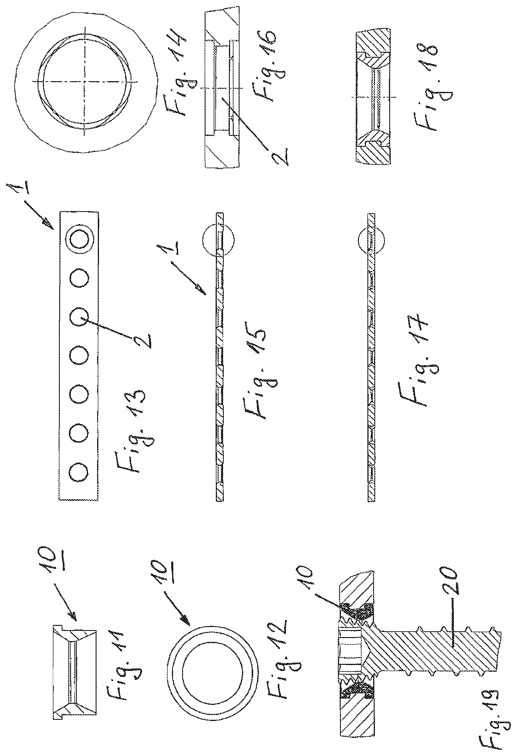
FIG. 13 shows a view of a bone plate of a device according to the invention from below;
FIG. 14 shows an enlarged view of FIG. 13;
FIG. 15 shows a longitudinal section of FIG. 13;
FIG. 16 shows an enlarged view of FIG. 15;
FIG. 17 shows a longitudinal section of the bone plate according to FIG. 15 with inserted insert;
FIG. 18 shows an enlarged view of FIG. 17;
FIG. 19 shows an enlarged longitudinal section of fa device according to the invention with an inserted screw and a deformed insert.
The embodiment shown in FIG. 1 of a device for bone fixation comprises a bone plate 1 with several plate holes 2 which each have a central axis 3 and an inner wall 4. The plate hole 2 is cylindrically constructed and is provided with an insert 10 which is suited for receiving a screw head. The outer wall of the insert 10 is congruent with the inner wall 4 of the cylindrical plate hole 2. The rotation-proof arrangement of the insert 10 in the plate hole 2 takes place by the positive locking after the deformation of the plate by the insert 10.
FIG. 1 shows a cylindrical insert 10 which is at first placed into the plate. The bone plate 1 is then deformed under force by a stamp so that the plate material flows over the insert 10. The securing against rotation and the axial security are given by the free positions of the insert 10.
The inserts 10 can also be conical.
The embodiment shown in FIG. 2 comprises a bone plate 1 with several plate holes 2 which each have a central axis 3 and an inner wall 4. The plate hole 2 has an out of round or cylindrically interrupted shape and is provided with a projection 5 extending out of the inner wall 4 in the direction of the central axis 3. The plate hole 2 comprises an insert 10 suitable for receiving a screw head. The insert 10 comprises a slot 11 which fits the projection 5 (the 11 is not sketched in FIG. 2) so that the insert 10 is arranged in the plate hole 2 in a manner security against rotation.
FIG. 3 shows a perspective view onto a part of a bone plate 1 with a plate hole 2 with a central axis 3 and an inner wall 4 without the inserted insert 10. The plate hole 2 is cylindrical.
FIG. 4 shows a perspective view of a part of the bone plate 1 with a plate hole 2 with a central axis 3 and an inner wall 4 without the inserted insert 10. The plate hole 2 has an out of round or cylindrically interrupted shape. The inner wall 4 of the plate hole 2 is provided with a projection 5 extending in the direction of the central axis 3.
FIG. 5 shows a schematic view of an insert 10 that has the shape of a polygon (triangle) with rounded corners.
FIG. 6 shows a perspective view of an insert 10 for a device for bone fixation. The insert 10 is provided with a continuous slot 11 with which the rotation-proof arrangement of the insert 10 in the plate hole 2 is achieved. The outer wall of the insert 10 has a radial groove 12 which makes possible a securing of the insert 10 in the plate hole 2 against axial shifting when the insert 10 is set into the plate hole 2 with corresponding everting material.
FIG. 7 shows a perspective view of another insert 10 for a device for bone fixation. The insert 10 is provided with two notches 13 which--during the insertion of the insert 10 into the plate hole 2 with corresponding shoulders--are produced after the deformation (for example, by pressing, welding or stamping). The deformation and the corresponding production of the two notches brings about a securing against rotation and also a securing against axial shifting of the insert 10 in the plate hole 2.
FIG. 8 is a top view of a bone screw 20 comprising a head 21 provided with an outer thread 22. The head 21 of the bone screw 20 tapers in the direction of the screw tip 23.
FIG. 9 shows a longitudinal section of a bone plate 1 with an inserted insert 10 and with a bone screw 20. The plate hole 2 has indentations in which the insert 10 is positioned so that the insert 10 is secured in the plate hole 2 against axial shifting. The locking of the screw head 21 in the plate hole 2 takes place by the deformation/shaping of the hard screw head thread into the softer material of the insert 10 (titanium) by the harder material (steel) of the outer thread 22 of the head 21 of the screw 20. The insert 10 is arranged in the plate hole 2 in a manner secured against rotation so that it cannot rotate during the deformation procedure.
FIG. 10 shows a longitudinal section of another bone plate 1 with an inserted insert 10 and a bone screw 20. The insert 10 has a radial groove 12 (not shown in FIG. 10) which secures the insert 10 in the plate hole 2 against axial shifting by the corresponding eversion 14 of the plate hole 2. Furthermore, the insert 10 has a continuous slot 11. FIG. 10 shows the longitudinal section of an embodiment in which the longitudinal section runs through the slot 11. The locking of the screw head 21 (not shown in FIG. 10) in plate hole 2 takes place by the deformation of the softer material of the insert 10 (titanium) by the harder material of the outer thread 22 (not shown in FIG. 10) of the head 21 of the screw 20 (steel). The plate hole 10 has an out of round or cylindrically interrupted shape so that the insert 10 cannot rotate in the plate hole 2 during the screwing in procedure. The softer material (titanium) of the insert 10 is pressed into the harder material (steel) of the bone plate 1 simultaneously with the deformation of the material of the insert 10 by the screw 20. The resulting positive and non-positive locking secures the insert 10 rotationally and axially.
FIG. 11 shows a cylindrical insert 10 in a sectional view with a 2-fold conical inner geometry and a narrow, cylindrical rib. FIG. 12 shows a top view of the insert 10 with a shoulder. FIG. 13 shows a bone plate 1 with the plate holes 2 in a view from underneath. FIG. 14 is an enlargement of the latter. FIG. 15 shows a longitudinal section of the same bone plate 1 and FIG. 16 shows the enlargement of FIG. 14. FIG. 16 shows a plate hole 2 with a cylindrical profile with 2 shoulders. In FIG. 16 this is lower at the top than at the bottom. In addition, the plate hole 2 has four free positions which are placed only on one side; they will serve later for the securing of the rotation.
Procedure:
The insert 10 is pressed or laid into the bone plate 1 from the side which has no free positions. Subsequently, the lower part of the insert 10 is deformed with a stamp into the shoulder with the free positions, for example, with the press. Therefore, the material flows into the free position and the shoulders. The positive locking, the securing against rotation and the axial securing are given. This can be recognized in FIG. 17 and FIG. 18. FIG. 19 shows a formed-in bone screw with the deformed insert 10 and with the bone plate 1.
The following material combinations are especially suitable for the present invention. Grades 2 and 4 designated pure titanium with different degrees of purity. Titanium grade 2 is an unalloyed titanium with an average hardness of 150 HV (Vickers hardness). Titanium grade 4 is an unalloyed titanium with an elevated oxygen content and with an average hardness of 250 HV (Vickers hardness).
TABLE-US-00001 Plate material Insert material Screw material Titanium grade 4 Titanium grade 2 Titanium grade 4 1.4441 implant steel Cobalt-chrome-molybdenum Titanium grade 2 Titanium grade 4 CCM 1.4441 implant steel 1.4441 implant steel Titanium grade 2 Titanium grade 4 1.4441 implant steel
* * * * *
D00000
D00001
D00002
D00003
XML
uspto.report is an independent third-party trademark research tool that is not affiliated, endorsed, or sponsored by the United States Patent and Trademark Office (USPTO) or any other governmental organization. The information provided by uspto.report is based on publicly available data at the time of writing and is intended for informational purposes only.
While we strive to provide accurate and up-to-date information, we do not guarantee the accuracy, completeness, reliability, or suitability of the information displayed on this site. The use of this site is at your own risk. Any reliance you place on such information is therefore strictly at your own risk.
All official trademark data, including owner information, should be verified by visiting the official USPTO website at www.uspto.gov. This site is not intended to replace professional legal advice and should not be used as a substitute for consulting with a legal professional who is knowledgeable about trademark law.