Tissue-removing catheter with rotatable cutter
Guggenheimer , et al. March 2, 2
U.S. patent number 10,932,811 [Application Number 15/816,744] was granted by the patent office on 2021-03-02 for tissue-removing catheter with rotatable cutter. The grantee listed for this patent is Covidien LP. Invention is credited to Benjamin Fruland, Ethan A. Guggenheimer, Thomas McPeak, Lucas Schneider.


View All Diagrams
| United States Patent | 10,932,811 |
| Guggenheimer , et al. | March 2, 2021 |
Tissue-removing catheter with rotatable cutter
Abstract
A tissue-removing catheter includes a cutting element. A radially innermost portion of the leading radial wall of a raised element of the cutting element may be spaced a radial distance from the longitudinal axis that is less than 66% of the radius of the annular cutting edge. The cutting element may be extendable through the window during operation such that as the cutting element is being rotated about its longitudinal axis, less than an entire radial portion of the leading radial wall passes through the window. A plurality of abrading members may be formed on at least the central portion of the inner surface of the cutting element to abrade hardened tissue as the cutting element is rotating about its longitudinal axis. A radially outermost portion of the leading radial edge of the raised element may be spaced apart radially from an inner surface of the cutting element.
| Inventors: | Guggenheimer; Ethan A. (Minnetonka, MN), Schneider; Lucas (Champlin, MN), McPeak; Thomas (Shakopee, MN), Fruland; Benjamin (Blaine, MN) | ||||||||||
|---|---|---|---|---|---|---|---|---|---|---|---|
| Applicant: |
|
||||||||||
| Family ID: | 1000005391722 | ||||||||||
| Appl. No.: | 15/816,744 | ||||||||||
| Filed: | November 17, 2017 |
Prior Publication Data
| Document Identifier | Publication Date | |
|---|---|---|
| US 20180070980 A1 | Mar 15, 2018 | |
Related U.S. Patent Documents
| Application Number | Filing Date | Patent Number | Issue Date | ||
|---|---|---|---|---|---|
| 13671695 | Nov 8, 2012 | 9943329 | |||
| Current U.S. Class: | 1/1 |
| Current CPC Class: | A61B 17/320758 (20130101); A61B 17/320783 (20130101); A61B 2017/320775 (20130101); A61B 2017/320791 (20130101); A61B 2017/320004 (20130101) |
| Current International Class: | A61B 17/3207 (20060101); A61B 17/32 (20060101) |
References Cited [Referenced By]
U.S. Patent Documents
| 1481078 | January 1924 | Albertson |
| 2178790 | November 1939 | Henry |
| 2701559 | February 1955 | Cooper |
| 2850007 | September 1958 | Lingley |
| 3064651 | November 1962 | Henderson |
| 3082805 | March 1963 | Royce |
| 3320957 | May 1967 | Sokolik |
| 3614953 | October 1971 | Moss |
| 3683891 | August 1972 | Eskridge et al. |
| 3705577 | December 1972 | Sierra |
| 3732858 | May 1973 | Banko |
| 3749085 | July 1973 | Wilson et al. |
| 3800783 | April 1974 | Jamshidi |
| 3815604 | June 1974 | O'Malley et al. |
| 3831585 | August 1974 | Brondy et al. |
| 3837345 | September 1974 | Matar |
| 3845375 | October 1974 | Stiebel |
| 3937222 | February 1976 | Banko |
| 3945375 | March 1976 | Banko |
| 3976077 | August 1976 | Kerfoot, Jr. |
| 3995619 | December 1976 | Glatzer |
| 4007732 | February 1977 | Kvavle et al. |
| 4020847 | May 1977 | Clark, III |
| 4030503 | June 1977 | Clark, III |
| 4034744 | July 1977 | Goldberg |
| 4038985 | August 1977 | Chiulli |
| 4112708 | September 1978 | Fukuda |
| 4177797 | December 1979 | Baylis et al. |
| 4210146 | July 1980 | Banko |
| 4273128 | June 1981 | Lary |
| 4306562 | December 1981 | Osborne |
| 4306570 | December 1981 | Matthews |
| 4349032 | September 1982 | Koyata |
| 4368730 | January 1983 | Sharrock |
| 4424045 | January 1984 | Kulischenko et al. |
| 4436091 | March 1984 | Blanko |
| 4445509 | May 1984 | Auth |
| 4490139 | December 1984 | Huizenga et al. |
| 4494057 | January 1985 | Hotta |
| 4512344 | April 1985 | Barber |
| 4589412 | May 1986 | Kensey |
| 4603694 | August 1986 | Wheeler |
| 4620547 | November 1986 | Boebel |
| 4631052 | December 1986 | Kensey |
| 4646719 | March 1987 | Neuman et al. |
| 4646736 | March 1987 | Auth |
| 4646738 | March 1987 | Trott |
| 4649919 | March 1987 | Thimsen et al. |
| 4653496 | March 1987 | Bundy et al. |
| 4664112 | May 1987 | Kensey et al. |
| 4669469 | June 1987 | Gifford, III et al. |
| 4686982 | August 1987 | Nash |
| 4692141 | September 1987 | Mahurkar |
| 4696298 | September 1987 | Higgins et al. |
| 4696667 | September 1987 | Masch |
| 4705038 | November 1987 | Sjostrom et al. |
| 4706671 | November 1987 | Weinrib |
| 4728319 | March 1988 | Masch |
| 4729763 | March 1988 | Henrie |
| 4730616 | March 1988 | Frisbie et al. |
| 4732154 | March 1988 | Shiber |
| 4733662 | March 1988 | DeSatnick et al. |
| 4747406 | May 1988 | Nash |
| 4747821 | May 1988 | Kensey et al. |
| 4749376 | June 1988 | Kensey et al. |
| 4754755 | July 1988 | Husted |
| 4757819 | July 1988 | Yokoi et al. |
| 4765332 | August 1988 | Fischell et al. |
| 4771774 | September 1988 | Simpson et al. |
| 4781186 | November 1988 | Simpson et al. |
| 4784636 | November 1988 | Rydell |
| 4790812 | December 1988 | Hawkins, Jr. et al. |
| 4794931 | January 1989 | Yock |
| 4817613 | April 1989 | Jaraczewski et al. |
| 4819634 | April 1989 | Shiber |
| 4819635 | April 1989 | Shapiro |
| 4838268 | June 1989 | Keith et al. |
| 4842579 | June 1989 | Shiber |
| 4844064 | July 1989 | Thimsen et al. |
| 4846192 | July 1989 | MacDonald |
| 4848343 | July 1989 | Vvallsten et al. |
| 4850957 | July 1989 | Summers |
| 4857046 | August 1989 | Stevens et al. |
| 4867157 | September 1989 | McGurk-Burleson et al. |
| 4870953 | October 1989 | DonMicheal et al. |
| 4883458 | November 1989 | Shiber |
| 4886061 | December 1989 | Fischell et al. |
| 4886490 | December 1989 | Shiber |
| 4887613 | December 1989 | Farr et al. |
| 4894051 | January 1990 | Shiber |
| 4899757 | February 1990 | Pope, Jr. et al. |
| 4919133 | April 1990 | Chiang |
| 4923462 | May 1990 | Stevens |
| 4926858 | May 1990 | Gifford, III et al. |
| 4928693 | May 1990 | Goodin et al. |
| 4936987 | June 1990 | Persinski et al. |
| RE33258 | July 1990 | Onik et al. |
| 4950238 | August 1990 | Sullivan |
| 4954338 | September 1990 | Mattox |
| 4957482 | September 1990 | Shiber |
| 4966604 | October 1990 | Reiss |
| 4973409 | November 1990 | Cook |
| 4979939 | December 1990 | Shiber |
| 4979951 | December 1990 | Simpson |
| 4986807 | January 1991 | Farr |
| 4990134 | February 1991 | Auth |
| 4994067 | February 1991 | Summers |
| 4997435 | March 1991 | Demeter |
| 5000185 | March 1991 | Yock |
| 5002553 | March 1991 | Shiber |
| 5003918 | April 1991 | Olson et al. |
| 5007896 | April 1991 | Shiber |
| 5007917 | April 1991 | Evans |
| 5009659 | April 1991 | Hamlin et al. |
| 5011490 | April 1991 | Fischell et al. |
| 5019088 | May 1991 | Farr |
| 5024234 | June 1991 | Leary et al. |
| 5024651 | June 1991 | Shiber |
| 5026384 | June 1991 | Farr et al. |
| 5029588 | July 1991 | Yock et al. |
| 5030201 | July 1991 | Palestrant |
| 5047040 | September 1991 | Simpson et al. |
| 5049124 | September 1991 | Bales, Jr. |
| 5053044 | October 1991 | Mueller et al. |
| 5054492 | October 1991 | Scribner et al. |
| 5061273 | October 1991 | Yock |
| 5064435 | November 1991 | Porter |
| 5071425 | December 1991 | Gifford, III et al. |
| 5074841 | December 1991 | Ademovic et al. |
| 5077506 | December 1991 | Krause |
| 5078722 | January 1992 | Stevens |
| 5078723 | January 1992 | Dance et al. |
| 5084010 | January 1992 | Plaia et al. |
| 5085662 | February 1992 | Willard |
| 5087265 | February 1992 | Summers |
| 5092839 | March 1992 | Kipperman |
| 5092873 | March 1992 | Simpson et al. |
| 5095911 | March 1992 | Pomeranz |
| 5100423 | March 1992 | Fearnot |
| 5100424 | March 1992 | Jang et al. |
| 5100426 | March 1992 | Nixon |
| 5101806 | April 1992 | Hunt et al. |
| 5108500 | April 1992 | Mattox |
| 5110822 | May 1992 | Sherba et al. |
| 5112345 | May 1992 | Farr |
| 5114399 | May 1992 | Kovalcheck |
| 5115814 | May 1992 | Griffith et al. |
| 5116352 | May 1992 | Schnepp-Pesch et al. |
| 5120323 | June 1992 | Shockey et al. |
| 5127902 | July 1992 | Fischell |
| 5127917 | July 1992 | Niederhauser et al. |
| 5135531 | August 1992 | Shiber |
| 5139506 | August 1992 | Bush |
| 5154705 | October 1992 | Fleischhacker et al. |
| 5154724 | October 1992 | Andrews |
| 5165421 | November 1992 | Fleischhacker et al. |
| 5176693 | January 1993 | Pannek, Jr. |
| 5178625 | January 1993 | Groshong |
| 5181920 | January 1993 | Mueller et al. |
| 5183432 | February 1993 | Noguchi |
| 5190528 | March 1993 | Fonger et al. |
| 5192291 | March 1993 | Pannek, Jr. |
| 5195956 | March 1993 | Stockmeier |
| 5211651 | May 1993 | Reger et al. |
| 5217474 | June 1993 | Zacca et al. |
| 5222966 | June 1993 | Perkins et al. |
| 5224488 | July 1993 | Neuffer |
| 5224945 | July 1993 | Pannek, Jr. |
| 5224949 | July 1993 | Gomringer et al. |
| 5226909 | July 1993 | Evans et al. |
| 5226910 | July 1993 | Kajiyama et al. |
| 5234451 | August 1993 | Osypka |
| 5242460 | September 1993 | Klein et al. |
| 5242461 | September 1993 | Kortenbach et al. |
| 5250059 | October 1993 | Andreas et al. |
| 5250065 | October 1993 | Clement et al. |
| 5261877 | November 1993 | Fine et al. |
| 5263928 | November 1993 | Trauthen et al. |
| 5263959 | November 1993 | Fischell |
| 5267955 | December 1993 | Hanson |
| 5267982 | December 1993 | Sylvanowicz |
| 5269793 | December 1993 | Simpson |
| 5273526 | December 1993 | Dance et al. |
| 5282484 | February 1994 | Reger |
| 5284486 | February 1994 | Kotula et al. |
| 5285795 | February 1994 | Ryan et al. |
| 5290303 | March 1994 | Pingleton et al. |
| 5295493 | March 1994 | Radisch, Jr. |
| 5306294 | April 1994 | Winston et al. |
| 5308354 | May 1994 | Zacca et al. |
| 5312427 | May 1994 | Shturman |
| 5314438 | May 1994 | Shturman |
| 5318032 | June 1994 | Lonsbury et al. |
| 5318528 | June 1994 | Heaven et al. |
| 5318576 | June 1994 | Plassche, Jr. et al. |
| 5321501 | June 1994 | Swanson et al. |
| 5322508 | June 1994 | Viera |
| 5336167 | August 1994 | Sullivan et al. |
| 5350390 | September 1994 | Sher |
| 5356418 | October 1994 | Shturman |
| 5358472 | October 1994 | Vance et al. |
| 5358485 | October 1994 | Vance et al. |
| 5360432 | November 1994 | Shturman |
| 5366463 | November 1994 | Ryan |
| 5368035 | November 1994 | Hamm et al. |
| 5370609 | December 1994 | Drasler et al. |
| 5370651 | December 1994 | Summers |
| 5372601 | December 1994 | Lary |
| 5372602 | December 1994 | Burke |
| 5373849 | December 1994 | Maroney et al. |
| 5377682 | January 1995 | Ueno et al. |
| 5378234 | January 1995 | Hammerslag et al. |
| 5383460 | January 1995 | Jang et al. |
| 5395311 | March 1995 | Andrews |
| 5395313 | March 1995 | Naves et al. |
| 5395335 | March 1995 | Jang |
| 5397345 | March 1995 | Lazarus |
| 5402790 | April 1995 | Jang et al. |
| 5409454 | April 1995 | Fischell et al. |
| 5413107 | May 1995 | Oakley et al. |
| 5419774 | May 1995 | Willard et al. |
| 5421338 | June 1995 | Crowley et al. |
| 5423799 | June 1995 | Shiu |
| 5423846 | June 1995 | Fischell |
| 5427107 | June 1995 | Milo et al. |
| 5429136 | July 1995 | Milo et al. |
| 5431673 | July 1995 | Summers et al. |
| 5441510 | August 1995 | Simpson et al. |
| 5443446 | August 1995 | Shturman |
| 5443497 | August 1995 | Venbrux |
| 5444078 | August 1995 | Yu et al. |
| 5445155 | August 1995 | Sieben |
| 5449369 | September 1995 | Imran |
| 5454809 | October 1995 | Janssen |
| 5456667 | October 1995 | Ham et al. |
| 5456689 | October 1995 | Kresch et al. |
| 5458585 | October 1995 | Salmon et al. |
| 5459570 | October 1995 | Swanson et al. |
| 5464016 | November 1995 | Nicholas et al. |
| 5466382 | November 1995 | Downey et al. |
| 5485840 | January 1996 | Bauman |
| 5487729 | January 1996 | Avellanet et al. |
| 5489295 | February 1996 | Piplani et al. |
| 5491524 | February 1996 | Hellmuth et al. |
| 5496267 | March 1996 | Drasler et al. |
| 5501694 | March 1996 | Ressemann et al. |
| 5503155 | April 1996 | Salmon et al. |
| 5505210 | April 1996 | Clement |
| 5507760 | April 1996 | Wynne et al. |
| 5507761 | April 1996 | Duer |
| 5507769 | April 1996 | Marin et al. |
| 5507795 | April 1996 | Chiang et al. |
| 5512044 | April 1996 | Duer |
| 5514115 | May 1996 | Frantzen et al. |
| 5520189 | May 1996 | Malinowski et al. |
| 5522825 | June 1996 | Kropf et al. |
| 5522880 | June 1996 | Barone et al. |
| 5527292 | June 1996 | Adams et al. |
| 5527298 | June 1996 | Vance et al. |
| 5527325 | June 1996 | Conley et al. |
| 5531685 | July 1996 | Hemmer et al. |
| 5531690 | July 1996 | Solar |
| 5531700 | July 1996 | Moore et al. |
| 5540707 | July 1996 | Ressemann et al. |
| 5549601 | August 1996 | McIntyre et al. |
| 5554163 | September 1996 | Shturman |
| 5556408 | September 1996 | Farhat |
| 5558093 | September 1996 | Pomeranz |
| 5562726 | October 1996 | Chuter |
| 5562728 | October 1996 | Lazarus et al. |
| 5569275 | October 1996 | Kotula et al. |
| 5569279 | October 1996 | Rainin |
| 5571122 | November 1996 | Kelly et al. |
| 5571130 | November 1996 | Simpson et al. |
| 5575817 | November 1996 | Martin |
| 5584842 | December 1996 | Fogarty et al. |
| 5584843 | December 1996 | Wulfman et al. |
| 5609605 | March 1997 | Marshall et al. |
| 5618293 | April 1997 | Sample et al. |
| 5620415 | April 1997 | Lucey et al. |
| 5620447 | April 1997 | Smith et al. |
| 5624457 | April 1997 | Farley et al. |
| 5626562 | May 1997 | Castro |
| 5628761 | May 1997 | Rizik |
| 5632754 | May 1997 | Farley et al. |
| 5632755 | May 1997 | Nordgren et al. |
| 5643296 | July 1997 | Hundertmark et al. |
| 5649941 | July 1997 | Lary |
| 5662671 | September 1997 | Barbut et al. |
| 5674232 | October 1997 | Halliburton |
| 5676697 | October 1997 | McDonald |
| 5681336 | October 1997 | Clement et al. |
| 5683449 | November 1997 | Marcade |
| 5683453 | November 1997 | Palmaz |
| 5688234 | November 1997 | Frisbie |
| 5695506 | December 1997 | Pike et al. |
| 5695507 | December 1997 | Auth et al. |
| 5697944 | December 1997 | Lary |
| 5700240 | December 1997 | Barwick, Jr. et al. |
| 5700687 | December 1997 | Finn |
| 5707350 | January 1998 | Krause et al. |
| 5707376 | January 1998 | Kavteladze et al. |
| 5707383 | January 1998 | Bays et al. |
| 5709698 | January 1998 | Adams et al. |
| 5713913 | February 1998 | Lary et al. |
| 5716410 | February 1998 | Wang et al. |
| 5720735 | February 1998 | Dorros |
| 5724977 | March 1998 | Yock et al. |
| 5728123 | March 1998 | Lemelson et al. |
| 5733296 | March 1998 | Rogers et al. |
| 5735816 | April 1998 | Lieber et al. |
| 5741270 | April 1998 | Hansen et al. |
| 5766192 | June 1998 | Zacca |
| 5772674 | June 1998 | Nakhjavan |
| 5775327 | July 1998 | Randolph et al. |
| 5776153 | July 1998 | Rees |
| 5779643 | July 1998 | Lum et al. |
| 5779673 | July 1998 | Roth et al. |
| 5779721 | July 1998 | Nash |
| 5779722 | July 1998 | Shturman et al. |
| 5792157 | August 1998 | Mische et al. |
| 5797949 | August 1998 | Parodi |
| 5807329 | September 1998 | Gelman |
| 5810867 | September 1998 | Zarbatany et al. |
| 5816923 | October 1998 | Milo et al. |
| 5820592 | October 1998 | Hammerslag |
| 5823971 | October 1998 | Robinson et al. |
| 5824055 | October 1998 | Spiridigliozzi et al. |
| 5827201 | October 1998 | Samson et al. |
| 5827229 | October 1998 | Auth et al. |
| 5827304 | October 1998 | Hart |
| 5827322 | October 1998 | Williams |
| 5830222 | November 1998 | Makower |
| 5830224 | November 1998 | Cohn et al. |
| 5836957 | November 1998 | Schulz et al. |
| 5843022 | December 1998 | Willard et al. |
| 5843103 | December 1998 | Wulfman |
| 5843161 | December 1998 | Solovay |
| 5855563 | January 1999 | Kaplan et al. |
| 5865748 | February 1999 | Co et al. |
| 5868685 | February 1999 | Powell et al. |
| 5868767 | February 1999 | Farley et al. |
| 5871536 | February 1999 | Lazarus |
| 5873882 | February 1999 | Straub et al. |
| 5876414 | March 1999 | Straub |
| 5879361 | March 1999 | Nash |
| 5879397 | March 1999 | Kalberer et al. |
| 5883458 | March 1999 | Sumita et al. |
| 5888201 | March 1999 | Stinson et al. |
| 5895399 | April 1999 | Barbut et al. |
| 5910150 | June 1999 | Saadat |
| 5911734 | June 1999 | Tsugita et al. |
| 5916210 | June 1999 | Winston |
| 5922003 | July 1999 | Anctil et al. |
| 5935108 | August 1999 | Katoh et al. |
| 5938645 | August 1999 | Gordon |
| 5938671 | August 1999 | Katoh et al. |
| 5941869 | August 1999 | Patterson et al. |
| 5947985 | September 1999 | Imran |
| 5951480 | September 1999 | White et al. |
| 5951482 | September 1999 | Winston et al. |
| 5954745 | September 1999 | Gertler et al. |
| 5968064 | October 1999 | Selmon et al. |
| 5972019 | October 1999 | Engelson et al. |
| 5985397 | November 1999 | Witt et al. |
| 5989281 | November 1999 | Barbut et al. |
| 6001112 | December 1999 | Taylor |
| 6010449 | January 2000 | Selmon et al. |
| 6010522 | January 2000 | Barbut et al. |
| 6013072 | January 2000 | Winston et al. |
| 6019778 | February 2000 | Wilson et al. |
| 6022362 | February 2000 | Lee et al. |
| 6027450 | February 2000 | Brown et al. |
| 6027460 | February 2000 | Shturman |
| 6027514 | February 2000 | Stine et al. |
| 6032673 | March 2000 | Savage et al. |
| 6036646 | March 2000 | Barthe et al. |
| 6036656 | March 2000 | Slater |
| 6036707 | March 2000 | Spaulding |
| 6039693 | March 2000 | Seward et al. |
| 6048349 | April 2000 | Winston et al. |
| 6050949 | April 2000 | White et al. |
| 6066153 | May 2000 | Lev |
| 6068603 | May 2000 | Suzuki |
| 6081738 | June 2000 | Hinohara et al. |
| RE36764 | July 2000 | Zacca et al. |
| 6095990 | August 2000 | Parodi |
| 6106515 | August 2000 | Winston et al. |
| 6110121 | August 2000 | Lenker |
| 6120516 | September 2000 | Selmon et al. |
| 6126649 | October 2000 | VanTassel et al. |
| 6129734 | October 2000 | Shturman et al. |
| 6134003 | October 2000 | Tearney et al. |
| 6152909 | November 2000 | Bagaoisan et al. |
| 6152938 | November 2000 | Curry |
| 6156046 | December 2000 | Passafaro et al. |
| 6157852 | December 2000 | Selmon et al. |
| 6159195 | December 2000 | Ha et al. |
| 6179859 | January 2001 | Bates et al. |
| 6183432 | February 2001 | Milo |
| 6187025 | February 2001 | Machek |
| 6190353 | February 2001 | Makower et al. |
| 6191862 | February 2001 | Swanson et al. |
| 6193676 | February 2001 | Winston et al. |
| 6196963 | March 2001 | Williams |
| 6206898 | March 2001 | Honeycutt et al. |
| 6217527 | April 2001 | Selmon et al. |
| 6217549 | April 2001 | Selmon et al. |
| 6217595 | April 2001 | Shturman et al. |
| 6221006 | April 2001 | Dubrul et al. |
| 6221076 | April 2001 | Albrektsson et al. |
| 6221332 | April 2001 | Thumm et al. |
| 6228049 | May 2001 | Schroeder et al. |
| 6228076 | May 2001 | Winston et al. |
| 6231546 | May 2001 | Milo et al. |
| 6231549 | May 2001 | Noecker et al. |
| 6238405 | May 2001 | Findlay, III et al. |
| 6241667 | June 2001 | Vetter et al. |
| 6241744 | June 2001 | Imran et al. |
| 6245012 | June 2001 | Kleshinski |
| 6263236 | July 2001 | Kasinkas et al. |
| 6264611 | July 2001 | Ishikawa et al. |
| 6277138 | August 2001 | Levinson et al. |
| 6283951 | September 2001 | Flaherty et al. |
| 6283983 | September 2001 | Makower et al. |
| 6299622 | October 2001 | Snow et al. |
| 6299623 | October 2001 | Wulfman |
| 6302875 | October 2001 | Makower et al. |
| 6305834 | October 2001 | Schubert et al. |
| 6312444 | November 2001 | Barbut |
| 6319275 | November 2001 | Lashinski et al. |
| 6330884 | December 2001 | Kim |
| 6361545 | March 2002 | Macoviak et al. |
| 6375615 | April 2002 | Flaherty et al. |
| 6383195 | May 2002 | Richard |
| 6383205 | May 2002 | Samson et al. |
| 6394976 | May 2002 | Winston et al. |
| 6398798 | June 2002 | Selmon et al. |
| 6422736 | July 2002 | Antonaides et al. |
| 6425870 | July 2002 | Flesch |
| 6428551 | August 2002 | Hall et al. |
| 6428552 | August 2002 | Sparks |
| 6445939 | September 2002 | Swanson et al. |
| 6447525 | September 2002 | Follmer et al. |
| 6454727 | September 2002 | Burbank et al. |
| 6475226 | November 2002 | Belef et al. |
| 6482217 | November 2002 | Pintor et al. |
| 6497711 | December 2002 | Plaia et al. |
| 6501551 | December 2002 | Tearney et al. |
| 6520975 | February 2003 | Branco |
| RE38018 | March 2003 | Anctil et al. |
| 6532380 | March 2003 | Close et al. |
| 6533749 | March 2003 | Mitusina et al. |
| 6561998 | May 2003 | Roth et al. |
| 6565588 | May 2003 | Clement et al. |
| 6569177 | May 2003 | Dillard et al. |
| 6592526 | July 2003 | Lenker |
| 6605061 | August 2003 | VanTassel et al. |
| 6610059 | August 2003 | West, Jr. |
| 6620180 | September 2003 | Bays et al. |
| 6623437 | September 2003 | Hinchcliffe et al. |
| 6623495 | September 2003 | Findlay, III et al. |
| 6627784 | September 2003 | Hudson et al. |
| 6629953 | October 2003 | Boyd |
| 6638233 | October 2003 | Corvi et al. |
| RE38335 | November 2003 | Aust et al. |
| 6652505 | November 2003 | Tsugita |
| 6652548 | November 2003 | Evans et al. |
| 6656195 | December 2003 | Peters et al. |
| 6666874 | December 2003 | Heitzmann et al. |
| 6682536 | January 2004 | Vardi et al. |
| 6790204 | September 2004 | Zadno-Azizi et al. |
| 6790215 | September 2004 | Findlay, III et al. |
| 6818001 | November 2004 | Wulfman et al. |
| 6830577 | December 2004 | Nash et al. |
| 6843797 | January 2005 | Nash et al. |
| 6849068 | February 2005 | Bagaoisan et al. |
| 6863676 | March 2005 | Lee et al. |
| 6911026 | June 2005 | Hall et al. |
| 6932502 | August 2005 | Childers et al. |
| 6935768 | August 2005 | Lowe et al. |
| 7004173 | February 2006 | Sparks et al. |
| 7153315 | December 2006 | Miller |
| 7169165 | January 2007 | Belef et al. |
| 7208511 | April 2007 | Williams et al. |
| 7318831 | January 2008 | Alvarez et al. |
| 7344546 | March 2008 | Wulfman et al. |
| 7388495 | June 2008 | Fallin et al. |
| 7479148 | January 2009 | Beaupre |
| 7488322 | February 2009 | Brunnett et al. |
| 7524289 | April 2009 | Lenker |
| 7526481 | April 2009 | Cusson et al. |
| 7603166 | October 2009 | Casscells, III et al. |
| 7629829 | December 2009 | Lee |
| 7699790 | April 2010 | Simpson |
| 7708749 | May 2010 | Simpson et al. |
| 7713235 | May 2010 | Torrance et al. |
| 7713279 | May 2010 | Simpson et al. |
| 7729745 | June 2010 | Maschke |
| 7734332 | June 2010 | Sher |
| 7753852 | July 2010 | Maschke |
| 7771444 | August 2010 | Patel et al. |
| 7887556 | February 2011 | Simpson et al. |
| 7951161 | May 2011 | Bonnette et al. |
| 7959634 | June 2011 | Sennett |
| 7981128 | July 2011 | To et al. |
| 8007506 | August 2011 | To et al. |
| 8052704 | November 2011 | Olson |
| 8062316 | November 2011 | Patel et al. |
| 8070762 | December 2011 | Escudero et al. |
| 8109951 | February 2012 | Mashke |
| 8142464 | March 2012 | Mitusina |
| 8192452 | June 2012 | Moberg |
| 8208990 | June 2012 | Maschke |
| 8211025 | July 2012 | Donaldson et al. |
| 8236016 | August 2012 | To et al. |
| 8246640 | August 2012 | Rosenthal et al. |
| 8257375 | September 2012 | Maschke |
| 8275201 | September 2012 | Rangwala et al. |
| 8298147 | October 2012 | Huennekens et al. |
| 8328829 | December 2012 | Olson |
| 8361094 | January 2013 | To et al. |
| 2001/0031784 | October 2001 | Petersen et al. |
| 2001/0031981 | October 2001 | Evans et al. |
| 2002/0007190 | January 2002 | Wulfman |
| 2002/0019644 | February 2002 | Hastings et al. |
| 2002/0055732 | May 2002 | Wilson |
| 2002/0058904 | May 2002 | Boock et al. |
| 2002/0177800 | November 2002 | Bagaoisan et al. |
| 2002/0188307 | December 2002 | Pintor et al. |
| 2003/0023263 | January 2003 | Krolik et al. |
| 2003/0039169 | February 2003 | Ehrfeld et al. |
| 2003/0120295 | June 2003 | Simpson et al. |
| 2003/0125757 | July 2003 | Patel et al. |
| 2003/0199747 | October 2003 | Michlitsch et al. |
| 2004/0049225 | March 2004 | Denison |
| 2004/0167554 | August 2004 | Simpson et al. |
| 2004/0193034 | September 2004 | Wasicek et al. |
| 2004/0210245 | October 2004 | Erickson et al. |
| 2005/0004594 | January 2005 | Nool et al. |
| 2005/0042239 | February 2005 | Lipiecki et al. |
| 2005/0090849 | April 2005 | Adams |
| 2006/0074442 | April 2006 | Noriega et al. |
| 2006/0235334 | October 2006 | Corvi et al. |
| 2007/0049958 | March 2007 | Adams |
| 2007/0135886 | June 2007 | Maschke |
| 2007/0167824 | July 2007 | Lee et al. |
| 2007/0276419 | November 2007 | Rosenthal |
| 2008/0004645 | January 2008 | To et al. |
| 2008/0045986 | February 2008 | To et al. |
| 2008/0051812 | February 2008 | Schmitz et al. |
| 2008/0125799 | May 2008 | Adams |
| 2008/0161840 | July 2008 | Osiroff et al. |
| 2008/0177139 | July 2008 | Courtney et al. |
| 2008/0208227 | August 2008 | Kadykowski et al. |
| 2008/0249553 | October 2008 | Gruber et al. |
| 2008/0312673 | December 2008 | Viswanathan et al. |
| 2009/0012548 | January 2009 | Thatcher et al. |
| 2009/0018565 | January 2009 | To et al. |
| 2009/0018566 | January 2009 | Escudero et al. |
| 2009/0048602 | February 2009 | O'Donoghue |
| 2009/0138031 | May 2009 | Tsukernik |
| 2009/0187203 | July 2009 | Corvi et al. |
| 2009/0216180 | August 2009 | Lee et al. |
| 2009/0275966 | November 2009 | Mitusina |
| 2009/0306689 | December 2009 | Welty et al. |
| 2010/0030216 | February 2010 | Arcenio |
| 2010/0130996 | May 2010 | Doud et al. |
| 2010/0312263 | December 2010 | Moberg et al. |
| 2011/0004107 | January 2011 | Rosenthal et al. |
| 2011/0130777 | June 2011 | Zhang |
| 2011/0144673 | June 2011 | Zhang et al. |
| 2000621 | Apr 1990 | CA | |||
| 3732236 | Dec 1988 | DE | |||
| 8900059 | May 1989 | DE | |||
| 9303531 | Jul 1994 | DE | |||
| 4444166 | Jun 1998 | DE | |||
| 29722136 | Apr 1999 | DE | |||
| 0107009 | May 1984 | EP | |||
| 0229620 | Jul 1987 | EP | |||
| 0330843 | Sep 1989 | EP | |||
| 0431752 | Jun 1991 | EP | |||
| 0514810 | Nov 1992 | EP | |||
| 1767159 | Mar 2007 | EP | |||
| 2093353 | Sep 1982 | GB | |||
| 2115829 | Sep 1983 | GB | |||
| 1200459 | Jul 1992 | JP | |||
| 5042162 | Feb 1993 | JP | |||
| 5056984 | Mar 1993 | JP | |||
| 442795 | Sep 1974 | SU | |||
| 665908 | Jun 1979 | SU | |||
| 9746164 | Dec 1997 | WO | |||
| 9824372 | Jun 1998 | WO | |||
| 0054735 | Sep 2000 | WO | |||
| 0062913 | Oct 2000 | WO | |||
| 0072955 | Dec 2000 | WO | |||
| 0115609 | Mar 2001 | WO | |||
| 0119444 | Mar 2001 | WO | |||
| 0130433 | May 2001 | WO | |||
| 2010/126882 | Nov 2010 | WO | |||
Other References
|
European Extended Search Report for Application No. 18200126.3, dated Nov. 12, 2018, 8 pages. cited by applicant . Brezinski et al., "Optical Coherence Tomography for Optical Biopsy," Circulation, 93:1206-1213 (1996). cited by applicant . Brezinski et al., "Assessing Atherosclerotic Plaque Morphology: Comparison of Optical Coherence Tomography and High Frequency Intravascular Ultraound," Heart, 77:397-403 (1997). cited by applicant . Huang et al., "Optical Coherence Tomography," Science, 254:1178-1181 (1991). cited by applicant . Amplatz Coronary Catheters, posted: Feb. 25, 2009, [online], [retrieved on Mar. 29, 2011], retrieved from the Cardiophile MD using Internet website <URL:http://cardiophile.org/2009/02/amplatzcoronary-catheter.html> (2 pages). cited by applicant . Judkins Left Coronary Catheter, posted: Feb. 19, 2009, [online], [retrieved on Mar. 29, 2011], retrieved from the Cardiophile MD using Internet website <URL:http://cardiophile.org/2009/02/judkins-left-coronary-catheter.htm- l> (2 pages). cited by applicant. |
Primary Examiner: Louis; Richard G
Attorney, Agent or Firm: Stinson LLP
Parent Case Text
CROSS-REFERENCE TO RELATED APPLICATION
This application is a continuation of U.S. application Ser. No. 13/671,695, filed Nov. 8, 2012, the entire contents of which are incorporated herein by reference.
Claims
What is claimed is:
1. A tissue-removing catheter comprising: an elongate catheter body having opposite distal and proximal portions and being sized and shaped for introduction into a body lumen of a subject, the catheter body having a window at the distal portion thereof; a drive shaft extending longitudinally within the catheter body, wherein the drive shaft is rotatable relative to the catheter body about a longitudinal axis of the drive shaft; a cutting element at the distal portion of the elongate catheter body adjacent the window, the cutting element having opposite proximal and distal ends and a longitudinal axis extending therebetween, the cutting element being operatively connected to the drive shaft for rotation about the longitudinal axis of the cutting element, the cutting element being extendable through the window in an extended position, the cutting element including an annular cutting edge at the distal end of the cutting element surrounding the longitudinal axis of the cutting element, the annular cutting edge having a radius as taken from the longitudinal axis of the cutting element, an inner surface extending proximally from the cutting edge and defining an internal cavity, at least one raised element in the internal cavity having leading radial wall extending generally radially inward toward the longitudinal axis of the cutting element, wherein the leading radial wall has a radially outermost portion relative to the longitudinal axis of the cutting element, and a radially innermost portion relative to the longitudinal axis of the cutting element, wherein when the cutting element is in its extended position, the radially outermost portion of the leading radial wall is configured to pass through the window as the cutting element is rotated 360 degrees about its longitudinal axis, wherein when the cutting element is in its extended position, the radially innermost portion of the leading radial wall is configured to remain in the elongate catheter body and not pass through the window as the cutting element is rotated 360 degrees about its longitudinal axis.
2. The tissue-removing catheter set forth in claim 1, wherein the leading radial wall has a radial length extending between the radially outermost and innermost portions, wherein the radially innermost portion of the leading radial wall is spaced a radial distance from the longitudinal axis that is less than about 66% of the radius of the annular cutting edge.
3. The tissue-removing catheter set forth in claim 2, wherein said radial distance is from about 15% to less than 66% of the radius of the annular cutting edge.
4. The tissue-removing catheter set forth in claim 3, wherein said radial distance is from about 20% to about 60% of the radius of the annular cutting edge.
5. The tissue-removing catheter set forth in claim 4, wherein said radial distance is from about 30% to about 40% of the radius of the annular cutting edge.
6. The tissue-removing catheter set forth in claim 2, wherein the radial length of the leading radial wall is at least about 33% of the radius of the annular cutting edge.
7. The tissue-removing catheter set forth in claim 2, wherein the radially outermost portion is spaced apart radially from the inner surface of the cutting element.
8. The tissue-removing catheter set forth in claim 1, wherein the at least one raised element comprises a plurality of raised elements.
9. The tissue-removing catheter set forth in claim 1, wherein at least a central portion of the inner surface is generally cup-shaped, the tissue-removing catheter further comprising a plurality of abrading members formed on at least the central portion of the inner surface, wherein the abrading members are adapted to abrade hardened tissue as the cutting element is rotating about its longitudinal axis.
Description
FIELD OF THE DISCLOSURE
The present invention generally relates to tissue-removing catheter with a rotatable cutter.
BACKGROUND
Catheters are used to remove unwanted tissue from the body. As an example, atherectomy catheters are used to remove material from a blood vessel to open the blood vessel and improve blood flow through the vessel.
SUMMARY
In one aspect, a tissue-removing catheter generally comprises an elongate catheter body having opposite distal and proximal portions and being sized and shaped for introduction into a body lumen of a subject. A drive shaft extends longitudinally within the catheter body. The drive shaft is rotatable relative to the catheter body about a longitudinal axis of the drive shaft. A cutting element at the distal portion of the elongate catheter body has opposite proximal and distal ends and a longitudinal axis extending therebetween. The cutting element is operatively connected to the drive shaft for rotation about a longitudinal axis of the cutting element. The cutting element includes an annular cutting edge at the distal end of the cutting element surrounding the longitudinal axis of the cutting element. The annular cutting edge has a radius as taken from the longitudinal axis of the cutting element. An inner surface of the cutting element extends proximally from the cutting edge and defines an internal cavity. At least one raised element in the internal cavity of the cutting element extends generally longitudinally outward from the inner surface. The at least one raised element includes a leading radial wall extending generally radially inward toward the longitudinal axis of the cutting element. The leading radial wall has a radially outermost portion relative to the longitudinal axis of the cutting element, a radially innermost portion relative to the longitudinal axis of the cutting element, and a radial length extending between the radially outermost and innermost portions. The radially innermost portion of the leading radial wall is spaced a radial distance from the longitudinal axis that is less than 66% of the radius of the annular cutting edge.
In another aspect, a tissue-removing catheter generally comprises an elongate catheter body having opposite distal and proximal portions and being sized and shaped for introduction into a body lumen of a subject. The catheter body has a window at the distal portion thereof. A drive shaft extends longitudinally within the catheter body. The drive shaft is rotatable relative to the catheter body about a longitudinal axis of the drive shaft. A cutting element at the distal portion of the elongate catheter body is adjacent the window. The cutting element has opposite proximal and distal ends and a longitudinal axis extending therebetween, the cutting element being operatively connected to the drive shaft for rotation about the longitudinal axis of the cutting element. The cutting element includes an annular cutting edge at the distal end of the cutting element surrounding the longitudinal axis of the cutting element, the annular cutting edge having a radius as taken from the longitudinal axis of the cutting element. An inner surface of the cutting element extends proximally from the cutting edge and defining an internal cavity. At least one raised element in the internal cavity has leading radial wall extending generally radially inward toward the longitudinal axis of the cutting element. The cutting element is extendable through the window during operation such that as the cutting element is being rotated about its longitudinal axis, less than an entire radial portion of the leading radial wall passes through the window.
In another aspect, a tissue-removing catheter generally comprises an elongate catheter body having opposite distal and proximal portions and being sized and shaped for introduction into a body lumen of a subject. A drive shaft extends longitudinally within the catheter body, wherein the drive shaft is rotatable relative to the catheter body about a longitudinal axis of the drive shaft. A cutting element at the distal portion of the elongate catheter body has opposite proximal and distal ends and a longitudinal axis extending therebetween. The cutting element is operatively connected to the drive shaft for rotation about a longitudinal axis of the cutting element. The cutting element includes an annular cutting edge at the distal end of the cutting element surrounding the longitudinal axis of the cutting element. The annular cutting edge has a radius as taken from the longitudinal axis of the cutting element. An inner surface extends proximally from the cutting edge and defining an internal cavity. At least one raised element in the internal cavity extends generally longitudinally outward from the inner surface. The at least one raised element includes a leading radial wall extending generally radially inward toward the longitudinal axis of the cutting element. The leading radial wall has a radially outermost portion relative to the longitudinal axis of the cutting element, a radially innermost portion relative to the longitudinal axis of the cutting element, and a radial length extending between the radially outermost and innermost portions. The radially outermost portion is spaced apart radially from the inner surface of the cutting element.
Other features will be in part apparent and in part pointed out hereinafter.
BRIEF DESCRIPTION OF THE DRAWINGS
FIG. 1 is a perspective of a distal end of an atherectomy catheter;
FIG. 2 is an enlarged fragmentary section of the atherectomy catheter of FIG. 1 with a cutting element in a stowed position;
FIG. 3 is the enlarged fragmentary section of FIG. 1 but with a cutting element in a working position;
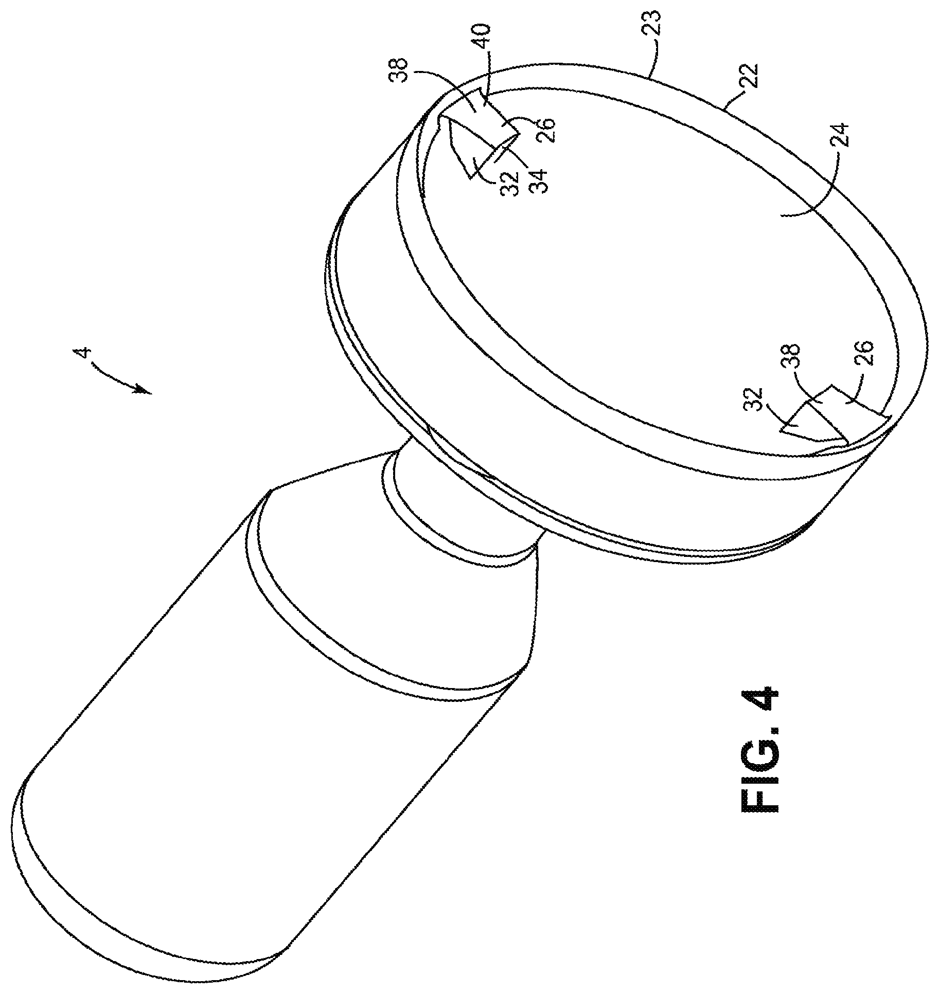
FIG. 4 is a perspective of an embodiment of a cutting element;
FIG. 5 is an enlarged end view of the cutting element;
FIG. 6 is a longitudinal section of the cutting element of FIG. 4;
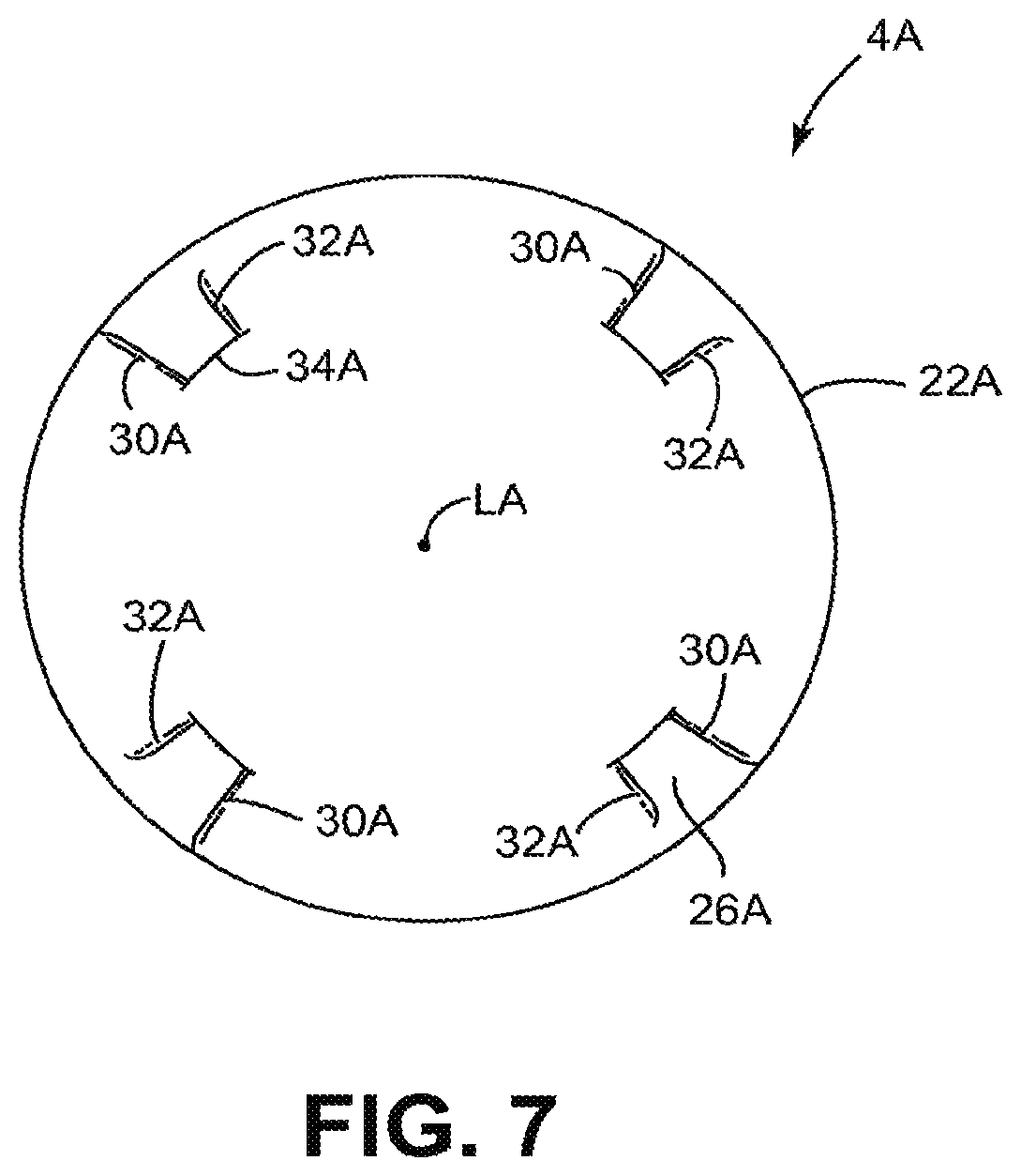
FIG. 7 is an end view of another embodiment of a cutting element, which may be used with the atherectomy catheter shown in FIG. 1;
FIG. 8 is a perspective of the cutting element of FIG. 7;
FIG. 8A is an enlarged detail of FIG. 8 showing one of the raised elements of the cutting element;
FIG. 9 is an end view of another embodiment of a cutting element, which may be used with the atherectomy catheter shown in FIG. 1;
FIG. 10 is a perspective of the embodiment of the cutting element illustrated in FIG. 9;
FIG. 10A is an enlarged detail of FIG. 10 showing of the raised elements of the cutting element embodiment;
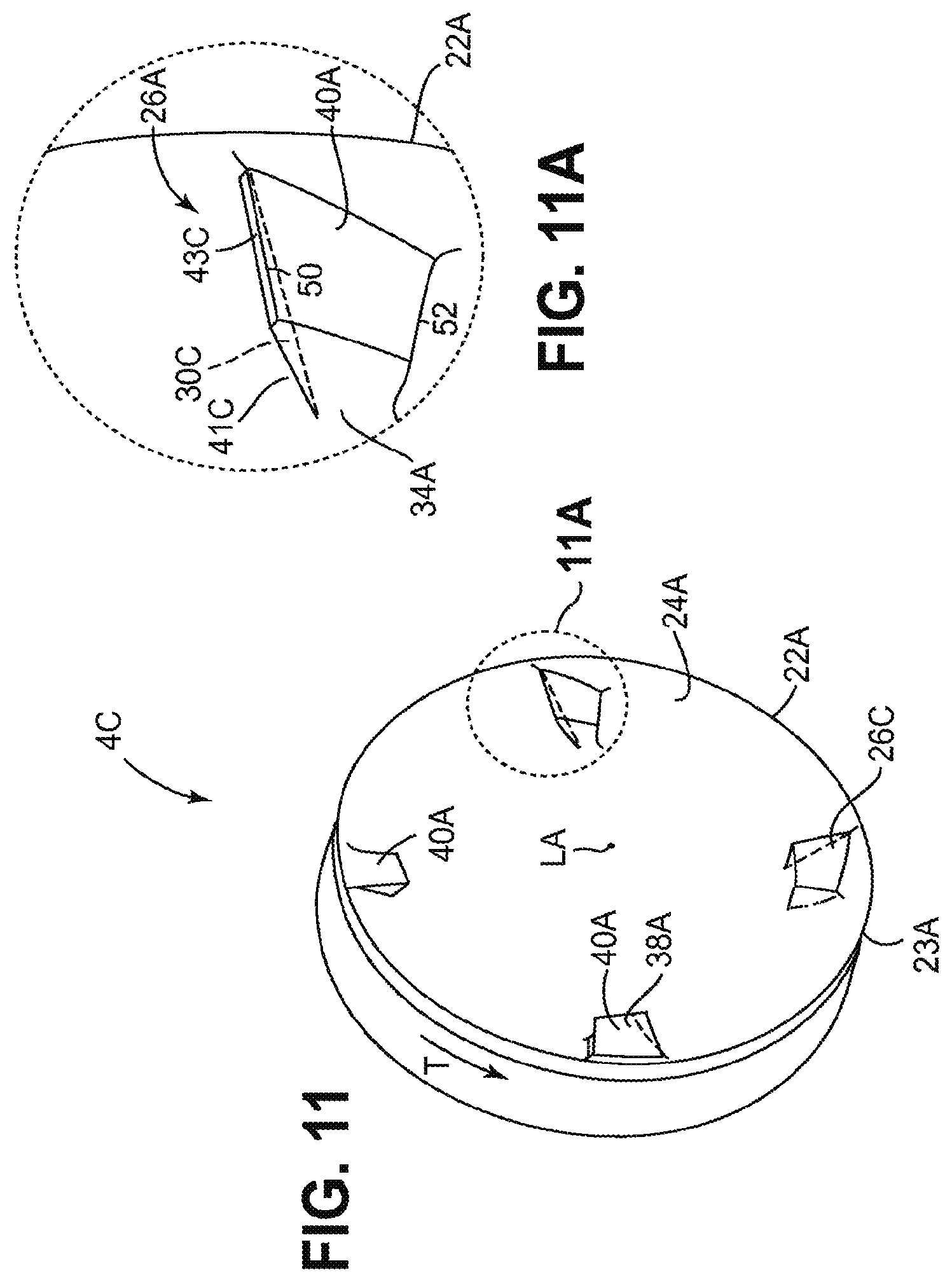
FIG. 11 is perspective of a modified version of the embodiment of the cutting element illustrated in FIG. 8;
FIG. 11A is an enlarged detail of FIG. 11 showing one of the raised elements;
FIG. 12 is a perspective of another embodiment of a cutting element;
FIG. 13 is an end view of the cutting element of FIG. 12;
FIG. 14 is similar to FIG. 13, but enlarged and including imaginary circles for determining radial distances and radial lengths;
FIG. 15 is an enlarged, fragmentary view of FIG. 14;
FIG. 16 is similar to FIG. 13, but including a schematic representation of the catheter body;
FIG. 17 is similar to FIG. 16, except the schematic representation of the catheter body is shown in phantom;
FIG. 18 is a fragmentary, longitudinal section of a catheter including the cutting element of FIG. 12 removing tissue from a body lumen;
FIG. 19 is a perspective of another embodiment of a cutting element;
FIG. 20 is a perspective of another embodiment of a cutting element;
FIG. 21 is a perspective of another embodiment of a cutting element;
FIG. 22 is an end view of the cutting element of FIG. 21;
FIG. 23 is an enlarged, fragmentary section of the cutting element taken in the plane containing the line 23-23 in FIG. 22;
FIG. 24 is an enlarged view of a raised element of the cutting element of FIG. 21; and
FIG. 25 is a further enlarged, fragmentary view of FIG. 23.
Corresponding reference characters indicate corresponding parts throughout the drawings.
DETAILED DESCRIPTION OF THE DRAWINGS
Referring now to the drawings, several embodiments of a tissue-removing catheter for removing tissue from a body lumen are disclosed. In particular, the illustrated catheter embodiments are suitable for removing tissue from a body lumen wall, and are particularly suitable for removing (i.e., excising) plaque tissue from a vessel wall (e.g., peripheral arterial or peripheral venous wall). Features of the disclosed embodiments, however, may also be suitable for treating chronic total occlusion (CTO) of blood vessels, particularly peripheral arteries, and stenoses of other body lumens and other hyperplastic and neoplastic conditions in other body lumens, such as the ureter, the biliary duct, respiratory passages, the pancreatic duct, the lymphatic duct, and the like. Neoplastic cell growth will often occur as a result of a tumor surrounding and intruding into a body lumen. Removal of such material can thus be beneficial to maintain patency of the body lumen. While the remaining discussion is directed toward catheters for removing tissue from and penetrating occlusions in blood vessels (e.g., atheromatous or thrombotic occlusive material in an artery, or other occlusions in veins), it will be appreciated that the teachings of the present disclosure apply equally to other types of tissue-removing catheters, including, but not limited to, catheters for penetrating and/or removing tissue from a variety of occlusive, stenotic, or hyperplastic material in a variety of body lumens.
Referring to FIGS. 1 to 4, an atherectomy catheter 2, which has a cutting element 4, which is used to cut material from a blood flow lumen. The catheter has an elongate body 8 having distal and proximal portions and being sized and shaped for insertion into a body lumen of a subject. The cutting element 4 is movable between a stored position (FIG. 2) and a cutting position (FIG. 3) relative to a window or opening 6 in the catheter body 8 adjacent the distal portion. The cutting element 8 moves outwardly relative to the opening 6 so that an exposed portion of the element 4 extends outside the body 8 through the opening 6. The cutting element 4 may be positioned relative to the body 8 and opening 6 so that less than 90 degrees of the cutting element 4 is exposed to cut tissue. Of course, more of the cutting element 4 may be exposed without departing from numerous aspects of the invention.
Catheter 2 may have a maximum size of 3, 4, 5, 6, 7, 8, 9, 10, or 12 French (1, 1.3, 1.7, 2, 2.3, 2.7, 3, 3.3, or 4 mm) and may have a working length ranging of 20, 30, 40, 60, 80, 100, 120, 150, 180 or 210 cm depending on the requirements of the anatomical location in which use of the catheter is contemplated. Cutter 4 preferably has a diameter slightly less than that of the maximum size of catheter 2, typically 0.010'' (0.025 cm), 0.015'' (0.038 cm), 0.020'' (0.051 cm), 0.025'' (0.064 cm) or 0.030'' (0.076 cm) less. However these relative dimensions are not meant to be limiting.
The catheter 2 is moved distally through a vessel with the cutting element 4 in the working or cutting position as described in further detail below. As the catheter 2 moves through the blood vessel, the tissue is cut by the cutting element 4 and is directed into a tissue chamber 12 positioned distal to the cutting element 4. The tissue chamber 12 may be somewhat elongate to accommodate the tissue that has been cut.
The cutting element 4 is moved proximally from the stored position so that a cam surface 14 on the cutting element 4 engages a ramp 16 on the body 8 of the catheter 2. The interaction between the cam surface 14 and the ramp 16 causes the cutting element 4 to move to the cutting position and also causes a tip 18 to deflect which tends to move the cutting element 4 toward the tissue to be cut.
The cutting element 4 is coupled to a drive shaft 20 that extends through a lumen 21 in the catheter 2. The cutting element 4 is rotated about a longitudinal axis LA when the drive shaft rotates about its longitudinal axis. The cutting element 4 is rotated at about 1 to 160,000 rpm but may be rotated at any other suitable speed depending upon the particular application.
Referring to FIGS. 2, 4 and 5, the cutting element 4 is shown. The term "along the longitudinal axis" as used herein shall mean the view of FIG. 5 that shows the distal end of the cutting element 4 when viewed in the direction of the longitudinal axis and/or the axis of rotation. The cutting element 4 has an annular cutting edge 22 that may be a continuous, uninterrupted, circular-shaped edge although it may also include ridges, teeth, serrations or other features without departing from the scope of the invention. The cutting edge 22 may be at a radially outer edge 23 of the cutting element 4 when the cutting element 4 is in the cutting position. A circumferential inner surface 25 of the cutting element 4 extends from the cutting edge 22 and is chamfered or beveled.
The cutting element 4 has an inner cup-shaped surface 24, which directs the tissue cut by the cutting edge 22 into the tissue chamber 12. In the illustrated embodiment, the circumferential inner surface 25 and the inner cup-shaped surface 24 define an internal cavity of the cutting element 4. The cup-shaped surface 24 may be a smooth and continuous surface free of through-holes, teeth, fins or other features, which disrupt the smooth nature of the surface 24 for at least half the distance from the longitudinal axis LA to the outer radius at the cutting edge 22. The cup-shaped surface 24 may also be free of any such features throughout an area of at least 300 degrees relative to the longitudinal axis LA.
Cutter 4 may be comprised of steel, tungsten carbide, tungsten carbide cobalt, tungsten carbide molybdenum, silicon carbide, silicon nitride, ceramic, amorphous metals or other materials and may be manufactured by methods including turning, grinding, sintering, electro-discharge machining (EDM), laser cutting, heat treating, precipitation hardening, casting or other methods.
Referring to FIGS. 4 to 6, one or more raised elements 26 extend outwardly from the cup-shaped surface 24 with FIG. 5 showing two raised elements 26. The raised element 26 is a small wedge of material that rises relatively abruptly from the cup-shaped surface 24. The raised element 26 has a first wall 30 and a second wall 32 that both extend radially and form an angle of about 20 degrees therebetween so that the two raised elements 26 together occupy an area of about 40 degrees and altogether may be less than 60 degrees. A third wall 34 extends between the radially inner portion of the first and second walls 30, 32. The raised element 26 helps to break up hard tissue and plaque by applying a relatively blunt force to the hard tissue or plaque since cutting such tissue with the cutting edge 22 is often not effective.
The raised elements 26 altogether occupy a relatively small part of the cup-shaped surface 24. The raised elements 26 together may occupy less than 5% of a surface area of the cutting element 4. The term "surface area of the cutting element" as used herein shall mean the surface area which is radially inward from the outer or cutting edge 22 and is exposed when viewed along the longitudinal axis LA. Stated another way, at least 95% of the surface area of the cutting element is a smooth cup-shaped surface when viewed along the longitudinal axis. However, the raised element surface area may occupy more of the total surface area of the cup. By sizing and positioning the raised element 26 in this manner, the raised element 26 does not interfere with the ability of the cutting element 4 to cut and re-direct tissue into the tissue chamber while still providing the ability to break up hard tissue and plaque with the raised element 26.
The raised element 26 may be recessed from the cutting edge 22 longitudinally and/or radially. The raised element 26 may be recessed longitudinally (along axis LA) from the cutting edge 0.0010 to 0.0020 inch (0.0025 to 0.0051 cm) and may be recessed about 0.0015 inch (0.0038 cm). The raised element 26 may be recessed radially from the cutting edge 22 by about the same amount. A distal wall 38 of the cutting element 4 forms a flat surface 40, which is perpendicular to the longitudinal axis LA so that the entire surface is recessed the same distance from the cutting edge. The distal wall 38 may take any other shape, such as a curved shape, or may be tilted, inclined or beveled as now described. The raised element may have other shapes, sizes and locations within the scope of the present invention.
Referring to FIGS. 7, 8 and 8A, another cutting element 4A is shown wherein the same or similar reference numbers refer to the same or similar structure and all discussion concerning the same or similar features of the cutting element 4 are equally applicable here unless noted otherwise. The cutting element 4A has a cutting edge 22A that may be a continuous, uninterrupted, circular-shaped edge although it may also include ridges, teeth, serrations or other features without departing from the scope of the invention. The cutting edge 22A may be at a radially outer edge 23A of the cutting element 4A when the cutting element 4A is in the cutting position. The cutting element 4A has a cup-shaped surface 24A that directs the tissue cut by the cutting edge 22A into the tissue chamber 12 (see FIG. 2). The cup-shaped surface 24A may be a substantially smooth and continuous surface as described above in connection with the cutting element 4.
One or more raised elements 26A extend outwardly from the cup-shaped surface 24A. FIG. 8 shows four raised elements 26A but may include any number such as 1, 2, 3, 4, 6 or 8 raised elements. The raised element 26A is a small wedge of material that rises relatively abruptly from the cup-shaped surface 24A. The raised element 26A has a first wall 30A and a second wall 32A which, in one embodiment, both extend radially and form an angle of about 1 to 30 degrees therebetween so that the four raised elements 26A together occupy an area of about 4 to 60 degrees and altogether may be less than 60 degrees. A third wall 34A extends between the radially inner portion of the first and second walls 30A, 32A. In some embodiments the raised elements 26A may occupy a relatively small part of the cup-shaped surface 24A and may be recessed from the cutting edge 22A in the manner described above in connection with the cutting element 4. In other embodiments at least 60%, 70%, 80% or 90% of the surface area of the cutting element is a smooth cup-shaped surface.
A distal wall 38A of the cutting element 4A has a surface 40A that forms an angle of about 30 to 90 degrees with respect to the longitudinal axis LA. The entire surface 40A may still be somewhat close to but recessed from the cutting edge 22A so that the entire surface 40A is at least 0.0010, 0.0020, 0.0030, 0.0040 or 0.0050 inches (0.0025, 0.0051, 0.0076, 0.0101, or 0.0127 cm) from the cutting edge. A leading edge 50 formed at the intersection of wall 30A and distal wall 38A is closer to the cutting edge 22A than an edge 52 formed at the intersection of wall 32A and distal wall 38A. The cutting element 4A may be rotated in either direction so that the raised edge 50 may be the leading or trailing edge. In some embodiments the raised edge may be 0.0010 to 0.0020 inch (0.0025 to 0.0051 cm) from the cutting edge. The raised elements 26A may all be formed in the same manner or may be different from one another. For example, some of the elements 26A could be angled in different directions so that two of the elements have the raised edge 50 as the leading edge and two of the elements 26A have the raised edge 50 as the trailing edge. The raised elements 26A may also subtend different angles, be of different heights or may have different radial lengths without departing from various aspects of the present invention.
Referring to FIGS. 9, 10 and 10A, another cutting element 4B is shown wherein the same or similar reference numbers refer to the same or similar structure and all discussion concerning the same or similar features of the cutting element 4 are equally applicable here unless noted otherwise. The cutting element 4B has a cutting edge 22B that may be a continuous, uninterrupted, circular-shaped edge although it may also include ridges, teeth, serrations or other features without departing from the scope of the invention. The cutting edge 22B may be at a radially outer edge 23B of the cutting element 4B when the cutting element 4B is in the cutting position. The cutting element 4B has a cup-shaped surface 24B that directs the tissue cut by the cutting edge 22B into the tissue chamber 12 (see FIG. 2). In one embodiment the cup-shaped surface 24B may be a substantially smooth and continuous surface as described above in connection with the cutting element 4.
One or more raised elements 26B, extend outwardly from the cup-shaped surface 24B. FIGS. 9 and 10 show four raised elements 26B but may include any number such as 1, 2, 3, 4, 6 or 8 raised elements. The raised element 26B is a small wedge of material that rises relatively abruptly from the cup-shaped surface 24B and which subtends an arc of about 1 to 30 degrees relative to axis LA, the four raised elements 26B subtending an arc of about 4 to 60 degrees altogether. The raised element 26B has a first wall 30B that extends between a curved leading edge 50B and cup-shaped surface 24B and also has a second wall 32B which extends radially relative to axis LA. A third wall 34B extends between the radially inner portion of the first and second walls 30B, 32B. In some embodiments the raised elements 26B may occupy a relative small part of the cup-shaped surface 24B and may be recessed from the cutting edge 22B in the manner described above in connection with the cutting element 4. In other embodiments at least 60%, 70%, 80% or 90% of the surface area of the cutting element is a smooth cup-shaped surface.
A distal wall 38B of the cutting element 4B has a surface 40B that forms an angle of less than 90 degrees with respect to the longitudinal axis LA. In some embodiments the surface 40B is angled such that edge 50B is more distal than edge 52B. The entire surface 40B may still be somewhat close to but recessed from the cutting edge 22B so that the entire surface 40B is from 0.0010 to 0.0050 inch (0.0025 to 0.0127 cm), including 0.0010, 0.0020, 0.0030, 0.0040 or 0.0050 inch (0.0025, 0.0051, 0.0076, 0.0101, or 0.0127 cm), from the cutting edge. An edge 50B formed at the intersection of wall 30B and distal wall 38B is closer to the cutting edge 22B than an edge 52B formed at the intersection of wall 32B and distal wall 38B. The included angle between wall 30B and surface 40B, in the vicinity of edge 50B, is greater than 90 degrees. The cutting element 4B may be rotated in either direction so that the raised edge 50B may be the leading or trailing edge. In one embodiment, the cutter 4B is rotated in the direction of arrow R so that edge 50B is the leading edge. Raised edges 50B, 52B may be 0.0010 to 0.0020 inch (0.0025 to 0.0051 cm) from the cutting edge. The raised elements 26B may all be formed in the same manner or may be different from one another. For example, some of the elements 26B could be angled in different directions so that two of the elements have the raised edge 50B as the leading edge and two of the elements 26A have the raised edge 50B as the trailing edge. The raised elements 26B may also subtend different angles, be of different heights or may have different radial lengths without departing from various aspects of the present invention.
In one embodiment cutter 4B is rotated in the direction of arrow R and pushed distally to force cup-shaped surface 24B and raised elements 26B into contact with material such as atheroma or plaque. Raised elements 26B will tend to concentrate cutting force along edge 50B due to relief angle between cutter axis LA and surface 40B. Cutter 4B will tend to scrape away material such as atheroma or plaque rather than cut into this material due to the obtuse included angle between wall 30B and surface 40B, in the vicinity of edge 50B. Material contacted by raised elements 26B will tend to be directed toward axis LA by surface 30B which curves from a relatively tangential angle near edge 22B to a relatively radial angle near edge 34B.
Referring to FIGS. 11 and 11A, another cutting element 4C is shown. Cutting element 4C is a modified version of cutting element 4A. The modification consists of adding an undercut 41C to the leading face of one or more raised element 26A, resulting in modified raised element 26C. When cutter 4C is rotated in the direction of arrow T the undercut directs particles of material into the concave cavity defined by cup-shaped surface 24A of the cutter, and towards axis LA of the cutter. Optionally an undercut can be applied to the leading face of one or more raised element 26, 26B of cutting elements 4, 4B respectively as well as to one or more raised elements 26A of cutting element 4A.
Undercut 41C is defined by wall 30C which is oriented at an acute angle to surface 40A, which intersects cup-shaped surface 24A, and which meets wall 34A. The plane of wall 30C also intersects axis LA at less than 5, 10, 15, or 20 degrees such that, when cutter 4C is spinning in direction T, particles of material tend to travel along wall 30C in directions away from cutting edge 22A and toward axis LA. In some embodiments wall 43C may be interspersed between the intersection of wall 30C and wall 40A. Wall 43C may be oriented at any desired rake angle, such as for example a negative rake angle where the raised element will tend to not dig in to material being cut.
Referring to FIGS. 12-18, another embodiment of a cutting element is indicated generally at 4D. The cutting element 4D is similar to cutting element 4B, except that, as explained below, radial lengths of the raised elements, generally indicated at 26D, are greater than radial lengths of the raised elements 26B of the cutting element 4B. The cutting element 4D has an annular cutting edge 22D that may be a continuous, uninterrupted, arcuate-shaped edge although it may also include ridges, teeth, serrations or other features without departing from the scope of the invention. In the illustrated embodiment, an inner surface of the cutting element 4D defines an internal cavity of the cutting element. The inner surface includes a circumferential inner surface 25D, which is chamfered or beveled, extending from the cutting edge 22, and a central cup-shaped surface 24D that directs the tissue cut by the cutting edge 22D into the tissue chamber 12 (see FIG. 2). The cutting edge 22D may be at a radially outer edge 23D of the cutting element 4D when the cutting element is in the cutting position. In one embodiment the cup-shaped surface 24D may be a substantially smooth and continuous surface as described above in connection with the cutting element 4. As disclosed in another embodiment below (FIGS. 19 and 20), the cup-shaped surface 24D may be abrasive. In other embodiments, a through opening (not shown) may extend longitudinally through the cup-shaped surface 24D to direct removed tissue proximally through the cutting element 4D.
The raised elements 26D extend generally longitudinally outward from the cup-shaped surface 24B, within the internal cavity of the cutting element 4D. The embodiment illustrated in FIGS. 12-18 includes four raised elements 26D, but the cutting element 4D may include any number such as 1, 2, 3, 4, 6 or 8 raised elements. Each raised element 26D is a small wedge of material that rises relatively abruptly from the inner surface (e.g., the cup-shaped surface 24D) and which subtends an arc of about 1 to 30 degrees relative to axis LA, the four raised elements 26D subtending an arc of about 4 to 60 degrees altogether. Referring to FIG. 13, each raised element 26D has a leading radial wall (broadly, a first wall) 30D, a trailing radial wall (broadly, a second wall) 32D, a radially inner end wall 34D (broadly, a third wall), and a distal wall (broadly, a fourth wall) 38D. The leading radial wall 30D has a depth extending longitudinally relative to the cutter 4D between the distal wall 38D and the cup-shaped surface 24D, and a radial length RL (FIG. 15) extending generally inward from adjacent the cutting edge 22D of the cutting element 4D, as explained in more detail below. The leading radial wall 30D is curved along its depth (i.e., curved longitudinally with respect to the cutting element 4D) and is also curved along its radial length RL. A leading edge 50D of the cutting element 26D is defined at the intersection of the leading radial wall 30D and the distal wall 38D. The leading edge 50D is curved radially relative to the cutter 4D. In some embodiments the raised elements 26D may occupy a relative small part of the cup-shaped surface 24D and may be recessed from the cutting edge 22D in the manner described above in connection with the cutting element 4. In other embodiments at least 60%, 70%, 80% or 90% of the surface area of the cutting element is a smooth cup-shaped surface.
The distal wall 38D of the cutting element 4D forms an angle of less than 90 degrees with respect to the longitudinal axis LA. In some embodiments the wall 38D is angled such that edge 50D is more distal than the edge defined at the intersection of the distal wall 38D and the trailing wall 32D. The entire distal wall 38D may adjacent to, but recessed longitudinally from, the cutting edge 22D so that the distal wall is spaced a minimum longitudinal distance from about 0.0010 to about 0.0050 inch (0.0025 to 0.0127 cm), including about 0.0010, about 0.0020, about 0.0030, about 0.0040 or about 0.0050 inch (0.0025, 0.0051, 0.0076, 0.0101, or 0.0127 cm), from the cutting edge. The included angle between leading radial wall 30D and the distal wall 38D, in the vicinity of the leading edge 50D, may be greater than 90 degrees. The cutting element 4D is rotated in the direction R (FIG. 13) so that the leading edge 50D engages the tissue to be removed. As shown in FIG. 15, the leading edge 50D of the raised element 26D may be spaced a radial distance d.sub.1 measuring from about 0.0010 to about 0.0020 inch (0.0025 to 0.0051 cm) from the cutting edge 22D. The raised elements 26D may all be formed in the same manner or may be different from one another. The raised elements 26D may also subtend different angles, be of different heights, have different radial lengths, or have a different spacing (including zero) from the cutting edge without departing from various aspects of the present invention.
Referring to FIGS. 14 and 15, the radial length RL of the leading radial wall 30D of each raised element 26D is defined by the radial distance between the radially outermost portion P1 and the radially innermost portion P2 of the leading radial wall. In FIG. 15, the radial length RL of the radial wall 30D is measured using concentric, outer and inner imaginary circles C1, C2, respectively, each having a center that is coincident with the longitudinal axis LA. The radially outermost portion P1 of the leading radial wall 30D lies on the circumference of the outer imaginary circle C1, and the radially innermost portion P2 lies on the circumference of the inner imaginary circle C2. In the illustrated embodiment, each radially outermost portion P1 of the leading radial walls 30D lies on the circumference of the same outer imaginary circle C1, and each radially innermost portion P2 lies on the circumference of the same inner imaginary circle C2, though it is understood that the radially outermost and innermost portions, respectively, may not lie on the same imaginary circles without departing from the scope of the present invention. In the illustrated embodiment, the radially inner end wall 34D is arcuately shaped so that substantially the entire radially inner end wall lies on the circumference of the inner imaginary circle C2, although this may not be the case in other embodiments. The radial distance between the circumferences of the outer and inner imaginary circles C1, C2, respectively, determines the radial length RL of the leading radial wall 30D, as shown in FIG. 15. In one example, the radial length RL of the leading radial wall 30D may measure from about 0.0050 in to about 0.0200 in, or from about 0.0075 in to about 0.0175 in, or from about 0.0100 in to about 0.0150 in. In one example, the radial length RL of the leading radial wall may be at least about 33%, or at least about 40%, or at least about 50%, or at least about 60% or at least about 70% or at least about 80% of the radius R (FIG. 15) of the cutting edge 22D.
Referring still to FIG. 15, the radially innermost portion P2 of the leading radial wall 30D of each raised element 26D is spaced a radial distance d.sub.2 from the longitudinal axis LA of the cutting element 4D. As set forth above, the radially innermost portion P2 of the leading radial wall 30D lies on the circumference of the inner imaginary circle C2. The radial distance between the longitudinal axis LA and the circumference of the inner imaginary circle C2 determines the radial distance d.sub.2 between the longitudinal axis and the radially innermost portion P2 of the leading radial wall 30D. In one example, radial distance d between the longitudinal axis and the radially innermost portion P2 of the leading radial wall 30D may measure from about 0.0150 in to about 0.0300 in, or from about 0.0175 in to about 0.0275 in, or from about 0.0200 in to about 0.0250 in. In one example, the radial distance d.sub.2 may be less than about 66%, or less than about 60%, or less than about 55%, or less than about 50%, or less than about 45%, or less than about 40%, or less than about 35% of the radius R of the annular cutting edge 22D, as shown in FIG. 15. In one example, the radial distance d.sub.2 may be from about 15% to about 66%, or from about 20% to about 60%, or from about 25% to about 50%, or from about 30% to about 40% of the radius R of the annular cutting edge 22D.
As disclosed above herein, in the deployed configuration the cutting element 4D extends through the window or opening 6 in the tip 18. In this embodiment, each raised element 26D is configured such that as the cutting element 4D is rotated 360 degrees, less than an entirety of the leading radial wall 30D is ever exposed through the opening 6. Stated another way, a radially outer portion of each raised element 26D is cyclically exposed through the opening 6 while a radial inner portion of the leading radial wall never passes through the opening (i.e., is never exposed). This feature is shown in FIG. 17, where the circle indicated by reference character S defines an outer surface of the tip 18 that is immediately adjacent the window 6 (see also, FIG. 16). As can be seen from FIG. 17, an imaginary line L is drawn to show the location where a radial portion of the cutting element 4D is at its maximum exposure outside the catheter body. However, as can be seen from this figure, a radial inner portion of the leading radial wall 30D of cutting element 26D at the imaginary line L does not cross the exposure plane EP and does not pass through the window 6.
The cutter 4D is rotated in the direction of arrow R and pushed distally to force cup-shaped surface 24D and raised elements 26D into contact with material such as atheroma or plaque. Raised elements 26D will tend to concentrate cutting force along edge 50D because of the negative rake angle of the leading radial wall 30D. Cutter 4D will tend to scrape away material such as atheroma or plaque rather than cut into this material due to the obtuse included angle between wall 30D and distal wall 38D, in the vicinity of edge 50D. Material contacted by raised elements 26D will tend to be directed toward axis LA by surface 30D which curves from a more circumferential extent near edge 22D to a more radial extent near edge 34D. Moreover, it is believed that configuring the raised element(s) 26D so that only a portion of the leading radial wall 30D intermittently passes through the window 6 (i.e., only a portion and not the entirety of the leading radial wall is exposed) and is intermittently exposed (as explained above), facilitates cutting and/or breaking of hardened tissue (e.g., calcified tissue) by ensuring that the raised elements 26D engage tissue that may enter the window 6, as shown in FIG. 18. The leading radial wall 30D also more reliably guides or directs removed material toward the axis LA.
The cutting element 4D may be formed in a suitable manner such as integrally as a single, one-piece construction. For example, the cutting element 4D may be comprised of steel, tungsten carbide, tungsten carbide cobalt, tungsten carbide molybdenum, silicon carbide, silicon nitride, ceramic, amorphous metals or other materials and may be manufactured by methods including turning, grinding, sintering, electro-discharge machining (EDM), laser cutting, heat treating, precipitation hardening, casting or other methods.
Referring to FIGS. 19 and 20, cutting elements 4E and 4F are shown (respectively). Cutting element 4E and 4F include raised elements 26E, 26F, that may be identical to the raised elements 26A-26D of any of the previously disclosed cutting element 4A-4D disclosed above or have a different configuration. Accordingly, the teachings of the raised elements 26A-26D set forth above are incorporated in this embodiment. As opposed to the previously disclosed cutting elements, the cutting elements 4E and 4F each has an abrasive cup-shaped surface 24E, 24F. In one embodiment, other than the abrasive cup-shaped surface 24E, 24F, the cutting elements 4E and 4F are identical to the cutting element 4D, including the raised elements 26E being identical to the raised elements 26D. Accordingly, in this embodiment each of the cutting elements 4E and 4F includes the cutting element 4D and the respective one of the abrasive cup-shaped surfaces 24E, 24F. Referring to FIG. 19, cutting element 4E includes the embossed area of the cup-shaped surface 24E, including raised, diamond-shaped abrading members 100. Referring to FIG. 20, cutting element 4F includes a dimpled area of the cup shape surface 24F including depressed portions 102. In each embodiment, the abrasive cup-shaped surface 24E, 24F abrades hardened tissue (e.g., calcified tissue), and in particular, the abrasive cup-shaped surface abrades hardened tissue that is not engaged by the raised elements 26E. Thus, it is believed that the cutting elements 4E and 4F may more effectively remove hardened tissue compared to the cutting element 4, which is free from an abrading surface.
The cutting elements 4E and 4F each may be formed integrally as a single, one-piece construction, or may be formed as a multiple-piece construction. As an example, each cutting element 4E and 4F may be comprised of steel, tungsten carbide, tungsten carbide cobalt, tungsten carbide molybdenum, silicon carbide, silicon nitride, ceramic, amorphous metals or other materials and may be manufactured by methods including turning, grinding, sintering, electro-discharge machining (EDM), laser cutting, heat treating, precipitation hardening, casting or other methods.
Referring to FIGS. 21-25, another embodiment of a cutting element is indicated generally at 4G. The cutting element 4G is similar to the cutting element 4B, and therefore, like components are indicated by similar reference numerals, and the teachings set forth with respect to the cutting element 4B apply equally to this embodiment. Briefly, each raised element 26G of the cutting element 4G has a leading wall 30G, a radial inner end wall 34G, a distal wall 38G, and a leading edge 50G. For purposes of this disclosure, the main difference between the present cutting element 4G and the prior cutting element 4B is that the radial distance between the leading edge 50G of each raised element 26G and the cutting edge 22G of the present cutting element 4G is greater than the radial distance between the leading edge 50B of each raised element 26B and the cutting edge 22B of the cutting element 4B. It is understood that the teachings set forth herein for the cutting element 4G apply equally to the other cutting elements 4A-4F.
In the illustrated example, the present cutting element 4G includes an undercut (e.g., groove, recess, notch or cutout) 106 in each of the raised elements 26G adjacent the cutting edge 22G. The undercut 106 extends through the leading wall 30G, the leading edge 50G, and the distal wall 38G of each raised element 26G. The undercut 106 extends generally radially into the raised element 26G at the radially outermost portion of the raised element. As best seen in FIG. 24, the undercut 106 has a circumferential extent almost perpendicular to the wall 30G. The depth of the undercut 106 shallows slightly circumferentially away from the leading edge 50G. In contrast, the undercut 41C of FIGS. 11 and 11A extends circumferentially into the raised element 26C and has a generally radial extent along the wall 30C. As shown best in FIG. 25, because of the undercut 106, the radially outermost portion P1 of the leading edge 50G of the cutting element 4G is radially spaced from the chamfered circumferential inner surface 25G (broadly, the inner surface) of the cutting element a radial distance D1 (FIG. 25). In one example, the radial distance D1 may measure from greater than 0.0000 in to about 0.0100 in, or from greater than 0.0000 to about 0.0050 in, or from about 0.0005 in to about 0.0015 in. The radially outermost portion P1 of the leading edge 50G is radially spaced from the cutting edge 22G of the cutting element 4G a distance D2, which is greater than the radial distance between the leading edge 50B and the cutting edge 22B of the cutting element 4B. In one example, the distance D2 may measure from greater than 0.0000 in to about 0.0100 in, or from greater than 0.0000 to about 0.0050 in, or from about 0.0005 in to about 0.0020 in. Moreover, the leading edge 50G of the cutting element 4G may be spaced a minimum longitudinal distance D3 from the cutting edge 22G. In one example, the distance D3 may measure from about 0.0000 to about 0.0020 in. In one example, the leading edge 50G is similar to the leading edge 50B, except for the undercut 106, and therefore, an imaginary extrapolated line extending from the leading edge 50G intersects the chamfered inner surface 25G of the cutting element 4G at portion P3 (FIG. 24), which may be substantially the same location as the radially outermost portion P1 of the raised element 26B (see, e.g., FIG. 14).
It is believed that by spacing the leading edges 50G of the raised elements 26G from the chamfered inner circumferential portion 25G of the cutting element 4G, while maintaining a suitable minimum longitudinal distance between the cutting edge 22G and the leading edges of the raised elements, the raised elements 26G have better engagement with tissue than the cutting element 4B, without sacrificing cutting efficiency of the cutting element.
The cutting elements 4G may be formed integrally as a single, one-piece construction, or may be formed as a multiple-piece construction. As an example, the cutting element 4G may be comprised of steel, tungsten carbide, tungsten carbide cobalt, tungsten carbide molybdenum, silicon carbide, silicon nitride, ceramic, amorphous metals or other materials and may be manufactured by methods including turning, grinding, sintering, electro-discharge machining (EDM), laser cutting, heat treating, precipitation hardening, casting or other methods.
Use of the catheter 2 is now described in connection with the cutting element 4 but is equally applicable to use of the catheter 2 with either the cutting element 4A, the cutting element 4B, or the cutting element 4C. The catheter 2 is introduced into the patient in a conventional manner using a guidewire (not shown) or the like. The catheter 2 is advanced with the cutting element in the stored position of FIG. 2 until the catheter is positioned proximal to the location where material is to be removed. The cutting element 4 is then moved proximally so that the ramp 16 and cam surface 14 engage to move the cutting element 4 to the cutting position of FIG. 3 and to deflect the tip of the catheter 2 to move the cutting element 4 toward the tissue to be cut. The cutting element 4 is rotated about longitudinal axis LA and catheter 2 is then moved distally through the vessel so that the cutting element 4 cuts tissue. The tissue, which has been cut, is directed into the tissue chamber 12 by the cup-shaped surface 24, one or more raised elements 26, by curved surface 30B (of cutting element 4B), or by any combination of a cup-shaped surface, raised element, or curved surface. The location for collection of cut tissue may be other than described within the scope of the present invention.
More specifically, when using cutting element 4B and rotating the cutting element in the direction of arrow R (FIG. 9) cutting edge 22B slices softer material and cup-shaped surface directs the cut material into tissue chamber 12; the relief angle assures that distally directed force on the catheter is concentrated at raised element edge 50B rather than distributed over wall 38B; raised elements 26B will tend to scrape away or pulverize harder material such as calcium due to the obtuse included angle between leading radial wall 30B and distal wall 38B in the vicinity of edge 50B; curved surface 30B directs material particles towards cutter axis LA; and curved surface 30B when rotating creates a fluid vortex that tends to direct material particles towards cutter axis LA and distally into tissue chamber 12.
More specifically, when using an undercut such as that shown for cutting element 4C and rotating the cutting element in the direction of arrow T (FIG. 11) undercut 41C directs material away from cutting edge 22A, along cup-shaped surface towards axis LA, and radially towards axis LA of the cutting element.
More specifically, when using the cutting element 4D with raised elements 26D having leading radial walls 30D as set forth above, the raised elements facilitate cutting and/or breaking of hardened tissue (e.g., calcified tissue) by ensuring that the raised elements 26D engage tissue that may enter the window 6, as shown in FIG. 18.
When using the cutting elements 4E or 4F, the abrasive cup-shaped surface 24E, 24F abrades hardened tissue (e.g., calcified tissue), and in particular, the abrasive cup-shaped surface abrades hardened tissue that is not engaged by the raised elements 26E.
When using the cutting element 4G, the raised elements 26G have improved engagement with tissue, as compared to the cutting element 4B, without sacrificing cutting efficiency of the cutting element.
Having described the invention in detail, it will be apparent that modifications and variations are possible without departing from the scope of the invention defined in the appended claims.
When introducing elements of the present invention or the preferred embodiments(s) thereof, the articles "a", "an", "the" and "said" are intended to mean that there are one or more of the elements. The terms "comprising", "including" and "having" are intended to be inclusive and mean that there may be additional elements other than the listed elements.
As various changes could be made in the above constructions, products, and methods without departing from the scope of the invention, it is intended that all matter contained in the above description and shown in the accompanying drawings shall be interpreted as illustrative and not in a limiting sense.
* * * * *
References
D00000
D00001
D00002
D00003
D00004
D00005
D00006
D00007
D00008
D00009
D00010
D00011
D00012
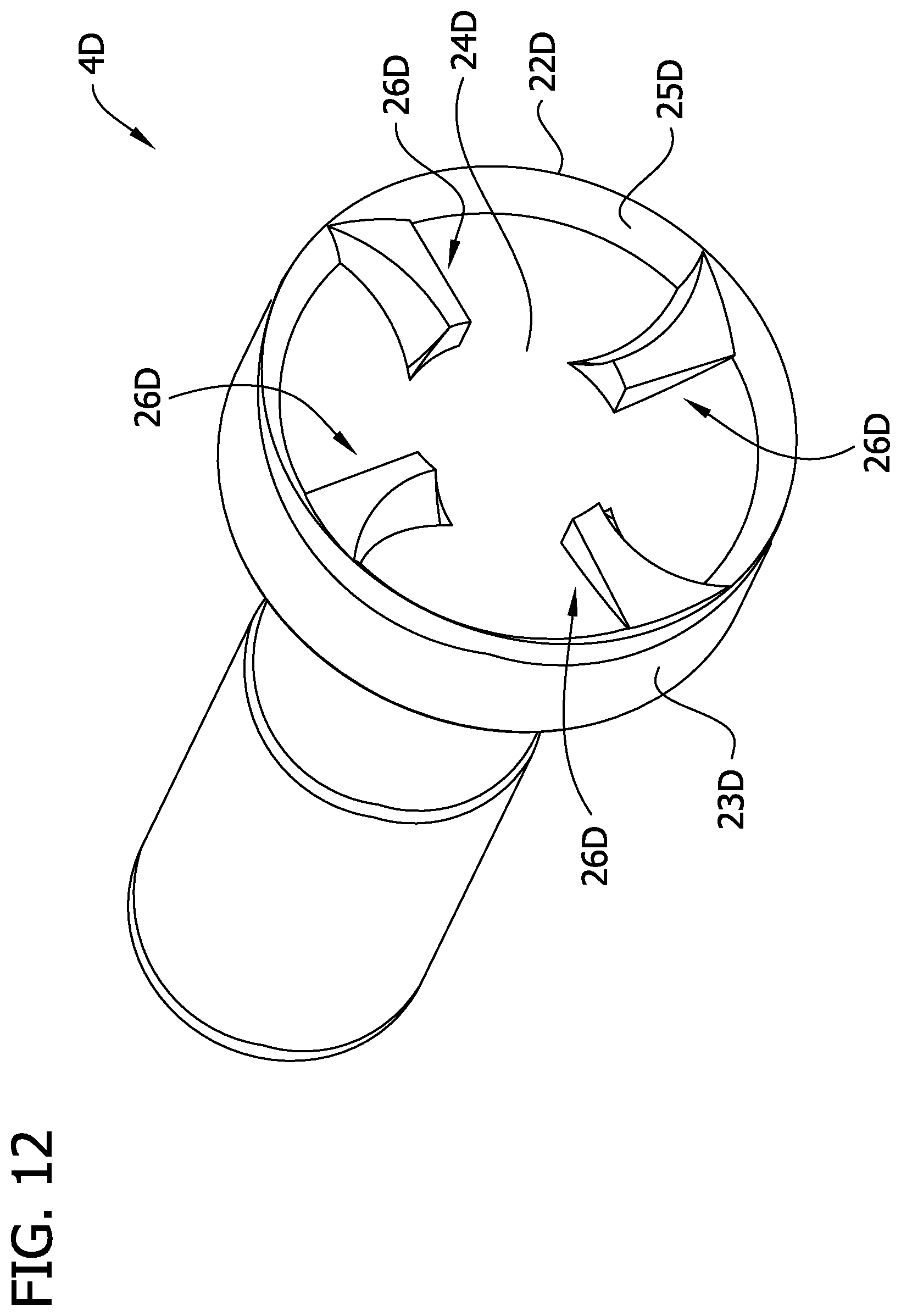
D00013
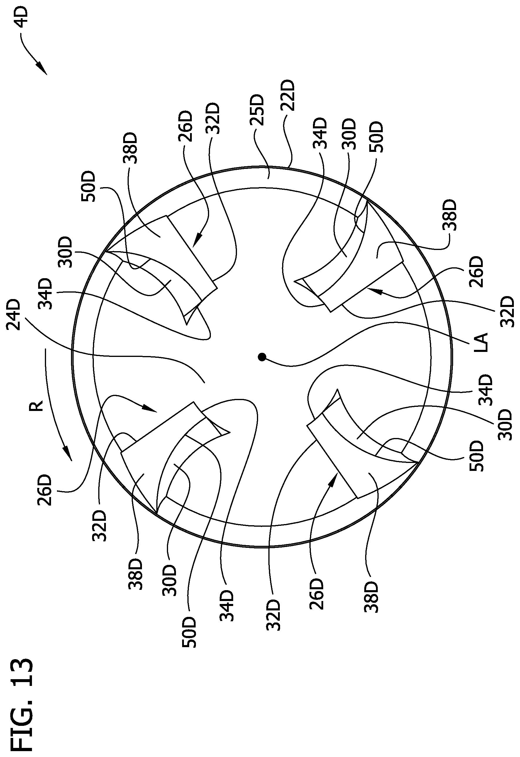
D00014

D00015

D00016
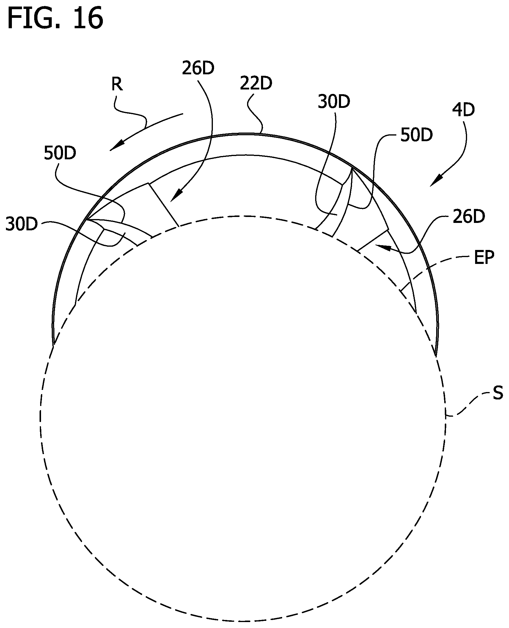
D00017

D00018

D00019

D00020

D00021
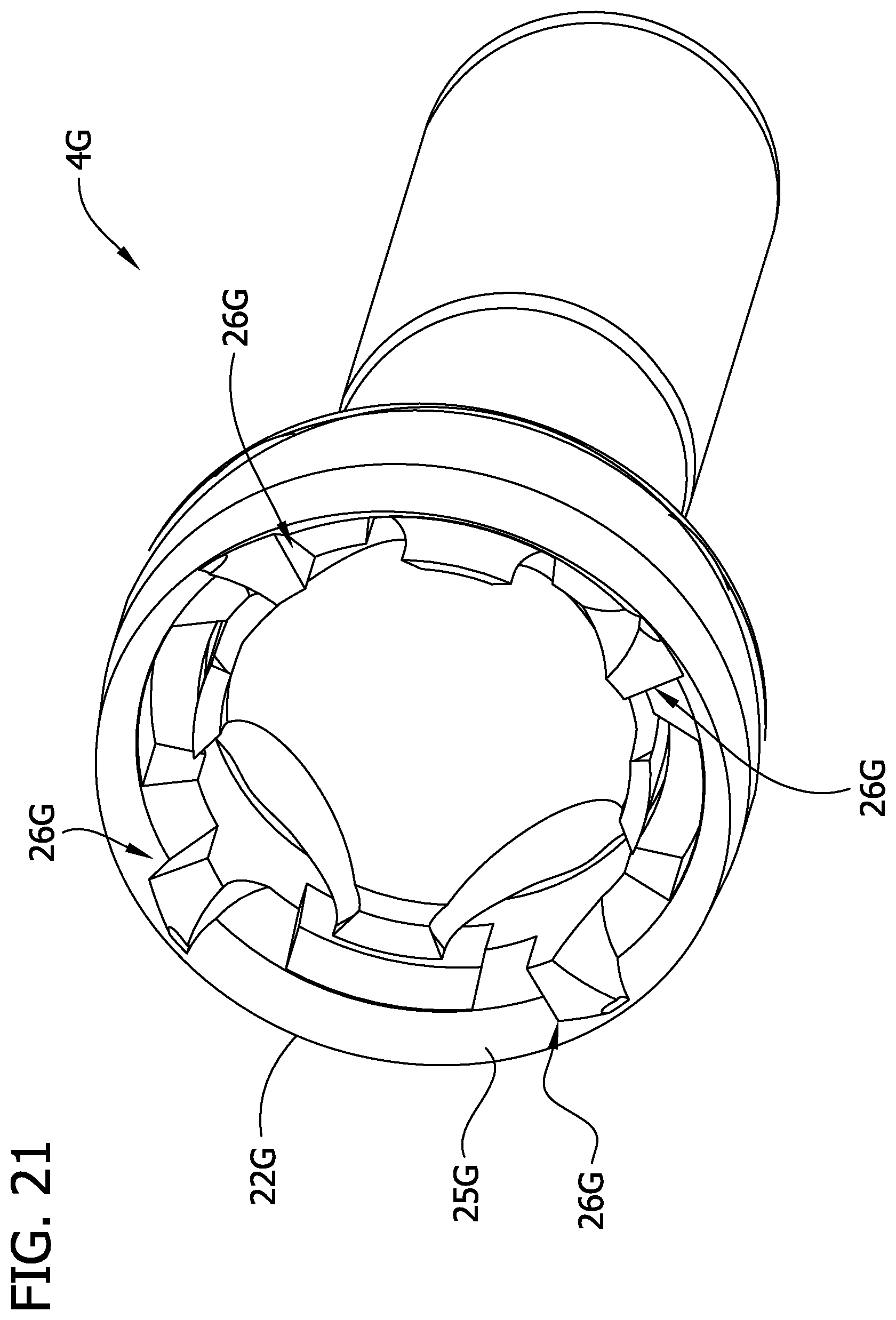
D00022

D00023

D00024

D00025
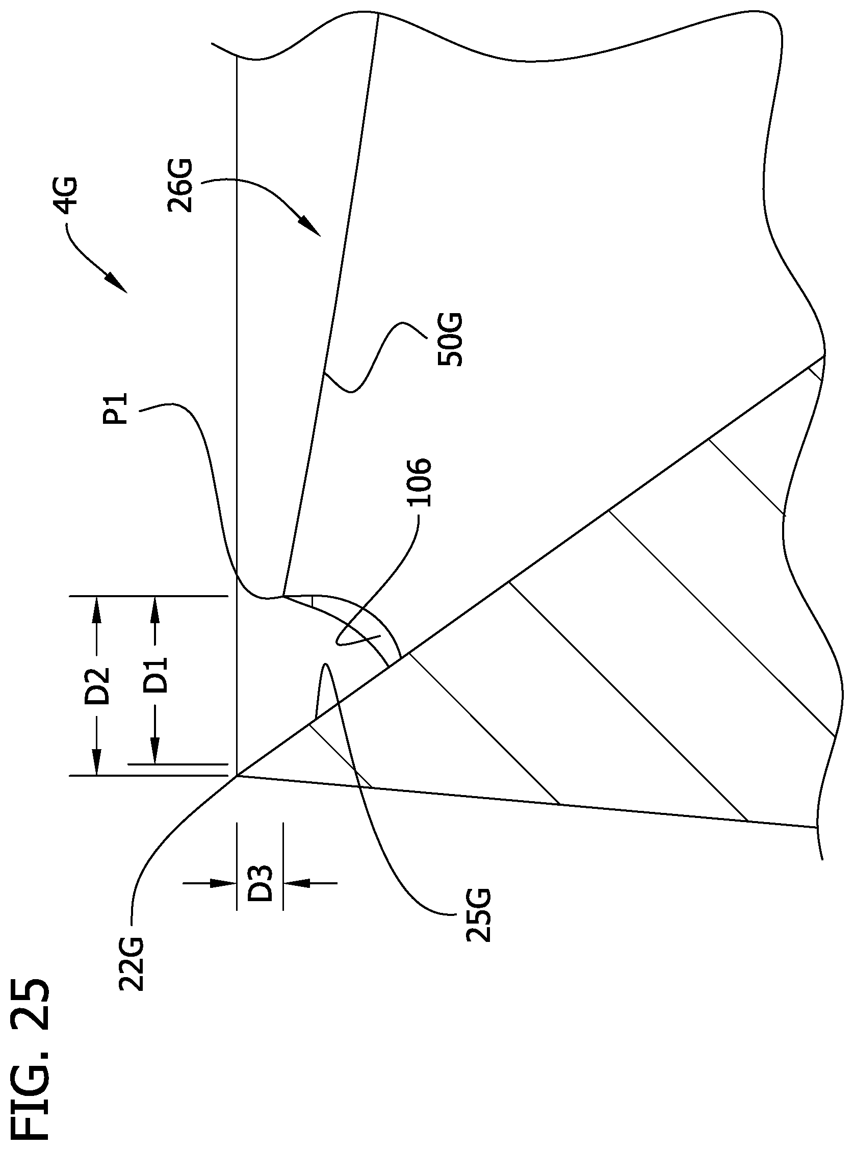
XML
uspto.report is an independent third-party trademark research tool that is not affiliated, endorsed, or sponsored by the United States Patent and Trademark Office (USPTO) or any other governmental organization. The information provided by uspto.report is based on publicly available data at the time of writing and is intended for informational purposes only.
While we strive to provide accurate and up-to-date information, we do not guarantee the accuracy, completeness, reliability, or suitability of the information displayed on this site. The use of this site is at your own risk. Any reliance you place on such information is therefore strictly at your own risk.
All official trademark data, including owner information, should be verified by visiting the official USPTO website at www.uspto.gov. This site is not intended to replace professional legal advice and should not be used as a substitute for consulting with a legal professional who is knowledgeable about trademark law.