Function disabler device and system
Pederson February 23, 2
U.S. patent number 10,932,337 [Application Number 16/601,183] was granted by the patent office on 2021-02-23 for function disabler device and system. This patent grant is currently assigned to Federal Law Enforcement Development Services, Inc.. The grantee listed for this patent is Federal Law Enforcement Development Services, Inc.. Invention is credited to John C. Pederson.

| United States Patent | 10,932,337 |
| Pederson | February 23, 2021 |
Function disabler device and system
Abstract
A function disabler system includes a personal electronic device having at least one component such as a camera, and a processor having pulsed light communication software enabling receipt and transmission of pulsed light communication signals. The processor additionally includes a hosting customer software application, where the personal electronic device receives at least one pulsed light communication signal within a designated area and the pulsed light communication signal includes an instruction signal which instructs the hosting customer software application to disable the at least one component when the personal electronic device is positioned in the designated area.
| Inventors: | Pederson; John C. (Merritt Island, FL) | ||||||||||
|---|---|---|---|---|---|---|---|---|---|---|---|
| Applicant: |
|
||||||||||
| Assignee: | Federal Law Enforcement Development
Services, Inc. (St. Cloud, MN) |
||||||||||
| Family ID: | 57994246 | ||||||||||
| Appl. No.: | 16/601,183 | ||||||||||
| Filed: | October 14, 2019 |
Prior Publication Data
| Document Identifier | Publication Date | |
|---|---|---|
| US 20200045790 A1 | Feb 6, 2020 | |
Related U.S. Patent Documents
| Application Number | Filing Date | Patent Number | Issue Date | ||
|---|---|---|---|---|---|
| 16210546 | Oct 15, 2019 | 10448472 | |||
| 15233282 | Aug 10, 2016 | ||||
| 62203697 | Aug 11, 2015 | ||||
| Current U.S. Class: | 1/1 |
| Current CPC Class: | H04B 10/116 (20130101); H05B 47/11 (20200101); H05B 45/10 (20200101); H05B 47/155 (20200101); H05B 47/105 (20200101); G08C 23/04 (20130101); H05B 45/20 (20200101); H05B 47/19 (20200101); H05B 47/115 (20200101); Y02B 20/40 (20130101); H05B 45/18 (20200101) |
| Current International Class: | H05B 45/10 (20200101); H05B 47/105 (20200101); H05B 47/155 (20200101); G08C 23/04 (20060101); H05B 47/11 (20200101); H05B 47/19 (20200101); H04B 10/116 (20130101); H05B 45/20 (20200101) |
References Cited [Referenced By]
U.S. Patent Documents
| 700678 | May 1902 | Downie |
| 2082279 | June 1937 | Fore |
| 3469686 | September 1969 | Gutsche et al. |
| 3696384 | October 1972 | Lester |
| 3701043 | October 1972 | Zuleeg et al. |
| 3705316 | December 1972 | Burrous et al. |
| 3863075 | January 1975 | Ironmonger et al. |
| 3867718 | February 1975 | Moe |
| 3889147 | June 1975 | Groves |
| 3911430 | October 1975 | Jankowski et al. |
| 4149111 | April 1979 | Coates, Jr. |
| 4243985 | January 1981 | Quayle |
| 4254453 | March 1981 | Mouyard |
| 4271408 | June 1981 | Teshima |
| 4298806 | November 1981 | Herold |
| 4301461 | November 1981 | Asano |
| 4319306 | March 1982 | Stanuch |
| 4336580 | June 1982 | Mouyard |
| 4342944 | August 1982 | SpringThorpe |
| 4368979 | January 1983 | Ruell |
| 4390931 | June 1983 | Gorick |
| 4434510 | February 1984 | Lemelson |
| 4445132 | April 1984 | Ichikawa |
| 4556862 | December 1985 | Meinershagen |
| 4595904 | June 1986 | Gosswiller |
| 4598198 | July 1986 | Fayfield |
| 4614866 | September 1986 | Liss |
| 4615131 | October 1986 | Wakatake |
| 4616225 | October 1986 | Woudenberg |
| 4630180 | December 1986 | Muraki |
| 4630183 | December 1986 | Fujita |
| 4633280 | December 1986 | Takasu |
| 4654629 | March 1987 | Bezos |
| 4703219 | October 1987 | Mesquida |
| 4710977 | December 1987 | Lemelson |
| 4716296 | December 1987 | Bussiere |
| 4720835 | January 1988 | Akiba |
| 4724312 | February 1988 | Snaper |
| 4742432 | May 1988 | Thillays |
| 4799135 | January 1989 | Inukai |
| 4821118 | April 1989 | Lafreniere |
| 4821338 | April 1989 | Naruse |
| 4848923 | July 1989 | Ziegler |
| 4868719 | September 1989 | Kouchi |
| 4900970 | February 1990 | Ando |
| 4918497 | April 1990 | Edmond |
| 4928084 | May 1990 | Reiser |
| 4929866 | May 1990 | Murata |
| 4935665 | June 1990 | Murata |
| 4949866 | August 1990 | Sanders |
| 4954822 | September 1990 | Borenstein |
| 4965644 | October 1990 | Kawabata |
| 4966862 | October 1990 | Edmond |
| 4975644 | December 1990 | Fox |
| 4975814 | December 1990 | Schairer |
| 4990970 | February 1991 | Fuller |
| 5000569 | March 1991 | Nylund |
| 5027168 | June 1991 | Edmond |
| 5035055 | July 1991 | McCullough |
| 5038406 | August 1991 | Titterton |
| 5041947 | August 1991 | Yuen |
| 5045767 | September 1991 | Wakatake |
| 5050055 | September 1991 | Lindsay |
| 5057828 | October 1991 | Rousseau |
| 5060303 | October 1991 | Wilmoth |
| 5062152 | October 1991 | Faulkner |
| 5067788 | November 1991 | Jannson |
| 5091828 | February 1992 | Jincks |
| D324921 | March 1992 | Stanuch |
| 5093768 | March 1992 | Ohe |
| 5097397 | March 1992 | Stanuch |
| 5097612 | March 1992 | Williams |
| 5099346 | March 1992 | Lee |
| 5101326 | March 1992 | Roney |
| 5122943 | June 1992 | Pugh |
| 5136287 | August 1992 | Borenstein |
| 5159486 | October 1992 | Webb |
| 5164992 | November 1992 | Turk |
| 5172113 | December 1992 | Hamer |
| 5182647 | January 1993 | Chang |
| 5187547 | February 1993 | Niina |
| 5193201 | March 1993 | Tymes |
| 5198746 | March 1993 | Gyugyi |
| 5198756 | March 1993 | Jenkins |
| 5220235 | June 1993 | Wakimizu |
| 5224773 | July 1993 | Arimura |
| 5233204 | August 1993 | Fletcher |
| 5235498 | August 1993 | VanDulmen |
| 5247380 | September 1993 | Lee |
| 5283425 | February 1994 | Imamura |
| 5291196 | March 1994 | Defour |
| 5296840 | March 1994 | Gieffers |
| 5298738 | March 1994 | Gebert |
| 5302965 | April 1994 | Belcher |
| 5313187 | May 1994 | Choi |
| 5321593 | June 1994 | Moates |
| 5357123 | October 1994 | Sugawara |
| 5357409 | October 1994 | Glatt |
| 5359255 | October 1994 | Kawai |
| 5359669 | October 1994 | Shanley |
| 5361190 | November 1994 | Roberts |
| 5362971 | November 1994 | McMahon |
| 5381155 | January 1995 | Gerber |
| 5400140 | March 1995 | Johnston |
| 5401328 | March 1995 | Schmitz |
| 5403916 | April 1995 | Watanabe |
| 5406095 | April 1995 | Koyama |
| 5410328 | April 1995 | Yoksza |
| 5410453 | April 1995 | Ruskouski |
| 5416627 | May 1995 | Wilmoth |
| 5419065 | May 1995 | Lin |
| 5420444 | May 1995 | Sawase |
| 5422623 | June 1995 | Bader |
| 5426417 | June 1995 | Stanuch |
| 5434693 | July 1995 | Tanaka |
| 5436809 | July 1995 | Brassier |
| 5450301 | September 1995 | Waltz |
| 5453729 | September 1995 | Chu |
| 5465142 | November 1995 | Krumes |
| 5471371 | November 1995 | Koppolu |
| 5475241 | December 1995 | Harrah |
| 5482896 | January 1996 | Tang |
| 5490048 | February 1996 | Brassier |
| 5490049 | February 1996 | Montalan |
| 5491350 | February 1996 | Unno |
| 5495358 | February 1996 | Bartig |
| 5498883 | March 1996 | Lebby |
| 5514627 | May 1996 | Lowery |
| 5516727 | May 1996 | Broom |
| 5519720 | May 1996 | Hirano |
| 5526237 | June 1996 | Davenport |
| 5528474 | June 1996 | Roney |
| 5532472 | July 1996 | Furuta |
| 5546219 | August 1996 | Iida |
| 5546496 | August 1996 | Kimoto |
| 5552780 | September 1996 | Knockeart |
| 5557257 | September 1996 | Gieffers |
| 5566022 | October 1996 | Segev |
| 5567036 | October 1996 | Theobald |
| 5568406 | October 1996 | Gerber |
| 5569939 | October 1996 | Choi |
| 5575459 | November 1996 | Anderson |
| 5580156 | December 1996 | Suzuki |
| 5585783 | December 1996 | Hall |
| 5593223 | January 1997 | Koizumi |
| 5593459 | January 1997 | Gamblin |
| 5594415 | January 1997 | Ishikawa |
| 5598290 | January 1997 | Tanaka |
| 5604480 | February 1997 | Lamparter |
| 5606444 | February 1997 | Johnson |
| 5607788 | March 1997 | Tomazic |
| 5612201 | March 1997 | DePlaen |
| 5612231 | March 1997 | Holm |
| 5625201 | April 1997 | Holm |
| 5627851 | May 1997 | Takahashi |
| 5631474 | May 1997 | Saitoh |
| 5632551 | May 1997 | Roney |
| 5633629 | May 1997 | Hochstein |
| 5634287 | June 1997 | Lamparter |
| 5634357 | June 1997 | Nutter |
| 5634711 | June 1997 | Kennedy |
| 5635902 | June 1997 | Hochstein |
| 5635981 | June 1997 | Ribacoff |
| 5636916 | June 1997 | Sokolowski |
| 5643357 | July 1997 | Breton |
| 5644291 | July 1997 | Jozwik |
| 5656829 | August 1997 | Sakaguchi |
| 5660461 | August 1997 | Ignatius |
| 5661645 | August 1997 | Hochstein |
| 5661742 | August 1997 | Huang |
| 5664448 | September 1997 | Swan |
| 5674000 | October 1997 | Kalley |
| 5694112 | December 1997 | VannRox |
| 5696500 | December 1997 | Diem |
| 5697175 | December 1997 | Schwartz |
| 5705047 | January 1998 | Lee |
| 5707891 | January 1998 | Izumi |
| 5708428 | January 1998 | Phillips |
| 5722760 | March 1998 | Chien |
| 5726535 | March 1998 | Yan |
| 5726786 | March 1998 | Heflinger |
| 5734337 | March 1998 | Kupersmit |
| 5734343 | March 1998 | Urbish |
| 5736925 | April 1998 | Knauff |
| 5739552 | April 1998 | Kimura |
| 5739592 | April 1998 | Rigsby |
| 5758947 | June 1998 | Glatt |
| 5760531 | June 1998 | Pederson |
| 5781105 | July 1998 | Bitar |
| 5783909 | July 1998 | Hochstein |
| 5785418 | July 1998 | Hochstein |
| 5786918 | July 1998 | Suzuki |
| 5789768 | August 1998 | Lee |
| 5793062 | August 1998 | Kish, Jr. |
| 5796376 | August 1998 | Banks |
| 5804822 | September 1998 | Brass |
| 5805081 | September 1998 | Fikacek |
| 5805209 | September 1998 | Yuge |
| 5806965 | September 1998 | Deese |
| 5808592 | September 1998 | Mizutani |
| 5809161 | September 1998 | Auty |
| 5809681 | September 1998 | Miyamoto |
| 5810833 | September 1998 | Brady |
| 5818421 | October 1998 | Ogino |
| 5826965 | October 1998 | Lyons |
| 5828055 | October 1998 | Jebens |
| 5831155 | November 1998 | Hewitt |
| 5838024 | November 1998 | Masuda |
| 5838116 | November 1998 | Katyl |
| 5838247 | November 1998 | Bladowski |
| 5838259 | November 1998 | Tonkin |
| 5848837 | December 1998 | Gustafson |
| 5860135 | January 1999 | Sugita |
| 5872646 | February 1999 | Alderman |
| 5875261 | February 1999 | Fitzpatrick |
| 5884997 | March 1999 | Stanuch |
| 5898381 | April 1999 | Gartner |
| 5900850 | May 1999 | Bailey |
| 5917637 | June 1999 | Ishikawa |
| 5929788 | July 1999 | Vukosic |
| 5931562 | August 1999 | Arato |
| 5931570 | August 1999 | Yamuro |
| 5932860 | August 1999 | Plesko |
| 5934694 | August 1999 | Schugt |
| 5936417 | August 1999 | Nagata |
| 5939996 | August 1999 | Kniveton |
| 5948038 | September 1999 | Daly |
| 5959752 | September 1999 | Ota |
| 5960135 | September 1999 | Ozawa |
| 5965879 | October 1999 | Leviton |
| 5966073 | October 1999 | Walton |
| 5975714 | November 1999 | Vetorino |
| 5990802 | November 1999 | Maskeny |
| 5991085 | November 1999 | Rallison |
| 6009650 | January 2000 | Lamparter |
| 6014237 | January 2000 | Abeles |
| 6018899 | February 2000 | Hanitz |
| 6028694 | February 2000 | Schmidt |
| 6035053 | March 2000 | Yoshioka |
| 6035055 | March 2000 | Wang |
| 6035074 | March 2000 | Fujimoto |
| 6064303 | May 2000 | Klein |
| 6067010 | May 2000 | Wang |
| 6067011 | May 2000 | Leslie |
| 6067018 | May 2000 | Skelton |
| 6072893 | June 2000 | Luo |
| 6081206 | June 2000 | Kielland |
| 6081304 | June 2000 | Kuriyama |
| 6086229 | July 2000 | Pastrick |
| 6091025 | July 2000 | Cotter |
| 6094148 | July 2000 | Henry |
| 6095661 | August 2000 | Lebens |
| 6095663 | August 2000 | Pond |
| 6102696 | August 2000 | Osterwalder |
| 6106137 | August 2000 | Adams |
| 6107918 | August 2000 | Klein |
| 6111671 | August 2000 | Bahuguna |
| 6118388 | September 2000 | Morrison |
| 6121898 | September 2000 | Moetteli |
| 6126087 | October 2000 | Hedger |
| 6159005 | December 2000 | Herold |
| 6166496 | December 2000 | Lys |
| 6177678 | January 2001 | Brass |
| 6183100 | February 2001 | Suckow |
| 6188738 | February 2001 | Sakamoto |
| 6243492 | June 2001 | Kamei |
| 6249340 | June 2001 | Jung |
| 6268788 | July 2001 | Gray |
| 6271814 | August 2001 | Kaoh |
| 6271815 | August 2001 | Yang |
| 6271913 | August 2001 | Jung |
| 6292575 | September 2001 | Bortolussi |
| 6293904 | September 2001 | Blazey |
| 6318886 | November 2001 | Stopa |
| 6352358 | March 2002 | Lieberman |
| 6367949 | April 2002 | Pederson |
| 6369849 | April 2002 | Rzyski |
| 6377558 | April 2002 | Dent |
| 6380865 | April 2002 | Pederson |
| 6389115 | May 2002 | Swistock |
| 6389155 | May 2002 | Funayama |
| 6396954 | May 2002 | Kondo |
| 6400828 | June 2002 | Covell |
| 6411022 | June 2002 | Machida |
| 6424269 | July 2002 | Pederson |
| 6426599 | July 2002 | Leeb |
| 6461008 | October 2002 | Pederson |
| 6462669 | October 2002 | Pederson |
| 6469631 | October 2002 | Pederson |
| 6472996 | October 2002 | Pederson |
| 6476726 | November 2002 | Pederson |
| 6504487 | January 2003 | Pederson |
| 6504646 | January 2003 | Amoruso |
| 6532212 | March 2003 | Soloway |
| 6547410 | April 2003 | Pederson |
| 6548967 | April 2003 | Dowling |
| 6590343 | July 2003 | Pederson |
| 6590502 | July 2003 | Pederson |
| 6600274 | July 2003 | Hughes |
| 6600899 | July 2003 | Radomsky |
| 6614359 | September 2003 | Pederson |
| 6623151 | September 2003 | Pederson |
| 6683590 | January 2004 | Pang |
| 6690294 | February 2004 | Zierden |
| 6693551 | February 2004 | Pederson |
| 6705745 | March 2004 | Pederson |
| 6707389 | March 2004 | Pederson |
| 6788217 | September 2004 | Pederson |
| 6814459 | November 2004 | Pederson |
| 6819654 | November 2004 | Soloway |
| 6819677 | November 2004 | Nouzovsky |
| 6822578 | November 2004 | Pederson |
| 6844824 | January 2005 | Vukosic |
| 6879263 | April 2005 | Pederson |
| 6892942 | May 2005 | Widl |
| 7006768 | February 2006 | Franklin |
| 7023469 | April 2006 | Olson |
| 7046160 | May 2006 | Pederson |
| 7102665 | September 2006 | Chandler |
| 7103614 | September 2006 | Kucik |
| 7178941 | February 2007 | Roberge |
| 7183895 | February 2007 | Bazakos |
| 7230884 | June 2007 | Shemesh |
| 7269632 | September 2007 | Edeker |
| 7289731 | October 2007 | Thinguldstad |
| 7309965 | December 2007 | Dowling |
| 7321757 | January 2008 | Yamashita |
| 7323991 | January 2008 | Eckert |
| 7324757 | January 2008 | Wilson |
| 7333735 | February 2008 | Goorjian |
| 7352972 | April 2008 | Franklin |
| 7439847 | October 2008 | Pederson |
| 7439874 | October 2008 | Sotiriou |
| 7529488 | May 2009 | Burdick |
| 7548698 | June 2009 | Yamamoto |
| 7557521 | July 2009 | Lys |
| 7567844 | July 2009 | Thomas |
| 7570246 | August 2009 | Maniam |
| 7583901 | September 2009 | Nakagawa |
| 7689130 | March 2010 | Ashdown |
| 7715723 | May 2010 | Kagawa |
| 7912377 | March 2011 | Koga |
| 7940191 | May 2011 | Hierzer |
| 8126554 | February 2012 | Kane |
| 8175799 | May 2012 | Woehler |
| 8188878 | May 2012 | Pederson |
| 8188879 | May 2012 | Pederson |
| 8207821 | June 2012 | Roberge |
| 8421588 | April 2013 | Ross |
| 8538692 | September 2013 | Wurman |
| 8547036 | October 2013 | Tran |
| 8571411 | October 2013 | Pederson |
| 8593299 | November 2013 | Pederson |
| 8687965 | April 2014 | Pederson |
| 8729833 | May 2014 | Chemel |
| 8744267 | June 2014 | Pederson |
| 8836922 | September 2014 | Pennecot |
| 8886045 | November 2014 | Pederson |
| 8890773 | November 2014 | Pederson |
| 8891962 | November 2014 | Du |
| 8902076 | December 2014 | Pederson |
| 8965460 | February 2015 | Rao |
| 9349217 | May 2016 | Worley, III et al. |
| 9413469 | August 2016 | Eden |
| 9461748 | October 2016 | Pederson |
| 9654163 | May 2017 | Pederson |
| 10251243 | April 2019 | Pederson |
| 10411746 | September 2019 | Pederson |
| 2002/0054411 | May 2002 | Heminger |
| 2002/0060522 | May 2002 | Stam |
| 2002/0109892 | August 2002 | Seto |
| 2002/0163448 | November 2002 | Bachinski |
| 2002/0168958 | November 2002 | Ford |
| 2002/0181044 | December 2002 | Kuykendall, Jr. |
| 2003/0025608 | February 2003 | Pederson |
| 2003/0107748 | June 2003 | Lee |
| 2003/0118216 | June 2003 | Goldberg |
| 2003/0156037 | August 2003 | Pederson |
| 2003/0169164 | September 2003 | Lau |
| 2003/0185340 | October 2003 | Frantz |
| 2003/0212996 | November 2003 | Wolzien |
| 2003/0222587 | December 2003 | Dowling |
| 2004/0028349 | February 2004 | Nagasaka |
| 2004/0044709 | March 2004 | Cabrera |
| 2004/0101312 | May 2004 | Cabrera |
| 2004/0151344 | August 2004 | Farmer |
| 2004/0153229 | August 2004 | Gokturk |
| 2004/0208599 | October 2004 | Swartz |
| 2005/0002673 | January 2005 | Okano |
| 2005/0005794 | January 2005 | Inukai |
| 2005/0057941 | March 2005 | Pederson |
| 2005/0111533 | May 2005 | Berkman |
| 2005/0111700 | May 2005 | OBoyle |
| 2005/0128751 | June 2005 | Roberge |
| 2005/0169643 | August 2005 | Franklin |
| 2005/0231128 | October 2005 | Franklin |
| 2005/0243173 | November 2005 | Levine |
| 2005/0252984 | November 2005 | Ahmed |
| 2006/0012315 | January 2006 | McDonough |
| 2006/0039698 | February 2006 | Pautler |
| 2006/0054776 | March 2006 | Nishimura |
| 2006/0056855 | March 2006 | Nakagawa |
| 2006/0132382 | June 2006 | Jannard |
| 2006/0149813 | July 2006 | Janik |
| 2006/0192672 | August 2006 | Gidge |
| 2006/0193634 | August 2006 | Wang |
| 2006/0213731 | September 2006 | Lesesky |
| 2006/0238368 | October 2006 | Pederson |
| 2006/0239689 | October 2006 | Ashdown |
| 2006/0253598 | November 2006 | Nakamura |
| 2006/0262545 | November 2006 | Piepgras |
| 2006/0275040 | December 2006 | Franklin |
| 2007/0041732 | February 2007 | Oki |
| 2007/0086912 | April 2007 | Dowling |
| 2007/0098407 | May 2007 | Hebrank |
| 2007/0104239 | May 2007 | Koga |
| 2007/0110446 | May 2007 | Hong |
| 2007/0145915 | June 2007 | Roberge |
| 2007/0147843 | June 2007 | Fujiwara |
| 2007/0160373 | July 2007 | Biegelsen |
| 2007/0165244 | July 2007 | Yukhin |
| 2007/0195263 | August 2007 | Shimizu |
| 2007/0219645 | September 2007 | Thomas |
| 2007/0258718 | November 2007 | Furlong |
| 2007/0269219 | November 2007 | Teller |
| 2007/0285026 | December 2007 | Johler |
| 2007/0294029 | December 2007 | DAndrea |
| 2008/0044188 | February 2008 | Kagawa |
| 2008/0063404 | March 2008 | Broyde |
| 2008/0074872 | March 2008 | Panotopoulos |
| 2008/0128505 | June 2008 | Challa |
| 2008/0129219 | June 2008 | Smith |
| 2008/0138077 | June 2008 | Stretton |
| 2008/0154101 | June 2008 | Jain |
| 2008/0170536 | July 2008 | Marshack |
| 2008/0214219 | September 2008 | Matsushima |
| 2008/0227463 | September 2008 | Hizume |
| 2008/0292320 | November 2008 | Pederson |
| 2008/0310850 | December 2008 | Pederson |
| 2009/0002265 | January 2009 | Kitaoka |
| 2009/0102396 | April 2009 | Petrucci |
| 2009/0129782 | May 2009 | Pederson |
| 2009/0157545 | June 2009 | Mobley |
| 2009/0226176 | September 2009 | Franklin |
| 2009/0262760 | October 2009 | Krupkin |
| 2009/0315481 | December 2009 | Zhao |
| 2009/0315485 | December 2009 | Verfuerth |
| 2010/0060194 | March 2010 | Furry |
| 2010/0111538 | May 2010 | Arita |
| 2010/0124412 | May 2010 | King |
| 2010/0142965 | June 2010 | Breyer |
| 2010/0188846 | July 2010 | Oda |
| 2010/0209105 | August 2010 | Shin |
| 2010/0270933 | October 2010 | Chemel |
| 2011/0006898 | January 2011 | Kruest |
| 2011/0007938 | January 2011 | Haynes |
| 2011/0018465 | January 2011 | Ashdown |
| 2011/0029897 | February 2011 | Russell |
| 2011/0037712 | February 2011 | Kim |
| 2011/0063522 | March 2011 | Karaoguz |
| 2011/0121754 | May 2011 | Shteynberg |
| 2011/0128384 | June 2011 | Tiscareno |
| 2011/0140612 | June 2011 | Mohan |
| 2011/0202151 | August 2011 | Covaro |
| 2011/0208963 | August 2011 | Soffer |
| 2011/0225611 | September 2011 | Shintani |
| 2011/0294465 | December 2011 | Inselberg |
| 2011/0305460 | December 2011 | Snyder |
| 2012/0138420 | June 2012 | Leibu |
| 2012/0179983 | July 2012 | Lemire |
| 2012/0183301 | July 2012 | Pederson |
| 2012/0202520 | August 2012 | George |
| 2012/0230696 | September 2012 | Pederson |
| 2012/0240196 | September 2012 | Bhagwat |
| 2012/0251100 | October 2012 | Rope |
| 2013/0015785 | January 2013 | Kamada |
| 2013/0094863 | April 2013 | Pederson |
| 2013/0145610 | June 2013 | Feri |
| 2013/0201316 | August 2013 | Binder |
| 2013/0221848 | August 2013 | Miesak |
| 2013/0229346 | September 2013 | Jungbauer |
| 2013/0229492 | September 2013 | Ose |
| 2013/0341062 | December 2013 | Paquin |
| 2014/0153923 | June 2014 | Casaccia |
| 2014/0213234 | July 2014 | Inselberg |
| 2014/0247907 | September 2014 | McCune |
| 2014/0284390 | September 2014 | Teng |
| 2014/0286644 | September 2014 | Oshima |
| 2014/0341588 | November 2014 | Pederson |
| 2015/0078743 | March 2015 | Yang |
| 2015/0228419 | August 2015 | Fadell |
| 2016/0190807 | June 2016 | Wendt |
| 2017/0367164 | December 2017 | Engelen |
| 2006201345 | Oct 2007 | AU | |||
| 2007202909 | Feb 2008 | AU | |||
| 2164920 | Jun 1996 | CA | |||
| 4304216 | Aug 1994 | DE | |||
| 19502735 | Aug 1996 | DE | |||
| 19548639 | Jun 1997 | DE | |||
| 19721673 | Nov 1997 | DE | |||
| 29712281 | Jan 1998 | DE | |||
| 0326668 | Aug 1989 | EP | |||
| 0468822 | Jan 1992 | EP | |||
| 0531184 | Mar 1993 | EP | |||
| 0531185 | Mar 1993 | EP | |||
| 0596782 | May 1994 | EP | |||
| 0633163 | Jan 1995 | EP | |||
| 0688696 | Dec 1995 | EP | |||
| 0709818 | May 1996 | EP | |||
| 0793403 | Sep 1997 | EP | |||
| 0887783 | Dec 1998 | EP | |||
| 0890894 | Jan 1999 | EP | |||
| 0896898 | Feb 1999 | EP | |||
| 0967590 | Dec 1999 | EP | |||
| 1043189 | Oct 2000 | EP | |||
| 1205763 | May 2002 | EP | |||
| 1564914 | Aug 2005 | EP | |||
| 2658024 | Aug 1991 | FR | |||
| 2680861 | Mar 1993 | FR | |||
| 2707222 | Jan 1995 | FR | |||
| 2800500 | May 2001 | FR | |||
| 1241369 | Aug 1971 | GB | |||
| 2069257 | Aug 1981 | GB | |||
| 2139340 | Nov 1984 | GB | |||
| 2175428 | Nov 1986 | GB | |||
| 2240650 | Feb 1990 | GB | |||
| 2111270 | Jun 1993 | GB | |||
| 2272791 | May 1994 | GB | |||
| 2292450 | Feb 1996 | GB | |||
| 2311401 | Sep 1997 | GB | |||
| 2323618 | Sep 1998 | GB | |||
| 2330679 | Apr 1999 | GB | |||
| 2359179 | Aug 2001 | GB | |||
| 2359180 | Aug 2001 | GB | |||
| 60143150 | Jul 1985 | JP | |||
| S63153166 | Jun 1988 | JP | |||
| 6333403 | Dec 1994 | JP | |||
| 8002341 | Jan 1996 | JP | |||
| 10098778 | Apr 1998 | JP | |||
| 9750070 | Dec 1997 | WO | |||
| 9935634 | Jul 1999 | WO | |||
| 9942985 | Aug 1999 | WO | |||
| 9949435 | Sep 1999 | WO | |||
| 9949446 | Sep 1999 | WO | |||
| 0074975 | Dec 2000 | WO | |||
| 0101675 | Jan 2001 | WO | |||
| 0110674 | Feb 2001 | WO | |||
| 0110675 | Feb 2001 | WO | |||
| 0110676 | Feb 2001 | WO | |||
| 0225842 | Mar 2002 | WO | |||
| 02073836 | Sep 2002 | WO | |||
| 2007003037 | Nov 2007 | WO | |||
Other References
|
Komine T. et al., "Integrated System of White LED Visible-Light Communicaiton and Power-Line Communication," Sep. 15, 2015; Sep. 15, 2002-Sep. 18, 2002, vol. 4, Sep. 15, 2002, pp. 1762-1766. cited by applicant . Akhavan et al., "High-Speed Power-Efficient Indoor Wireless Infrared Communication Using Code Combining-Part I," IEEE Trnsactions on Communications, vol. 50, No. 7, Jul. 2002, pp. 1098-1109. cited by applicant . Djahani et al., "Analysis of Infrared Wireless Links Employing Multibeam Transmitters and Imaging Diversity Receivers," IEEE Transactions on Communications, vol. 48, No. 12, Dec. 2000, pp. 2077-2088. cited by applicant . Hawaiian Electric Company, Inc.: Powerlines--Energy Efficiency Takes-off at Honolulu International Airport, Spring 2008, pp. 1-13. cited by applicant . Jeffrey B. Carruthers, "Wireless Infrared Communications," Wiley Encyclopedia of Telecommunications, 2002. cited by applicant . Kahn et al., "Wireless Infrared Communications," Proceedings of the IEEE, vol. 85, No. 2, Feb. 1997, pp. 265-298. cited by applicant . Pacific Northwest National Laboratory: Demonstration Assement of Light-Emitting Diode (LED) Parking Lot Lighting, Phase 1, Jun. 2010, pp. 1-37. cited by applicant . Van Wicklen, Garrett L.: Using LED Lights Can Reduce Your Electricity Costs, Dec. 2005, Cooperative Extension Service, Applied Poultry Engineering News, vol. 3, No. 1, pp. 1-4. cited by applicant . T. Komine and M. Nakagawa, Integrated System of White LED Visible-Light Communication and Power-Line Communication Integrated System of White LED Visible-Light Communication and Power-Line Communication, Toshihiko Komine, Student Member, IEEE and Masao Nakagawa, Member, IEEE Date 1, Feb. 2003 pp. 71-79. cited by applicant . Back et al. "The Virtual Chocolate Factory: Building a Real Wold Mixed-Reality System for Industrial Collaboration and Control". IEEE. (Year: 2010). cited by applicant . Mlkawi et al. "A new paradigm for Human-Building Interaction: the use of CFD and Augmented Reality". Automation in Construction. (Year: 2004). cited by applicant. |
Primary Examiner: Lambert; David W
Attorney, Agent or Firm: Vidas, Arrett & Steinkraus, P.A.
Parent Case Text
CROSS-REFERENCE TO RELATED APPLICATIONS
This application is a continuation of U.S. patent application Ser. No. 16/210,546 filed Dec. 5, 2018, which is a continuation of U.S. patent application Ser. No. 15/233,282 filed Aug. 10, 2016, which claims the benefit of U.S. Provisional Patent Application Ser. No. 62/203,697 filed Aug. 11, 2015, which is incorporated by reference herein in its entirety.
Claims
I claim:
1. A function disabler system comprising: a) a personal electronic device, said personal electronic device comprising a plurality of components, a memory and a personal device processor, said plurality of components being selected from a group consisting of a camera, a microphone, a speaker, a light source, a video recording device, and an audio recording device and combinations thereof, said memory receiving pulsed light communication software, said personal device processor generating at least one personal device pulsed light transmission signal, said at least one personal device pulsed light transmission signal being emitted in a wavelength in the visible spectrum, said wavelength in the visible spectrum comprising a plurality of rapid flashes of light, said rapid flashes of light having a frequency which is not observable to an individual, said at least one personal device pulsed light transmission signal comprising a personal device signal identifier; b) a supplemental optical transceiver, said supplemental optical transceiver being releasably connectable to, and in communication with, said personal electronic device, said supplemental optical transceiver comprising at least one supplemental transceiver light emitting diode in communication with said personal device processor and at least one supplemental transceiver photodetector in communication with said personal device processor, said at least one supplemental transceiver photodetector being constructed and arranged for receipt of at least one pulsed received light communication signal and said at least one supplemental transceiver light emitting diode being constructed and arranged to generate said at least one personal device pulsed light transmission signal, said at least one pulsed received light communication signal being in a wavelength in the visible spectrum, said wavelength in the visible spectrum comprising a plurality of rapid flashes of light, said rapid flashes of light having a frequency which is not observable to an individual, said at least one pulsed received light communication signal comprising a destination signal identifier and an origin signal identifier, said at least one pulsed received light communication signal being communicated to said personal device processor; c) a hosting customer facility, said hosting customer facility having at least one first area and at least one second area, each of said at least one first area and said at least one second area having a plurality of facility optical transceivers, each of said facility optical transceivers having a plurality of facility light emitting diodes, a facility optical transceiver memory, at least one facility optical transceiver photodetector and a facility optical transceiver processor, said facility optical transceiver memory having a pulsed hosting customer communication signal, said pulsed hosting customer communication signal having hosting customer facility function disabling software and a hosting customer facility instruction signal, said pulsed hosting customer communication signal being in a wavelength in the visible spectrum, said wavelength in the visible spectrum comprising a plurality of rapid flashes of light, said rapid flashes of light having a frequency which is not observable to an individual, wherein each of said plurality of facility optical transceivers transmit said pulsed hosting customer communication signal for receipt by said supplemental optical transceiver located within said at least one first area and said at least one second area, and wherein said hosting customer facility instruction signal activates said hosting customer facility function disabling software within said at least one second area disabling at least one of said components within said at least one second area, when said personal electronic device is located in said at least one second area.
2. The function disabler system according to claim 1, said at least one pulsed received light communication signal further comprising a last transmission address signal identifier.
3. The function disabler system according to claim 2, said at least one personal device pulsed light transmission signal further comprising a personal device signal location identifier.
4. The function disabler system according to claim 3, wherein at least one of said facility optical transceivers receives said at least one personal device pulsed light transmission signal.
5. The function disabler system according to claim 4, wherein said facility optical transceiver processor stores said personal device signal location identifier on said facility optical receiver memory.
6. The function disabler system according to claim 5, said personal electronic device further comprising a receiving port.
7. The function disabler system according to claim 6, said supplemental optical transceiver further comprising a connection member releasably engaged to said receiving port.
8. The function disabler system according to claim 7, said supplemental optical transceiver further comprising a focusing element.
9. The function disabler system according to claim 2, wherein each of said facility optical transceivers has a facility optical transceiver identifier, said facility optical transceiver identifiers being embedded in said pulsed hosting customer communication signal or said hosting customer facility instruction signal.
10. The function disabler system according to claim 9, said function disabler system further comprising at least one relay optical transceiver, said at least one relay optical transceiver having at least one relay optical transceiver processor, a plurality of relay light emitting diodes in communication with said at least one relay optical transceiver processor, and at least one relay optical transceiver photodetector in communication with said at least one relay optical transceiver processor, said at least one relay optical transceiver photodetector being constructed and arranged for receipt of said at least one pulsed received light communication signal, wherein said at least one pulsed received light communication signal and said at least one personal device pulsed light transmission signal include packets of data, said at least one relay optical transceiver processor having a relay optical transceiver location identifier, said at least one relay optical transceiver processor comparing said destination signal identifier to said relay optical transceiver location identifier, said at least one relay optical transceiver processor replacing said last transmission address signal identifier with said relay optical transceiver location identifier as an updated last transmission address signal identifier when said destination signal identifier is different from said relay optical transceiver location identifier and re-transmit said at least one pulsed received light communication signal, or accept said at least one pulsed received light communication signal when said destination signal identifier is the same as said relay optical transceiver location identifier.
Description
FIELD OF THE INVENTION
The present invention in general relates to pulsed light communication and the use of pulsed light communication by individuals and/or organizations to improve security within designated areas.
BACKGROUND OF THE INVENTION
In the past individuals carrying personal electronic devices such as a cellular telephones or smart phones have been able to enter into areas where a minimum or higher level of security is desirable.
No device or procedure is known which would prevent an individual from using a personal electronic device to record images or sounds within an area where security is desired, with the exception of temporary confiscation of the personal electronic device.
A few of the many areas where security may be desirable include, but are not necessarily limited to, research and development laboratories, governmental installations, restrooms, locker rooms, dressing rooms, or health clubs to name a few, and/or locations within a business where sensitive, confidential, and/or proprietary business information is located. In addition, in certain government facilities sensitive or secret information may be present, necessitating additional security procedures to deter or prevent unauthorized recordings by individuals.
It should be noted that cellular telephones are not the only type of personal electronic devices which may provide an individual with the capability to make an undesirable or unauthorized recording. Additional personal electronic devices may include such items as laptop computers, tablets, cameras, and/or MP3 devices to name a few.
No device or system is known which may selectively disable or disengage targeted functionality of personal electronic devices, within certain areas where a minimum or higher level of security is desirable, which also permits an individual to maintain possession of the personal electronic device.
The art referred to and/or described above is not intended to constitute an admission that any patent, publication or other information referred to herein is "prior art" with respect to this invention. In addition, this section should not be construed to mean that a search has been made or that no other pertinent information as defined in 37 C.F.R. .sctn. 1.56(a) exists.
All U.S. patents and applications and all other published documents mentioned anywhere in this application are incorporated herein by reference in their entirety.
Without limiting the scope of the invention, a brief description of some of the claimed embodiments of the invention is set forth below. Additional details of the summarized embodiments of the invention and/or additional embodiments of the invention may be found in the Detailed Description of the Invention below.
A brief abstract of the technical disclosure in the specification is provided for the purposes of complying with 37 C.F.R. .sctn. 1.72.
GENERAL DESCRIPTION OF THE INVENTION
In at least one embodiment the enablement or termination of targeted functionality of a personal electronic device in a location where security is desired may be accomplished through the use of pulsed light communications. Enablement or termination of targeted functionality of a personal electronic device may be established by the downloading of a software application onto the personal electronic device establishing pulsed light communications capabilities. Electronic devices include, but are not necessarily limited to, telephones, cellular telephones, smart phones, tablets, computers, laptops, and/or other electronic devices as used by an individual.
In at least one embodiment a software application may be directly downloaded onto the personal electronic device from the global telecommunications network. Alternatively the software application may be downloaded onto the personal electronic device from a wired internet connection and/or wired or wireless communication with another electronic device, by reading a flash memory device, or by reading of a portable disk or another type of electronic storage media to name a few.
In at least one embodiment, the software application will enable the personal electronic device to communicate, transmit, and/or receive pulsed light communication signals or data as embedded within illumination carrying a pulsed light emitting diode light signal.
In some embodiments, the software application download onto the electronic device permits an individual to immediately become a customer of embedded pulsed light communication and/or data transfer network services. In some embodiments, the software application also includes recognition software which may include voice or sound recognition, facial recognition, or other biometric recognition for an individual. In some embodiments a software application enables a customer to speak to the personal electronic device in order to initiate a transmission across the pulsed LED light communication/data system or network, similar to the use of a smart phone, substituting pulsed light communication for cellular transmissions or Wi-Fi transmissions.
In at least one embodiment the personal electronic device will include at least one camera or other photodetector having the capability to detect pulsed light communication signals. In some embodiments the personal electronic device will also include a light source having the capability to transmit pulsed light communication signals.
Alternatively, a supplemental optical transceiver may be attached to, or in communication with, the personal electronic device to enable pulsed light communications. The supplemental optical transceiver may include at least one camera or other photodetector, and/or an optional focusing element, where the photodetector has the capability to detect pulsed light communication signals. The supplemental optical transceiver may also include a light source having the capability to transmit pulsed light communication signals.
In some embodiments, the personal electronic device and/or the supplemental optical transceiver will also include sufficient features and software in order to recognize voice commands, audible signals or sounds, and/or commands communicated by transmission of a signal, including text or symbols.
In some embodiments the personal electronic device and/or the supplemental optical transceiver includes a processor which may electrically recognize a pulsed light communication signal, another electronic signal, a sound, or a light as converted into an electrical signal, in order to translate and communicate the information, data, or sounds within the signal to an individual. The processor may also encode a responsive communication signal for transmission through the light source, for transmission of a reply visible light communication, to establish a two-way duplex communication signals using visual light or embedded pulsed light communication.
It should be noted that in many embodiments that the visual light or embedded pulsed light communication described herein is comprised of a plurality of rapid flashes of light having a frequency which is not observable to the unaided eyes of an individual, where the rapid flashes of light may be organized into data packets and/or communications. The rapid flashes of light occur at a frequency which is also undetectable by the human eye. In addition, the wavelength of the visible light is not in the infrared spectrum which may cause physical damage to an individual's eyes.
In some embodiments a software application may be easily downloaded onto an electronic device through the use of embedded pulsed light communications or other downloading techniques. Upon completion of the software download onto a personal electronic device, an individual may immediately begin using pulsed light as a communication or data carrier medium for cellular telephone calls, text messaging, emails, or other types of communication. Embedded pulsed light communication provides augmented communication or data transmission, as an alternative to radio signal waves, Wi-Fi signals, Bluetooth communication signals and/or cellular communication signals as previously used by the identical personal electronic device.
In some embodiments, a photodetector and/or LED light source may be integral to the supplemental optical transceiver, and the supplemental optical transceiver may be releasably connected to a port of a personal electronic device in a manner similar to a portable credit card slide reader, which may be inserted into a port of a smart phone.
In some embodiments, a portable supplemental optical transceiver assembly having a photodetector and/or LED light source additionally includes suitable electronic circuitry to convert optical pulsed light signals into electrical signals. The portable supplemental optical transceiver assembly may be used to communicate, receive, and process embedded pulsed light signals. The portable supplemental optical transceiver assembly may be an additional piece of equipment or accessory for use by an individual.
In some embodiments, the supplemental optical transceiver assembly is constructed and arranged for connection to a port of a personal electronic device. The supplemental optical transceiver may include sufficient sensitivity and amplification capabilities, including transmitters, receivers, and LED drivers, to establish and maintain connectivity, communication, and data transmission through an embedded pulsed visible light communication network.
In some embodiments, a facility administrator, retail provider, school administrator, or property owner to name a few, which will be referred collectively to as a hosting customer, may automatically download, or assist in the downloading of a customized hosting customer software application onto a personal electronic device of a visitor, employee, contractor, or other individual who is present within the hosting customer facility or location.
In some embodiments, the customized hosting customer software application on the personal electronic device may automatically limit or restrict features of the electronic device or smart phone when the personal electronic device is located within certain designated locations within a facility. One or more functions of the personal electronic device may be disabled by the customized hosting customer software application when the personal electronic device is located within a secure area, a restroom, a research and development laboratory, a bookkeeping location, and/or other locations within a hosting customer facility.
In some embodiments, the termination, limitation and/or restriction of access to one or more components of a personal electronic device within certain designated areas of a hosting customer facility may be particularly important in sensitive governmental locations.
In some embodiments in certain areas or locations within a facility or structure of a hosting customer, the illumination within the area or location also include embedded pulsed light communications or signals.
In some embodiments the embedded pulsed light communications or signals as broadcast from an light emitting diode light source will broadcast command signals to be received by the photodetector, detector, or receiver of the personal electronic device and processed by the customized hosting customer software application, which in turn will temporarily disable a function or component of the personal electronic device. The component of the personal electronic device may be a camera, a voice recording function, a video recording function, or an audio or visual file transfer to name a few of the many functions which may be disabled, thereby preventing an unauthorized photograph or recording.
In some embodiments, the feature or function disable command or signal as transmitted by embedded pulsed light signals within illumination and as received by the personal electronic device, may prohibit a live cellular phone connection or conversation, text message, and/or email communication in certain restricted or prohibited areas of a hosting customer facility. In some embodiments, a personal electronic device may therefore not be used as a recording or surveillance tool or device.
In some embodiments the disable transmission feature may be communicated to a personal electronic device through a supplemental optical transceiver assembly. In other embodiments the disable transmission feature may be received by the personal electronic device by detection of the embedded pulsed light communication signal by the integral camera or photodetector on the personal electronic device.
In some embodiments the disabled transmission feature as communicated to a personal electronic device will be automatic when the device enters into a designated area, and may not be immediately recognized or recognizable by an individual.
In certain embodiments, the disable transmission feature as communicated to the personal electronic device will prohibit the initiation and/or the operation of components or features which have been disabled, such features or components including, be not being necessarily limited to, a camera, microphone, a video recorder, or other recorder function or mechanism preventing recording and transmission of images and/or sound recordings.
In some embodiments the connectable supplemental optical transceiver assembly may be reduced in size dimensions to the size of a postage stamp or credit card swipe or reader. In some embodiments the connectable supplemental optical transceiver may include a connection member, for interface and/or insertion into a receiving port of a personal electronic device such as a smart or cellular telephone.
In some embodiments, the connectable supplemental optical transceiver may include equipment and/or devices such as LED's, cameras, microphones, recorders, photodetectors or flashing illumination sources to name a few.
In some embodiments the supplemental optical transceiver may be used to amplify and/or to be temporarily attached to personal electronic devices or equipment, which would enhance a desired feature or capability of the personal electronic device. For example, a supplemental optical transceiver may include electrical components to focus and enhance available lighting functions of the personal electronic device to improve performance of a camera.
In an alternative embodiment, a focusing element may be used to enhance or amplify receipt of light transmitted from a remote location as detected by the photodetector. Alternatively, the supplemental optical transceiver may include a more robust camera capable of capturing images having an enhanced resolution.
In other embodiments, the supplemental optical transceiver may include LED light illumination sources to enhance the flash capabilities of the electronic device to improve camera functionality.
In some embodiments, any number of supplemental optical transceivers may be provided, having unique functionality of components or features which may be readily interchangeable by an individual dependent upon the requirements of a particular situation or environmental condition. In some embodiments the supplemental optical transceiver will include a single function enhancement capability. In other embodiments the supplemental optical transceiver will include more than one function enhancement capability.
In alternative embodiments, the supplemental optical transceiver may include one or more software applications in order to permit an individual to easily adjust the performance of the components or features of the supplemental optical transceiver.
In some embodiments an individual may desire to enhance the performance of an electronic device to increase the effective signal transmission or reception capabilities. In some embodiments, an individual may employ the use of a supplemental transmission/reception amplification device which may be an accessory, which is plugged into a port of the electronic device. In some embodiments, the supplemental transmission/reception device will augment the capabilities of the electronic device such as a cellular telephone or smart phone.
In some embodiments the supplemental transmission/reception device may include an electronic cord and/or detector for interface with a port of an electronic device to establish an electrical transfer link between the supplemental transmission/reception device and electronic device.
In some embodiments, the supplemental transmission/reception device enhances the performance of the engineering limitations or capabilities of the electronic device. In some embodiments the supplemental transmission/reception device includes an electrical power source or battery.
In some embodiments, the supplemental transmission/reception device may appear and be of the approximate size of a periscope pencil eraser which includes one or more focusing mirrors which project upwardly instead of straight out from an electric device. In alternative embodiments, the supplemental transmission/reception device may include a focusing lens.
In some embodiments, the supplemental optical transceiver is not restricted to the use of LED lighting elements, cameras, photodetectors, microphones, recorders, video recorders, or other devices, and may additionally include an almost infinite variety of devices or functionalities including magnetic strip readers, credit card readers, voice or facial recognition features, retinal scanners or fingerprint scanners to name a few.
In some embodiments, the functionality or sensitivity of a component of a personal electronic device, such as a camera, may be satisfactory. However, a need may arise for an enhanced photodetector or photodiode component, flash, or other lighting component, to provide focused illumination or focused collection of illumination including the embedded pulsed LED light communication signals or data.
In some embodiments, environmental conditions may necessitate the use of an enhanced or focused transmission or receiving capabilities for a photodetector, photodiode or LED transmission elements or components of a personal electronic device or for use of a supplemental optical transceiver.
In some embodiments the supplemental optical transceiver may be attached to the back, or about the perimeter of, a personal electronic device, to provide a streamlined appearance while simultaneously enhancing the functionality and/or flexibility of the electronic device.
In some embodiments any number of different supplemental optical transceivers may be utilized with a personal electronic device, each supplemental optical transceiver having unique performance considerations which may be used to enhance the flexibility, performance and/or utility of an electronic device to an individual.
In some embodiments an electronic device such as a cellular telephone includes a light emitting diode as a light source and/or flash diode. The software application providing embedded pulsed light communication to the personal electronic device may also enhance the capabilities of the electronic device to include flash recognition and transmission features.
In some embodiments, a bubble reflective surface may be positioned proximate to, or in covering relationship over, the LED light source and/or flash diode. The bubble or other reflective device may focus light emitted from the light emitting diodes for use of the embedded pulsed light communication/data transfer system. In some embodiments the bubble or other reflective device may focus light in an upward direction as opposed to a diffuse transmission direction.
In some embodiments, a reflective or focusing surface may be disposed proximate to a camera which may snorkel along the side or back of the electronic device to the top, or to another location on the electronic device, to enhance the performance of the detection capabilities of the camera to receive illumination and/or embedded pulsed light communication signals, which may include data transmissions.
In some embodiments, the transmission of recorded voice or sounds, as communicated over an embedded pulsed light communication signal may occur at relatively low transmission rates or speeds. In some embodiments the transmission of text messages may also generally occur at a low transmission rate or speed.
In some embodiments, alternative configurations of supplemental transmission/reception devices may be used to enhance the performance capabilities of an electronic device to provide a desired communication or transmission speed or rate. For example, transmission of text messages, or surfing the Internet, may require devices having different configurations to provide the desired level of performance.
In some embodiments, the supplemental transmission/reception device is plugged into a port of an electronic device such as a cellular telephone or smart phone in order to provide high-speed communications and data transfer. In some embodiments the configuration of the supplemental transmission/reception device enhances the sensitivity of a photodiode and/or the camera as incorporated into the electronic device.
In some embodiments, the supplemental transmission/reception device used to augment performance of an existing function of an electronic device may be releasably secured to the side, back, top, or bottom of the electronic device.
In some embodiments, the supplemental transmission/reception device will be constructed and arranged to be plugged into the electronic device as an accessory.
In some embodiments the supplemental transmission/reception device may be integral to the electronic device or may be incorporated into a protective case, cover or carrier for the electronic device.
In a first alternative embodiment, a function disabler system comprises a personal electronic device, the personal electronic device comprising at least one component, the personal electronic device further comprising a processor comprising pulsed light communication software, the pulsed light communication software being constructed and arranged to enable receipt and transmission of pulsed light communication signals, the pulsed light communication signals having a wavelength in the visible spectrum, the processor further comprising hosting customer software, the at least one pulsed light communication signals comprising an instruction signal, the hosting customer software being constructed and arranged to process the instruction signal, where the hosting customer software processes the instruction signal and disables the at least one component when the personal electronic device is positioned in a designated secure area.
In a second alternative embodiment according to the first embodiment, the at least one component is selected from the group consisting of a camera, microphone, speaker, photodetector, light source, LED light source, text message communication device, video recording device, and audio recording device and combinations thereof.
In a third alternative embodiment according to the second embodiment, the function disabler system further comprises a supplemental optical transceiver.
In a fourth alternative embodiment according to the third embodiment, the personal electronic device further comprises a receiving port.
In a fifth alternative embodiment according to the fourth embodiment, the supplemental optical receiver further comprises a connection member.
In a sixth alternative embodiment according to the fifth embodiment, the supplemental optical transceiver comprises a supplemental receiving port.
In a seventh alternative embodiment according to the sixth embodiment, the function disabler system further comprises a supplemental transmission device and the supplemental transmission device comprises a supplemental connection member which is constructed and arranged for engagement to the supplemental receiving port.
In an eighth alternative embodiment according to the third embodiment, the supplemental optical transceiver further comprises a focusing element.
In a ninth alternative embodiment according to the third embodiment, the function disabler system further comprises a supplemental transmission device.
In a tenth alternative embodiment, according to the ninth embodiment, the supplemental transmission device comprises an electrical cord.
In an eleventh alternative embodiment according to the tenth alternative embodiment, the electrical cord is resiliently flexible.
In a twelfth alternative embodiment according to the second alternative embodiment the personal electronic device further comprises a focusing element.
In a thirteenth alternative embodiment according to the twelfth alternative embodiment, the personal electronic device comprises a back, a side, and a top, wherein the supplemental optical transceiver is engaged to one of the back, the side, and the top of the personal electronic device.
In a fourteenth alternative embodiment according to the first alternative embodiment the function disabler system further comprises a supplemental transmission device.
In a fifteenth alternative embodiment according to the fourteenth alternative embodiment the supplemental transmission device comprises an electrical cord.
In a sixteenth alternative embodiment according to the fifteenth alternative embodiment the electrical cord is resiliently flexible.
In a seventeenth alternative embodiment according to the fourteenth alternative embodiment the supplemental transmission device comprises at least one supplemental component, the supplemental component being selected from the group consisting of a camera, microphone, speaker, photodetector, light source, LED light source, text message communication device, video recording device, and audio recording device and combinations thereof.
In an eighteenth alternative embodiment according to the second alternative embodiment the function disabler system further comprises at least one light emitting diode light fixture.
In a nineteenth alternative embodiment according to the eighteenth alternative embodiment the at least one light emitting diode light fixture generates the pulsed light communication signals and the instruction signal.
In a twentieth alternative embodiment according to the nineteenth alternative embodiment the at least one light emitting diode light fixture comprises a light fixture identifier, the light fixture identifier being embedded in the pulsed light communication signals or the instruction signal.
BRIEF DESCRIPTION OF THE DRAWINGS
FIG. 1 depicts a block diagram of one alternative embodiment of the invention;
FIG. 2 depicts a block diagram of one alternative embodiment of the invention;
FIG. 3 depicts a block diagram of one alternative embodiment of the invention;
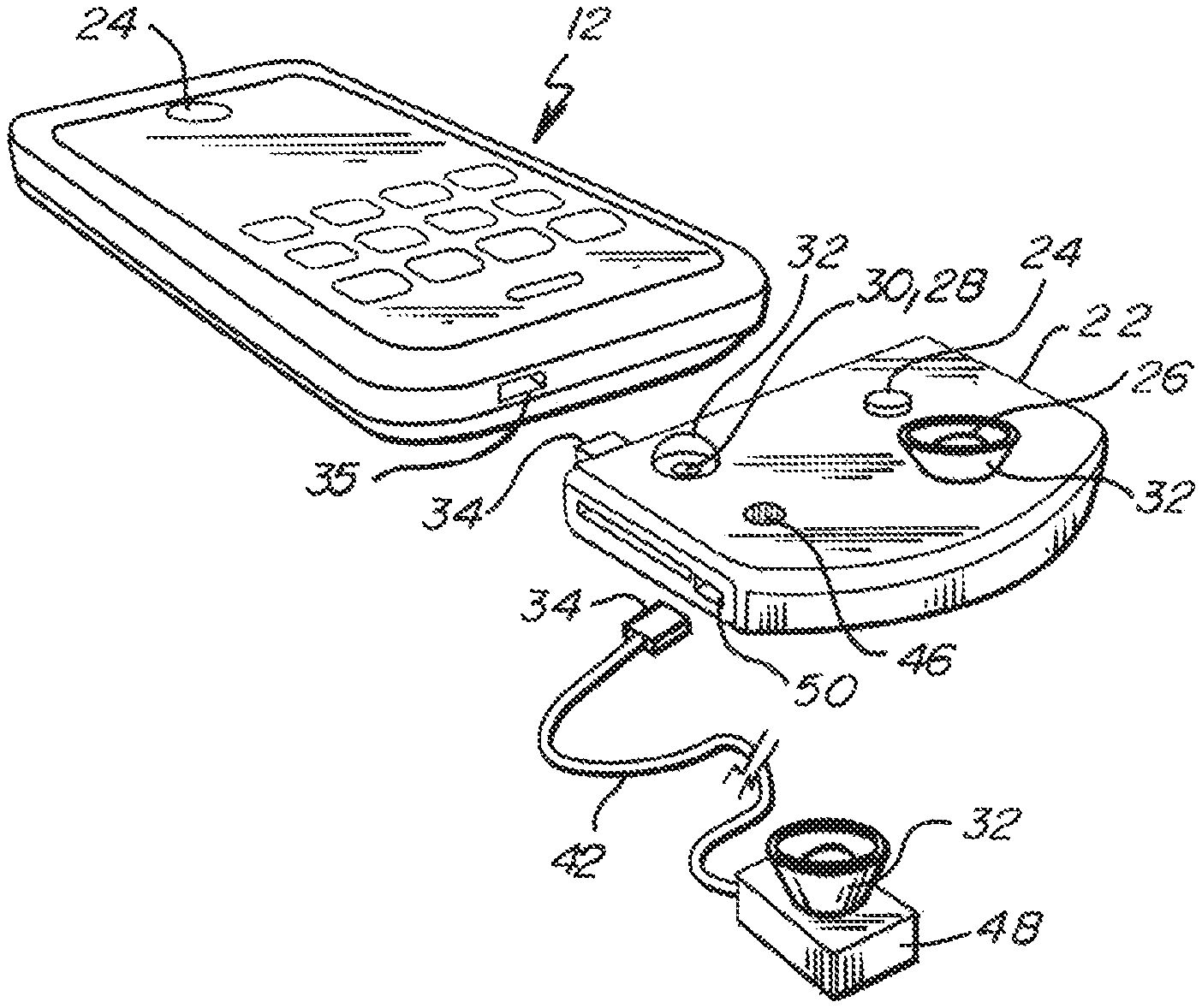
FIG. 4 depicts an isometric view of one alternative embodiment of a supplemental optical transceiver for engagement to a personal electronic device of the invention;
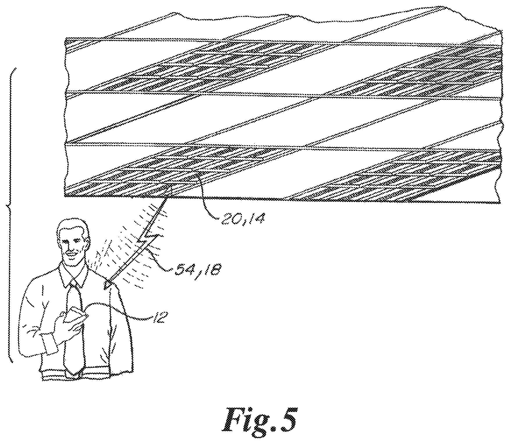
FIG. 5 depicts an environmental view of one alternative embodiment of the use of the invention.
DETAILED DESCRIPTION OF THE PREFERRED EMBODIMENTS
In at least one embodiment, the function disabler device and system is indicated by the numeral 10. In some embodiments the function disabler device and system 10 is used with a personal electronic device 12. In general, the function disabler device and system 10 is used to terminate and/or disable a feature of the personal electronic device 12 when the personal electronic device 12 has been transported into an area or location where security is desired.
In general, the function disabler device and system 10 may be customized to target individual and select functions or features of a personal electronic device 12, which may be software programs stored within, or components of, the personal electronic device 12.
The function disabler device and system 10 also includes the use of an embedded pulsed light communication network/system generally referred to by the numeral 14.
The embedded pulsed light communication network/system 14 will be generally described herein, however, additional detail concerning the features, functions, components, and operation of a pulsed light communication network/system 14 are identified within the following United States Patent Applications and United States Patents which are incorporated by reference herein in their entireties. The United States Patent Applications and United States Patents incorporated by reference herein in their entireties include the following: Ser. Nos. 15/168,939; 15/076,093; 15/042,830; 15/005,305; 15/013,131; 15/042,843; 14/817,411; 14/597,648; 14/597,518; 14/557,705; 14/546,218; 14/537,470; 14/288,917; 14/290,152; 14/270,670; 14/207,934; 12/126,469; 12/126,647; 12/126,342; 12/032,908; 11/433,979; 62/203,697; 61/927,663; 61/927,638; 61/867,731; 61/819,861; 61/778,672; 61/165,546; 61/432,949; 60/931,611; 60/322,166; 60/248,894; Pat. Nos. 9,265,112; 9,258,864; 9,294,198; 9,100,124; 9,246,594; 9,252,883; 9,363,018; 8,886,045; 8,751,390; 8,902,076; 8,593,299; 8,571,411; 8,331,790; 8,744,267; 8,543,505; 8,890,773; 8,188,879; 8,687,965; 8,188,878; 7,046,160; and 6,879,263.
In general, the function disabler device and system 10 begins with the downloading of a pulsed light interface software application generally referred to by reference numeral 16. The pulsed light interface software application 16 is downloaded onto the personal electronic device 12. Conventional downloading techniques including but not limited to the use of the global telecommunications network, a wired internet connection and/or wired or wireless communication with another electronic device, by reading a flash memory device, or by reading of a portable disk or another type of electronic storage media to name a few may be used to store the pulsed light interface software application 16 on the personal electronic device 12.
In general, the personal electronic device 12 may be any communication device including but not limited to telephones, cellular telephones, smart phones, tablets, computers, laptop computers, and/or other electronic devices as used by an individual.
In general, the downloading of the pulsed light interface software application 16 onto the personal electronic device 12 establishes connectivity and communication with the embedded pulsed light communication network/system 14.
In at least one embodiment, the pulsed light interface software application 16 will enable the personal electronic device 12 to communicate, transmit, and/or receive pulsed light communication signals or data 18 as embedded within illumination emitted from a light emitting diode light fixture 20.
In some embodiments, the pulsed light interface software application 16, as downloaded onto the personal electronic device 12, permits an individual to immediately become a customer of embedded pulsed light communication and/or data transfer network services. In some embodiments, the pulsed light interface software application 16 also includes recognition software, which may include voice or sound recognition, facial recognition, fingerprint, retinal, or other biometric recognition for an individual.
In some embodiments the pulsed light interface software application 16 enables a customer to speak to the personal electronic device 12 in order to initiate a transmission/communication across the pulsed LED light communication/data system or network 14, similar to the use of a smart phone, substituting pulsed light communication signals 18 for cellular transmissions or Wi-Fi transmissions.
In some embodiments, the function disabler device and system 10 utilizes a supplemental optical transceiver 22 which may be electrically connected to the personal electronic device 12.
In some embodiments the personal electronic device 12 and/or the supplemental optical transceiver 22 includes a processor which may electrically recognize a pulsed light communication signal 18, another electronic signal, a sound, or a light as converted into an electrical signal, in order to translate and communicate the transmission/communication to an individual. The processor may also encode a responsive communication signal for transmission through the light source, for either the personal electronic device 12 or supplemental optical receiver 22, for transmission of a reply visible light communication signal 18, to establish a two-way duplex communication using visual light or embedded pulsed light communication.
It should be noted that in many embodiments that the visual light or embedded pulsed light communication signals 18 described herein are comprised of a plurality of rapid flashes of light having a frequency which is not observable to the unaided eyes of an individual, where the rapid flashes of light may be organized into data packets and/or communications. The rapid flashes of light occur at a frequency which is not detectable by the human eye. In addition, the wavelength of the visible light is in the visible spectrum which functions as illumination. The wavelength of the visible light is not in the infrared spectrum, which may cause physical damage to the eyes of an individual.
In some embodiments, upon completion of the download of the pulsed light interface software application 16 onto a personal electronic device 12, an individual may immediately begin using pulsed light as a communication or data carrier medium for cellular telephone calls, text messaging, emails, or other types of communication. Embedded pulsed light communication provides augmented communication or data transmission, as an alternative to radio signal waves, Wi-Fi signals, Bluetooth communication signals and/or cellular communication signals as previously used by the identical personal electronic device 12.
In at least one embodiment the personal electronic device 12 will include at least one camera 24 or other photodetector 26 having the capability to detect pulsed light communication signals 18. In some embodiments the personal electronic device 12 will also include a light source 28 having the capability to transmit pulsed light communication signals 18.
In some embodiments, the supplemental optical transceiver 22 may be directly attached to, or in communication with, the personal electronic device 12 to enable pulsed light communications 18. The supplemental optical transceiver 22 may include at least one camera 24 or other photodetector 26, an LED light source 30, and/or an optional focusing element 32, where the photodetector 26 has the capability to detect pulsed light communication signals 18.
In some embodiments, the personal electronic device 12 and/or the supplemental optical transceiver 22 will also include sufficient features and software in order to recognize voice commands, audible signals or sounds, and/or commands communicated by transmission of a signal, including text or symbols.
In some embodiments, a photodetector 26 and/or LED light source 30 may be integral to the supplemental optical transceiver 22 which in turn may be releasably connected to a port 35 of a personal electronic device 12 in a manner similar to a portable credit card slide reader, as inserted into a receiving port 35 of device such as a smart phone.
In some embodiments, a portable supplemental optical transceiver 22 having a photodetector 26 and/or LED light source 30 may additionally include suitable electronic circuitry to convert optical pulsed light signals 18 into electrical signals. The portable supplemental optical transceiver 22 may be an accessory, and used in conjunction with the personal electronic device 12 to communicate, receive, and process embedded pulsed light signals 18.
In some embodiments, the supplemental optical transceiver 22 may include sufficient sensitivity and amplification capabilities, including transmitters, receivers, and LED drivers, to establish and maintain connectivity, communication, and data transmission through an embedded pulsed visible light communication network/system 14.
In some embodiments, a facility administrator, retail provider, school administrator, or property owner to name a few, which will be referred collectively to as a hosting customer 36, may automatically download, or assist in the downloading of a customized hosting customer software application 38 onto a personal electronic device 12 of a visitor, employee, contractor, or other individual who is present within the hosting customer facility or location.
In some embodiments, the customized hosting customer software application 38 on the personal electronic device 12 may automatically limit or restrict the operation of features of the electronic device 12, or smart phone, when the personal electronic device 12 is located within certain designated locations within a facility. One or more functions of the personal electronic device 12 may be disabled by the customized hosting customer software application 38 when the personal electronic device 12 is located within a secure area, a restroom, a research and development laboratory, a bookkeeping location, and/or other locations within a hosting customer facility.
In some embodiments, the customized hosting customer software application 38 is targeted to only disable the operation of certain components or functions of a personal electronic device 12 for a limited duration of time, when the personal electronic device is present within a restricted location.
In some embodiments, the pulsed light communication signals 18 may be formed of one or a plurality of data packets. Each packet or combination of signals may be assigned a character, number, or other information as data within memory which may be integral to a controller which in turn may be integral to a light emitting diode light fixture 20, or a personal electronic device 12, using the pulsed light interface software application 16. Individual packets of grouped embedded pulsed light signals may be combined into a message, word, and/or character for processing and/or translation by the pulsed light interface software application 16 on the personal electronic device 12, or the controller integral to the light emitting diode light fixture 20.
In some embodiments, any number of relay light emitting diode light fixtures 20 may be sequentially positioned between the communication system and the personal electronic device 12. Each pulsed light communication signal 18 may therefore be passed from the first LED light sources 28 of the first light emitting diode light fixture 20, to a second photodetector 26 integral to a second light emitting diode light fixture 20, for successive transmission to additional photodetectors 26 of subsequent light emitting diode light fixtures 20, for transmission to a final light emitting diode light fixture 20 which is proximate to a personal electronic device 12. The pulsed light communication signals 18 may therefore be processed sequentially through successive relay sites to a personal electronic device 12.
In this regard, each origin, intermediate, and final relay site or light emitting diode light fixture 20, as well as each personal electronic device 12, is required to have an individual, device specific, stored identifier which may be formed of one or more combinations of pulsed LED light signals, in order to identify a specific device or light fixture address. The addresses for each and every site, light emitting diode light fixture 20 and/or personal electronic device 12, may be stored within the memory for each respective controller.
In some embodiments, LVXR is the acronym for light visually transmitted repeater. The LVXR device will be used as a light signal repeater similar to that in radio repeater towers. A pulsed light communication signal 18 is received, processed for accuracy, routing, etc., and then rebroadcast/rerouted to the next light emitting diode light fixture 20 until the pulsed light communication signal 18 is proximate to the personal electronic device 12. Visual light will go into the LVXR device as packets, be compared with other identifiers, until there are at least two identical identifiers. If the two identifiers are not identical, then the pulsed light communication signal 18 will be sent out in the next step closer to a destination for proper routing. Each device or fixture will receive packeted data via embedded pulsed visual light form, along with other possible augmented communication mediums, in order to process the data packet and then pass the data packet and information to the next LVXR. This procedure will establish an embedded pulsed light communication system or network 14 from one location to another, for the rebroadcasting of embedded pulsed visual light signals 18 from one visual light transceiver to another, for the purpose of creating an optical data communication link over an appreciable, practical distance with accessibility along either all or part of the distance using visual light transmitting/receiving apparatus such as light emitting diode light fixtures 20.
In some embodiments, data may be sent from one location to another using a Global Positioning System (GPS) information as the data packet addressing information, hence connecting the data packet routing information to a geographic location instead of a cyber location. In some embodiments both a GPS address as well as a cyber address is utilized as identifiers in a data packet.
In some embodiments the incorporation of Global Positioning System (GPS) information into the data packet is similar to technology described in U.S. Pat. No. 4,785,463, the entire contents of which is expressly incorporated herein by reference. GPS positioning uses one or more coordinate systems, such as World Geodetic System 1984 (WGS84), to provide a reference frame, allowing every point on earth to be coded with a unique GPS location.
In some embodiments, a data packet may include GPS location header bits that include the packet's destination address in GPS coordinates. The data packet may further include GPS location trailer bits that include the packet's origin address in GPS coordinates. The data packet may further include the address in GPS coordinates of the optical transceiver that most recently transmitted the packet (the last known transmission address, or LTA), as will be described in more detail below. The data packet further includes the data to be transmitted, and may include any other bits of information determined to be necessary for successful transmission of data, such as error detection bits, as understood by a person of ordinary skill in the art.
Routing data packets from one location to another location can be accomplished using GPS location information which tags data packets having a geographic location instead of a cyber-location. Such an embodiment eliminates the need for any later geographic location translation because a data packet starts with geographic source and destination information. This simplifies locating the destination of the data packet.
In some embodiments, each data packet is assigned a GPS origin/destination address as it passes through the network infrastructure. The data packet is always searching for the next closest GPS address location. Each stationary (or static) optical transceiver, and some dynamic optical transceivers, within a network will be designated with a GPS location number. As a data packet passes through the network, it is routed by the optical transceivers, with their internal processors, to the next physically closer optical transceiver within the network. If another optical transceiver is within receiving range, or is connected with another form of communication medium, that optical transceiver receives the data packet. The optical transceiver's internal processor compares its internal GPS location address (ILA) to the data packet's GPS destination address and the optical transceiver's last known transmission address (LTA) stored within the data packet. If the ILA code is closer to the data packet destination address than the LTA code stored within the data packet, the optical transceiver's processor inserts its ILA code into the data packet as the new LTA code and then repeats transmission of the entire data packet with the updated LTA code.
The network continues this process until the data packet reaches the destination optical transceiver, at which point the data packet is transmitted to the personal electronic device 12.
This means each user of the embedded pulsed light communication network/system 14 may declare one or more static positions and have a dynamic position at any time. The system will track the identifier of the pulsed light interface software application 16 of the personal electronic device 12 as a user passes LVXRs, similar to that of cell phones in relation to their towers. Each user of the embedded pulsed light communication network/system 14 may determine at any point what his/her static address is. A static address may be an office, a home, the living room, or other room. When a user leaves his/her static address to traverse through the infrastructure, he/she then becomes dynamic. If a packet of data is transmitted to his or her static address, it will then be informed as to where his/her dynamic address is by using similar schemes as that of cell phones.
In some embodiments, a hosting customer 36 may program a customized hosting customer software application 38 to be embedded within one or more pulsed light communication signals 18, for downloading onto a personal electronic device 12. The downloading of the hosting customer software application 38 onto the personal electronic device 12 may be automatic. In some embodiments, within a restricted area the hosting customer software 38 will issue an instruction or command signal as embedded within one or more pulsed light communication signals 18, to communicate a feature/function disabling communication 40. A hosting customer 36 will be able to identify the applicable light emitting diode light fixtures 20 within the restricted area through the unique and individual device identifiers associated with fixture.
In some embodiments, the light emitting diode light fixtures 20 within a restricted area will continuously be emitting the feature/function disabling communication 40 as embedded within illumination for receipt by the hosting customer software application 38 on the personal electronic device 12. The receipt by the personal electronic device 12 of the feature/function disabling communication 40 will terminate the operation and/or use of a feature such as a camera, microphone, texting function, or recording function to name a few within the restricted area.
In some embodiments, when a personal electronic device 12 is transported out of a restricted area the pulsed light communication signals 18 as embedded within illumination will not include the feature/function disabling communication 40, whereupon the features/functions such as the camera, microphone, texting messaging function, or recording function will return to an active status for use by an individual.
The component of the personal electronic device 12 being disabled may also be a voice recording function, a video recording function, an audio or visual file transfer, a live cellular phone connection or conversation, and/or an email communication may be prohibited to name a few of the many functions which may be disabled, thereby preventing an unauthorized photograph, recording, or communication.
Many other types of components, functions, or features of an electronic device 12 may be disabled in addition to the components, functions, or features identified herein. In some embodiments, a personal electronic device 12 may therefore not be available for use as a recording or surveillance tool or device by an individual.
It should be noted that the features, functions, or operation of the personal electronic device 12 in some embodiments will only be disabled when the personal electronic device 12 is present within a restricted or secure area within a hosting customer 36 facility.
In some embodiments, the enablement or termination of targeted functionality of a personal electronic device 12 may be established and/or regulated by the feature/function disabling communication 40 as programmed within the customer hosting software application 38.
In some embodiments, the termination, limitation and/or restriction of access to one or more components of a personal electronic device 12 within certain designated or restricted areas of a hosting customer facility may be particularly important in sensitive governmental locations.
In some embodiments, embedded pulsed light communications or signals 18 will continue to be emitted by light emitting diode light fixtures 20 which are located within certain restricted areas or locations of a facility or structure of a hosting customer 36. In some embodiments, the personal electronic device 12 may continue to receive information and/or embedded pulsed light communication signals 18 within the restricted area or location, however, transmission and/or recording of information, and the transmission of any communication or information as embedded pulsed light communication signals 18 may be prohibited within the designated restricted or secure area.
In some embodiments the embedded pulsed light communication or signals 18, as broadcast from an light emitting diode light fixture 20 may also include command signals to be received by the photodetector, detector, or receiver of the personal electronic device 12 and/or supplemental optical transceiver 22, as generated by the customized hosting customer software application 38.
In some embodiments the feature/function disabling communication 40 may be communicated to a personal electronic device 12 through a supplemental optical transceiver assembly 22. In other embodiments, the feature/function disabling communication 40 may be received by the personal electronic device 12 by detection of the embedded pulsed light communication signal 18 by a camera or photodetector which may be integral to the personal electronic device 12.
In some embodiments the feature/function disabling communication 40 as communicated to a personal electronic device 12 will be automatically received when the personal electronic device 12 enters into a restricted or secure area. In some embodiments an individual may not immediately recognize that a function/feature or operation of the personal electronic device 12 has been temporarily disabled or interrupted.
In some embodiments, the connectable supplemental optical transceiver assembly 22 may have any size dimension as desired and in some embodiments may have reduced size dimensions to be similar in size to a postage stamp or credit card swipe reader. In some embodiments, the connectable supplemental optical transceiver 22 may include a connection member 34, for interface and/or insertion into a receiving port 35 of a personal electronic device 12 such as a smart or cellular telephone.
In some embodiments, the connectable supplemental optical transceiver 22 may include equipment and/or devices such as LED's 30, cameras 24, microphones 46, recorders, photodetectors 26 or flashing illumination sources to name a few.
In some embodiments, the supplemental optical transceiver 22 may be used to amplify and/or to be temporarily attached to personal electronic device 12, which would enhance a desired feature or function of the personal electronic device 12. For example, a supplemental optical transceiver 22 may include electrical components to focus and enhance available lighting functions of the personal electronic device 12 to improve performance of a camera 24.
In an alternative embodiment, a focusing element 32 may be used to enhance or amplify receipt of light transmitted from a remote location as detected by the photodetector 26. Alternatively, the supplemental optical transceiver 22 may include a more robust camera 24 capable of capturing images having an enhanced resolution.
In other embodiments, the supplemental optical transceiver 22 may include LED light illumination sources 30 to enhance the flash capabilities of the personal electronic device 12 to improve camera functionality.
In some embodiments, any number of supplemental optical transceivers 22 may be readily interchangeable for use with a personal electronic device 12, where each supplemental optical transceiver 22 provides improved or unique functionality of components or features, dependent upon the requirements of a particular situation or environmental condition.
In alternative embodiments, the supplemental optical transceiver 22 may include one or more software applications in order to permit an individual to easily adjust the operational performance of the components or features of the personal electronic device 12.
In some embodiments an individual may desire to enhance the performance of a personal electronic device 12 to increase the effective signal transmission or reception capabilities. In some embodiments, an individual may employ the use of a supplemental transmission/reception amplification device 48, as an accessory, which is inserted into a receiving port 50 of the supplemental optical transceiver 22 or personal electronic device 12. In some embodiments, the supplemental transmission/reception amplification device 48 will augment the capabilities of the personal electronic device 12.
In some embodiments the supplemental transmission/reception amplification device 48 may establish and interface with a receiving port 50 in order to establish an electrical transfer link between the supplemental transmission/reception amplification device 48 and the supplemental optical transceiver 22 and/or personal electronic device 12. In some embodiments the supplemental transmission/reception amplification device 48 includes an electrical power source or battery.
In some embodiments, the supplemental transmission/reception amplification device 48 may be similar in appearance to, and be the approximate size of, a periscope pencil eraser which includes one or more focusing mirrors which project upwardly instead of horizontally from a personal electric device 12. In alternative embodiments, the supplemental transmission/reception amplification device 48 may include a focusing element or lens 32.
In some embodiments, the supplemental optical transceiver 22 is not restricted to the use of LED lighting elements 30, cameras 24, photodetectors 26, microphones 46, recorders, video recorders, or other devices, and may additionally include an almost infinite variety of devices or functionalities including magnetic strip readers, credit card readers, voice or facial recognition features, retinal scanners or fingerprint scanners to name a few.
In some embodiments, the supplemental optical transceiver 22, or the supplemental transmission/reception device 48 may be attached to a cover or protector, about the back, top or the perimeter of a personal electronic device 12, to provide a streamlined appearance while simultaneously enhancing the functionality and/or flexibility of the personal electronic device 12.
In some embodiments, a bubble reflective surface may be positioned proximate to, or in covering relationship relative to, the LED light source 30 and/or flash diode. The bubble or other reflective device may focus light emitted from the light emitting diodes 30 for use in the embedded pulsed light communication/data transfer network/system 14. In some embodiments the bubble or other reflective device may focus light in an upward direction as opposed to a diffuse transmission direction.
In some embodiments, alternative configurations of supplemental transmission/reception devices 48 may be used to enhance the operational performance capabilities of a personal electronic device 12 to provide a desired communication or transmission speed or rate. For example, transmission of text messages, or surfing the Internet, may require devices having different configurations to provide the desired level of performance.
In some embodiments, the focusing element 32 may be a reflector which may be conical, parabolic, or any other shape as desired by an individual to enhance the reception of signals by a photodetector 26 or to record images by a camera 24. The focusing element 32 will in some embodiments additionally enhance the transmission of light from a light source such as an LED light source 30.
In some embodiments, the focusing element 32 may be affixed to, or integral with, the personal electronic device 12. In other embodiments the focusing element 32 may be directly connected to a personal electronic device 12 by attachment of the focusing element 32 to a personal electronic device 12 proximate to a photodetector 26, LED light source 30, and/or camera 24. In other embodiments, the focusing element 32 may be indirectly connected to the personal electronic device 12, by attachment of the connecting member 34 of the supplemental optical transceiver 22 and/or the supplemental transmission/reception amplification device 48 with the receiving port 35 of the personal electronic device 12.
In other embodiments, the connection member 34 may be engaged to one end of an electrical cord or connector 42 and the focusing element 32, supplemental optical transceiver 22 and/or the supplemental transmission/reception amplification device 48 may be engaged to the opposite end of the electrical cord/connector 42.
In some embodiments, the electrical cord/connector 42 comprises flexible, resilient shaping qualities which in turn may permit the electrical cord/connector 42 to function in a manner similar to a snorkel for manipulation into a desired shape and direction. In some embodiments, the electrical cord/connector 42 may be enclosed within a segmented metal sheath which permits repeated shaping and retention of the electrical cord/connector 42 in a desired configuration/position. It should be noted that many alternative mechanical elements may be used to provide the electrical cord/connector 42 with the resiliently flexible shaping qualities as will be apparent to a person of ordinary skill in the art. In addition, a sheath for the electrical cord/connector 42 is not required to be formed of metal and may be formed of alternative materials, composite materials, and combinations of materials provided that the essential functions, features, and attributes as described herein are not sacrificed.
In some embodiments, the electrical cord/connector 42 may include pivoting or rotational elements on either end or at any desire location there between to permit adjustable rotation of the focusing element 32, supplemental optical transceiver 22, or the supplemental transmission/reception amplification device 48 relative to the connection member 34. In some embodiments, the portion of the electrical cord/connector 42 adjacent to the focusing element 32, supplemental optical transceiver 22, and/or the supplemental transmission/reception amplification device 48 may include an adjustable, rotatable pivoting device or head to permit manipulation of a feature such as a photodetector 26, camera 24, light source 28, LED light source 30, focusing element 32, microphone 46 and/or speaker 44 to be manipulated into any desired direction. In some embodiments the electrical cord/connector 42 may permit an individual to grasp a component, the supplemental optical transceiver 22 and/or the supplemental transmission/reception amplification device 48 in order to point the same in any desired direction.
In some embodiments, the hosting customer software application 38 functions to temporarily interrupt and disable the initiation of a specific execute software command on the personal electronic device 12 for a designated component such as a camera 24, microphone 42, text message, cellular transmission, video recording, or other recording function to name a few.
In other embodiments, the hosting customer software application 38 alternatively or simultaneously may function to temporarily interrupt, terminate, and disable an active specific software command or function on the personal electronic device 12 for a designated component such as a camera 24, microphone 42, text message, cellular transmission, video recording or other recording function to name a few.
In some embodiments, the hosting customer software application 38 initiates a termination/disable command to an active function or component of a personal electronic device 12 overriding the internal personal electronic device 12 component or function internal software.
In some embodiments the hosting customer software application 38 does not override the entire personal electronic device 12 operating system, except to the extent that a capability or function of a prohibited component is temporarily blocked or terminated, preventing execution during the period of time when the personal electronic device 12 is located within a restricted area within a hosting customer facility.
It should be noted that the hosting customer software application 38 may be customized to block or terminate any type of feature or function of a personal electronic device 12 for a designated area. For example, in a restroom the camera 24 and video recording functions may be disabled leaving text messaging or cellular communications in an operational status. In a research and development laboratory video recording, camera 24, microphone 42, cellular telephone, and text messaging functions all may be disabled. Therefore, specific features and/or components of a personal electronic device 12 may be blocked or terminated dependent on the area of the hosting customer facility the personal electronic device 12 is located within.
Referring to FIG. 1, in some embodiments, a personal electronic device 12 may receive a download represented by arrow 52, of a pulsed light interface software application 16 to provide the personal electronic device 12 with pulsed light communication capabilities designated by arrow 54. The pulsed light communication signals 18 are transmitted by the light emitting diode light fixture 20.
Referring to FIG. 2, in some embodiments, supplemental optical transceiver 22 is constructed and arranged for interface and electrical communication with a personal electronic device 12. Supplemental optical transceiver 22 may receive and may transmit pulsed light communication signals 18 as designated by arrow 54 to or from light emitting diode light fixture 20.
In some embodiments, FIG. 1 shows personal electronic device 12 in direct communication with an embedded pulsed light communication system 14 through a light emitting diode light fixture 20. In some embodiments, FIG. 2 shows supplemental optical transceiver 22 interfaced with personal electronic device 12 where supplemental optical transceiver 22 is in communication with an embedded pulsed light communication system 14 through a light emitting diode light fixture 20.
Referring to FIG. 3, in some embodiments, the personal electronic device 12 is in communication for transmission or receipt of pulsed light communication signals 18, represented by arrow 54, to and from hosting customer software application 38 as communicated from light emitting diode light fixture 20. In an alternative embodiment the supplemental optical transceiver 22 is shown in phantom line. In at least one embodiment as depicted in FIG. 3, the transmission of a pulsed light communication signal 18 representative of an impermissible recording, transmission or communication is blocked, as represented by line 56. The blockage of transmission 18 generally occurs within a processor including software as integral with personal electronic device 12 and/or supplemental optical transceiver 22. Alternatively, the disabling of the transmission 18 may occur within a processor including software as integral with supplemental transmission/reception amplification device 48.
Referring to FIG. 4, in one embodiment, a supplemental optical transceiver 22 is shown for engagement with a personal electronic device 12. In addition, in one embodiment as depicted in FIG. 4 the supplemental transmission/reception amplification device 48 may be electrically coupled to the supplemental optical transceiver 22. Alternatively, the supplemental transmission/reception amplification device 48 may be directly connected to personal electronic device 12 by the interface of connection member 34 with receiving port 35.
Referring to FIG. 5, the at least one embodiment an individual holding a personal electronic device is shown communicating with the embedded pulsed light communication network/system 14 through the transmission of pulsed light communication signals 18 to and from an LED light fixture 20.
In a first alternative embodiment, a function disabler system comprises a personal electronic device, the personal electronic device comprising at least one component, the personal electronic device further comprising a processor comprising pulsed light communication software, the pulsed light communication software being constructed and arranged to enable receipt and transmission of pulsed light communication signals, the pulsed light communication signals having a wavelength in the visible spectrum, the processor further comprising hosting customer software, the at least one pulsed light communication signals comprising an instruction signal, the hosting customer software being constructed and arranged to process the instruction signal, where the hosting customer software processes the instruction signal and disables the at least one component when the personal electronic device is positioned in a designated secure area.
In a second alternative embodiment according to the first embodiment, the at least one component is selected from the group consisting of a camera, microphone, speaker, photodetector, light source, LED light source, text message communication device, video recording device, and audio recording device and combinations thereof.
In a third alternative embodiment according to the second embodiment, the function disabler system further comprises a supplemental optical transceiver.
In a fourth alternative embodiment according to the third embodiment, the personal electronic device further comprises a receiving port.
In a fifth alternative embodiment according to the fourth embodiment, the supplemental optical receiver further comprises a connection member.
In a sixth alternative embodiment according to the fifth embodiment, the supplemental optical transceiver comprises a supplemental receiving port.
In a seventh alternative embodiment according to the sixth embodiment, the function disabler system further comprises a supplemental transmission device and the supplemental transmission device comprises a supplemental connection member which is constructed and arranged for engagement to the supplemental receiving port.
In an eighth alternative embodiment according to the third embodiment, the supplemental optical transceiver further comprises a focusing element.
In a ninth alternative embodiment according to the third embodiment, the function disabler system further comprises a supplemental transmission device.
In a tenth alternative embodiment, according to the ninth embodiment, the supplemental transmission device comprises an electrical cord.
In an eleventh alternative embodiment according to the tenth alternative embodiment, the electrical cord is resiliently flexible.
In a twelfth alternative embodiment according to the second alternative embodiment the personal electronic device further comprises a focusing element.
In a thirteenth alternative embodiment according to the twelfth alternative embodiment, the personal electronic device comprises a back, a side, and a top, wherein the supplemental optical transceiver is engaged to one of the back, the side, and the top of the personal electronic device.
In a fourteenth alternative embodiment according to the first alternative embodiment the function disabler system further comprises a supplemental transmission device.
In a fifteenth alternative embodiment according to the fourteenth alternative embodiment the supplemental transmission device comprises an electrical cord.
In a sixteenth alternative embodiment according to the fifteenth alternative embodiment the electrical cord is resiliently flexible.
In a seventeenth alternative embodiment according to the fourteenth alternative embodiment the supplemental transmission device comprises at least one supplemental component, the supplemental component being selected from the group consisting of a camera, microphone, speaker, photodetector, light source, LED light source, text message communication device, video recording device, and audio recording device and combinations thereof.
In an eighteenth alternative embodiment according to the second alternative embodiment the function disabler system further comprises at least one light emitting diode light fixture.
In a nineteenth alternative embodiment according to the eighteenth alternative embodiment the at least one light emitting diode light fixture generates the pulsed light communication signals and the instruction signal.
In a twentieth alternative embodiment according to the nineteenth alternative embodiment the at least one light emitting diode light fixture comprises a light fixture identifier, the light fixture identifier being embedded in the pulsed light communication signals or the instruction signal.
This completes the description of the preferred and alternate embodiments of the invention. Those skilled in the art may recognize other equivalents to the specific embodiment described herein which equivalents are intended to be encompassed by the claims attached hereto.
The above disclosure is intended to be illustrative and not exhaustive. This description will suggest many variations and alternatives to one of ordinary skill in this art. The various elements shown in the individual figures and described above may be combined or modified for combination as desired. All these alternatives and variations are intended to be included within the scope of the claims where the term "comprising" means "including, but not limited to".
These and other embodiments which characterize the invention are pointed out with particularity in the claims annexed hereto and forming a part hereof. However, for further understanding of the invention, its advantages and objectives obtained by its use, reference should be made to the drawings which form a further part hereof and the accompanying descriptive matter, in which there is illustrated and described embodiments of the invention.
* * * * *
D00000
D00001
D00002
XML
uspto.report is an independent third-party trademark research tool that is not affiliated, endorsed, or sponsored by the United States Patent and Trademark Office (USPTO) or any other governmental organization. The information provided by uspto.report is based on publicly available data at the time of writing and is intended for informational purposes only.
While we strive to provide accurate and up-to-date information, we do not guarantee the accuracy, completeness, reliability, or suitability of the information displayed on this site. The use of this site is at your own risk. Any reliance you place on such information is therefore strictly at your own risk.
All official trademark data, including owner information, should be verified by visiting the official USPTO website at www.uspto.gov. This site is not intended to replace professional legal advice and should not be used as a substitute for consulting with a legal professional who is knowledgeable about trademark law.