Techniques for managing software defined networking controller in-band communications in a data center network
Chander , et al. February 23, 2
U.S. patent number 10,931,629 [Application Number 16/236,757] was granted by the patent office on 2021-02-23 for techniques for managing software defined networking controller in-band communications in a data center network. This patent grant is currently assigned to CISCO TECHNOLOGY, INC.. The grantee listed for this patent is Cisco Technology, Inc.. Invention is credited to Vijay Chander, Praveen Jain, Munish Mehta, Yibin Yang.


| United States Patent | 10,931,629 |
| Chander , et al. | February 23, 2021 |
Techniques for managing software defined networking controller in-band communications in a data center network
Abstract
According to one or more embodiments of this disclosure, a network controller in a data center network establishes a translation table for in-band traffic in a data center network, the translation table resolves ambiguous network addresses based on one or more of a virtual network identifier (VNID), a routable tenant address, or a unique loopback address. The network controller device receives packets originating from applications and/or an endpoints operating in a network segment associated with a VNID. The network controller device translates, using the translation table, unique loopback addresses and/or routable tenant addresses associated with the packets into routable tenant addresses and/or unique loopback addresses, respectively.
| Inventors: | Chander; Vijay (San Ramon, CA), Yang; Yibin (San Jose, CA), Jain; Praveen (Cupertino, CA), Mehta; Munish (Fremont, CA) | ||||||||||
|---|---|---|---|---|---|---|---|---|---|---|---|
| Applicant: |
|
||||||||||
| Assignee: | CISCO TECHNOLOGY, INC. (San
Jose, CA) |
||||||||||
| Family ID: | 1000005380221 | ||||||||||
| Appl. No.: | 16/236,757 | ||||||||||
| Filed: | December 31, 2018 |
Prior Publication Data
| Document Identifier | Publication Date | |
|---|---|---|
| US 20190141010 A1 | May 9, 2019 | |
Related U.S. Patent Documents
| Application Number | Filing Date | Patent Number | Issue Date | ||
|---|---|---|---|---|---|
| 15208018 | Jul 12, 2016 | 10171357 | |||
| 62342746 | May 27, 2016 | ||||
| Current U.S. Class: | 1/1 |
| Current CPC Class: | H04L 61/2592 (20130101); H04L 12/4641 (20130101); H04L 45/02 (20130101); H04L 61/2514 (20130101); H04L 61/2521 (20130101) |
| Current International Class: | H04L 29/12 (20060101); H04L 12/46 (20060101); H04L 12/751 (20130101) |
References Cited [Referenced By]
U.S. Patent Documents
| 5742829 | April 1998 | Davis et al. |
| 5903545 | May 1999 | Sabourin et al. |
| 6012096 | January 2000 | Link et al. |
| 6144962 | November 2000 | Weinberg et al. |
| 6247058 | June 2001 | Miller et al. |
| 6330562 | December 2001 | Boden et al. |
| 6525658 | February 2003 | Streetman et al. |
| 6597663 | July 2003 | Rekhter |
| 6611896 | August 2003 | Mason, Jr. et al. |
| 6728779 | April 2004 | Griffin et al. |
| 6801878 | October 2004 | Hintz et al. |
| 6847993 | January 2005 | Novaes et al. |
| 6925490 | August 2005 | Novaes et al. |
| 6958998 | October 2005 | Shorey |
| 6983323 | January 2006 | Cantrell et al. |
| 6996817 | February 2006 | Birum et al. |
| 7002464 | February 2006 | Bruemmer et al. |
| 7096368 | August 2006 | Kouznetsov et al. |
| 7120934 | October 2006 | Ishikawa |
| 7162643 | January 2007 | Sankaran et al. |
| 7181769 | February 2007 | Keanini et al. |
| 7185103 | February 2007 | Jain |
| 7337206 | February 2008 | Wen et al. |
| 7353511 | April 2008 | Ziese |
| 7370092 | May 2008 | Aderton et al. |
| 7395195 | July 2008 | Suenbuel et al. |
| 7444404 | October 2008 | Wetherall et al. |
| 7466681 | December 2008 | Ashwood-Smith et al. |
| 7467205 | December 2008 | Dempster et al. |
| 7496040 | February 2009 | Seo |
| 7496575 | February 2009 | Buccella et al. |
| 7530105 | May 2009 | Gilbert et al. |
| 7610330 | October 2009 | Quinn et al. |
| 7633942 | December 2009 | Bearden et al. |
| 7676570 | March 2010 | Levy et al. |
| 7681131 | March 2010 | Quarterman et al. |
| 7693947 | April 2010 | Judge et al. |
| 7752307 | July 2010 | Takara |
| 7774498 | August 2010 | Kraemer et al. |
| 7783457 | August 2010 | Cunningham |
| 7844696 | November 2010 | Labovitz et al. |
| 7844744 | November 2010 | Abercrombie et al. |
| 7864707 | January 2011 | Dimitropoulos et al. |
| 7873025 | January 2011 | Patel et al. |
| 7874001 | January 2011 | Beck et al. |
| 7885197 | February 2011 | Metzler |
| 7895649 | February 2011 | Brook et al. |
| 7904420 | March 2011 | Ianni |
| 7930752 | April 2011 | Hertzog et al. |
| 7934248 | April 2011 | Yehuda et al. |
| 7957934 | June 2011 | Greifeneder |
| 7961637 | June 2011 | McBeath |
| 7970946 | June 2011 | Djabarov et al. |
| 7975035 | July 2011 | Popescu et al. |
| 8005935 | August 2011 | Pradhan et al. |
| 8040232 | October 2011 | Oh et al. |
| 8040822 | October 2011 | Proulx et al. |
| 8056134 | November 2011 | Ogilvie |
| 8135657 | March 2012 | Kapoor et al. |
| 8156430 | April 2012 | Newman |
| 8181248 | May 2012 | Oh et al. |
| 8185824 | May 2012 | Mitchell et al. |
| 8250657 | August 2012 | Nachenberg et al. |
| 8255972 | August 2012 | Azagury et al. |
| 8266697 | September 2012 | Coffman |
| 8281397 | October 2012 | Vaidyanathan et al. |
| 8291495 | October 2012 | Burns et al. |
| 8296847 | October 2012 | Mendonca et al. |
| 8365286 | January 2013 | Poston |
| 8370407 | February 2013 | Devarajan et al. |
| 8381289 | February 2013 | Pereira et al. |
| 8391270 | March 2013 | Van Der Stok et al. |
| 8407164 | March 2013 | Malik et al. |
| 8413235 | April 2013 | Chen et al. |
| 8442073 | May 2013 | Skubacz et al. |
| 8451731 | May 2013 | Lee et al. |
| 8462212 | June 2013 | Kundu et al. |
| 8489765 | July 2013 | Vasseur et al. |
| 8516590 | August 2013 | Ranadive et al. |
| 8527977 | September 2013 | Cheng et al. |
| 8549635 | October 2013 | Muttik et al. |
| 8570861 | October 2013 | Brandwine et al. |
| 8572600 | October 2013 | Chung et al. |
| 8572734 | October 2013 | McConnell et al. |
| 8572735 | October 2013 | Ghosh et al. |
| 8572739 | October 2013 | Cruz et al. |
| 8588081 | November 2013 | Salam et al. |
| 8600726 | December 2013 | Varshney et al. |
| 8613084 | December 2013 | Dalcher |
| 8630316 | January 2014 | Haba |
| 8631464 | January 2014 | Belakhdar et al. |
| 8640086 | January 2014 | Bonev et al. |
| 8661544 | February 2014 | Yen et al. |
| 8677487 | March 2014 | Balupari et al. |
| 8683389 | March 2014 | Bar-Yam et al. |
| 8706914 | April 2014 | Duchesneau |
| 8713676 | April 2014 | Pandrangi et al. |
| 8719452 | May 2014 | Ding et al. |
| 8719835 | May 2014 | Kanso et al. |
| 8752042 | June 2014 | Ratica |
| 8752179 | June 2014 | Zaitsev |
| 8755396 | June 2014 | Sindhu et al. |
| 8762951 | June 2014 | Kosche et al. |
| 8769084 | July 2014 | Westerfeld et al. |
| 8776180 | July 2014 | Kumar et al. |
| 8812725 | August 2014 | Kulkarni |
| 8813236 | August 2014 | Saha et al. |
| 8825848 | September 2014 | Dotan et al. |
| 8832013 | September 2014 | Adams et al. |
| 8832461 | September 2014 | Saroiu et al. |
| 8849926 | September 2014 | Marzencki et al. |
| 8881258 | November 2014 | Paul et al. |
| 8887238 | November 2014 | Howard et al. |
| 8904520 | December 2014 | Nachenberg et al. |
| 8908685 | December 2014 | Patel et al. |
| 8931043 | January 2015 | Cooper et al. |
| 8954610 | February 2015 | Berke et al. |
| 8955124 | February 2015 | Kim et al. |
| 8966625 | February 2015 | Zuk et al. |
| 8973147 | March 2015 | Pearcy et al. |
| 8984331 | March 2015 | Quinn |
| 8990386 | March 2015 | He et al. |
| 8996695 | March 2015 | Anderson et al. |
| 8997227 | March 2015 | Mhatre et al. |
| 9015716 | April 2015 | Fletcher et al. |
| 9071575 | June 2015 | Lemaster et al. |
| 9088598 | July 2015 | Zhang et al. |
| 9110905 | August 2015 | Polley et al. |
| 9117075 | August 2015 | Yeh |
| 9152789 | October 2015 | Natarajan et al. |
| 9160764 | October 2015 | Stiansen et al. |
| 9178906 | November 2015 | Chen et al. |
| 9185127 | November 2015 | Neou et al. |
| 9191402 | November 2015 | Yan |
| 9197654 | November 2015 | Ben-Shalom et al. |
| 9225793 | December 2015 | Dutta et al. |
| 9237111 | January 2016 | Banavalikar et al. |
| 9246773 | January 2016 | Degioanni |
| 9258217 | February 2016 | Duffield et al. |
| 9281940 | March 2016 | Matsuda et al. |
| 9294486 | March 2016 | Chiang et al. |
| 9317574 | April 2016 | Brisebois et al. |
| 9319384 | April 2016 | Yan et al. |
| 9369479 | June 2016 | Lin |
| 9396327 | June 2016 | Shimomura et al. |
| 9405903 | August 2016 | Xie et al. |
| 9418222 | August 2016 | Rivera et al. |
| 9426068 | August 2016 | Dunbar et al. |
| 9454324 | September 2016 | Madhavapeddi |
| 9501744 | November 2016 | Brisebois et al. |
| 9634915 | April 2017 | Bley |
| 9645892 | May 2017 | Patwardhan |
| 9733973 | August 2017 | Prasad et al. |
| 2002/0053033 | May 2002 | Cooper et al. |
| 2002/0103793 | August 2002 | Koller et al. |
| 2002/0141343 | October 2002 | Bays |
| 2002/0184393 | December 2002 | Leddy et al. |
| 2003/0097439 | May 2003 | Strayer et al. |
| 2003/0145232 | July 2003 | Poletto et al. |
| 2003/0154399 | August 2003 | Zuk et al. |
| 2004/0030776 | February 2004 | Cantrell et al. |
| 2004/0243533 | December 2004 | Dempster et al. |
| 2004/0268149 | December 2004 | Aaron |
| 2005/0039104 | February 2005 | Shah et al. |
| 2005/0063377 | March 2005 | Bryant et al. |
| 2005/0166066 | July 2005 | Ahuja et al. |
| 2005/0185621 | August 2005 | Sivakumar et al. |
| 2005/0207376 | September 2005 | Ashwood-Smith et al. |
| 2005/0257244 | November 2005 | Joly et al. |
| 2005/0289244 | December 2005 | Sahu et al. |
| 2006/0048218 | March 2006 | Lingafelt et al. |
| 2006/0080733 | April 2006 | Khosmood et al. |
| 2006/0095968 | May 2006 | Portolani et al. |
| 2006/0156408 | July 2006 | Himberger et al. |
| 2006/0195448 | August 2006 | Newport |
| 2006/0272018 | November 2006 | Fouant |
| 2006/0274659 | December 2006 | Ouderkirk |
| 2006/0294219 | December 2006 | Ogawa et al. |
| 2007/0044147 | February 2007 | Choi et al. |
| 2007/0097976 | May 2007 | Wood et al. |
| 2007/0169179 | July 2007 | Narad |
| 2007/0195729 | August 2007 | Li et al. |
| 2007/0195797 | August 2007 | Patel et al. |
| 2007/0211637 | September 2007 | Mitchell |
| 2007/0300061 | December 2007 | Kim et al. |
| 2008/0022385 | January 2008 | Crowell et al. |
| 2008/0056124 | March 2008 | Nanda et al. |
| 2008/0082662 | April 2008 | Danliker et al. |
| 2008/0101234 | May 2008 | Nakil et al. |
| 2008/0126534 | May 2008 | Mueller et al. |
| 2008/0250122 | October 2008 | Zsigmond et al. |
| 2008/0270199 | October 2008 | Chess et al. |
| 2008/0301765 | December 2008 | Nicol et al. |
| 2009/0064332 | March 2009 | Porras et al. |
| 2009/0133126 | May 2009 | Jang et al. |
| 2009/0241170 | September 2009 | Kumar et al. |
| 2009/0307753 | December 2009 | Dupont et al. |
| 2009/0313373 | December 2009 | Hanna et al. |
| 2009/0313698 | December 2009 | Wahl |
| 2009/0323543 | December 2009 | Shimakura |
| 2009/0328219 | December 2009 | Narayanaswamy |
| 2010/0005288 | January 2010 | Rao et al. |
| 2010/0077445 | March 2010 | Schneider et al. |
| 2010/0095293 | April 2010 | O'Neill et al. |
| 2010/0095367 | April 2010 | Narayanaswamy |
| 2010/0138810 | June 2010 | Komatsu et al. |
| 2010/0148940 | June 2010 | Gelvin et al. |
| 2010/0153316 | June 2010 | Duffield et al. |
| 2010/0153696 | June 2010 | Beachem et al. |
| 2010/0220584 | September 2010 | DeHaan et al. |
| 2010/0235514 | September 2010 | Beachem |
| 2010/0235915 | September 2010 | Memon et al. |
| 2010/0303240 | December 2010 | Beachem |
| 2010/0319060 | December 2010 | Aiken et al. |
| 2011/0010585 | January 2011 | Bugenhagen et al. |
| 2011/0055381 | March 2011 | Narasimhan et al. |
| 2011/0055388 | March 2011 | Yumerefendi et al. |
| 2011/0066719 | March 2011 | Miryanov et al. |
| 2011/0069685 | March 2011 | Tofighbakhsh |
| 2011/0083125 | April 2011 | Komatsu et al. |
| 2011/0126136 | May 2011 | Abella et al. |
| 2011/0126275 | May 2011 | Anderson et al. |
| 2011/0145885 | June 2011 | Rivers et al. |
| 2011/0170860 | July 2011 | Smith et al. |
| 2011/0173490 | July 2011 | Narayanaswamy et al. |
| 2011/0185423 | July 2011 | Sallam |
| 2011/0196957 | August 2011 | Ayachitula et al. |
| 2011/0202655 | August 2011 | Sharma et al. |
| 2011/0225207 | September 2011 | Subramanian et al. |
| 2011/0228696 | September 2011 | Agarwal et al. |
| 2011/0277034 | November 2011 | Hanson |
| 2011/0302652 | December 2011 | Westerfeld |
| 2011/0314148 | December 2011 | Petersen et al. |
| 2012/0005542 | January 2012 | Petersen et al. |
| 2012/0079592 | March 2012 | Pandrangi |
| 2012/0102361 | April 2012 | Sass et al. |
| 2012/0102543 | April 2012 | Kohli et al. |
| 2012/0117226 | May 2012 | Tanaka et al. |
| 2012/0136996 | May 2012 | Seo et al. |
| 2012/0137278 | May 2012 | Draper et al. |
| 2012/0137361 | May 2012 | Yi et al. |
| 2012/0140626 | June 2012 | Anand et al. |
| 2012/0197856 | August 2012 | Banka et al. |
| 2012/0198541 | August 2012 | Reeves |
| 2012/0216271 | August 2012 | Cooper et al. |
| 2012/0233473 | September 2012 | Vasseur et al. |
| 2012/0240232 | September 2012 | Azuma |
| 2012/0246303 | September 2012 | Petersen et al. |
| 2012/0278021 | November 2012 | Lin et al. |
| 2013/0003538 | January 2013 | Greenburg et al. |
| 2013/0006935 | January 2013 | Grisby |
| 2013/0038358 | February 2013 | Cook et al. |
| 2013/0086272 | April 2013 | Chen et al. |
| 2013/0103827 | April 2013 | Dunlap et al. |
| 2013/0145099 | June 2013 | Liu et al. |
| 2013/0159999 | June 2013 | Chiueh et al. |
| 2013/0174256 | July 2013 | Powers |
| 2013/0179487 | July 2013 | Lubetzky et al. |
| 2013/0179879 | July 2013 | Zhang et al. |
| 2013/0198839 | August 2013 | Wei et al. |
| 2013/0246925 | September 2013 | Ahuja et al. |
| 2013/0247201 | September 2013 | Alperovitch et al. |
| 2013/0254879 | September 2013 | Chesla et al. |
| 2013/0268994 | October 2013 | Cooper et al. |
| 2013/0275579 | October 2013 | Hernandez et al. |
| 2013/0283374 | October 2013 | Zisapel et al. |
| 2013/0290521 | October 2013 | Labovitz |
| 2013/0297771 | November 2013 | Osterloh et al. |
| 2013/0304900 | November 2013 | Trabelsi et al. |
| 2013/0305369 | November 2013 | Karta et al. |
| 2013/0318357 | November 2013 | Abraham et al. |
| 2013/0326623 | December 2013 | Kruglick |
| 2013/0333029 | December 2013 | Chesla et al. |
| 2013/0347103 | December 2013 | Veteikis et al. |
| 2014/0006610 | January 2014 | Formby et al. |
| 2014/0006871 | January 2014 | Lakshmanan et al. |
| 2014/0012814 | January 2014 | Bercovici et al. |
| 2014/0033193 | January 2014 | Palaniappan |
| 2014/0047185 | February 2014 | Peterson et al. |
| 2014/0047372 | February 2014 | Gnezdov et al. |
| 2014/0059200 | February 2014 | Nguyen et al. |
| 2014/0089494 | March 2014 | Dasari et al. |
| 2014/0096058 | April 2014 | Molesky et al. |
| 2014/0115219 | April 2014 | Ajanovic et al. |
| 2014/0143825 | May 2014 | Behrendt et al. |
| 2014/0149490 | May 2014 | Luxenberg et al. |
| 2014/0156814 | June 2014 | Barabash et al. |
| 2014/0164607 | June 2014 | Bai et al. |
| 2014/0165207 | June 2014 | Engel et al. |
| 2014/0173623 | June 2014 | Chang et al. |
| 2014/0192639 | July 2014 | Smirnov |
| 2014/0201717 | July 2014 | Mascaro et al. |
| 2014/0215573 | July 2014 | Cepuran |
| 2014/0215621 | July 2014 | Xaypanya et al. |
| 2014/0281030 | September 2014 | Cui et al. |
| 2014/0289854 | September 2014 | Mahvi |
| 2014/0298461 | October 2014 | Hohndel et al. |
| 2014/0317737 | October 2014 | Shin et al. |
| 2014/0331276 | November 2014 | Frascadore et al. |
| 2014/0331280 | November 2014 | Porras et al. |
| 2014/0331304 | November 2014 | Wong |
| 2014/0351203 | November 2014 | Kunnatur et al. |
| 2014/0351415 | November 2014 | Harrigan et al. |
| 2014/0359695 | December 2014 | Chari et al. |
| 2014/0373146 | December 2014 | Murthy |
| 2015/0009840 | January 2015 | Pruthi et al. |
| 2015/0026809 | January 2015 | Altman et al. |
| 2015/0033305 | January 2015 | Shear et al. |
| 2015/0036533 | February 2015 | Sodhi et al. |
| 2015/0039751 | February 2015 | Harrigan et al. |
| 2015/0046882 | February 2015 | Menyhart et al. |
| 2015/0058976 | February 2015 | Carney et al. |
| 2015/0067143 | March 2015 | Babakhan et al. |
| 2015/0082151 | March 2015 | Liang et al. |
| 2015/0082430 | March 2015 | Sridhara et al. |
| 2015/0085665 | March 2015 | Kompella et al. |
| 2015/0095332 | April 2015 | Beisiegel et al. |
| 2015/0112933 | April 2015 | Satapathy |
| 2015/0113133 | April 2015 | Srinivas et al. |
| 2015/0124608 | May 2015 | Agarwal et al. |
| 2015/0124821 | May 2015 | Chu |
| 2015/0128133 | May 2015 | Pohlmann |
| 2015/0138993 | May 2015 | Forster et al. |
| 2015/0142962 | May 2015 | Srinivas et al. |
| 2015/0195291 | July 2015 | Zuk et al. |
| 2015/0249622 | September 2015 | Phillips et al. |
| 2015/0256555 | September 2015 | Choi et al. |
| 2015/0261842 | September 2015 | Huang et al. |
| 2015/0261886 | September 2015 | Wu et al. |
| 2015/0271255 | September 2015 | Mackay et al. |
| 2015/0295945 | October 2015 | Canzanese, Jr. et al. |
| 2015/0356297 | October 2015 | Yang Ming et al. |
| 2015/0347554 | December 2015 | Vasantham et al. |
| 2015/0358352 | December 2015 | Chasin et al. |
| 2016/0006753 | January 2016 | McDaid et al. |
| 2016/0021131 | January 2016 | Heilig |
| 2016/0026552 | January 2016 | Holden et al. |
| 2016/0036837 | February 2016 | Jain et al. |
| 2016/0050132 | February 2016 | Zhang et al. |
| 2016/0072815 | March 2016 | Rieke et al. |
| 2016/0094529 | March 2016 | Mityagin |
| 2016/0103692 | April 2016 | Guntaka et al. |
| 2016/0105350 | April 2016 | Greifeneder et al. |
| 2016/0112270 | April 2016 | Danait et al. |
| 2016/0117185 | April 2016 | Fang |
| 2016/0119219 | April 2016 | Fang |
| 2016/0119234 | April 2016 | Valencia Lopez et al. |
| 2016/0127395 | May 2016 | Underwood et al. |
| 2016/0147585 | May 2016 | Konig et al. |
| 2016/0162308 | June 2016 | Chen et al. |
| 2016/0162312 | June 2016 | Doherty et al. |
| 2016/0173446 | June 2016 | Nantel |
| 2016/0191476 | June 2016 | Schutz Harald et al. |
| 2016/0205002 | July 2016 | Rieke et al. |
| 2016/0216994 | July 2016 | Sefidcon et al. |
| 2016/0294691 | October 2016 | Joshi |
| 2016/0308908 | October 2016 | Kirby et al. |
| 2016/0357424 | December 2016 | Pang et al. |
| 2016/0357546 | December 2016 | Chang et al. |
| 2016/0357587 | December 2016 | Yadav et al. |
| 2016/0357957 | December 2016 | Deen et al. |
| 2016/0359592 | December 2016 | Kulshreshtha et al. |
| 2016/0359628 | December 2016 | Singh et al. |
| 2016/0359658 | December 2016 | Yadav et al. |
| 2016/0359673 | December 2016 | Gupta et al. |
| 2016/0359677 | December 2016 | Kulshreshtha et al. |
| 2016/0359678 | December 2016 | Madani et al. |
| 2016/0359679 | December 2016 | Parasdehgheibi et al. |
| 2016/0359680 | December 2016 | Parasdehgheibi et al. |
| 2016/0359686 | December 2016 | Parasdehgheibi et al. |
| 2016/0359696 | December 2016 | Yadav et al. |
| 2016/0359697 | December 2016 | Scheib et al. |
| 2016/0359698 | December 2016 | Deen et al. |
| 2016/0359699 | December 2016 | Gandham et al. |
| 2016/0359700 | December 2016 | Pang et al. |
| 2016/0359701 | December 2016 | Pang et al. |
| 2016/0359703 | December 2016 | Gandham et al. |
| 2016/0359704 | December 2016 | Gandham et al. |
| 2016/0359705 | December 2016 | Parasdehgheibi et al. |
| 2016/0359708 | December 2016 | Gandham et al. |
| 2016/0359709 | December 2016 | Deen et al. |
| 2016/0359711 | December 2016 | Deen et al. |
| 2016/0359712 | December 2016 | Alizadeh Attar et al. |
| 2016/0359740 | December 2016 | Parasdehgheibi et al. |
| 2016/0359759 | December 2016 | Singh et al. |
| 2016/0359872 | December 2016 | Yadav et al. |
| 2016/0359877 | December 2016 | Kulshreshtha et al. |
| 2016/0359878 | December 2016 | Prasad et al. |
| 2016/0359879 | December 2016 | Deen et al. |
| 2016/0359880 | December 2016 | Pang et al. |
| 2016/0359881 | December 2016 | Yadav et al. |
| 2016/0359888 | December 2016 | Gupta et al. |
| 2016/0359889 | December 2016 | Yadav et al. |
| 2016/0359890 | December 2016 | Deen et al. |
| 2016/0359891 | December 2016 | Pang et al. |
| 2016/0359897 | December 2016 | Yadav et al. |
| 2016/0359912 | December 2016 | Gupta et al. |
| 2016/0359913 | December 2016 | Gupta et al. |
| 2016/0359914 | December 2016 | Deen et al. |
| 2016/0359915 | December 2016 | Gupta et al. |
| 2016/0359917 | December 2016 | Rao et al. |
| 2016/0373481 | December 2016 | Sultan et al. |
| 2017/0034018 | February 2017 | Parasdehgheibi et al. |
| 2017/0237650 | August 2017 | Beeram |
| 2017/0317974 | November 2017 | Masurekar |
| 2018/0006911 | January 2018 | Dickey |
| 2018/0367409 | December 2018 | Zhang |
| 101093452 | Dec 2007 | CN | |||
| 101770551 | Jul 2010 | CN | |||
| 102521537 | Jun 2012 | CN | |||
| 103023970 | Apr 2013 | CN | |||
| 103716137 | Apr 2014 | CN | |||
| 104065518 | Sep 2014 | CN | |||
| 0811942 | Dec 1997 | EP | |||
| 1383261 | Jan 2004 | EP | |||
| 1450511 | Aug 2004 | EP | |||
| 2045974 | Apr 2008 | EP | |||
| 2887595 | Jun 2015 | EP | |||
| 2009-016906 | Jan 2009 | JP | |||
| 1394338 | May 2014 | KR | |||
| WO 2007/014314 | Feb 2007 | WO | |||
| WO 2007/070711 | Jun 2007 | WO | |||
| WO 2008/069439 | Jun 2008 | WO | |||
| WO 2013/030830 | Mar 2013 | WO | |||
| WO 2015/042171 | Mar 2015 | WO | |||
| WO 2015/099778 | Jul 2015 | WO | |||
| WO 2016/004075 | Jan 2016 | WO | |||
| WO 2016/019523 | Feb 2016 | WO | |||
Other References
|
Arista Networks, Inc., "Application Visibility and Network Telemtry using Splunk," Arista White Paper, Nov. 2013, 11 pages. cited by applicant . Australian Government Department of Defence, Intelligence and Security, "Top 4 Strategies to Mitigate Targeted Cyber Intrusions," Cyber Security Operations Centre Jul. 2013, http://www.asd.gov.au/infosec/top-mitigations/top-4-strategies-explained.- htm. cited by applicant . Author Unknown, "Blacklists & Dynamic Reputation: Understanding Why the Evolving Threat Eludes Blacklists," www.dambala.com 9 pages, Dambala, Atlanta, GA, USA. cited by applicant . Aydin, Galip, et al., "Architecture and Implementation of a Scalable Sensor Data Storage and Analysis Using Cloud Computing and Big Data Technologies," Journal of Sensors, vol. 2015, Article ID 834217, Feb. 2015, 11 pages. cited by applicant . Backes, Michael, et al., "Data Lineage in Malicious Environments," IEEE 2015, pp. 1-13. cited by applicant . Bauch, Petr, "Reader's Report of Master's Thesis, Analysis and Testing of Distributed NoSQL Datastore Riak," May 28, 2015, Brno. 2 pages. cited by applicant . Bayati, Mohsen, et al., "Message-Passing Algorithms for Sparse Network Alignment," Mar. 2013, 31 pages. cited by applicant . Berezinski, Przemyslaw, et al., "An Entropy-Based Network Anomaly Detection Method," Entropy, 2015, vol. 17, www.mdpi.com/joumal/entropy, pp. 2367-2408. cited by applicant . Berthier, Robin, et al. "Nfsight: Netflow-based Network Awareness Tool," 2010, 16 pages. cited by applicant . Bhuyan, Dhiraj, "Fighting Bots and Botnets," 2006, pp. 23-28. cited by applicant . Blair, Dana, et al., U.S. Appl. No. 62/106,006, filed Jan. 21, 2015, entitled "Monitoring Network Policy Compliance." cited by applicant . Bosch, Greg, "Virtualization," 2010, 33 pages. cited by applicant . Breen, Christopher, "MAC 911, How to dismiss Mac App Store Notifications," Macworld.com, Mar. 24, 2014, 3 pages. cited by applicant . Chandran, Midhun, et al., "Monitoring in a Virtualized Environment," GSTF International Journal on Computing, vol. 1, No. 1, Aug. 2010. cited by applicant . Chari, Suresh, et al., "Ensuring continuous compliance through reconciling policy with usage," Proceedings of the 18.sup.th ACM symposium on Access control models and technologies (SACMAT '13). ACM, New York, NY, USA, 49-60. cited by applicant . Chen, Xu, et al., "Automating network application dependency discovery: experiences, limitations, and new solutions," 8th USENIX conference on Operating systems design and implementation (OSDI'08), USENIX Association, Berkeley, CA, USA, 117-130. cited by applicant . Chou, C.W., et al., "Optical Clocks and Relativity," Science vol. 329, Sep. 24, 2010, pp. 1630-1633. cited by applicant . Cisco Systems, "Cisco Network Analysis Modules (NAM) Tutorial," Cisco Systems, Inc., Version 3.5. cited by applicant . Cisco Systems, Inc., "Addressing Compliance from One Infrastructure: Cisco Unified Compliance Solution Framework," 2014. cited by applicant . Cisco Systems, Inc., "Cisco Application Dependency Mapping Service," 2009. cited by applicant . Cisco Systems, Inc., "White Paper--New Cisco Technologies Help Customers Achieve Regulatory Compliance," 1992-2008. cited by applicant . Cisco Systems, Inc., "A Cisco Guide to Defending Against Distributed Denial of Service Attacks," May 3, 2016, 34 pages. cited by applicant . Cisco Systems, Inc., "Cisco Application Visibility and Control," Oct. 2011, 2 pages. cited by applicant . Cisco Systems, Inc., "Cisco Tetration Platform Data Sheet", Updated Mar. 5, 2018, 21 pages. cited by applicant . Cisco Technology, Inc., "Cisco Lock-and-Key:Dynamic Access Lists," http://www/cisco.com/c/en/us/support/docs/security-vpn/lock-key/7604-13.h- tml; Updated Jul. 12, 2006, 16 pages. cited by applicant . Di Lorenzo, Guisy, et al., "EXSED: An Intelligent Tool for Exploration of Social Events Dynamics from Augmented Trajectories," Mobile Data Management (MDM), pp. 323-330, Jun. 3-6, 2013. cited by applicant . Duan, Yiheng, et al., Detective: Automatically Identify and Analyze Malware Processes in Forensic Scenarios via DLLs, IEEE ICC 2015--Next Generation Networking Symposium, pp. 5691-5696. cited by applicant . Feinstein, Laura, et al., "Statistical Approaches to DDoS Attack Detection and Response," Proceedings of the DARPA Information Survivability Conference and Exposition (DISCEX '03), Apr. 2003, 12 pages. cited by applicant . George, Ashley, et al., "NetPal: A Dynamic Network Administration Knowledge Base," 2008, pp. 1-14. cited by applicant . Goldsteen, Abigail, et al., "A Tool for Monitoring and Maintaining System Trustworthiness at Run Time," REFSQ (2015), pp. 142-147. cited by applicant . Hamadi, S., et al., "Fast Path Acceleration for Open vSwitch in Overlay Networks," Global Information Infrastructure and Networking Symposium (GIIS), Montreal, QC, pp. 1-5, Sep. 15-19, 2014. cited by applicant . Heckman, Sarah, et al., "On Establishing a Benchmark for Evaluating Static Analysis Alert Prioritization and Classification Techniques," IEEE, 2008; 10 pages. cited by applicant . Hewlett-Packard, "Effective use of reputation intelligence in a security operations center," Jul. 2013, 6 pages. cited by applicant . Hideshima, Yusuke, et al., "STARMINE: A Visualization System for Cyber Attacks," https://www.researchgate.net/publication/221536306, Feb. 2006, 9 pages. cited by applicant . Huang, Hing-Jie, et al., "Clock Skew Based Node Identification in Wireless Sensor Networks," IEEE, 2008, 5 pages. cited by applicant . InternetPerils, Inc., "Control Your Internet Business Risk," 2003-2015, https://www.internetperils.com. cited by applicant . Ives, Herbert, E., et al., "An Experimental Study of the Rate of a Moving Atomic Clock," Journal of the Optical Society of America, vol. 28, No. 7, Jul. 1938, pp. 215-226. cited by applicant . Janoff, Christian, et al., "Cisco Compliance Solution for HIPAA Security Rule Design and Implementation Guide," Cisco Systems, Inc., Updated Nov. 14, 2015, part 1 of 2, 350 pages. cited by applicant . Janoff, Christian, et al., "Cisco Compliance Solution for HIPAA Security Rule Design and Implementation Guide," Cisco Systems, Inc., Updated Nov. 14, 2015, part 2 of 2, 588 pages. cited by applicant . Kerrison, Adam, et al., "Four Steps to Faster, Better Application Dependency Mapping--Laying the Foundation for Effective Business Service Models," BMCSoftware, 2011. cited by applicant . Kim, Myung-Sup, et al. "A Flow-based Method for Abnormal Network Traffic Detection, " IEEE, 2004, pp. 599-612. cited by applicant . Kraemer, Brian, "Get to know your data center with CMDB," TechTarget, Apr. 5, 2006, http://searchdatacenter.techtarget.com/news/118820/Get-to-know-y- our-data-center-with-CMDB. cited by applicant . Lab SKU, "VMware Hands-on Labs--HOL-SDC-1301" Version: 20140321-160709, 2013; http://docs.hol.vmware.com/HOL-2013/holsdc-1301_html_en/ (part 1 of 2). cited by applicant . Lab SKU, "VMware Hands-on Labs--HOL-SDC-1301" Version: 20140321-160709, 2013; http://docs.hol.vmware.com/HOL-2013/holsdc-1301_html_en/ (part 2 of 2). cited by applicant . Lachance, Michael, "Dirty Little Secrets of Application Dependency Mapping," Dec. 26, 2007. cited by applicant . Landman, Yoav, et al., "Dependency Analyzer," Feb. 14, 2008, http://jfrog.com/confluence/display/DA/Home. cited by applicant . Lee, Sihyung, "Reducing Complexity of Large-Scale Network Configuration Management," Ph.D. Dissertation, Carniege Mellon University, 2010. cited by applicant . Li, Ang, et al., "Fast Anomaly Detection for Large Data Centers," Global Telecommunications Conference (GLOBECOM 2010, Dec. 2010, 6 pages. cited by applicant . Li, Bingbong, et al, "A Supervised Machine Learning Approach to Classify Host Roles on Line Using sFlow," in Proceedings of the first edition workshop on High performance and programmable networking, 2013, ACM, New York, NY, USA, 53-60. cited by applicant . Liu, Ting, et al., "Impala: A Middleware System for Managing Autonomic, Parallel Sensor Systems," In Proceedings of the Ninth ACM SIGPLAN Symposium on Principles and Practice of Parallel Programming(PPoPP '03), ACM, New York, NY, USA, Jun. 11-13, 2003, pp. 107-118. cited by applicant . Lu, Zhonghai, et al., "Cluster-based Simulated Annealing for Mapping Cores onto 2D Mesh Networks on Chip," Design and Diagnostics of Electronic Circuits and Systems, pp. 1, 6, 16-18, Apr. 2008. cited by applicant . Matteson, Ryan, "Depmap: Dependency Mapping of Applications Using Operating System Events: a Thesis," Master's Thesis, California Polytechnic State University, Dec. 2010. cited by applicant . Natarajan, Arun, et al., "NSDMiner: Automated Discovery of Network Service Dependencies," Institute of Electrical and Electronics Engineers INFOCOM, Feb. 2012, 9 pages. cited by applicant . Navaz, A.S. Syed, et al., "Entropy based Anomaly Detection System to Prevent DDoS Attacks in Cloud," International Journal of computer Applications (0975-8887), vol. 62, No. 15, Jan. 2013, pp. 42-47. cited by applicant . Neverfail, "Neverfail IT Continuity Architect," 2015, https://web.archive.org/web/20150908090456/http://www.neverfailgroup.com/- products/it-continuity-architect. cited by applicant . Nilsson, Dennis K., et al., "Key Management and Secure Software Updates in Wireless Process Control Environments," In Proceedings of the First ACM Conference on Wireless Network Security (WiSec '08), ACM, New York, NY, USA, Mar. 31-Apr. 2, 2008, pp. 100-108. cited by applicant . Nunnally, Troy, et al., "P3D: A Parallel 3D Coordinate Visualization for Advanced Network Scans," IEEE 2013, Jun. 9-13, 2013, 6 pages. cited by applicant . O'Donnell, Glenn, et al., "The CMDB Imperative: How to Realize the Dream and Avoid the Nightmares," Prentice Hall, Feb. 19, 2009. cited by applicant . Ohta, Kohei, et al., "Detection, Defense, and Tracking of Internet-Wide Illegal Access in a Distributed Manner," 2000, pp. 1-16. cited by applicant . Pathway Systems International Inc., "How Blueprints does Integration," Apr. 15, 2014, 9 pages, http://pathwaysystems.com/company-blog/. cited by applicant . Pathway Systems International Inc., "What is Blueprints?" 2010-2016, http://pathwaysystems.com/blueprints-about/. cited by applicant . Popa, Lucian, et al., "Macroscope: End-Point Approach to Networked Application Dependency Discovery," CoNEXT'09, Dec. 1-4, 2009, Rome, Italy, 12 pages. cited by applicant . Prasad, K. Munivara, et al., "An Efficient Detection of Flooding Attacks to Internet Threat Monitors (ITM) using Entropy Variations under Low Traffic," Computing Communication & Networking Technologies (ICCCNT '12), Jul. 26-28, 2012, 11 pages. cited by applicant . Sachan, Mrinmaya, et al., "Solving Electrical Networks to incorporate Supervision in Random Walks," May 13-17, 2013, pp. 109-110. cited by applicant . Sammarco, Matteo, et al., "Trace Selection for Improved WLAN Monitoring," Aug. 16, 2013, pp. 9-14. cited by applicant . Shneiderman, Ben, et al., "Network Visualization by Semantic Substrates," Visualization and Computer Graphics, vol. 12, No. 5, pp. 733,740, Sep.-Oct. 2006. cited by applicant . Thomas, R., "Bogon Dotted Decimal List," Version 7.0, Team Cymru NOC, Apr. 27, 2012, 5 pages. cited by applicant . Wang, Ru, et al., "Learning directed acyclic graphs via bootstarp aggregating," 2014, 47 pages, http://arxiv.org/abs/1406.2098. cited by applicant . Wang, Yongjun, et al., "A Network Gene-Based Framework for Detecting Advanced Persistent Threats," Nov. 2014, 7 pages. cited by applicant . Witze, Alexandra, "Special relativity aces time trial, `Time dilation` predicted by Einstein confirmed by lithium ion experiment," Nature, Sep. 19, 2014, 3 pages. cited by applicant . Woodberg, Brad, "Snippet from Juniper SRX Series" Jun. 17, 2013, 1 page, O'Reilly Media, Inc. cited by applicant . Zatrochova, Zuzana, "Analysis and Testing of Distributed NoSQL Datastore Riak," Spring, 2015, 76 pages. cited by applicant . Zhang, Yue, et al., "Cantina: A Content-Based Approach to Detecting Phishing Web Sites," May 8-12, 2007, pp. 639-648. cited by applicant. |
Primary Examiner: Patel; Jay P
Attorney, Agent or Firm: Polsinelli PC
Parent Case Text
CROSS REFERENCE TO RELATED APPLICATIONS
This application is a continuation of U.S. application Ser. No. 15/208,018, filed on Jul. 12, 2016, which in turn, claims priority to U.S. Provisional Patent Application Ser. No. 62/342,746, filed on May 27, 2016, the contents of which are herein incorporated by reference
Claims
The invention claimed is:
1. A method comprising: receiving, by a network controller device, a packet intended for an endpoint; translating, by the network controller device using a table, a first loopback address into a first routable tenant address; translating, by the network controller device using the table, a second loopback address into a second routable tenant address; encapsulating the packet as an encapsulated packet having a header field, an outer address field including an address for a proxy device, an inner source address field including the first routable tenant address, and an inner destination field including the second routable tenant address; forwarding, by the network controller device, the encapsulated packet to the proxy device; and updating a routing table of the proxy device based on migration of the endpoint.
2. The method of claim 1, further comprising: decapsulating, by the network controller device, a second packet originating from the endpoint to determine the second routable tenant address and the first routable tenant address; translating, by the network controller device using the table, the first routable tenant address into the first loopback address based on at least the first routable tenant address; translating, by the network controller device using the table, the second routable tenant address into the second loopback address based on at least the second routable tenant address; and forwarding, by the network controller device, the second packet to an application associated with a first unique loopback address.
3. The method of claim 1, wherein updating of the routing table of the proxy device based on the migration of the endpoint is performed via the proxy device.
4. The method of claim 1, wherein forwarding the encapsulated packet to the proxy device further causes the proxy device to decapsulate the encapsulated packet to determine a virtual network identifier (VNID) and the second routable tenant address.
5. The method of claim 1, further comprising: establishing, by the network controller device, the table for resolving network addresses for in-band traffic in a data center network based on one or more of a virtual network identifier (VNID), a routable tenant address, or a unique loopback address; and indexing, in the table, each loopback address of a plurality of loopback addresses according to one respective VNID and one respective tenant address.
6. The method of claim 5, wherein the VNID is a virtual extensible LAN (VXLAN) identifier.
7. The method of claim 1, wherein the endpoint is a virtual machine (VM) hosted by a leaf node in a data center network.
8. A network controller device comprising: one or more computer processors; and a memory storing instructions that, when executed by the one or more computer processors, cause the network controller device to: receive a packet intended for an endpoint, translate, using a table, a first loopback address into a first routable tenant address, translate, using the table, a second loopback address into a second routable tenant address, encapsulate the packet as an encapsulated packet having a header field including an outer address field including an address for a proxy device, an inner source address field including the first routable tenant address, and an inner destination field including the second routable tenant address, forward the encapsulated packet to the proxy device, and update a routing table of the proxy device based on migration of the endpoint.
9. The network controller device of claim 8, wherein the instructions further cause the network controller device to: decapsulate a second packet originating from the endpoint in to determine the second routable tenant address and the first routable tenant address; translate, using the table, the first routable tenant address into the first loopback address based on at least the first routable tenant address; translate, using the table, the second routable tenant address into the second loopback address based on at least the second routable tenant address; and forward the second packet to an application associated with a first unique loopback address.
10. The network controller device of claim 8, wherein the proxy device updates the routing table of the proxy device based on the migration of the endpoint from a first host to a second host.
11. The network controller device of claim 8, wherein forwarding the encapsulated packet to the proxy device further causes the proxy device to decapsulate the encapsulated packet to determine a virtual network identifier (VNID) and the second routable tenant address.
12. The network controller device of claim 8, wherein the instructions further cause the network controller device to: establish the table for resolving network addresses for in-band traffic in a data center network based on one or more of a virtual network identifier (VNID), a routable tenant address, or a unique loopback address; and index, in the table, each loopback address of a plurality of loopback addresses according to one respective VNID and one respective tenant address.
13. The network controller device of claim 12, wherein the VNID is a virtual extensible LAN (VXLAN) identifier.
14. The network controller device of claim 8, wherein the endpoint is a virtual machine (VM) hosted by a leaf node in a data center network.
15. A non-transitory computer-readable medium storing instructions that, when executed by a network controller device, cause the network controller device to: receive a packet intended for an endpoint; translate, using a table, a first loopback address into a first routable tenant address; translate, using the table, a second loopback address into a second routable tenant address; encapsulate the packet as an encapsulated packet having a header field including an outer address field including an address for a proxy device, an inner source address field including the first routable tenant address, and an inner destination field including the second routable tenant address; forward the encapsulated packet to the proxy device; and update a routing table of the proxy device based on migration of the endpoint.
16. The non-transitory computer-readable medium of claim 15, wherein the instructions further cause the network controller device to: decapsulate a second packet originating from the endpoint to determine the second routable tenant address and the first routable tenant address; translate, using the table, the first routable tenant address into the first loopback address based on at least the first routable tenant address; translate, using the table, the second routable tenant address into the second loopback address based on at least the second routable tenant address; and forward the second packet to an application associated with a first unique loopback address.
17. The non-transitory computer-readable medium of claim 15, wherein the proxy device updates the routing table of the proxy device based on the migration of the endpoint from a first host to a second host.
18. The non-transitory computer-readable medium of claim 15, wherein forwarding the encapsulated packet to the proxy device further causes the proxy device to decapsulate the encapsulated packet to determine a virtual network identifier (VNID) and the second routable tenant address.
19. The non-transitory computer-readable medium of claim 15, wherein the instructions further cause the network controller device to: establish the table for resolving network addresses for in-band traffic in a data center network based on one or more of a virtual network identifier (VNID), a routable tenant address, or a unique loopback address; and index, in the table, each loopback address of a plurality of loopback addresses according to one respective VNID and one respective tenant address.
20. The non-transitory computer-readable medium of claim 19, wherein the VNID is a virtual extensible LAN (VXLAN) identifier.
Description
TECHNICAL FIELD
The present disclosure relates generally to communication networks, and more particularly, to data center networks.
BACKGROUND
An ever increasing demand for cloud-based and virtualized services is changing existing network services and storage environments. For example, existing stand-alone storage environments are rapidly being replaced with large storage environments such as data centers, which provide remote access to computing resources through complex and dynamic networks of devices such as servers, routers, switches, hosts, load-balancers, and the like. However, due to dynamic nature and complex network of network devices, data centers present new challenges regarding performance, latency, reliability, scalability, endpoint migration, traffic isolation, and the like.
BRIEF DESCRIPTION OF THE DRAWINGS
The embodiments herein may be better understood by referring to the following description in conjunction with the accompanying drawings in which like reference numerals indicate identical or functionally similar elements. Understanding that these drawings depict only exemplary embodiments of the disclosure and are not therefore to be considered to be limiting of its scope, the principles herein are described and explained with additional specificity and detail through the use of the accompanying drawings in which:
FIG. 1 illustrates an example schematic diagram of a communication network, showing a data center network;
FIG. 2 illustrates a schematic block diagram of an example device, e.g., a network controller device;
FIG. 3 illustrates an example architecture for the communication network shown in FIG. 1;
FIG. 4 an example overlay network architecture, showing various interconnected devices;
FIG. 5 illustrates another example data center network, showing an application centric infrastructure, including a network controller device;
FIG. 6 illustrates an example simplified procedure for managing in-band communications over an overlay network, particularly from the perspective of the network controller device shown in FIG. 5;
FIG. 7 illustrates another example simplified procedure for managing in-band communications over an overlay network, particularly from the perspective of the network controller device shown in FIG. 5;
FIG. 8 illustrates an example network architecture that supports scalable VNID based routing techniques according to another embodiment of this disclosure; and
FIG. 9 illustrates an example simplified procedure for managing in-band communications over an overlay network, particularly from the perspective of the network controller device shown in FIG. 5.
DESCRIPTION OF EXAMPLE EMBODIMENTS
Overview
According to one or more embodiments of this disclosure, a software defined networking controller in a data center network establishes a translation table for in-band traffic in a data center network, the translation table resolves ambiguous network addresses based on one or more of a virtual network identifier (VNID), a routable tenant address, or a unique loopback address. The network controller device receives packets originating from applications and/or an endpoints operating in a network segment associated with a VNID, and translates, according to the translation table (and using the VNID), unique loopback addresses and/or routable tenant addresses associated with the packets into routable tenant addresses and/or unique loopback addresses, respectively.
According to another embodiment of this disclosure, the software defined networking controller device establishes a virtual routing and forwarding (VRF) device for each network segment of a plurality of network segments and, for each VRF device, instantiates at least one bound interface for routing packets. The network controller device further maps, in a mapping table, a virtual network identifier (VNID) (associated with a first network segment) to a first bound interface of one of the VRF devices, and links at least one application executing on the network controller device with one of the VRF devices. The network controller device also writes a packet from the at least one application to the one of the VRF devices to route the packet over the first bound interface into the first network segment associated with the VNID mapped to the first bound interface.
DESCRIPTION
Various embodiments of the disclosure are discussed in detail below. While specific implementations are discussed, it should be understood that this is done for illustration purposes only. A person skilled in the relevant art will recognize that other components and configurations may be used without parting from the spirit and scope of the disclosure.
As used herein the terms "network segment", "virtual network segment", and "tenant segment", including combinations thereof, generally refers to an overlay network within a data center network.
A communication network is a geographically distributed collection of nodes interconnected by communication links and segments for transporting data between end nodes, such as personal computers and workstations, or other devices, such as sensors, etc. Many types of networks are available, with the types ranging from local area networks (LANs) and wide area networks (WANs) to overlay and software-defined networks, such as virtual extensible local area networks (VXLANs).
LANs typically connect the nodes over dedicated private communications links located in the same general physical location, such as a building or campus. WANs, on the other hand, typically connect geographically dispersed nodes over long-distance communications links, such as common carrier telephone lines, optical lightpaths, synchronous optical networks (SONET), or synchronous digital hierarchy (SDH) links. Notably, LANs and WANs can include layer 2 (L2) and/or layer 3 (L3) networks and devices.
The Internet is an example of a WAN that connects disparate networks throughout the world, providing global communication between nodes on various networks. The nodes typically communicate over the network by exchanging discrete frames or packets of data according to predefined protocols, such as the Transmission Control Protocol/Internet Protocol (TCP/IP). In this context, a protocol can refer to a set of rules defining how the nodes interact with each other. Communication networks may be further interconnected by an intermediate network node, such as a router, to extend the effective "size" of each network.
Overlay networks generally allow virtual networks to be created and layered over a physical network infrastructure. Overlay network protocols, such as virtual extensible LAN (VXLAN), network virtualization using generic routing encapsulation (NVGRE), network virtualization overlays (NVO3), stateless transport tunneling (STT), and the like, provide a traffic encapsulation scheme which allows network traffic to be carried across L2 and L3 networks over a logical tunnel. Such logical tunnels can originate and terminate through one or more virtual tunnel endpoints (VTEPs).
Moreover, overlay networks can include virtual segments or network segments, such as VXLAN segments in a VXLAN overlay network, which can include virtual L2 and/or L3 overlay networks over which virtual machines (VMs) communicate. The virtual segments can be identified through a virtual network identifier (VNID), such as a VXLAN network identifier, which can specifically identify an associated virtual network segment or domain.
In this fashion, overlay network protocols provide a traffic encapsulation scheme which allows network traffic to be carried across L2 and L3 networks over a logical tunnel. Such logical tunnels can originate and terminate through virtual tunnel end points (VTEPs). Importantly, in a data center network context, such overlay network protocols provide traffic isolation between network segments associated with different tenants.
FIG. 1 illustrates a schematic diagram of a communication network, particularly a data center network 105. Data center network 105 hosts computing resources (e.g., applications, services, storage, network infrastructure, virtual machines, and the like) and provides one or more remote users (not shown) access to such computing resources. For example, as shown, data center network 105 includes nodes/devices 200 (e.g., routers, sensors, servers, computers, etc.) which operate to route traffic, execute applications, provide storage, and/or otherwise facilitate access to the computing resources in data center network 105.
Operatively nodes/devices 200 communicate over and are interconnected by one or more communication links 106. Communication links 106 may be wired links or shared media (e.g., wireless links, PLC links, etc.) where certain nodes/devices 200 may be in communication with other nodes/devices based on, for example, configuration parameters, distance, signal strength, network/node topology, current operational status, location, network policies, and the like.
Data packets 150, which represent traffic and/or messages, may be exchanged among the nodes/devices 200 in data center network 105 using predefined network communication protocols such as certain known wired protocols (e.g., Interior Gateway Protocol (IGP), Exterior Border Gateway Protocol (E-BGP), TCP/IP, etc.), wireless protocols (e.g., IEEE Std. 802.15.4, WiFi, Bluetooth.RTM., etc.), PLC protocols, VXLAN protocols, or other shared-media protocols where appropriate. In this context, a protocol consists of a set of rules defining how the nodes interact with each other.
Those skilled in the art will understand that any number of nodes, devices, communication links, and the like may be used, and that the view shown herein is for simplicity. Also, those skilled in the art will further understand that while data center network 105 is shown in a particular orientation, such orientation is merely an example for purposes of illustration, not limitation.
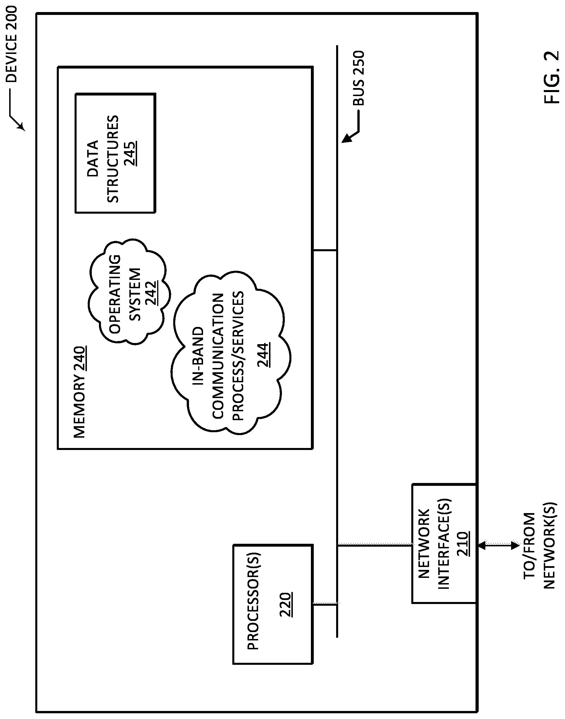
FIG. 2 illustrates a schematic block diagram of an example node/device 200 that may be used with one or more embodiments described herein, e.g., as a software defined networking controller device, sometimes referred to as an application policy infrastructure controller (APIC). Device 200 includes one or more network interfaces 210, one or more processors 220, and a memory 240 interconnected by a system bus 250.
Network interface(s) 210 contain the mechanical, electrical, and signaling circuitry for communicating data over links 106 coupled to one or more nodes/devices shown in data center network 105. Network interfaces 210 may be configured to transmit and/or receive data using a variety of different communication protocols, including, inter alia, TCP/IP, UDP, ATM, synchronous optical networks (SONET), VXLAN, wireless protocols, Frame Relay, Ethernet, Fiber Distributed Data Interface (FDDI), etc. Notably, a physical network interface 210 may also be used to implement one or more virtual network interfaces, such as for Virtual Private Network (VPN) access, known to those skilled in the art.
Memory 240 includes a plurality of storage locations that are addressable by processor(s) 220 and network interfaces 210 for storing software programs and data structures associated with the embodiments described herein. Processor 220 may comprise necessary elements or logic adapted to execute the software programs and manipulate the data structures 245. An operating system 242 (e.g., the Internetworking Operating System, or IOS.RTM., of Cisco Systems, Inc.), portions of which are typically resident in memory 240 and executed by the processor(s), functionally organizes the node by, inter alia, invoking network operations in support of software processes and/or services executing on the device. These software processes and/or services may comprise an in-band communication process/service 244, as described herein.
In addition, in-band communication process (services) 244 may include computer executable instructions executed by the processor 220 to perform functions provided by one or more routing protocols, such as various routing protocols as will be understood by those skilled in the art. These functions may, on capable devices, be configured to manage a routing/forwarding table (a data structure 245) containing, e.g., data used to make routing/forwarding decisions
It will be apparent to those skilled in the art that other processor and memory types, including various computer-readable media, may be used to store and execute program instructions pertaining to the techniques described herein. Also, while the description illustrates various processes, it is expressly contemplated that various processes may be embodied as modules configured to operate in accordance with the techniques herein (e.g., according to the functionality of a similar process). Further, while processes may be shown and/or described separately, those skilled in the art will appreciate that processes may be routines or modules within other processes.
Illustratively, the techniques described herein may be performed by hardware, software, and/or firmware, such as in accordance with in-band communication process 244, which may contain computer executable instructions executed by the processor 220 (or independent processor of network interfaces 210) to perform functions described herein.
FIG. 3 particularly illustrates an example architecture 300 for data center network 105. As shown, architecture 300 includes a fabric 305 formed from a physical underlay of networked devices. Here, network fabric 305 includes spine switches 1-N (spine switch-1-spine switch N), and leaf switches 1-N.
Spine switches 1-N can include, for example, layer 3 (L3) switches, and/or they may also perform L2 functionalities (e.g., supporting certain Ethernet speeds, Ethernet Interfaces, etc.). Generally, spine switches 1-N are configured to lookup destination addresses for a received packet in its respective forwarding table and forward the packet accordingly. However, in some embodiments, one or more of spine switches 1-N may be configured to host a proxy function--here, spine switch 1 operates as a proxy switch. In operation, spine switch 1 matches a received packet to a destination address according to its mapping or routing table on behalf of leaf switches that do not have such mapping. In this fashion, leaf switches forward packets with unknown destination addresses to spine switch 1 for resolution.
For example, spine switch 1 can execute proxy functions to parse an encapsulated packet sent by one or more leaf switches, identify a destination address for the encapsulated packet, and route or forward the encapsulated packet according to the same. In some embodiments, spine switch 1 can perform a local mapping lookup in a database (e.g. a routing table, etc.) to determine a correct locator address of the packet and forward the packet to the locator address without changing certain fields in the header of the packet.
Leaf switches 1-N are interconnected with one or more spine switches to form, in part, fabric 305. Leaf switches 1-N can include access ports (or non-fabric ports) and fabric ports. Fabric ports typically provide uplinks to one or more of the spine switches, while access ports provide connectivity for devices such as device 310 (e.g., a host, a virtual machine (VM), a hypervisor, etc.), endpoint(s) 315, as well as one or more "external networks" (labeled as shown). Leaf switches 1-N may reside at an edge of fabric 305, and can thus represent a physical network edge. In some cases, leaf switches 1-N can include top-of-rack (ToR) switches configured according to a ToR architecture. In other cases, leaf switches 1-N can be virtual switches embedded in one or more servers, or even aggregation switches in any particular topology--e.g., end-of-row (EoR) or middle-of-row (MoR) topologies.
As shown, leaf switches 1-N also connect with devices and/or modules, such as endpoint(s) 315, which represent physical or virtual network devices (e.g., servers, routers, virtual machines (VMs), etc.), external networks, and/or other computing resources. Operatively, network connectivity for fabric 305 flows through leaf switches 1-N, where the leaf switches provide access to fabric 305 as well as interconnectivity between endpoints 315, external networks, etc. Notably, leaf switches 1-N are responsible for applying network policies, routing and/or bridging packets in fabric 305. In some cases, a leaf switch can perform additional functions, including, for example, implementing a mapping cache, sending packets to proxy spines (e.g., when there is a miss in the cache), encapsulating packets, enforcing ingress or egress policies, and the like. In addition, one or more leaf switches may perform virtual switching, including tunneling (e.g., VPN tunneling, etc.), which supports network connectivity through fabric 305, as well as supports communications in an overlay network.
An overlay network typically refers to a network of physical or virtual devices (e.g., servers, hypervisors, applications, endpoints, virtual workloads, etc.), which operate in isolated network segments, important for traffic isolation in various network environments (e.g., multi-tenant, etc.). Operatively, overlay networks isolate traffic amongst tenants on respective network segments within physical and/or virtualized data centers. For example, in a VXLAN overlay network, native frames are encapsulated with an outer IP overlay encapsulation, along with a VXLAN header, and UDP header. Generally, each network segment or VXLAN segment is addressed according to a 24-bit segment ID (e.g., a virtual network identifier or VXLAN network identifier (VNID)), which supports up to 16M VXLAN unique and co-existing network segments in a single administrative domain. The VNID identifies the scope of the inner MAC frame originated by an individual VM; thus, overlapping MAC addresses may exist across segments without resulting in traffic cross-over. The VNID is included in an outer header that encapsulates the inner MAC frame originated by a VM. Due to this encapsulation, VXLAN provides a traffic encapsulation scheme that allows network traffic to be carried across L2 and L3 networks over a logical tunnel, where such logical tunnels can originate and terminate through one or more virtual tunnel endpoints (VTEPs), hosted by a physical switch or physical server and/or implemented in software or other hardware.
As mentioned, leaf switches 1-N support network connectivity through fabric 305 and communications in overlay networks, including such isolated network segments. Further, endpoints 315 may be connected to such overlay networks, and can host virtual workloads, clusters, and/or applications/services that communicate in one or more overlay networks through fabric 305.
Notably, although fabric 305 is illustrated and described as an example leaf-spine architecture employing multiple switches, one of ordinary skill in the art will readily recognize that the subject technology employ any number of devices (e.g., server, routers, etc.) and further, the techniques disclosed herein can be implemented in any network fabric. Indeed, other architectures, designs, infrastructures, and variations are contemplated herein. Further, those skilled in the art will appreciate that the devices shown in fabric 305 are for purposes of illustration, not limitation. Any number of other devices (e.g., route reflectors, etc.) can be included (or excluded) in fabric 305, as appreciated by those skilled in the art.
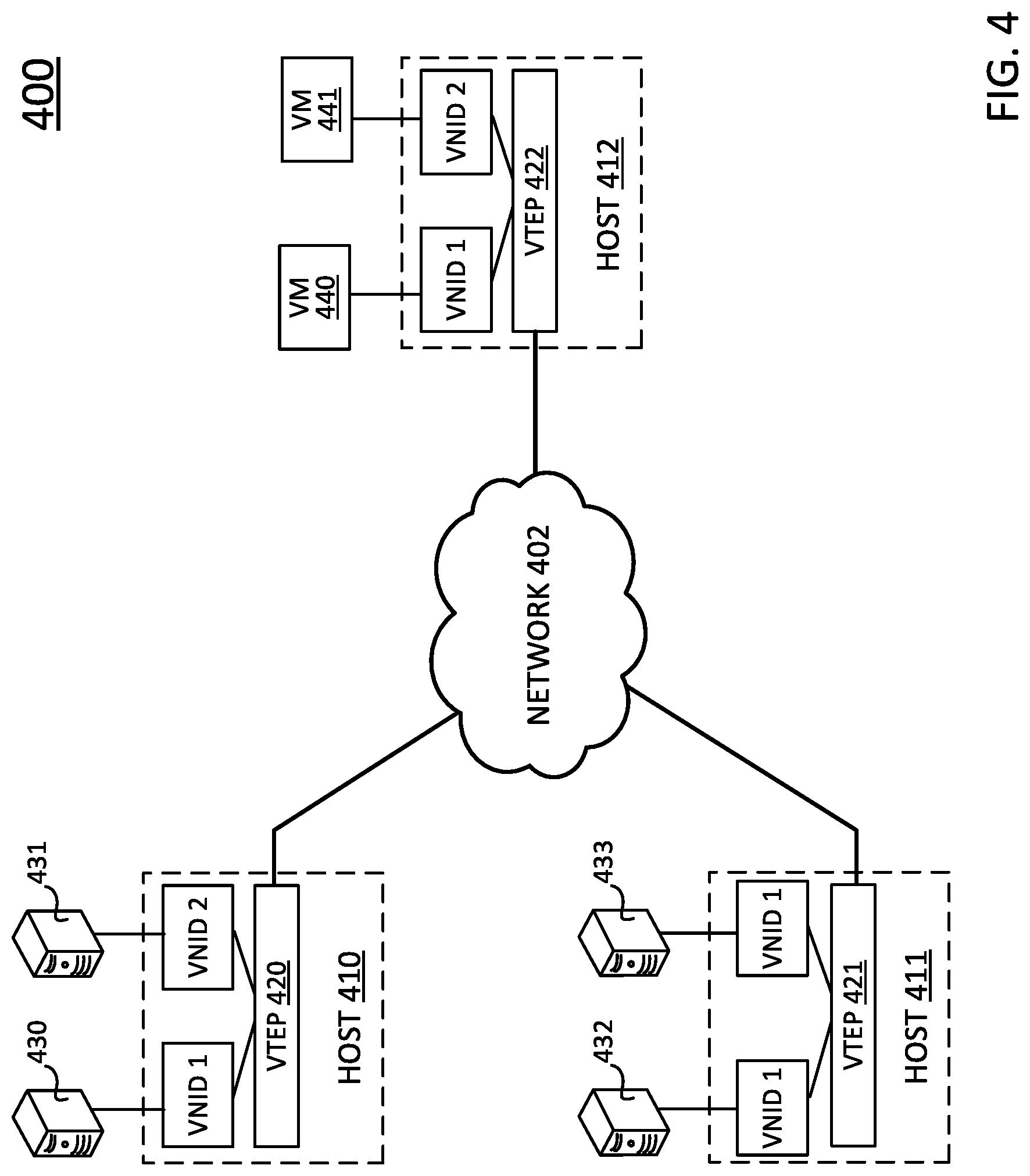
FIG. 4 illustrates an example overlay network architecture 400, including an overlay network 402 interconnecting various network devices/modules--here, host devices 410, 411, and 412. Host devices 410-412 can include, for example, servers, hypervisors, physical switches (e.g., L2/L2 switches), and the like, and can support virtual workloads such as virtual machines, applications, and/or other services executing thereon. Host devices 410-412 may also communicate with other network devices, such as servers 430, 431, 432, and 433, virtual machines (VMs) 440, 441, and the like.
As shown, host devices 410-412 host respective virtual tunnel endpoints (VTEPs) 420, 421, and 422 that communicate in overlay network 402 (which includes one or more leaf switches 1-N of fabric 305 (ref. FIG. 3, above)). VTEPs 420, 421, and 422 represent virtual nodes and/or switches configured to encapsulate and de-encapsulate traffic according to a specific overlay protocol of overlay network 402.
Servers 430-433 and VMs 440, 441 are connected to a respective VTEP and operate in a network segment identified by a corresponding VNID. Notably, each VTEP can include one or more VNIDs--e.g., VTEPs 420 and 422 include VNID 1 and VNID 2, while VTEP 421 includes VNID 1. As discussed above, traffic in overlay network 402 is logically isolated according to network segments identified by specific VNIDs. For example, network devices residing in a network segment identified by VNID 1 cannot be accessed by network devices residing in a network segment identified by VNID 2. More specifically, as shown, server 430 can communicate with server 432 and VM 440 because these devices each reside in the same network segment identified by VNID 1. Similarly, server 431 can communicate with VM 441 because these devices reside in the same network segment identified by VNID 2.
VTEPs 420-422 operatively encapsulate/decapsulate packets for respective network segments identified by respective VNID(s) and exchange such packets in the overlay network 402. As an example, server 430 sends a packet to VTEP 420, which packet is intended for VM 440, hosted by VTEP 422. VTEP 420 determines the intended destination for the packet (VM 440), and encapsulates the packet according to its routing table (e.g., which includes an endpoint-to-switch mappings or bindings for VTEP 422, hosting VM 440), and forwards the encapsulated packet over overlay network 402 to VTEP 422. VTEP 422 encapsulates the packet, and routes the packet to its intended destination--here, VM 440.
In some embodiments, however, the routing table may not include information associated with an intended destination. Accordingly, in such instances, VTEP 410 may be configured to broadcast and/or multicast the packet over overlay network 402 to ensure delivery to VTEP 422 (and thus, to VM 440). In addition, in preferred embodiments, the routing table is continuously and dynamically modified (e.g., removing stale entries, adding new entries, etc.), in order to maintain up-to-date entries in the routing table.
Notably, as is appreciated by those skilled in the art, the views shown herein are provided for purposes of illustration and discussion, not limitation. It is further appreciated that the host devices, servers, and VMs shown in FIG. 4 may represent a single server or VM, and/or multiple servers or VMs, such as a cluster of servers/VMs. Moreover, the VMs may be operatively configured to support virtual workloads, application workloads, resources, and/or services. In addition, in some cases, servers 430-433 can similarly host virtual workloads through respective VMs executing thereon.
As discussed above, data centers include a dynamic and complex network of interconnected devices, which present new challenges regarding performance, latency, reliability, scalability, endpoint migration, traffic isolation, and the like. Increasingly, data centers employ overlay networks to provide proper traffic isolation in multi-tenant environments. Typically, as mentioned, in such multi-tenant environments, traffic (e.g., data packets, etc.) is encapsulated and isolated for a particular network segment using an overlay protocol. Operatively, such overlay protocol often encapsulates a packet with network identifier (e.g., a virtual network identifier (VNID), etc.) to communicate the packet in a specific network segment. Challenges arise in data center networks and overlay networks, due to the complexity of interconnected devices as well as the dynamic nature of resource migration, on-demand scalability, and the like. Accordingly, the techniques described herein particularly provide improvements for managing in-band communications in data center networks (including overlay networks).
Specifically, the techniques described herein dynamically track end-point migration, preserve traffic isolation, and route and/or forward communications amongst network devices/modules (e.g., applications, network controller devices, virtual machines (VMs), and the like). In particular, these techniques are preferably employed by one or more network controller devices, which connect to a network fabric in a data center network. These techniques further offload tasks such as locating endpoints for respective leafs (and/or network controller devices) to one or more proxy devices (or devices with proxy functionality). For example, according to some embodiments discussed in greater detail below, a network controller performs address translation to identify routable addresses, encapsulates packets according to VXLAN encapsulation protocols, and forwards the encapsulated packets to a well-known proxy device (e.g., a proxy spine switch) for address resolution. The proxy device receives the encapsulated packets, determines the appropriate routable addresses, and forwards the encapsulated packets to an endpoint in an appropriate network segment based on a VNID. In operation, the proxy devices maintain, or otherwise update respective routing tables with real-time locations (e.g., addresses) for endpoints in the data center network.
FIG. 5 illustrates another example data center network 500, showing an application centric infrastructure that employs an application policy based solution with scalable distributed enforcement. Generally, data center network 500 supports integration of physical and virtual environments under one declarative policy model for networks, servers, services and security.
Data center network 500 comprises a network fabric 505 that employs an overlay protocol such as a VXLAN overlay protocol. As discussed above, a VXLAN overlay protocol encapsulates/decapsulates and routes packets according to a VXLAN network identifier (VNID) carried in a header field. The VNID identifies a specific virtual network or network segment associated with one or more tenants. In addition, data center network 500 also includes one or more software defined networking controller devices, also referred to as application policy infrastructure controllers (APICs)--here, APIC 1-3--which provide a single point for automation and management.
Fabric 505 includes spine switches 1-N and leaf switches 1-N. As shown, spine switch 1 is designated as a proxy devices or a VXLAN proxy switch (in the VXLAN overlay protocol). Operationally, unknown VXLAN traffic in fabric 505 is forwarded to proxy switches for address resolution and further routing in the data center network and/or within respective overlay networks.
Leaf switches 1 and 2 are further connected to one or more network controller devices APICs 1, 2, and 3, and leaf switches 3 and 4 are connected to host devices 1 and 2. Host devices 1 and 2 can include, for example, physical or virtual devices such as servers, switches, routers, virtual machines, and the like. Here, hosts 1 and 2 host or execute two service VMs 511 and 512. Each VM 511 and VM 512 serves different tenants associated with respective tenant segments in an overlay network.
Overlay networks, as discussed above, are often employed in data center networks to isolate traffic amongst tenants. Typically, a network segment or tenant segment is associated with a tenant using a VNID. In data center network 500, VM 511 communicates in a network segment in common with application ("app") 501, which executes on one or more of APICs 1, 2, and/or 3, and VM 512 communicates in a network segment in common with application ("app") 502, which also executes on one or more APICs 1, 2, and/or 3. Due to network segment isolation, VM 511 and VM 512 may be assigned the same IP address--here, 1.1.1.10.
In operation, app 501 and app 502 send in-band communications (e.g., data packets) over network fabric 505 to respective service VMs 511, 512, and likewise, VMs 511, 512 send in-band communications over network fabric 505 to app 501, 502, respectively. Typically, communications between respective applications and VMs are maintained (e.g., persistent) even if the VM migrates amongst hosts in order to maintain proper routing information.
Regarding traffic isolation for in-band communications, the techniques herein (such as the in-band communication process/services 244) employ a VNID based address translation, where overlapping or shared tenant addresses--here, 1.1.1.10 for VMs 511, 512--are translated into a unique (e.g., different) loopback address according to translation tables indexed or keyed to one or more VNIDs.
For example, a network controller device such as APIC 1 establishes a translation table for in-band traffic in data center network 500 to translate potentially ambiguous addresses. Here, APIC 1 establishes a translation table 520 that includes entries indexed according to a unique address (e.g., loopback address), a VNID for a tenant segment, and/or a routable tenant address. Notably, the routable tenant address in routing table 520 is a public address while the unique address is a private address within data center network 500.
As discussed, although the same or common routable addresses (1.1.1.10, and 1.1.1.1) may be used to identify more than one app, VM, or other computing resource in data center network 500, an encapsulation scheme (e.g., VXLAN) for a packet carrying the common routable address will also include a VNID in a header field. The network controller devices use the common routable address along with the VNID to translate the common routable address into a corresponding unique address. Alternatively (or in addition), the network controller devices may similarly translate a unique address into a common routable address and a VNID so that network devices within fabric 505 can properly route/forward the packet to an appropriate endpoint.
For example, a packet from VM 511 (1.1.1.10) is encapsulated with VNID 10001, while a packet from VM 512 (1.1.1.10) is encapsulated with VNID 10002. The proxy spine switch 1 receives the packets from VM 511 and/or VM 512 and forwards to one of the APICs shown for further translation (APIC 1 for example). APIC 1 receives and decapsulates the packets from proxy spine switch 1 to determine respective VNIDs and routable tenant addresses. APIC 1 further translates the routable tenant addresses based on the VNID into unique addresses (e.g., loopback addresses) for respective applications, and forwards the message to the appropriate application(s). Here, for example, an encapsulated packet originating from VM 511 will have a VXLAN header indicating VNID 10001, an inner source address field of 1.1.1.10, and an inner destination address field of 1.1.1.1, while an encapsulated packet originating from VM 512 will have a VXLAN header indicating 10002, an inner source field of 1.1.1.10 and an inner destination address field of 1.1.1.1. The APIC receiving such packets will translate the inner source/destination address fields (e.g., which include routable addresses) into unique loopback addresses based on translation table 520. Specifically, the inner source address field of 1.1.1.10 in VNID 10001 translates into 192.168.1.2 (corresponding to VM 511), and the inner destination address field of 1.1.1.1 in VNID 10001 translates into 192.168.1.1 (corresponding to app 501). In this fashion, the network device controllers (APICs) can translate potentially ambiguous routable tenant addresses (e.g., common or shared by more than one network device) into a unique address/loopback address.
Similarly, applications--here, apps 1, 2--can likewise have a shared or common routable tenant address when operating in different network segments. For example, the same address for app 501, 502 (1.1.1.1) is translated into different loopback addresses (192.168.1.1 and 192.168.1.3) for different tenant segments based on the VNID associated with a particular network segment. Here, app 501 and app 502 are bound to IP address 192.168.1.1 and 192.168.1.3, respectively, and communicate with VM 511, 512, respectively. App 501 sends a packet intended for VM 511 to one of the network controller devices (e.g., APIC 1) for address translation. The packet from app 501 includes 192.168.1.1 and 192.168.1.2 as an inner source and a destination IP address, respectively. APIC 1 receives the packet from app 501 and translates the inner source and destination IP address into routable tenant addresses 1.1.1.1 and 1.1.1.10, respectively. APIC 1 further encapsulates the packet from app 501 with VNID 10001 in a VXLAN header based on translation table 520.
The in-band communication techniques discussed above consolidate address translation in one or more network controller devices while respecting traffic isolation between different network segments. Notably, the translation tables used by the network controller devices may be local and/or distributed across multiple networks devices. Further, as discussed, the routing tables include entries keyed or indexed according to VNIDs, routable tenant addresses, and/or unique (loopback) addresses. Based on a combination of a VNID, a routable tenant address, and/or a unique address, the network controller device can translate between routable tenant addresses and unique addresses and/or identify an appropriate VNID for a packet (which VNID is used when encapsulating the packet for forwarding to the proxy device(s)).
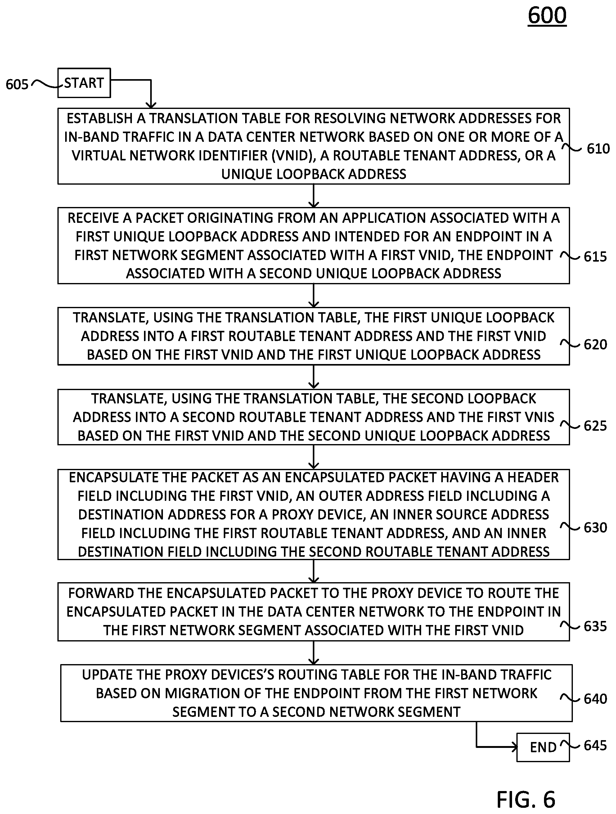
FIG. 6 illustrates an example simplified procedure 600 for managing in-band communications over an overlay network, particularly from the perspective of a network controller device (e.g., APIC(s) 1-3). Procedure 600 begins at step 605 and continues on to step 610 where, as discussed above, the network controller device establishes a translation table (e.g., local, distributed, etc.) for resolving network addresses for in-band traffic in a data center network based on one or more of a virtual network identifier (VNID), a routable tenant address, or a unique loopback address.
Procedure 600 continues to step 615, where operatively, the network controller device receives a packet originating from an application associated with a first unique loopback address. Notably, the packet is also intended for an endpoint in a first network segment associated with a first VNID, and the endpoint is associated with a second unique loopback address. The network controller, in steps 620 and 625, further translates, using the translation table (e.g., translation table 520), the first unique loopback address into a first routable tenant address and a first VNID, and the second unique loopback address into a second routable tenant address and the first VNID based the first unique loopback address and the second unique loopback address, respectively. Once translated, the network controller encapsulates (e.g., VXLAN encapsulation), in step 625, the packet as an encapsulated packet having a header field including the first VNID, an outer address field including an address for a proxy device (to forward to a proxy device in the network fabric), an inner source address field including the first routable tenant address, and an inner destination field including the second routable tenant address.
The network controller device further forwards the encapsulated packet, in step 635, to the proxy device to route the encapsulated packet in the data center network to the endpoint in the first network segment associated with the first VNID. The proxy device, as discussed above, receives and decapsulates the packet to determine appropriate routing/forwarding and sends the packet to the endpoint. Notably, in some embodiments, the proxy device tunnels the packet to the endpoint (e.g., in the overlay network/first network segment).
In addition, the proxy device may also update its routing table, in step 640, based on migration of the endpoint from the first network segment to a second network segment, or other such dynamic movement of computing resources. Procedure 600 subsequently ends at step 645, but may continue on to step 615 where the network controller device receives packets from the application (or other applications).
FIG. 7 illustrates another example simplified procedure 700 for managing in-band communications over an overlay network, again from the perspective of a network controller device (e.g., APIC(s) 1-3). Here, procedure 700 describes steps for translating in-band traffic from one or more endpoints (e.g., VMs 511, 512, etc.) to one or more applications (e.g., app 1, app 2, etc.).
Procedure 700 begins at step 705 and continues on to step 710 where, similar to procedure 600, the network controller device establishes a translation table (e.g., local, distributed, etc.) for resolving network addresses for in-band traffic in a data center network based on one or more of a virtual network identifier (VNID), a routable tenant address, or a unique loopback address. Notably, the translation table may be the same as the one provided in procedure 600.
Procedure 700 continues to step 715 where the network controller device decapsulates a second packet originating from the endpoint in first network segment to determine the first VNID, the second routable tenant address, and the first routable tenant address.
The network controller device further translates, in steps 720, 725 the first routable tenant address and the second routable tenant address (e.g., using translation table 520) into the first unique loopback address and the second unique loopback address, respectively, based at least on the first VNID. The network controller device further forwards the second packet to the appropriate application associated with the first unique loopback address. Procedure 700 subsequently ends at step 735, but may continue on to step 715 where the network controller device decapsulates packets from endpoints in corresponding network segments.
It should be noted that certain steps within procedures 600-700 may be optional, and further, the steps shown in FIGS. 6-7 are merely examples for illustration--certain other steps may be included or excluded as desired. Further, while a particular order of the steps is shown, this ordering is merely illustrative, and any suitable arrangement of the steps may be utilized without departing from the scope of the embodiments herein. Moreover, while procedures 600-700 are described separately, certain steps from each procedure may be incorporated into each other procedure, and the procedures are not meant to be mutually exclusive.
In addition to the embodiments described above, additional embodiments of this disclosure provide a scalable VNID mapping table proportional in size with VNIDs for network segments and/or VRF instances in an overlay network. For example, according to one of these embodiments, the in-bound communication techniques leverage Linux VRF instances and a universal TUN/TAP driver and, in particular, tie the fabric VRF instances and the Linux VRF instances together by mapping a TAP interface with a VNID for a network segment.
In detail, FIG. 8 illustrates an example network architecture 800 that supports scalable VNID based mapping techniques. As shown in network architecture 800, apps 501, 502, 810, and 811 communicate over respective interfaces (e.g., TAP/TUN interfaces, bond interface 805, etc.) with one or more computing resources--here, service virtual machines (VMs) 511-N. Network architecture also includes an in-band module 815 (e.g., a user space daemon, etc.) that manages and/or otherwise coordinates forwarding traffic between the applications, including respective VRF devices 801, 802, 812, and VMs 511, 512 (through VM-N).
In operation, a network controller (not shown) (e.g., one of APICs 1-3) creates a Linux VRF instance for each fabric VRF instance. As discussed below, a fabric VRF instance refers to a context for a network segment associated with a VNID (e.g., a tenant network segment). As shown, Linux VRF instances incorporate the fabric VRF context in a VRF device--e.g., VRF devices 801, 802, and 812. The network controller further creates or instantiates an enslaved interface for each VRF instance/device--e.g., interface 1, interface 2, interface 3--which are illustrated as TAP/TUN interfaces. Applications (apps 501, 502, 810, 812) are tied, respectively, to interfaces on corresponding VRF devices. Notably, apps 810 and 811 operate in the same network segment (e.g., VNID 10003) and shown as tied or bound to a shared interface 3 on VRF device 812.
In general, in-band module 815 executes or runs on the network controller and constructs a mapping table 820 to map interfaces with VNIDs (associated with respective network segments). In-band module 815 maintains mapping table 820 and performs VXLAN tunneling for traffic exchanged between applications and computing resources (here, VMs). In-band module 815 updates entries in mapping table 820 when interfaces are created (and/or deleted).
As shown, mapping table 820 maps an aggregation of interfaces to respective VNIDs used by the fabric VRF. Mapping table 820 maps each interface with a corresponding VNID associated with a network segment. For example, interface 1 is mapped to VNID 10001 used by the fabric VRF or network segment common with VM 511. Accordingly, in-band module 815 directs traffic destined for app 501 (which operates in the network segment associated with VNID 10001) to interface 1. In greater detail, consider a packet (e.g., a VXLAN encapsulated packet) sent from VM 511 to app 501, coming in from a channel bonding interface 805 (e.g., which represents a channel bonding interface and/or an aggregation of interfaces). In-band module 815 listens, monitors, or otherwise receives the encapsulated packet from bond interface 805 on an UDP socket bound to a reserved port number. In-band module 815 further performs decapsulation (e.g., VXLAN decapsulation) and determines the VNID--here, VNID 10001--from the encapsulated packet header. In-band module 815 identifies an associated interface (e.g., interface 1) and corresponding enslaved VRF device (e.g., VRF device 1) based on a mapping table lookup. In-band module 815 then writes the decapsulated packet into interface 1, which is received by app 501 tied to VRF device 801. Conversely, app 501 sends a packet to VM 511, the packet is forwarded to interface 1 because interface 1 is the next hop of a default route in VRF device 801. The packet is picked up by in-band module 815, which listens to traffic on interface 1. In-band module 815 performs VXLAN encapsulation, using VNID 10001 in the VXLAN header. The VNID for the received packet is determined by mapping table 820 and a lookup, using interface 1 as the key. In-band module 815 further sends the encapsulated packet through the UDP socket to bond interface 805.
As shown in mapping table 820, each VNID is mapped to a single interface. In this fashion, mapping table 820 remains proportional to a number of VRF instances (e.g., network segments) mapped to respective interfaces. Given a large number of fabric VRF instances, mapping table 820 scales efficiently, because its size is unrelated to the number of service VMs in a fabric VRF.
FIG. 9 is an example of simplified procedure 900 for managing in-band communications over an overlay network, particularly from the perspective of a network controller device (e.g., one of APICs 1-3 shown in FIG. 5).
Procedure 900 begins at step 905 and continues on to step 910 where, as discussed above, the network controller device establishes a virtual routing and forwarding (VRF) instance for each network segment of a plurality of network segments. The network controller, at step 915, further instantiates, for each VRF instance, at least one bound interface on a VRF device. As discussed, the bound interface can include, for example, a TAP/TUN interface (e.g., interfaces 1-3 in FIG. 8), which are enslaved to respective VRF devices. Procedure 900 continues to step 920 where the network controller device maps one or more virtual network identifiers (VNIDs) to one or more respective bound interfaces on corresponding VRF devices. For example, referring again to mapping table 820, the network controller device (e.g., and/or in-band module 815, which executes on the network controller device) maps an interface on respective VRF device to a VNID associated with a network segment.
Further, in step 925, the network controller device links or associates one or more applications with the VRF device, and thus, links the one or more applications the respective interface(s) on the VRF device. Procedure 900 continues to step 930 where the network controller and/or the application executing/running on the network controller sends or writes a packet to the linked VRF device, which is a default next hop, in order to route the packet in a network segment over an interface of the VRF device. Typically, an in-band module executing on the network controller device listens to the tap interface, receives the packet, determines the VNID mapped to the interface from a mapping table (e.g., mapping table 820), and tunnels the packet to an appropriate computing resource (e.g., a service VM). Procedure 900 subsequently ends at step 935, but may continue on to step 910 where the network controller device establishes VRF instances for network segments, discussed above.
It should be noted that certain steps within procedure 900 may be optional, and further, the steps shown in FIG. 9 are merely examples for illustration--certain other steps may be included or excluded as desired. Further, while a particular order of the steps is shown, this ordering is merely illustrative, and any suitable arrangement of the steps may be utilized without departing from the scope of the embodiments herein. In addition, although procedure 900 is described with respect to a network controller device, certain operations may be executed by devices or modules running on the network controller device (e.g., in-band module 815, etc.).
The techniques described herein manage in-band traffic in a data center network, and in particular, traffic within network segments. These techniques further support endpoint migration for in-band communications using local and/or aggregated translation and mapping tables that may index entries according to VNIDs, tenant addresses, unique (loopback) addresses, bound network interfaces (TAP/TUN interfaces), and combinations thereof.
While there have been shown and described illustrative embodiments for managing in-band communications in a data center network, it is to be understood that various other adaptations and modifications may be made within the spirit and scope of the embodiments herein. For example, the embodiments have been shown and described herein with relation to network switches and a control plane comprising the network switches. However, the embodiments in their broader sense are not as limited, and may, in fact, be used with any number of network devices (e.g., routers), and the like. In addition, the embodiments are shown with certain devices/modules performing certain operations (e.g., APICs 1-3, proxy spine switch 1, in-band module 715, and the like), however, it is appreciated that various other devices may be readily modified to perform operations without departing from the sprit and scope of this disclosure. Moreover, although the examples and embodiments described herein particularly refer to VXLAN protocols, the embodiments in their broader sense may be applied to any known encapsulation protocols, as is appreciated by those skilled in the art.
The foregoing description has been directed to specific embodiments. It will be apparent, however, that other variations and modifications may be made to the described embodiments, with the attainment of some or all of their advantages. For instance, it is expressly contemplated that the components and/or elements described herein can be implemented as software being stored on a tangible (non-transitory) computer-readable medium, devices, and memories (e.g., disks/CDs/RAM/EEPROM/etc.) having program instructions executing on a computer, hardware, firmware, or a combination thereof. Further, methods describing the various functions and techniques described herein can be implemented using computer-executable instructions that are stored or otherwise available from computer readable media. Such instructions can comprise, for example, instructions and data which cause or otherwise configure a general purpose computer, special purpose computer, or special purpose processing device to perform a certain function or group of functions. Portions of computer resources used can be accessible over a network. The computer executable instructions may be, for example, binaries, intermediate format instructions such as assembly language, firmware, or source code. Examples of computer-readable media that may be used to store instructions, information used, and/or information created during methods according to described examples include magnetic or optical disks, flash memory, USB devices provided with non-volatile memory, networked storage devices, and so on. In addition, devices implementing methods according to these disclosures can comprise hardware, firmware and/or software, and can take any of a variety of form factors. Typical examples of such form factors include laptops, smart phones, small form factor personal computers, personal digital assistants, and so on. Functionality described herein also can be embodied in peripherals or add-in cards. Such functionality can also be implemented on a circuit board among different chips or different processes executing in a single device, by way of further example. Instructions, media for conveying such instructions, computing resources for executing them, and other structures for supporting such computing resources are means for providing the functions described in these disclosures. Accordingly this description is to be taken only by way of example and not to otherwise limit the scope of the embodiments herein. Therefore, it is the object of the appended claims to cover all such variations and modifications as come within the true spirit and scope of the embodiments herein.
* * * * *
References
-
asd.gov.au/infosec/top-mitigations/top-4-strategies-explained.htm
-
dambala.com9pages
-
mdpi.com/joumal/entropy
-
www/cisco.com/c/en/us/support/docs/security-vpn/lock-key/7604-13.html
-
researchgate.net/publication/221536306
-
internetperils.com
-
searchdatacenter.techtarget.com/news/118820/Get-to-know-your-data-center-with-CMDB
-
docs.hol.vmware.com/HOL-2013/holsdc-1301_html_en
-
jfrog.com/confluence/display/DA/Home
-
neverfailgroup.com/products/it-continuity-architect
-
pathwaysystems.com/company-blog
-
-
arxiv.org/abs/1406.2098
D00000
D00001
D00002
D00003
D00004
D00005
D00006
D00007
D00008
D00009
XML
uspto.report is an independent third-party trademark research tool that is not affiliated, endorsed, or sponsored by the United States Patent and Trademark Office (USPTO) or any other governmental organization. The information provided by uspto.report is based on publicly available data at the time of writing and is intended for informational purposes only.
While we strive to provide accurate and up-to-date information, we do not guarantee the accuracy, completeness, reliability, or suitability of the information displayed on this site. The use of this site is at your own risk. Any reliance you place on such information is therefore strictly at your own risk.
All official trademark data, including owner information, should be verified by visiting the official USPTO website at www.uspto.gov. This site is not intended to replace professional legal advice and should not be used as a substitute for consulting with a legal professional who is knowledgeable about trademark law.