Plastic tank
Kahler , et al. February 23, 2
U.S. patent number 10,926,508 [Application Number 16/137,401] was granted by the patent office on 2021-02-23 for plastic tank. This patent grant is currently assigned to MAGNA Energy Storage Systems GesmbH. The grantee listed for this patent is MAGNA STEYR Fuel Systems GesmbH. Invention is credited to Harald Humenberger, Bernd Kahler, Rainer Puchleitner.

| United States Patent | 10,926,508 |
| Kahler , et al. | February 23, 2021 |
Plastic tank
Abstract
A plastic tank for a motor vehicle and a method for producing such a plastic tank for a motor vehicle. The tank shell has a multi-layered structure, including at least one layer composed of high-density polyethylene, at least one barrier layer, and at least one regrind layer composed of recycled plastic arranged between the at least one layer composed of high-density polyethylene and the at least one barrier layer. The at least one regrind layer and/or the at least one layer composed of high-density polyethylene contains spherical fillers or fibrous fillers.
| Inventors: | Kahler; Bernd (Graz, AT), Puchleitner; Rainer (Graz, AT), Humenberger; Harald (St. Ruprecht, AT) | ||||||||||
|---|---|---|---|---|---|---|---|---|---|---|---|
| Applicant: |
|
||||||||||
| Assignee: | MAGNA Energy Storage Systems
GesmbH (Sinabelkirchen, AT) |
||||||||||
| Family ID: | 1000005375712 | ||||||||||
| Appl. No.: | 16/137,401 | ||||||||||
| Filed: | September 20, 2018 |
Prior Publication Data
| Document Identifier | Publication Date | |
|---|---|---|
| US 20190091978 A1 | Mar 28, 2019 | |
Foreign Application Priority Data
| Sep 26, 2017 [EP] | 17193121 | |||
| Current U.S. Class: | 1/1 |
| Current CPC Class: | B32B 27/32 (20130101); B60K 15/03177 (20130101); B32B 7/12 (20130101); B32B 27/30 (20130101); B29C 49/04 (20130101); B32B 27/20 (20130101); B65D 1/0223 (20130101); B60K 15/03 (20130101); B65D 1/0215 (20130101); B65D 1/28 (20130101); B32B 27/302 (20130101); B32B 37/12 (20130101); B32B 27/08 (20130101); B32B 27/306 (20130101); B32B 1/02 (20130101); Y10T 428/1372 (20150115); B32B 2262/101 (20130101); B60K 2015/03046 (20130101); B32B 2605/00 (20130101); Y10T 428/1352 (20150115); B32B 2264/101 (20130101); B32B 2250/246 (20130101); B60K 2015/03493 (20130101); Y10T 428/1383 (20150115); B32B 2250/05 (20130101); Y10T 428/1379 (20150115) |
| Current International Class: | B32B 1/02 (20060101); B32B 27/30 (20060101); B32B 7/12 (20060101); B32B 27/08 (20060101); B32B 27/20 (20060101); B32B 27/32 (20060101); B29C 49/04 (20060101); B65D 1/28 (20060101); B32B 37/12 (20060101); B60K 15/03 (20060101); B65D 1/02 (20060101) |
References Cited [Referenced By]
U.S. Patent Documents
| 6589620 | July 2003 | Abu-Isa |
| 2003/0198768 | October 2003 | Delbarre |
| 2011/0151165 | June 2011 | Zhu et al. |
| 2011/0226777 | September 2011 | Asahara |
| 2012/0074028 | March 2012 | Martin |
| 102010046378 | Mar 2012 | DE | |||
| 1122113 | Aug 2001 | EP | |||
| 1245381 | Oct 2002 | EP | |||
| 2004035295 | Apr 2004 | WO | |||
Attorney, Agent or Firm: Jordan IP Law, LLC Vaughn; Todd A.
Claims
What is claimed is:
1. A tank for a motor vehicle, the tank comprising, a multi-layered structure that includes: an outermost layer composed of high-density polyethylene; an innermost layer composed of high-density polyethylene; a first regrind layer composed of recycled plastic arranged on the outermost layer; a second regrind layer composed of recycled plastic arranged on the innermost layer; and a barrier layer arranged between the first regrind layer and the second regrind layer, wherein the first regrind layer contains spherical fillers or fibrous fillers and the second regrind layer contains spherical fillers or fibrous fillers.
2. The tank of claim 1, further comprising a first adhesion promoter layer to connect the barrier layer to the first regrind layer.
3. The tank of claim 2, further comprising a second adhesion promoter layer to connect the barrier layer to the second regrind layer.
4. The tank of claim 1, wherein the barrier layer is composed of ethylene vinyl alcohol copolymer.
Description
CROSS-REFERENCE TO RELATED APPLICATIONS
The present application claims priority to European Patent Publication No. EP17193121.5 (filed on Sep. 26, 2017), which is hereby incorporated by reference in its entirety.
TECHNICAL FIELD
Embodiments relate to a plastic tank for a motor vehicle and a method for producing such a plastic tank for a motor vehicle.
BACKGROUND
Plastic tanks for motor vehicles are presently frequently used as fuel tanks, i.e., to accommodate the fuel for operating the motor vehicle.
Since such plastic tanks have to meet various mechanical and chemical requirements, equipping plastic tanks with tank shells, which consist of multiple layers of various materials, is already known. In particular, for example, a barrier layer can be used to reduce the passage of hydrocarbons. Such a barrier layer can be formed, for example, as an inner layer of a tank shell and can be composed of ethylene vinyl alcohol copolymer (EVOH).
It is also already known that plastic can be used not only in newly produced, primary form, but rather also, for example, in reprocessed recycled form, as so-called "regrind." In this case, plastic wastes and/or plastic residues, which are often provided in the form of a mixture of various plastics, are ground into a ground material, the regrind, and supplied in this granular form to a further processing process, in particular, a production process.
The use of such regrinds is also desirable from an ecological viewpoint for plastic tanks of the above-described type, but tank shells composed of regrind can hardly have the properties required for a fuel tank in a motor vehicle, in particular, with respect to pressure and temperature stability.
SUMMARY
Embodiments relate to an enhanced structure for a plastic tank for a motor vehicle and, a corresponding method for producing such a plastic tank.
Embodiments relate to such a plastic tank that has good mechanical and chemical properties and, at the same time, may be produced ecologically and economically.
In accordance with embodiments, a plastic tank for a motor vehicle, may comprise a tank shell having a multi-layered structure including a plurality of layers that include at least one layer composed of high-density polyethylene (HDPE), at least one barrier layer, and at least one regrind layer, wherein the regrind layer and/or the HDPE layer contains spherical or fibrous fillers.
In accordance with embodiments, a plastic tank may be constructed having a plurality of layers, wherein the base of the tank and the production method is substantially high-density polyethylene, i.e., HDPE. In addition to a barrier layer for hydrocarbons, a regrind layer is used, i.e., a layer composed of a recycled plastic, in particular, a plastic mixture which has been ground to form a plastic granulate, and in this form, is processed into a layer of the tank shell of the plastic tank.
In accordance with embodiments, in order to achieve the required mechanical stability of the tank shell in spite of properties of the regrind which are modestly suitable per se, a regrind having spherical or fibrous fillers may be used. Alternatively or additionally, spherical or fibrous fillers may also be added to the primary HDPE layer in order to achieve the desired mechanical properties for the overall layer structure of the tank shell. In particular, the regrind may be produced from production residues of the same multi-layered plastic tank. For example, the regrind may therefore comprise a high proportion of HDPE, and may in itself be obtained from regrind in addition to the primary HDPE, and the regrind can comprise EVOH from a barrier layer. The regrind layer may be produced from a regrind material, i.e., from a recycled plastic granulate.
In accordance with embodiments, the tank shell may comprise, from the inside to the outside: a layer composed of HDPE, a regrind layer, a barrier layer, a further regrind layer, a further layer composed of HDPE. In this case, the further regrind layer preferably, like the regrind layer, contains spherical or fibrous fillers. Alternatively or additionally, the further HDPE layer can also contain spherical or fibrous fillers. Such fillers may, for example, comprise glass beads, perlite, and/or glass fibres.
In accordance with embodiments, the barrier layer may be connected to the regrind layer via an intervening adhesion promoter layer. If a further regrind layer is provided, it may also be connected to the barrier layer via an adhesion promoter layer.
In accordance with embodiments, a method for producing a plastic tank for a motor vehicle may comprise at least one of: selectively adding fillers in a targeted manner to a regrind material of the regrind layer. The fillers may be added to the regrind material before the processing to form a plastic tank. The fillers may be introduced exclusively into the regrind layer or into the regrind layers. The remaining layers of the plastic tank preferably do not have fillers.
In accordance with embodiments, the regrind layer may be produced with the aid of an extruder from a regrind material, i.e., from a recycled plastic granulate.
In accordance with embodiments, the fillers may be admixed to the regrind material before the extrusion and subsequently the regrind material, already comprising the fillers, is supplied to the extruder.
In accordance with embodiments, during the extrusion, the fillers may be supplied to the regrind material through a channel of the extruder, in particular, a color channel.
DRAWINGS
Embodiments will be illustrated by way of example in the drawings and explained in the description below.
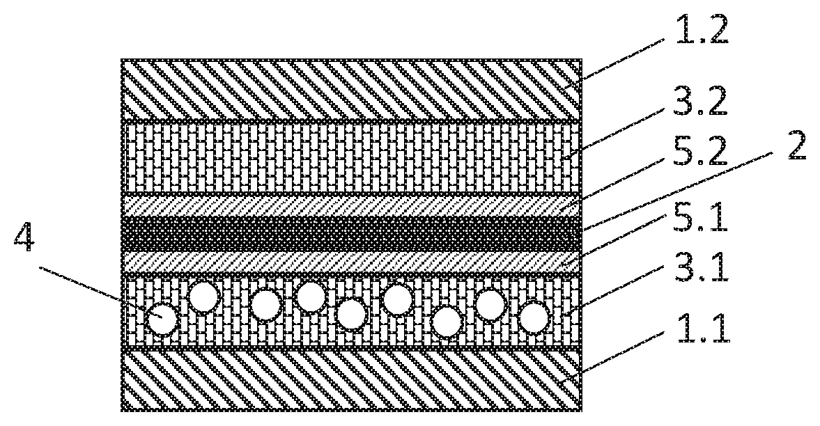
FIG. 1 illustrates a schematic sectional view of a tank shell of a plastic tank for a motor vehicle, in accordance with embodiments.
DESCRIPTION
As illustrated in FIG. 1, a plastic tank for a motor vehicle is provided having a multi-layered structure. The tank shell of the plastic tank has a plurality of layers, including from the inside (shown on the bottom of FIG. 1) to the outside (shown on the top of FIG. 1), an outermost layer 1.1 composed of HDPE, a first intermediary layer 3.1 composed of a regrind material, a first adhesion promoter layer 5.1, a barrier layer 2 composed of EVOH, a second adhesion promoter layer 5.2, a second intermediary layer 3.2 composed of a regrind material, and an innermost layer 1.2 composed of HDPE.
In accordance with embodiments, the first regrind layer 3.1 contains spherical or fibrous fillers 4, for example, glass beads, perlite, and/or glass fibres. The second regrind layer 3.2 may also contain such fibrous fillers 4. One or both of the HDPE layers 1.1, 1.2 may also contain the same fibrous fillers 4. Alternatively, the first regrind layer 3.1 and the second regrind layer 3.2 may exclusively contain spherical or fibrous fillers 4 such that the remaining layers of the plastic tank do not contain fibrous fillers.
In accordance with embodiments, the proportion of the fibrous fillers 4 in a layer, such as, for example, the first regrind layer 3.1 and the second regrind layer 3.2, may be between 1% and 80%, and particularly, between 10% to 50%.
In accordance with embodiments, the layer thicknesses may be allocated as follows: the first HDPE layer 1.1 and the second HDPE layer 1.2 may each occupy approximately 22% of the overall tank shell thickness, the first regrind layer 3.1 and the second regrind layer 3.2 may each occupy approximately 25% of the overall tank shell thickness, the harrier layer 2 may occupy approximately 3% of the overall tank shell thickness, and the first adhesion promoter layer 5.1 and the second adhesion promoter layer 5.2 may each approximately 1.5% of the overall tank shell thickness.
The terms "coupled," "attached," or "connected" may be used herein to refer to any type of relationship, direct or indirect, between the components in question, and may apply to electrical, mechanical, fluid, optical, electromagnetic, electromechanical or other connections. In addition, the terms "first," "second," etc. are used herein only to facilitate discussion, and carry no particular temporal or chronological significance unless otherwise indicated.
Those skilled in the art will appreciate from the foregoing description that the broad techniques of the embodiments can be implemented in a variety of forms. Therefore, while the embodiments have been described in connection with particular examples thereof, the true scope of the embodiments should not be so limited since other modifications will become apparent to the skilled practitioner upon a study of the drawings, specification, and following claims.
LIST OF REFERENCE SIGNS
1.1 Inner HDPE layer 1.2 Outer HDPE layer 2 Barrier layer 3.1 First regrind layer 3.2 Second regrind layer 4 Fillers 5.1 First adhesion promoter layer 5.2 Second adhesion promoter layer
* * * * *
D00000
D00001
XML
uspto.report is an independent third-party trademark research tool that is not affiliated, endorsed, or sponsored by the United States Patent and Trademark Office (USPTO) or any other governmental organization. The information provided by uspto.report is based on publicly available data at the time of writing and is intended for informational purposes only.
While we strive to provide accurate and up-to-date information, we do not guarantee the accuracy, completeness, reliability, or suitability of the information displayed on this site. The use of this site is at your own risk. Any reliance you place on such information is therefore strictly at your own risk.
All official trademark data, including owner information, should be verified by visiting the official USPTO website at www.uspto.gov. This site is not intended to replace professional legal advice and should not be used as a substitute for consulting with a legal professional who is knowledgeable about trademark law.