Device and method for creating a panoramic x-ray recording using a first semi-transparent x-ray screen and a second semi-transparent x-ray screen
Ecabert , et al. February 23, 2
U.S. patent number 10,925,569 [Application Number 15/473,919] was granted by the patent office on 2021-02-23 for device and method for creating a panoramic x-ray recording using a first semi-transparent x-ray screen and a second semi-transparent x-ray screen. This patent grant is currently assigned to Siemens Healthcare GmbH. The grantee listed for this patent is SIEMENS HEALTHCARE GMBH. Invention is credited to Olivier Ecabert, Alexander Gemmel, Gerhard Kleinszig, Birgi Tamersoy.


| United States Patent | 10,925,569 |
| Ecabert , et al. | February 23, 2021 |
Device and method for creating a panoramic x-ray recording using a first semi-transparent x-ray screen and a second semi-transparent x-ray screen
Abstract
During the generation of a panoramic x-ray recording, the use of semi-transparent x-ray screens allows the patient's x-ray exposure to be reduced when partial x-ray images are created, in spite of relatively large overlapping areas between the partial x-ray images.
| Inventors: | Ecabert; Olivier (Ebermannstadt, DE), Gemmel; Alexander (Erlangen, DE), Kleinszig; Gerhard (Forchheim, DE), Tamersoy; Birgi (Erlangen, DE) | ||||||||||
|---|---|---|---|---|---|---|---|---|---|---|---|
| Applicant: |
|
||||||||||
| Assignee: | Siemens Healthcare GmbH
(Erlangen, DE) |
||||||||||
| Family ID: | 58358417 | ||||||||||
| Appl. No.: | 15/473,919 | ||||||||||
| Filed: | March 30, 2017 |
Prior Publication Data
| Document Identifier | Publication Date | |
|---|---|---|
| US 20170281109 A1 | Oct 5, 2017 | |
Foreign Application Priority Data
| Mar 30, 2016 [DE] | 102016205176.8 | |||
| Current U.S. Class: | 1/1 |
| Current CPC Class: | A61B 6/4035 (20130101); A61B 6/545 (20130101); A61B 6/5211 (20130101); A61B 6/5205 (20130101); A61B 6/04 (20130101); A61B 6/4085 (20130101); A61B 6/542 (20130101); A61B 6/544 (20130101); A61B 6/469 (20130101); A61B 6/467 (20130101); A61B 6/5229 (20130101); A61B 6/54 (20130101); A61B 6/4208 (20130101); A61B 6/42 (20130101); A61B 6/4258 (20130101); A61B 6/40 (20130101); A61B 6/461 (20130101); A61B 6/0487 (20200801); A61B 6/5235 (20130101); A61B 6/0407 (20130101); A61B 6/46 (20130101); A61B 6/44 (20130101); A61B 6/52 (20130101); A61B 6/4042 (20130101); A61B 6/4435 (20130101); A61B 6/4429 (20130101); A61B 6/5241 (20130101); A61B 6/06 (20130101) |
| Current International Class: | A61B 6/00 (20060101); A61B 6/06 (20060101); A61B 6/04 (20060101) |
| Field of Search: | ;378/62,63,98.12,147,149-152,156-159,162,165 |
References Cited [Referenced By]
U.S. Patent Documents
| 4093864 | June 1978 | Hahn |
| 4672652 | June 1987 | Huttenrauch |
| 4817125 | March 1989 | Sklebitz |
| 4897861 | January 1990 | Schaefer |
| 5048067 | September 1991 | Horbaschek |
| 5107529 | April 1992 | Boone |
| 5170425 | December 1992 | Haendle |
| 5278887 | January 1994 | Chiu et al. |
| 5282254 | January 1994 | Chiu |
| 5369678 | November 1994 | Chiu |
| 5923724 | July 1999 | Soukal |
| 6036362 | March 2000 | Schmitt |
| 6094474 | July 2000 | Vezina |
| 6101238 | August 2000 | Murthy |
| 6330299 | December 2001 | Curtis |
| 6463121 | October 2002 | Milnes |
| 6501828 | December 2002 | Popescu |
| 6563909 | May 2003 | Schmitz |
| 6735273 | May 2004 | Flohr |
| 6940948 | September 2005 | Tretiakov |
| 6944269 | September 2005 | Schmitt |
| 7110497 | September 2006 | Halsmer et al. |
| 7120231 | October 2006 | Spahn |
| 7245691 | July 2007 | Kiyono |
| 7272208 | September 2007 | Yatsenko |
| 7340033 | March 2008 | Mollus |
| 7344305 | March 2008 | Kuzmanovic |
| 7356123 | April 2008 | Mollus |
| 7433503 | October 2008 | Cherek |
| 7522701 | April 2009 | Jensen |
| 7549798 | June 2009 | Watanabe |
| 7564038 | July 2009 | Endo |
| 7715521 | May 2010 | Sakaida |
| 7724874 | May 2010 | Kameshima |
| 7734007 | June 2010 | Kargar |
| 7869637 | January 2011 | Baumgart |
| 8396184 | March 2013 | Shinno |
| 8605861 | December 2013 | Sipiorski |
| 8956044 | February 2015 | Hummel |
| 8971493 | March 2015 | Zhang |
| 8977015 | March 2015 | Bohm |
| 9008267 | April 2015 | Roberts |
| 9078620 | July 2015 | Shin |
| 9109998 | August 2015 | Nathaniel |
| 9121809 | September 2015 | Cox |
| 9149247 | October 2015 | Lee |
| 9254109 | February 2016 | Becker |
| 9259200 | February 2016 | Mountney |
| 9375192 | June 2016 | Schildkraut |
| 9462985 | October 2016 | Hu |
| 9480443 | November 2016 | Feuerlein |
| 9545234 | January 2017 | Bernhardt |
| 9610053 | April 2017 | Okuno |
| 9649086 | May 2017 | Tajima |
| 9697923 | July 2017 | Tsuji |
| 9700270 | July 2017 | Tateishi |
| 9700277 | July 2017 | Okuno |
| 9814435 | November 2017 | Kim |
| 9820705 | November 2017 | Kim |
| 9820709 | November 2017 | Melman |
| 9848840 | December 2017 | Ohashi |
| 9861329 | January 2018 | Shin |
| 9931087 | April 2018 | Melman |
| 9936926 | April 2018 | Eronen |
| 9949707 | April 2018 | Miyachi |
| 9968311 | May 2018 | Tagawa |
| 10034643 | July 2018 | Kim |
| 10058294 | August 2018 | Tagawa |
| 10058299 | August 2018 | Tagawa |
| 10085710 | October 2018 | Suzuki |
| 10098598 | October 2018 | Lee |
| 10104311 | October 2018 | Takekoshi |
| 10123756 | November 2018 | Karch |
| 10149654 | December 2018 | Melman |
| 10149656 | December 2018 | Takagi |
| 10182774 | January 2019 | Kappler |
| 10285662 | May 2019 | Nekovar |
| 10327717 | June 2019 | Melman |
| 10420524 | September 2019 | Yamada |
| 10517547 | December 2019 | Raupach |
| 10540764 | January 2020 | Tsukagoshi |
| 10548539 | February 2020 | Izumo |
| 10582901 | March 2020 | Ivanov |
| 10638993 | May 2020 | Yun |
| 10667767 | June 2020 | Stevens |
| 10702229 | July 2020 | Lee |
| 10709396 | July 2020 | Lou |
| 10722190 | July 2020 | Badal-Soler |
| 2008/0013686 | January 2008 | Kameshima et al. |
| 2008/0083876 | April 2008 | Endo et al. |
| 2008/0095324 | April 2008 | Watanabe |
| 2013/0272504 | October 2013 | Deutsch |
| 2014/0219420 | August 2014 | Ishikawa et al. |
| 2016/0058403 | March 2016 | Kim et al. |
| 101106659 | Jan 2008 | CN | |||
| 101137018 | Mar 2008 | CN | |||
| 101164497 | Apr 2008 | CN | |||
| 1484016 | Dec 2004 | EP | |||
| 1484017 | Dec 2004 | EP | |||
| 9615722 | May 1996 | WO | |||
Other References
|
Rudin et al., "Region of interest fluoroscopy", Medical Physics 19 (5), Sep./Oct. 1992, pp. 1183-1189. cited by applicant . Labbe , Michael, et al., "The x-ray fovea, a device for reducing x-ray dose in fluoroscopy", Medical Physics 21, pp. 471-481; 1994. cited by applicant. |
Primary Examiner: Ho; Allen C.
Attorney, Agent or Firm: Greenberg; Laurence Stemer; Werner Locher; Ralph
Claims
The invention claimed is:
1. An x-ray device for generating panoramic x-ray images, comprising: an x-ray source configured to output an x-ray beam cone; and a detector for creating partial x-ray images; said x-ray source having an x-ray screen unit with a first semi-transparent x-ray screen and/or a second semi-transparent x-ray screen to be actuated for taking partial x-ray images of a panoramic x-ray image; said first semi-transparent x-ray screen and/or said second semi-transparent x-ray screen being disposed for a movement into the x-ray beam cone of said x-ray source to thereby cause at least portions of respectively overlapping areas of the partial x-ray images to be joined to one another to be created with a reduced x-ray dose; and a control system configured to define an overlap width of the overlapping areas of the partial x-ray images and to compose a panoramic x-ray image by joining the partial x-ray images to one another and respectively overlapping one another in the overlapping areas.
2. The x-ray device according to claim 1, further comprising a monitor and an input unit configured to enable a first boundary line and a second boundary line to be marked on a patient who is being displayed on said monitor.
3. The x-ray device according to claim 2, wherein said input unit allows at least one focus area to be predetermined.
4. The x-ray device according to claim 1, further comprising a camera disposed to record a patient and an image computer configured to enable a segmentation of the partial x-ray images for a panoramic x-ray image to be specified with an aid of said camera.
5. An x-ray device for generating panoramic x-ray images, comprising: an x-ray source configured to output an x-ray beam cone; and a detector for creating partial x-ray images; said x-ray source having an x-ray screen unit with a first semi-transparent x-ray screen and/or a second semi-transparent x-ray screen to be actuated for taking partial x-ray images of a panoramic x-ray image; said first semi-transparent x-ray screen and/or said second semi-transparent x-ray screen being disposed for a movement into the x-ray beam cone of said x-ray source to thereby cause at least portions of respectively overlapping areas of the partial x-ray images to be joined to one another to be created with a reduced x-ray dose; a camera disposed to record a patient; and an image computer configured to enable a segmentation of the partial x-ray images for a panoramic x-ray image to be specified with an aid of said camera.
6. A method of generating x-ray recordings, the method comprising: providing an x-ray source with a first semi-transparent x-ray screen and a second semi-transparent x-ray screen; outputting an x-ray beam cone with the x-ray source; detecting x-rays with a detector; creating partial x-ray images by moving the first semi-transparent x-ray screen and/or the second semi-transparent x-ray screen into the x-ray beam cone output from the x-ray source such that at least parts of overlapping areas of the partial x-ray images to be joined to one another are created using a reduced x-ray dose; and creating a panoramic x-ray image by joining the partial x-ray images to one another with areas of adjoining partial x-ray images that are created with the reduced x-ray dose overlapping one another.
7. The method according to claim 6, further comprising displaying a patient on a monitor and enabling a first boundary line and a second boundary line to be marked on the patient represented on the monitor.
8. The method according to claim 7, further comprising specifying at least one focus area.
9. The method according to claim 7, further comprising predetermining a width of an overlapping area between two adjoining partial x-ray images.
10. The method according to claim 6, further comprising creating a segmentation of the partial x-ray images for a panoramic x-ray image on a basis of a camera recording the patient.
Description
CROSS-REFERENCE TO RELATED APPLICATION
This application claims the priority, under 35 U.S.C. .sctn. 119, of German patent application DE 10 2016 205 176.8, filed Mar. 30, 2016; the prior application is herewith incorporated by reference in its entirety.
BACKGROUND OF THE INVENTION
Field of the Invention
The invention relates to a device and a method for composing an overview or panoramic x-ray recording consisting of a plurality of individual x-ray images.
X-ray images can be created to assist with medical diagnosis, for instance. Inter alia vascular and bone structures as well as alignments of the spinal column or the legs can be visualized with the x-ray images. Long bones, the entire spinal column or also the representation of a leg with the hip joint including the femur, the knee and the ankle joint can only be determined with difficulty with an individual x-ray image, e.g. in order to determine a leg axis, due to a detector size which limits the x-ray image size. In order to obtain an overall view of the spinal column, a leg or an arm, for instance, a plurality of x-ray images to be arranged in series with one another, also referred to below as partial x-ray images, of the body section to be viewed are created. In order to create an overall image, in each case overlapping areas in the partial x-ray images which are to be joined together are provided so that corresponding distinctive structures can be joined together in the overlapping areas of the adjacent partial x-ray images. If these distinctive structures are only present to a limited extent, correlation methods can be used to calculate correspondences and the adjacent x-ray images are aligned with respect to one another. In order for instance to perform correlation methods successfully, suitably large overlapping areas must be available, however. Wide overlapping areas are however disadvantageous for the patient in that he/she is exposed to an increased x-ray dose. Furthermore, more complicated, time-consuming computing operations are required in order to establish the likelihood of correspondence in the overlapping image parts.
SUMMARY OF THE INVENTION
It is accordingly an object of the invention to provide a method and a device for generating panoramic x-rays which overcomes the above-mentioned and other disadvantages of the heretofore-known devices and methods of this general type and which provides for the creation of a panoramic x-ray recording assembled from partial x-ray images.
With the foregoing and other objects in view there is provided, in accordance with the invention, an x-ray device for generating panoramic x-ray images, comprising:
an x-ray source configured to output an x-ray beam cone and a detector for creating partial x-ray images;
the x-ray source having an x-ray screen unit with a first semi-transparent x-ray screen and/or a second semi-transparent x-ray screen to be actuated for taking partial x-ray images of a panoramic x-ray image;
the first semi-transparent x-ray screen and/or the second semi-transparent x-ray screen being disposed for movement into the x-ray beam cone of the x-ray source to thereby cause at least portions of respectively overlapping areas of the partial x-ray images to be joined to one another to be created with a reduced x-ray dose.
The device and the associated method have an x-ray system for creating partial x-ray images for a panoramic x-ray recording. This x-ray system is equipped with an x-ray screen unit having a first semi-transparent x-ray screen and/or a second semi-transparent x-ray screen. When partial x-ray images are created for a panoramic x-ray recording, the first semi-transparent x-ray screen and/or the second semi-transparent x-ray screen can be actuated such that the first semi-transparent x-ray screen and/or the second semi-transparent x-ray screen are moved into the x-ray beam cone coming from the x-ray source such that at least parts of the overlapping areas of the partial x-ray images to be joined together can be created using a reduced x-ray dose.
The invention is advantageous in that the patient's exposure to x-ray radiation required to create a panoramic x-ray recording is reduced to a significant degree.
The invention is advantageous in that the panoramic x-ray recording can be created rapidly, precisely and in a reproducible manner.
The invention is advantageous in that the overlapping parts of adjacent partial x-ray images can be created using a significantly reduced x-ray dose and areas with high diagnostic reliability can be created using an x-ray dose which is optimized for this purpose.
The invention is advantageous in that the individual partial x-ray images can be joined together without any visible transitions.
The invention is advantageous in that the alignment of the individual partial x-ray images of a panoramic x-ray recording is carried out on the basis of features in parallax-free areas in the individual partial x-ray images.
With the above and other objects in view there is also provided, in accordance with the invention, a method of generating x-ray recordings, the method comprising:
outputting a beam cone with an x-ray source and detecting x-rays with a detector;
creating partial x-ray images for a panoramic x-ray recording and thereby moving a first semi-transparent x-ray screen and/or a second semi-transparent x-ray screen into the x-ray beam cone issuing from the x-ray source such that at least parts of overlapping areas of the partial x-ray images to be joined to one another are created using a reduced x-ray dose.
Other features which are considered as characteristic for the invention are set forth in the appended claims.
Although the invention is illustrated and described herein as embodied in a device and method for creating a panoramic x-ray recording, it is nevertheless not intended to be limited to the details shown, since various modifications and structural changes may be made therein without departing from the spirit of the invention and within the scope and range of equivalents of the claims.
The construction and method of operation of the invention, however, together with additional objects and advantages thereof will be best understood from the following description of specific embodiments when read in connection with the accompanying drawings.
BRIEF DESCRIPTION OF THE SEVERAL VIEWS OF THE DRAWING
FIG. 1 shows a schematic and diagrammatic view of the arrangement of an x-ray system according to the invention;
FIG. 2 is a schematic illustrating the formation of a first panoramic x-ray recording; and
FIG. 3 is a similar view illustrating the formation of a second panoramic x-ray recording.
DETAILED DESCRIPTION OF THE INVENTION
By means of the device and the associated method, during the creation of a panoramic x-ray recording, the use of semi-transparent x-ray screens allows the patient's x-ray exposure to be reduced when partial x-ray images are created, in spite of relatively large overlapping areas.
Referring now to the figures of the drawing in detail and first, particularly, to FIG. 1 thereof, there is shown a simplified x-ray system RA. The representation schematically shows a patient P positioned on a patient table, or table L. A panoramic x-ray recording of this patient P from the hip and including the legs is to be created for instance. An x-ray source RQ with an x-ray screen unit RBE is arranged above the table L and a detector D is arranged below the table L. A recording unit, for instance a camera KA, is fastened to the x-ray screen unit RBE. In the case of a rigid connection between the x-ray source RQ and detector D, this arrangement is normally moved along the patient P using ceiling or floor supports in order to create a panoramic x-ray recording RPA. In the case of a static arrangement of the x-ray source RQ and detector D, the patient table L can be moved with the patient P positioned thereupon. The directions of movement of the individual components are indicated. With stand-alone systems with, in each case, individual guidance systems for the x-ray source RQ and the detector D, these can be attuned to one another and the x-ray source RQ and the detector D can be moved in alignment with one another along the patient P. Combined or corresponding movements between the x-ray source RQ, detector D, table L are likewise possible in order to create a panoramic x-ray recording RPA of the patient P.
The respective positions of the x-ray source RQ, detector D and table L and patient P are known inter alia to the image computer BR so as to create the overview recording or the panoramic x-ray recording RPA. The individual components represented here such as x-ray source RQ, x-ray screen unit RBE, camera KA, detector D, table L and patient P are configured such that their positions are forwarded to the x-ray system control unit SRA with each x-ray image or partial x-ray image for a panoramic x-ray recording. The image computer BR arranged in the x-ray system control unit SRA can access this position data. The alignment or the movement of the individual components such as x-ray source RQ, detector D or possibly table L can be carried out using a control unit SE assigned to an input unit E. Inter alia individual processor-controlled control units such as an x-ray control unit SRQ, a screen control unit SBE, a detector control unit SBD and a table control unit SL are arranged in the x-ray system control unit SRA.
The x-ray source RQ is controlled in a coordinated manner with the other components of the x-ray system RA by way of an x-ray source control unit SRQ arranged in the x-ray system control unit SRA. The x-ray screen unit RBE can be actuated by way of the screen control unit SBE such that at least one first and/or second semi-transparent x-ray screen ERB, ZRB within the x-ray screen unit RBE can be actuated such that these can be moved into the x-ray beam cone RK coming from the x-ray source RQ in accordance with the position of a partial x-ray image RB1, . . . , RBn within the panoramic x-ray recording RPA.
A panoramic x-ray recording RPA can be composed here, as shown in FIG. 3 or FIG. 2, with partial x-ray images RB1, . . . , RBn using a uniform or varying x-ray dose, in particular in the overlapping areas. The input unit E can be used to create a panoramic x-ray recording RPA in a menu-controlled manner, for instance indicated on a monitor B or by way of input assistance from a touchscreen unit TE. A first boundary line AP for the beginning and a second boundary line EP for the end of the panoramic x-ray recording RPA is entered onto the monitor B or the touchscreen unit TE on a patient P. The patient P may be represented schematically or by way of a video camera. In addition, so-called focus areas FB can be defined, in which the respective partial x-ray image RBx is to be created with a best-possible x-ray image quality. The image computer BR arranged in the x-ray system control unit SRA then determines the number of partial x-ray images RB1, . . . , RBn between the first boundary line AP and the second boundary line, EP by taking focus areas FB into account when a selectable detector D of a certain size is used. The width of the possible overlapping areas OL of the boundary areas of the partial x-ray images RB1, . . . , RBn to be overlaid on to one another can likewise be predefined. Subsequently, by means of inputting it is determined whether the panoramic x-ray recording RPA is to be created with a constant x-ray image quality or with a varying x-ray image quality. In order to significantly reduce the x-ray load exposure for the patient P, a first semi-transparent x-ray screen ERB and/or a second semi-transparent x-ray screen, ZRB, at least in the overlapping areas, is moved into the x-ray beam cone RK coming from the x-ray source RBE. If a panoramic x-ray recording RPA with a varying x-ray image quality is to be compiled, a narrower overlapping area OL can be predefined and this can be covered in each case by the first semi-transparent x-ray screen ERB and/or the second semi-transparent x-ray screen, ZRB. If a panoramic x-ray recording RPA is to be formed with a constant x-ray image quality, a large overlapping area OL is predetermined and a semi-transparent x-ray screen ERB, ZRB only covers half of the respective overlapping area OL of the partial x-ray images RB1, . . . , RBn to be joined together for instance.
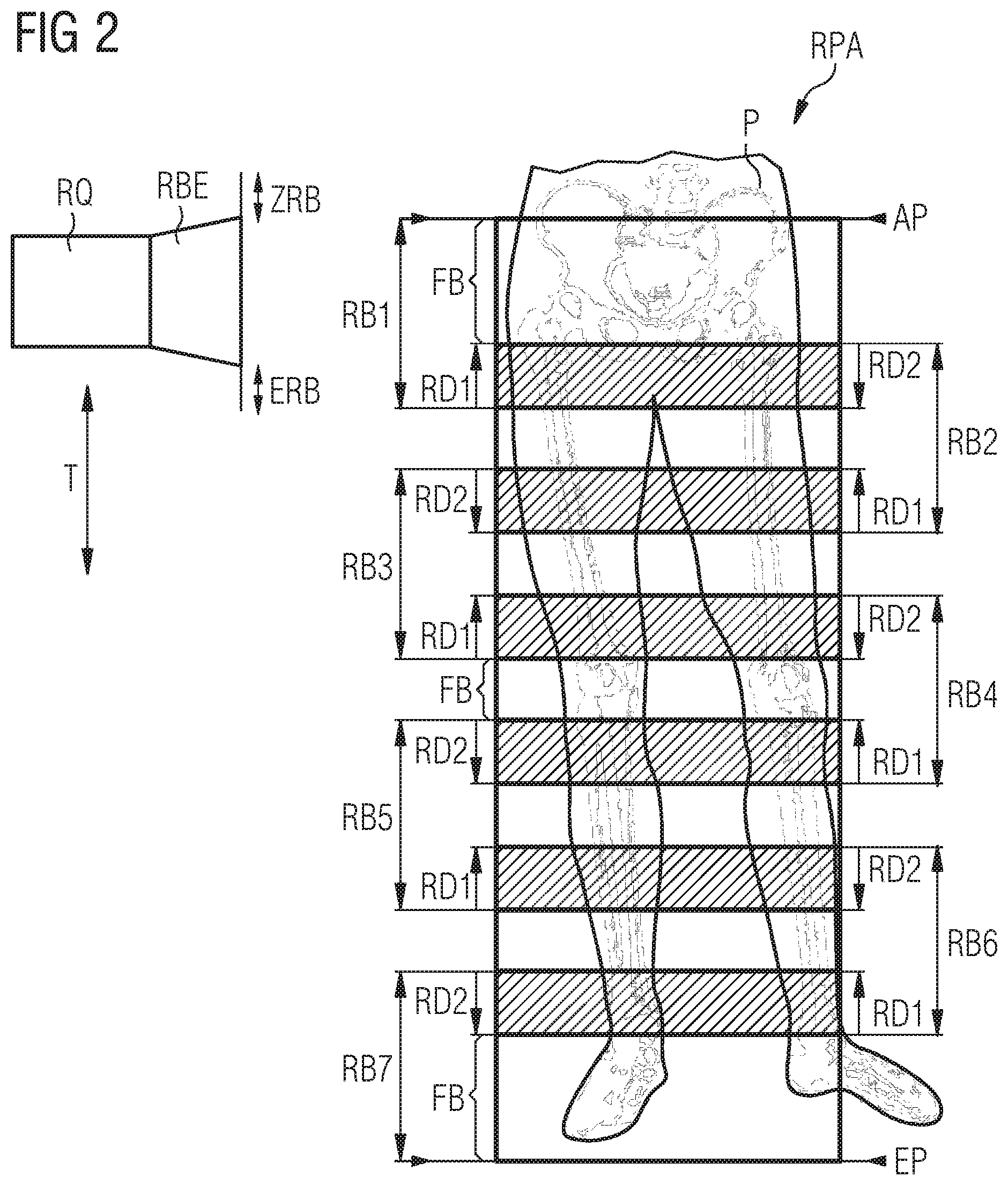
FIG. 2 shows a first embodiment variant for creating a panoramic x-ray recording RPA. The x-ray source RQ is moved along a trajectory T. The objective here is to capture the hip and legs of the patient P with this panoramic x-ray recording RPA. The beginning of the panoramic x-ray recording RPA is marked with a first boundary line AP on the upper edge of the hip and the end of the panoramic x-ray recording RPA with a second boundary line EP below the ankle joint. For the sake of clarity, only the x-ray source RQ and an x-ray screen unit RBE arranged downstream of the x-ray source RQ is indicated here. At the exit of the x-ray screen unit RBE, a first semi-transparent x-ray screen ERB and a second semi-transparent x-ray screen ZRB in the screen opening of the x-ray screen unit RBE, depending on the requirement, can be moved into the x-ray beam cone RK output by the x-ray source RQ. How far the first semi-transparent x-ray screen and the second semi-transparent x-ray screen ERB, ZRB, in each case, is pushed or moved into the partial x-ray images RB1, . . . , RBn to be created can be predetermined before beginning the panoramic x-ray recording RPA by specifying a first overlapping area RD1 and a second overlapping area RD2. If for instance a partial x-ray image RB1 representing the hip area of the patient is begun, the first semi-transparent x-ray screen ERB in the x-ray screen unit RBE is moved into the x-ray beam cone RK by the x-ray source RQ after the size of a first overlapping area RD1 has been predetermined. For a second partial x-ray image RB2, the x-ray source RQ is moved accordingly along the trajectory T. During the movement of the x-ray source RQ, the second semi-transparent x-ray screen ZRB is moved into the opening of the x-ray screen unit RBE. The second partial x-ray image RB2 begins where the first overlapping area RD1 in the first partial x-ray image RB1 begins. Contrary to the first partial x-ray image RB1, the second partial x-ray image RB2 has a first overlapping area RD1 and a second overlapping area RD2. Within these first and second overlapping areas RD1, RD2, the x-ray dose of the x-ray beams directed at the patient P is reduced in accordance with the semi-transparent x-ray screens ERB, ZRB used. The width of the second overlapping area RD2 generated by the second semi-transparent x-ray screen ZRB in the second partial x-ray image RB2 corresponds to the width of the first overlapping area RD1 in the first partial x-ray image RB1 recorded with a reduced x-ray dose. Subsequent partial x-ray images RB3, . . . RBn-1 are created in the same way. The area between the first and second transition area RD1, RD2 in the partial x-ray images is x-rayed in each case with an x-ray dose optimized to the respective object section. The creation of further overlapping partial x-ray images RBn for the panoramic x-ray recording RPA is continued up to the second boundary line EP. However, with the last partial x-ray image RB7 for the panoramic x-ray recording RPA, the first semi-transparent x-ray screen ERB is moved out of the x-ray screen unit RBE, since only one more overlapping area for the preceding partial x-ray image RB6 is required. In the overall image a panoramic x-ray recording RPA, which could be created in the form of strips, is produced. This panoramic x-ray recording RPA then has areas with a high-contrast representation between the respectively overlapping first and second overlapping areas RD1, RD2. The partial x-ray images RB2, RB3, RB5 and RB6 in which neither hip joints, knee or ankle joints are represented can be created using a lower x-ray dose. This composition of the panoramic x-ray recording RPA is advantageous in that at least areas near the leg, such as for instance the socket of the pelvis, the knee and the ankle joint of the foot, were defined as focus areas FB and are represented with optimized x-ray radiation in the partial x-ray images RB1, RB4 and RB7. The long bones in between are of less importance in terms of assessing or establishing a leg axis for instance. In these sections, the patient P is only exposed here to a reduced x-ray dose.
FIG. 3 shows a further exemplary embodiment for assembling a first, second and third partial x-ray image RBn-1, RBn, RBn+1 to form a panoramic x-ray recording RPA. In this exemplary embodiment, contrary to the exemplary embodiment under FIG. 2, larger overlapping areas OL are provided in each case for the partial x-ray images. These overlapping areas OL between two partial x-ray images have at least the width of the first and/or second areas RD1, RD2 generated by the first and second x-ray screens ERB, ZRB in the corresponding partial x-ray images. If an adjacent partial x-ray image RBx-1 is joined to a partial x-ray image RBx and/or RBn+1 to form a panoramic x-ray recording RPA, the overlapping areas OL between the partial x-ray images RBx-1, RBx and RBx+1 are placed one on top of the other. When assembling partial x-ray images RB1, RB2; RP2, RP3; . . . , RBn, RBn+1, in each case the overlapping area OL extends approximately as far as the center of the partial x-ray images for instance. A section of a partial x-ray image with an object-related x-ray irradiation and an area of the partial x-ray image in which the x-ray radiation was reduced by the use of a first semi-transparent x-ray screen ERB or a second semi-transparent x-ray screen ZRB, lie one on top of the other in the overlapping areas in each case. If the overlapping area OL between the second and third partial x-ray image RBn, RBn+1 is viewed for instance, a section with an optimized x-ray radiation from the second partial x-ray image RBn with the second area RD2, the third partial x-ray image RBn+1 and the first area RD1 from the second partial x-ray image RBn with a section of the third partial x-ray image RBn+1 lie one above the other. An alignment of the second and third partial x-ray image RBn, RBn+1 and an alignment of the first and second partial x-ray image RBn-1, RBn is carried out in each case with the aid of identical distinctive points or surface structures in the overlapping areas OL. On completion of the correlation between the respectively adjacent partial x-ray images RB1, . . . , RBn, the areas which were recorded with a reduced x-ray dose are separated from the respective partial x-ray images and the remaining parts of the partial x-ray images RBn-1, RBn, RBn+1 are joined in a transition-free manner with one another.
In a further embodiment variant, only one boundary area per partial x-ray image, for instance an area which was recorded through a first x-ray screen ERB with a reduced x-ray dose RD1, can be overlaid with a boundary area of an adjacent partial x-ray image.
The following is a summary list of reference numerals and the corresponding structure used in the above description of the invention:
TABLE-US-00001 T Trajectory RA X-ray system KA Camera RQ X-ray source RK X-ray beam cone RBE X-ray screen unit D Detector unit L Table, patient table P Patient BD Detector movement direction BL Table movement direction SRA X-ray system control unit S Control unit SL Table control unit SRQ X-ray source control unit SBE X-ray screen control unit SBD Detector control unit BR Image computer SE Joystick E Input unit TE Touchscreen unit, display RB1, . . . , RBn First, . . . , n.sup.th partial x-ray image (RBn - x, . . . , RBn, . . . , RBn + y) ERB First semi-transparent x-ray screen/collimator ZRB Second semi-transparent x-ray screen/collimator DA1, . . . , DAx Detector representations RPA Panoramic x-ray recording OL Overlapping area B Monitor unit, display AP First boundary line EP Second boundary line FB Focus areas RD1 First overlapping area RD2 Second overlapping area
* * * * *
D00000
D00001
D00002
D00003
XML
uspto.report is an independent third-party trademark research tool that is not affiliated, endorsed, or sponsored by the United States Patent and Trademark Office (USPTO) or any other governmental organization. The information provided by uspto.report is based on publicly available data at the time of writing and is intended for informational purposes only.
While we strive to provide accurate and up-to-date information, we do not guarantee the accuracy, completeness, reliability, or suitability of the information displayed on this site. The use of this site is at your own risk. Any reliance you place on such information is therefore strictly at your own risk.
All official trademark data, including owner information, should be verified by visiting the official USPTO website at www.uspto.gov. This site is not intended to replace professional legal advice and should not be used as a substitute for consulting with a legal professional who is knowledgeable about trademark law.