Heads-up display for use in underwater applications
Partridge , et al. February 16, 2
U.S. patent number 10,921,597 [Application Number 16/109,356] was granted by the patent office on 2021-02-16 for heads-up display for use in underwater applications. This patent grant is currently assigned to Shearwater Research Inc.. The grantee listed for this patent is Shearwater Research Inc.. Invention is credited to Mitchell Gordon Burton, Jefferson Cervantes, Tyler Coen, Bruce Gregory Partridge.
| United States Patent | 10,921,597 |
| Partridge , et al. | February 16, 2021 |
| **Please see images for: ( Certificate of Correction ) ** |
Heads-up display for use in underwater applications
Abstract
A heads-up display comprises a housing, a pressure sealed optical element disposed at a front end of the housing, and a dive computer disposed within the housing. The dive computer includes a display panel. There is a lens disposed in the housing between the infrared cut-off filter and the display panel.
| Inventors: | Partridge; Bruce Gregory (Richmond, CA), Coen; Tyler (Richmond, CA), Burton; Mitchell Gordon (Richmond, CA), Cervantes; Jefferson (Richmond, CA) | ||||||||||
|---|---|---|---|---|---|---|---|---|---|---|---|
| Applicant: |
|
||||||||||
| Assignee: | Shearwater Research Inc.
(Richmond, CA) |
||||||||||
| Family ID: | 69586068 | ||||||||||
| Appl. No.: | 16/109,356 | ||||||||||
| Filed: | August 22, 2018 |
Prior Publication Data
| Document Identifier | Publication Date | |
|---|---|---|
| US 20200064632 A1 | Feb 27, 2020 | |
| Current U.S. Class: | 1/1 |
| Current CPC Class: | G02B 7/002 (20130101); G02B 27/0172 (20130101); B63C 11/02 (20130101); B63C 11/12 (20130101); G02B 27/0176 (20130101); G02B 5/208 (20130101); G02B 13/18 (20130101); B63C 2011/021 (20130101); B63C 2011/121 (20130101); G02B 2027/0178 (20130101); G02B 2027/014 (20130101) |
| Current International Class: | G02B 27/01 (20060101); G02B 5/20 (20060101); G02B 13/18 (20060101); B63C 11/12 (20060101); B63C 11/02 (20060101) |
References Cited [Referenced By]
U.S. Patent Documents
| 3735382 | May 1973 | Soult |
| 4236546 | December 1980 | Manley et al. |
| 5301668 | April 1994 | Hales |
| 5526280 | June 1996 | Consadori et al. |
| 5539422 | July 1996 | Heacock et al. |
| 5886822 | March 1999 | Spitzer |
| 6032664 | March 2000 | Gray et al. |
| 6181644 | January 2001 | Gallagher |
| 6204975 | March 2001 | Watters et al. |
| 6401714 | June 2002 | Giorgini |
| 6519548 | February 2003 | Kuroda et al. |
| 6671100 | December 2003 | McRuer |
| 6856578 | February 2005 | Magine et al. |
| 6868360 | March 2005 | Olstad et al. |
| 7038639 | May 2006 | Olstad et al. |
| 7628153 | December 2009 | Juergensen |
| 7639208 | December 2009 | Ha et al. |
| 7927558 | April 2011 | Kirollos et al. |
| 8028696 | October 2011 | Juergensen |
| 8159751 | April 2012 | Martins |
| 9104024 | August 2015 | Partridge et al. |
| 9908599 | March 2018 | Zulonas et al. |
| 2004/0046710 | March 2004 | Adams et al. |
| 2005/0183721 | August 2005 | Juergensen |
| 2005/0217676 | October 2005 | Parker |
| 2007/0215157 | September 2007 | Straw |
| 2008/0106489 | May 2008 | Brown |
| 2009/0126482 | May 2009 | Fundak et al. |
| 2009/0161225 | June 2009 | Liu |
| 2010/0254017 | October 2010 | Martins |
| 2012/0132207 | May 2012 | Straw |
| 2012/0235902 | September 2012 | Eisenhardt et al. |
| 2013/0044043 | February 2013 | Abdollahi et al. |
| 2013/0222213 | August 2013 | Abdollahi et al. |
| 2013/0222235 | August 2013 | Abdollahi et al. |
| 2013/0257621 | October 2013 | Juergensen |
| 2010076177 | Jul 2010 | WO | |||
| 2012035021 | Mar 2012 | WO | |||
Other References
|
Open Safety. Apocalypse Type IV Rebreather User Manual. copyright 2009. cited by applicant. |
Primary Examiner: Tallman; Robert E.
Attorney, Agent or Firm: Oyen Wiggs Green & Mutala LLP Garner; Nicholas
Claims
What is claimed is:
1. A heads-up display comprising: a housing having a front housing portion and a rear housing portion to which the front housing portion thereof couples via a rear end of the front housing portion thereof; a pressure sealed optical element disposed at a front end of the front housing portion of the housing; a dive computer disposed within the rear housing portion of the housing, the dive computer including a display panel; and a lens disposed in the housing between the pressure sealed optical element and the display panel.
2. The heads-up display as claimed in claim 1 wherein the lens is an aspheric lens.
3. The heads-up display as claimed in claim 1 wherein the pressure sealed optical element is an infrared cut-off filter.
4. The heads-up display as claimed in claim 1 wherein the housing is waterproof.
5. The heads-up display as claimed in claim 1 wherein the housing is configured to be releasably retained by a mount.
6. The heads-up display as claimed in claim 1 further including a battery which powers the dive computer.
7. In combination, a heads-up display, and an articulated mount which allows positioning of the heads-up display to be adjusted, and the heads-up display comprising: a housing to which the mount couples; a pressure sealed optical element disposed at a front end of the housing; a dive computer disposed within the housing, the dive computer including a display panel; and a lens disposed in the housing between the pressure sealed optical element and the display panel.
8. The heads-up display as claimed in claim 1 wherein the housing is substantially cylindrical.
9. The heads-up display as claimed in claim 1 further including an O-ring which seals the rear housing portion and the front housing portion when the housing is assembled.
10. The heads-up display as claimed in claim 1 wherein the front housing portion and the rear housing portion of the housing threadably couple together.
11. Use of the heads-up display as claimed in claim 1 for underwater applications.
12. In combination, the heads-up display as claimed in claim 1 and a mount which allows positioning of the heads-up display to be adjusted.
13. In combination, the heads-up display as claimed in claim 1 and a mount configured to couple the heads-up display to a regulator.
14. In combination, the heads-up display as claimed in claim 1 and a mount configured to couple the heads-up display to a second stage hose fitting of a regulator.
15. In combination, the heads-up display as claimed in claim 1 and a mount configured to couple the heads-up display to a helmet.
16. In combination, the heads-up display as claimed in claim 1 and a mount configured to couple the heads-up display to a scuba mask.
17. The combination as claimed in claim 16 wherein the mount spaces the housing from the scuba mask.
18. The heads-up display as claimed in claim 1 wherein the pressure sealed optical element, the display panel and the lens align along a common axis.
19. The combination as claimed in claim 7, wherein the waterproof housing is releasably retained by the mount.
20. In combination, a heads-up display, and a mount which allows positioning of the heads-up display to be adjusted, the mount including a collar which releasably retains the heads-up display and a clamp which releasably clamps the mount in position, and the heads-up display comprising: a housing to which the mount couples; a pressure sealed optical element disposed at a front end of the housing; a dive computer disposed within the housing, the dive computer including a display panel; and a lens disposed in the housing between the pressure sealed optical element and the display panel.
Description
BACKGROUND OF THE INVENTION
Field of the Invention
The present invention relates to a heads-up display for use in underwater applications and, in particular, to a heads-up display with an aspheric lens for use in underwater applications.
Description of the Related Art
It is known to provide a heads-up display for underwater applications. For example, U.S. Pat. No. 9,104,024 which issued on Aug. 11, 2015, to Partridge et al. discloses a heads-up display comprising a housing and a display panel disposed within the housing. There is also an objective lens and an achromatic lens is disposed within the housing. The achromatic lens is disposed within the housing between the display panel and the objective lens. Information on the display panel is visible by a user looking through the objective lens and the achromatic lens. The heads-up display is coupled to a rebreather and may be coupled the rebreather by an articulate mounting arm.
SUMMARY OF THE INVENTION
There is provided a heads-up display comprising a housing, a pressure sealed optical element disposed at a front end of the housing, and a dive computer disposed within the housing. The dive computer includes a display panel. There is a lens disposed in the housing between the infrared cut-off filter and the display panel. The lens may be an aspheric lens. The pressure sealed optical element may be an infrared cut-off filter. The housing may be waterproof. The housing may be configured to be releaseably retained by a mount. The heads-up display may further include a battery which powers the dive computer.
BRIEF DESCRIPTIONS OF DRAWINGS
The invention will be more readily understood from the following description of the embodiments thereof given, by way of example only, with reference to the accompanying drawings, in which:
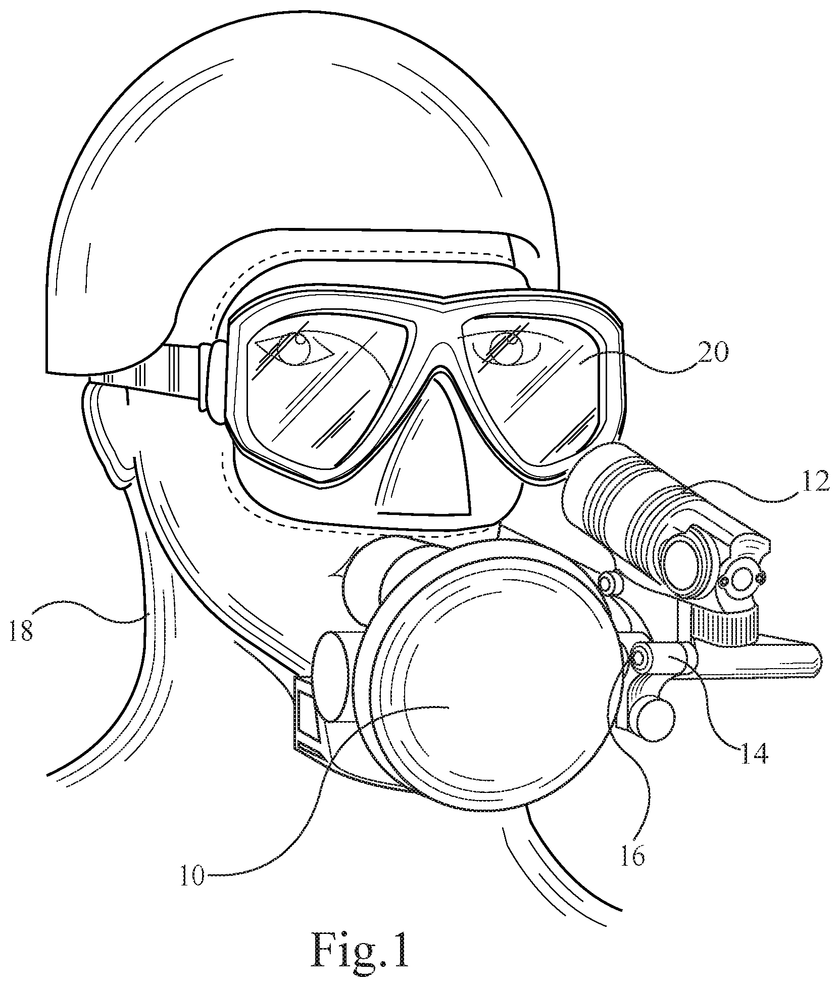
FIG. 1 is a perspective view of a heads-up display mounted on a regulator and worn by a user;
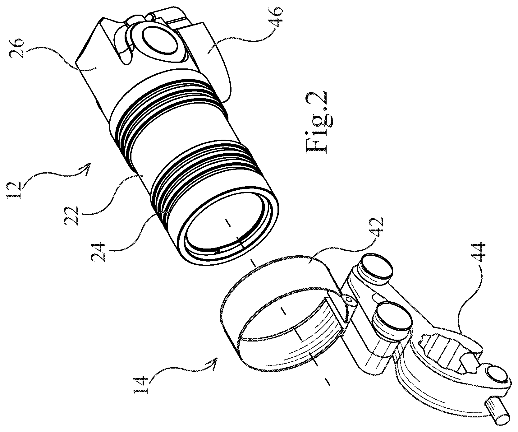
FIG. 2 is a perspective view of the heads-up display shown in FIG. 1;
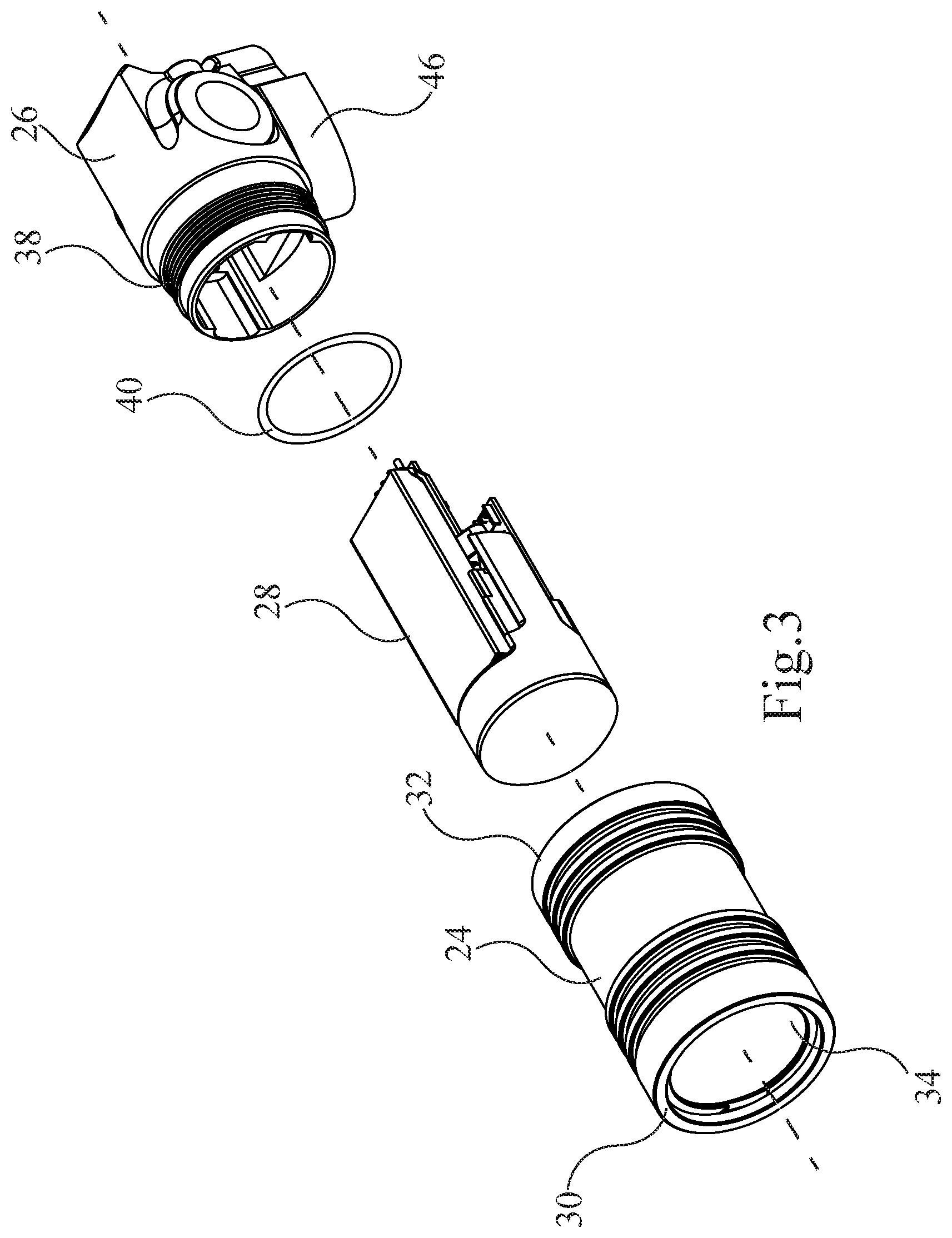
FIG. 3 is an exploded view of the heads-up display shown in FIG. 2;
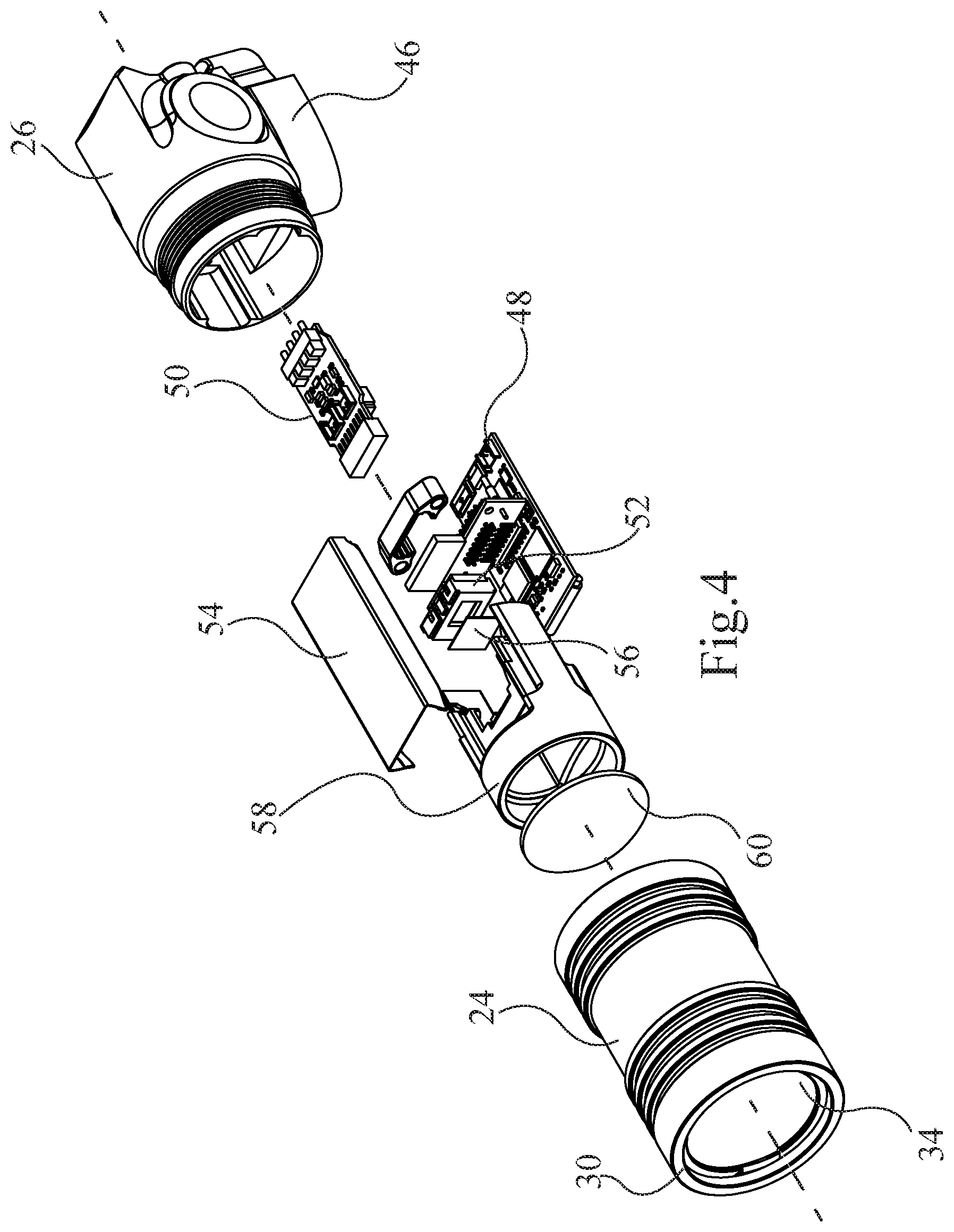
FIG. 4 is another exploded view of the heads-up display shown in FIG. 2;
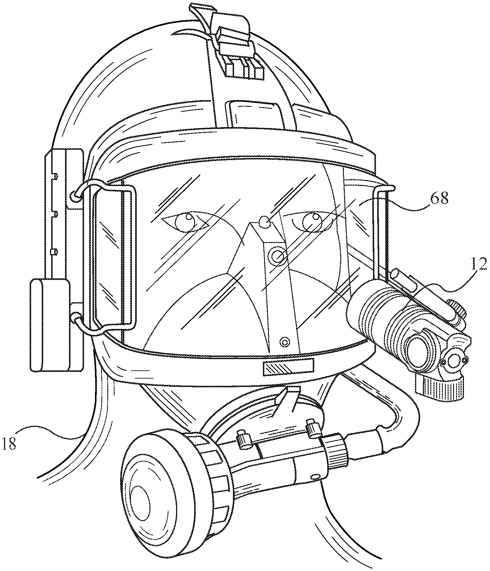
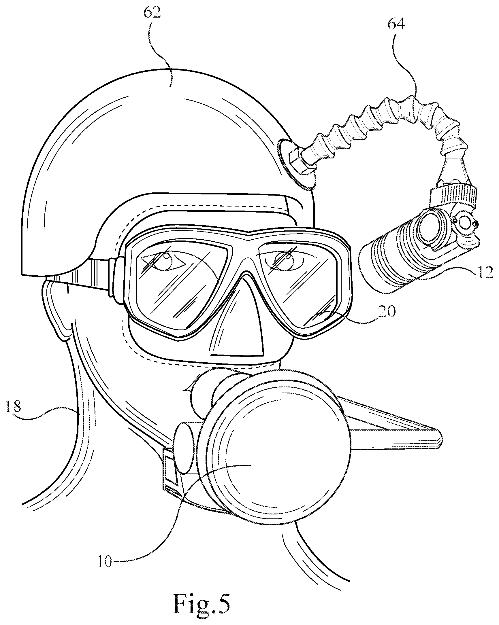
FIG. 5 is a perspective of the heads-up display shown in FIG. 2 mounted on a helmet and worn by a user;
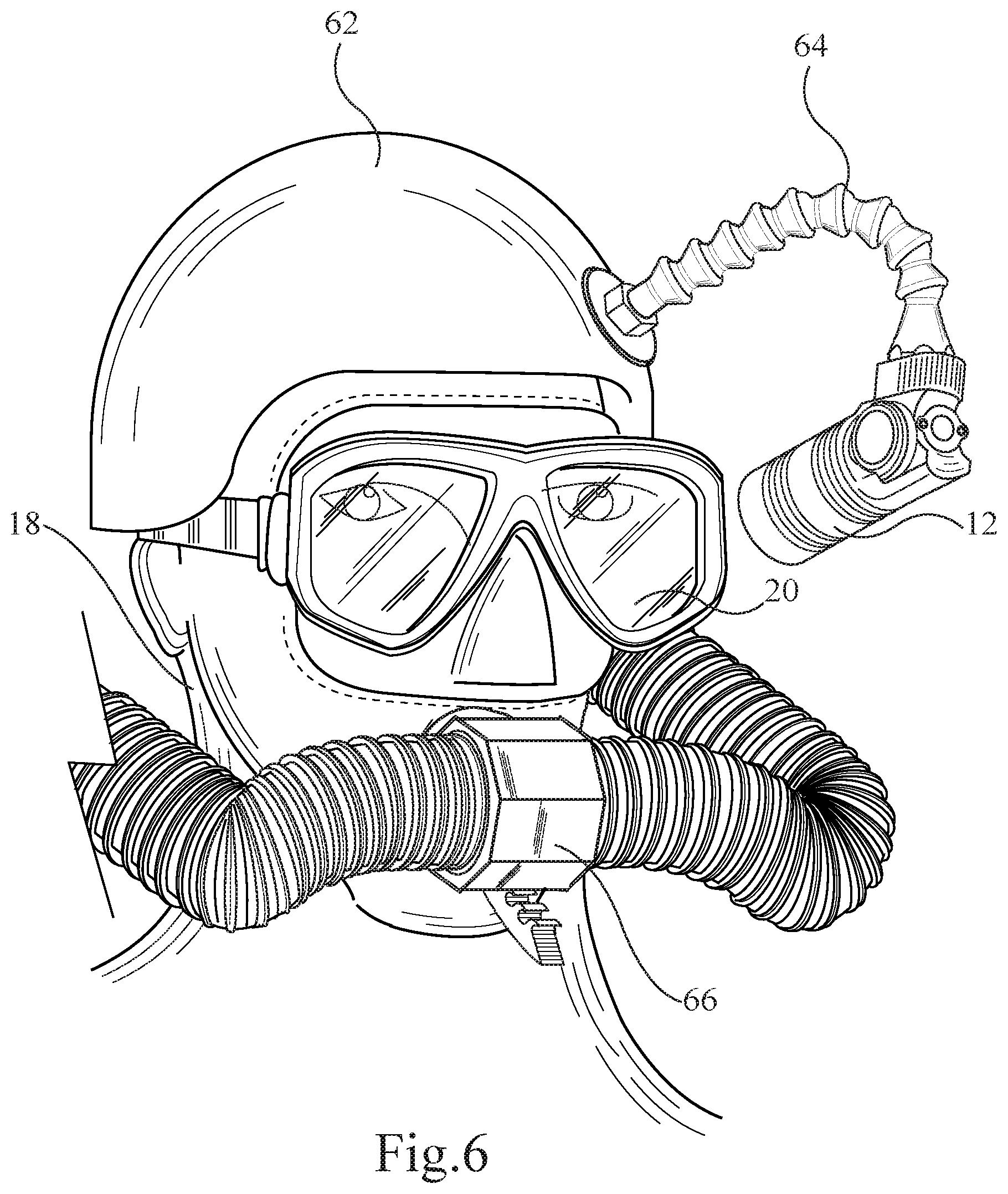
FIG. 6 is a perspective of the heads-up display shown in FIG. 2 mounted on a rebreather and worn by a user; and
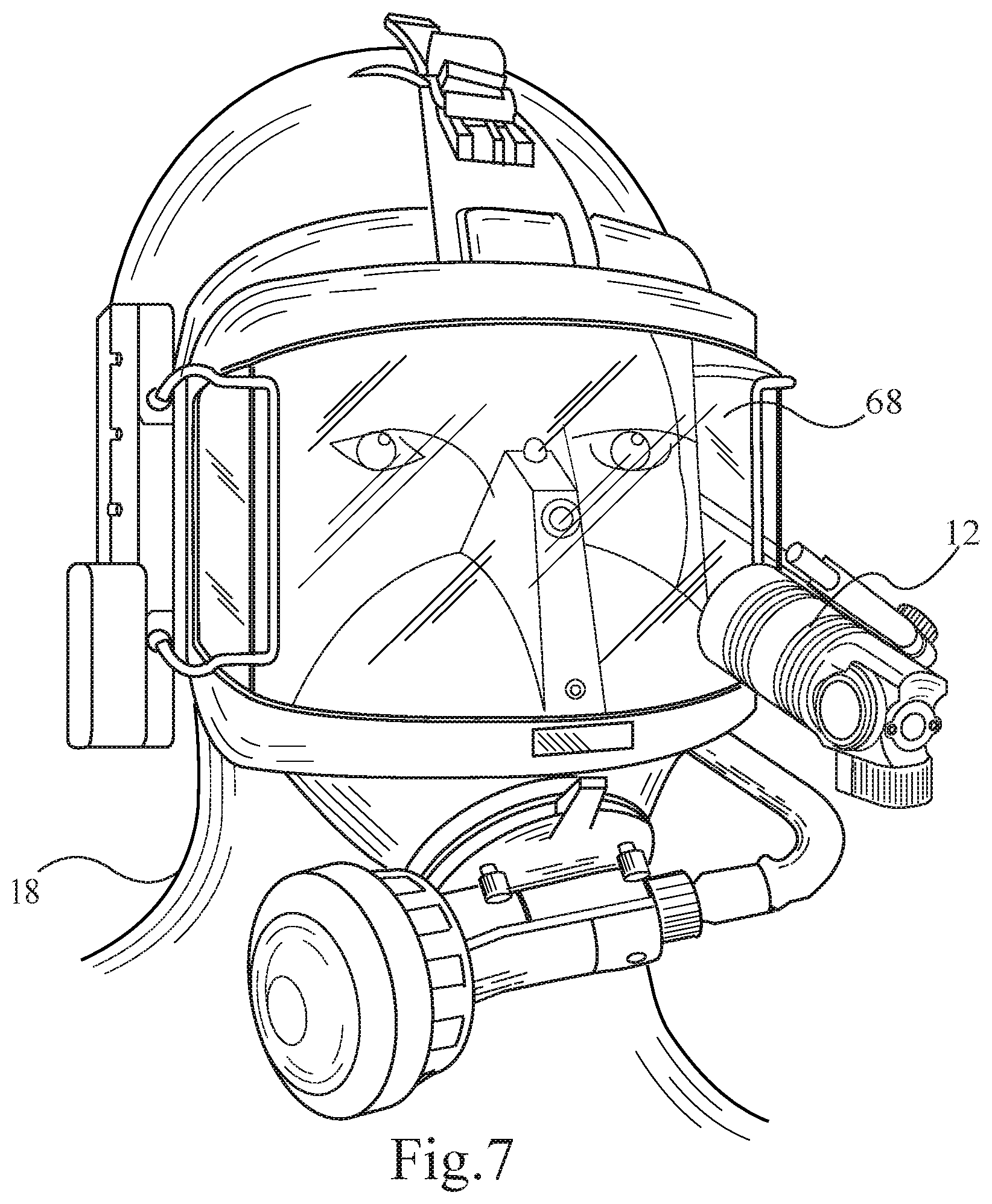
FIG. 7 is a perspective of the heads-up display shown in FIG. 2 mounted on a scuba mask worn by a user.
DESCRIPTIONS OF THE PREFERRED EMBODIMENTS
Referring to the drawings and first to FIG. 1, a regulator 10 is shown in fragment. The regulator 10 is a conventional regulator commonly used by divers and is accordingly not described in detail herein. There is an improved heads-up display 12 coupled to the regulator 10 by a mount 14. In this example, the heads-up display is mounted to a second stage hose fitting 16 of the regulator 10. The mount 14 may be an articulated mount to allow a user 18 to adjust a position of the heads-up display 12 in order to place the heads-up display 12 in a line of sight of the user 18 through goggles 20.
The heads-up display 12 and the mount 14 are shown in greater detail in FIG. 2. The heads-up display 12 generally comprises a waterproof housing 22 having a front housing portion 24 and a rear housing portion 26 which, as shown in FIG. 3, house a dive computer 28. In this example, the front housing portion 24 is substantially cylindrical and has a front end 30 and rear end 32. There is a pressure sealed optical element 34 at the front end 30 of the front housing portion 24 and there is internal threading (not shown) at the rear end 32 of the front housing portion 24. The pressure sealed optical element 34 is an infrared cut-off filter, in this example, but the pressure sealed optical element may be any type of pressure sealed optical element 34 suitable for a heads-up display. There is an O-ring 40 which seals the rear housing portion 26 and the front housing portion 24 when the housing 22 is assembled. Referring back to FIG. 2, the mount 14 generally comprises a collar 42, which releaseably retains the heads-up display 12, and a clamp 44 which releaseably clamps to the mount 14 in position. The heads-up display 12 may also be provided with mounting holes, for example mounting hole 46, to allow for custom mounting. The heads-up display 12 is a stand-alone heads-up display.
The dive computer 28 is shown in greater detail in FIG. 4. There is a main printed circuit board assembly 48 and a daughter printed circuit board assembly 50. There is a display panel 52 mounted on the main printed circuit board assembly 48. The display panel 52 is an LCD display panel, in the example, but the display panel may be any type of display panel suitable for a heads-up display. There is also a battery 54 which powers the dive computer 28. A polarizing filter 56 overlays the display panel 52 and there is a lens spacer 58 which spaces-apart the display panel 52 and a lens 60. The lens 60 is an aspheric lens, in this example, but the lens may be any type of lens suitable for a heads-up display. The lens 60 is disposed between the display panel 52 and the infrared cut-off filter 34. Information on the display panel 52 is visible by the user 18 looking through the infrared cut-off filter 34 and the lens 60.
FIG. 5 shows the heads-up display 12 custom mounted on a helmet 62 worn by the user 18. In this example, the heads-up display is mounted on the helmet 62 using an articulated mounting arm 64. FIG. 6 shows the heads-up display 12 custom mounted on a helmet 64 worn by the user 18 wearing a rebreather 66. FIG. 7 shows the heads-up display 12 custom mounted on a scuba mask 68 worn by the user 18. It will be understood by a person skilled in the art that the heads-up display 12 may be custom mounted in other manners.
It will also be understood by a person skilled in the art that many of the details provided above are by way of example only, and are not intended to limit the scope of the invention which is to be determined with reference to the following claims.
* * * * *
D00000
D00001
D00002
D00003
D00004
D00005
D00006
D00007
XML
uspto.report is an independent third-party trademark research tool that is not affiliated, endorsed, or sponsored by the United States Patent and Trademark Office (USPTO) or any other governmental organization. The information provided by uspto.report is based on publicly available data at the time of writing and is intended for informational purposes only.
While we strive to provide accurate and up-to-date information, we do not guarantee the accuracy, completeness, reliability, or suitability of the information displayed on this site. The use of this site is at your own risk. Any reliance you place on such information is therefore strictly at your own risk.
All official trademark data, including owner information, should be verified by visiting the official USPTO website at www.uspto.gov. This site is not intended to replace professional legal advice and should not be used as a substitute for consulting with a legal professional who is knowledgeable about trademark law.