Optical imaging lens assembly
Hu , et al. February 16, 2
U.S. patent number 10,921,560 [Application Number 16/224,685] was granted by the patent office on 2021-02-16 for optical imaging lens assembly. This patent grant is currently assigned to ZHEJIANG SUNNY OPTICAL CO., LTD. The grantee listed for this patent is Zhejiang Sunny Optical Co., Ltd. Invention is credited to Yabin Hu, Bo Song, Kaiyuan Zhang.


View All Diagrams
| United States Patent | 10,921,560 |
| Hu , et al. | February 16, 2021 |
Optical imaging lens assembly
Abstract
An optical imaging lens assembly is disclosed. The optical imaging lens assembly includes, sequentially along an optical axis from an object side to an image side, a first lens to a fifth lens. The first lens may have a positive refractive power and a concave object-side surface. The second lens may have a positive or a negative refractive power and a concave object-side surface. The third lens may have a positive or a negative refractive power. The fourth lens may have a positive refractive power and a convex image-side surface. The fifth lens may have a negative refractive power, and an object-side surface of the fifth lens and an image-side surface of the fifth lens may both be concave surfaces. A center thickness CT3 of the third lens on the optical axis and a center thickness CT4 of the fourth lens on the optical axis satisfy: CT3/CT4.gtoreq.1.5.
| Inventors: | Hu; Yabin (Ningbo, CN), Zhang; Kaiyuan (Ningbo, CN), Song; Bo (Ningbo, CN) | ||||||||||
|---|---|---|---|---|---|---|---|---|---|---|---|
| Applicant: |
|
||||||||||
| Assignee: | ZHEJIANG SUNNY OPTICAL CO., LTD
(Ningbo, CN) |
||||||||||
| Family ID: | 65439331 | ||||||||||
| Appl. No.: | 16/224,685 | ||||||||||
| Filed: | December 18, 2018 |
Prior Publication Data
| Document Identifier | Publication Date | |
|---|---|---|
| US 20190121096 A1 | Apr 25, 2019 | |
Related U.S. Patent Documents
| Application Number | Filing Date | Patent Number | Issue Date | ||
|---|---|---|---|---|---|
| PCT/CN2018/079778 | Mar 21, 2018 | ||||
Foreign Application Priority Data
| Aug 21, 2017 [CN] | 2017 1 0719642 | |||
| Aug 21, 2017 [CN] | 2017 2 1047412 U | |||
| Current U.S. Class: | 1/1 |
| Current CPC Class: | G02B 13/0045 (20130101); G02B 9/60 (20130101); G02B 13/04 (20130101); G02B 13/06 (20130101) |
| Current International Class: | G02B 13/00 (20060101); G02B 9/60 (20060101); G02B 13/06 (20060101); G02B 13/04 (20060101) |
| Field of Search: | ;359/763,764,767,714,713 |
References Cited [Referenced By]
U.S. Patent Documents
| 2013/0308209 | November 2013 | Baba |
| 2015/0062724 | March 2015 | Yu et al. |
| 2015/0098011 | April 2015 | Huang |
| 2015/0370038 | December 2015 | Sun |
| 2016/0097916 | April 2016 | Tang |
| 2017/0023770 | January 2017 | Teraoka |
| 106980171 | Jul 2017 | CN | |||
| 106990508 | Jul 2017 | CN | |||
| 107290843 | Oct 2017 | CN | |||
| 207037206 | Feb 2018 | CN | |||
Attorney, Agent or Firm: Hauptman Ham, LLP
Parent Case Text
CROSS-REFERENCE TO RELATED APPLICATIONS
This application is a continuation of International Application. No. PCT/CN2018/079778, filed on Mar. 21, 2018, which claims the priorities and rights to Chinese Patent Application No. 201710719642.0 and Chinese Patent Application No. 201721047412.6 filed with the China National Intellectual Property Administration (CNIPA) on Aug. 21, 2017. All of the aforementioned applications are hereby incorporated by reference in their entireties.
Claims
What is claimed is:
1. An optical imaging lens assembly comprising, sequentially along an optical axis from an object side to an image side, a first lens, a second lens, a third lens, a fourth lens, and a fifth lens, wherein the first lens has a positive refractive power, and an object-side surface of the first lens is a convex surface; the second lens has a positive refractive power or a negative refractive power, and an object-side surface of the second lens is a concave surface; the third lens has a positive refractive power or a negative refractive power; the fourth lens has a positive refractive power, and an image-side surface of the fourth lens is a convex surface; the fifth lens has a negative refractive power, and an object-side surface of the fifth lens and an image-side surface of the fifth lens are concave surfaces; a center thickness CT3 of the third lens on the optical axis and a center thickness CT4 of the fourth lens on the optical axis satisfy: CT3/CT4.gtoreq.1.5; and a radius of curvature R9 of the object-side surface of the fifth lens and a center thickness CT5 of the fifth lens on the optical axis satisfy: -7<R9/CT5.ltoreq.-5.
2. The optical imaging lens assembly according to claim 1, wherein half of a maximal field-of-view HFOV of the optical imaging lens assembly satisfies: HFOV.gtoreq.45.degree..
3. The optical imaging lens assembly according to claim 1, wherein the radius of curvature R9 of the object-side surface of the fifth lens and a radius of curvature R10 of the image-side surface of the fifth lens satisfy: -0.9<R10/R9<-0.7.
4. The optical imaging lens assembly according to claim 1, wherein an effective focal length f1 of the first lens and a center thickness CT1 of the first lens on the optical axis satisfy: 8.0<f1/CT1<11.0.
5. The optical imaging lens assembly according to claim 4, wherein the effective focal length f1 of the first lens and a radius of curvature R1 of the object-side surface of the first lens satisfy: 1.0<f1/R1<4.0.
6. The optical imaging lens assembly according to claim 1, wherein an effective focal length f of the optical imaging lens assembly and an effective focal length f4 of the fourth lens satisfy: 0.6.ltoreq.f4/f<0.8.
7. The optical imaging lens assembly according to claim 6, wherein the effective focal length f4 of the fourth lens and the center thickness CT4 of the fourth lens on the optical axis satisfy: 4.0<f4/CT4<5.0.
8. The optical imaging lens assembly according to claim 7, wherein the effective focal length f4 of the fourth lens and an effective focal length f5 of the fifth lens satisfy: -1.6<f4/f5<-1.4.
9. The optical imaging lens assembly according to claim 1, wherein a radius of curvature R5 of an object-side surface of the third lens and a radius of curvature R6 of an image-side surface of the third lens satisfy: 0<|R6/R5|<0.5.
10. An optical imaging lens assembly comprising, sequentially along an optical axis from an object side to an image side, a first lens, a second lens, a third lens, a fourth lens, and a fifth lens, wherein each of the first lens and the fourth lens has a positive refractive power; at least one of the second lens, the third lens, or the fifth lens has a negative refractive power; half of a maximal field-of-view HFOV of the optical imaging lens assembly satisfies: HFOV.gtoreq.45.degree.; a center thickness CT3 of the third lens on the optical axis and a center thickness CT4 of the fourth lens on the optical axis satisfy: CT3/CT4.gtoreq.1.5; and a radius of curvature R9 of an object-side surface of the fifth lens and a center thickness CT5 of the fifth lens on the optical axis satisfy: -7<R9/CT5.ltoreq.-5.
11. The optical imaging lens assembly according to claim 10, wherein the radius of curvature R9 of the object-side surface of the fifth lens and a radius of curvature R10 of an image-side surface of the fifth lens satisfy: -0.9<R10/R9<-0.7.
12. The optical imaging lens assembly according to claim 10, wherein an effective focal length f1 of the first lens and a center thickness CT1 of the first lens on the optical axis satisfy: 8.0<f1/CT1<11.0.
13. The optical imaging lens assembly according to claim 12, wherein the effective focal length f1 of the first lens and a radius of curvature R1 of an object-side surface of the first lens satisfy: 1.0<f1/R1<4.0.
14. The optical imaging lens assembly according to claim 12, wherein an effective focal length f of the optical imaging lens assembly and an effective focal length f4 of the fourth lens satisfy: 0.6.ltoreq.f4/f<0.8.
15. The optical imaging lens assembly according to claim 14, wherein the effective focal length f4 of the fourth lens and the center thickness CT4 of the fourth lens on the optical axis satisfy: 4.0<f4/CT4<5.0.
16. The optical imaging lens assembly according to claim 15, wherein the effective focal length f4 of the fourth lens and an effective focal length f5 of the fifth lens satisfy: -1.6<f4/f5<-1.4.
Description
TECHNICAL FIELD
The present disclosure relates to an optical imaging lens assembly, and more specifically to an optical imaging lens assembly including five lenses.
BACKGROUND
With an increasing demand of miniaturized electronic products such as cellphones and tablet computers on imaging functions, higher requirements on hardware of image sensors such as charge-coupled devices (CCD) or complementary metal-oxide semiconductor elements (CMOS) and optical performances of imaging lens assemblies have been brought forward. In the situation where the sizes of the image planes of the sensors are the same, the larger the field-of-view of the imaging lens assembly is, the more the number of captured images is. Moreover, the reduction of the sizes of the pixels of the sensor would weaken the capability of an optical system to collect light. Accordingly, the imaging lens assembly needs to have a larger field-of-view and a large aperture, so as to further improve shooting performances. Meanwhile, when the imaging requirements are satisfied, the less the number of lenses in an optical lens assembly is and the shorter the total track length of the optical lens assembly is, the more conductive to the development of tendency of miniaturization of electronic products is.
Therefore, the present disclosure is intended to provide an ultra-thin optical system that may be applicable to portable electronic products and has a large field-of-view and a good imaging quality.
SUMMARY
Technical solutions provided by the present disclosure solve at least some of the above-mentioned technical problems.
According to an aspect, the present disclosure provides an optical imaging lens assembly having an effective focal length f and an entrance pupil diameter EPD. The optical imaging lens assembly includes, sequentially along an optical axis from an object side to an image side, a first lens, a second lens, a third lens, a fourth lens, and a fifth lens. The first lens may have a positive refractive power, and an object-side surface of the first lens may be a convex surface. The second lens may have a positive refractive power or a negative refractive power, and an object-side surface of the second lens may be a concave surface. The third lens may have a positive refractive power or a negative refractive power. The fourth lens may have a positive refractive power, and an image-side surface of the fourth lens may be a convex surface. The fifth lens may have a negative refractive power, and an object-side surface of the fifth lens and an image-side surface of the fifth lens may both be concave surfaces. A center thickness CT3 of the third lens on the optical axis and a center thickness CT4 of the fourth lens on the optical axis satisfy: CT3/CT4.gtoreq.1.5.
According to another aspect, the present disclosure further provides an optical imaging lens assembly having an effective focal length f and an entrance pupil diameter EPD. The optical imaging lens assembly includes, sequentially along an optical axis from an object side to an image side, a first lens, a second lens, a third lens, a fourth lens, and a fifth lens. Each of the first lens and the fourth lens has a positive refractive power. At least one of the second lens, the third lens, or the fifth lens has a negative refractive power. Half of a maximal field-of-view HFOV of the optical imaging lens assembly satisfies: HFOV.gtoreq.45.degree.. A center thickness CT3 of the third lens on the optical axis and a center thickness CT4 of the fourth lens on the optical axis satisfy: CT3/CT4.gtoreq.1.5.
In an implementation, the half of the maximal field-of-view HFOV of the optical imaging lens assembly satisfies: HFOV.gtoreq.45.degree..
In an implementation, a radius of curvature R9 of an object-side surface of the fifth lens and a radius of curvature R10 of an image-side surface of the fifth lens may satisfy: -0.9<R10/R9<-0.7, for example, -0.85.ltoreq.R10/R9.ltoreq.-0.76.
In an implementation, the radius of curvature R9 of the object-side surface of the fifth lens and a center thickness CT5 of the fifth lens on the optical axis may satisfy: -7<R9/CT5.ltoreq.-5, for example, -6.04.ltoreq.R9/CT5.ltoreq.-5.03.
In an implementation, a maximum tilt angle .beta.52 of the image-side surface of the fifth lens may satisfy: 30.degree.<.beta.52<58.degree., for example, 30.6.degree..ltoreq..beta.52.ltoreq.57.degree..
In an implementation, an effective focal length f1 of the first lens and a center thickness CT1 of the first lens on the optical axis may satisfy: 8.0<f1/CT1<11.0, for example, 8.52.ltoreq.f1/CT1.ltoreq.10.66.
In an implementation, the effective focal length f1 of the first lens and a radius of curvature R1 of an object-side surface of the first lens may satisfy: 1.0<f1/R1<4.0, for example, 1.82.ltoreq.f1/R1.ltoreq.2.91.
In an implementation, the effective focal length f of the optical imaging lens assembly and an effective focal length f4 of the fourth lens may satisfy: 0.65.ltoreq.f4/f<0.8, for example, 0.70.ltoreq.f4/f.ltoreq.0.77.
In an implementation, the effective focal length f4 of the fourth lens and the center thickness CT4 of the fourth lens on the optical axis may satisfy: 4.0<f4/CT4<5.0, for example, 4.39.ltoreq.f4/CT4.ltoreq.4.71.
In an implementation, the effective focal length f4 of the fourth lens and an effective focal length f5 of the fifth lens may satisfy: -1.6<f4/f5<-1.4, for example, -1.54.ltoreq.f4/f5.ltoreq.-1.47.
In an implementation, a radius of curvature R5 of an object-side surface of the third lens and a radius of curvature R6 of an image-side surface of the third lens may satisfy: 0<|R6/R5|<0.5, for example, 0<|R6/R5|.ltoreq.0.25.
In an implementation, the object-side surface of the first lens is a convex surface.
In an implementation, an object-side surface of the second lens is a concave surface.
In an implementation, an image-side surface of the fourth lens is a convex surface.
In an implementation, the fifth lens has a negative refractive power, and the object-side surface of the fifth lens and the image-side surface of the fifth lens are concave surfaces.
The optical imaging lens assembly with the above configuration may further have at least one of the beneficial effects such as ultra-thin, large field-of-view, high resolution, miniaturization, high imaging quality, or balanced aberration.
BRIEF DESCRIPTION OF THE DRAWINGS
By describing non-limiting implementations below in detail with reference to the accompanying drawings, other features, objectives and advantages of the present disclosure will be more apparent. In the accompanying drawings:
FIG. 1 is a schematic structural diagram illustrating an optical imaging lens assembly according to Embodiment 1 of the present disclosure;
FIGS. 2A-2D respectively illustrate a longitudinal aberration curve, an astigmatic curve, a distortion curve, and a lateral color curve of the optical imaging lens assembly according to Embodiment 1;
FIG. 3 is a schematic structural diagram illustrating an optical imaging lens assembly according to Embodiment 2 of the present disclosure;
FIGS. 4A-4D respectively illustrate a longitudinal aberration curve, an astigmatic curve, a distortion curve, and a lateral color curve of the optical imaging lens assembly according to Embodiment 2;
FIG. 5 is a schematic structural diagram illustrating an optical imaging lens assembly according to Embodiment 3 of the present disclosure;
FIGS. 6A-6D respectively illustrate a longitudinal aberration curve, an astigmatic curve, a distortion curve, and a lateral color curve of the optical imaging lens assembly according to Embodiment 3;
FIG. 7 is a schematic structural diagram illustrating an optical imaging lens assembly according to Embodiment 4 of the present disclosure;
FIGS. 8A-8D respectively illustrate a longitudinal aberration curve, an astigmatic curve, a distortion curve, and a lateral color curve of the optical imaging lens assembly according to Embodiment 4;
FIG. 9 is a schematic structural diagram illustrating an optical imaging lens assembly according to Embodiment 5 of the present disclosure;
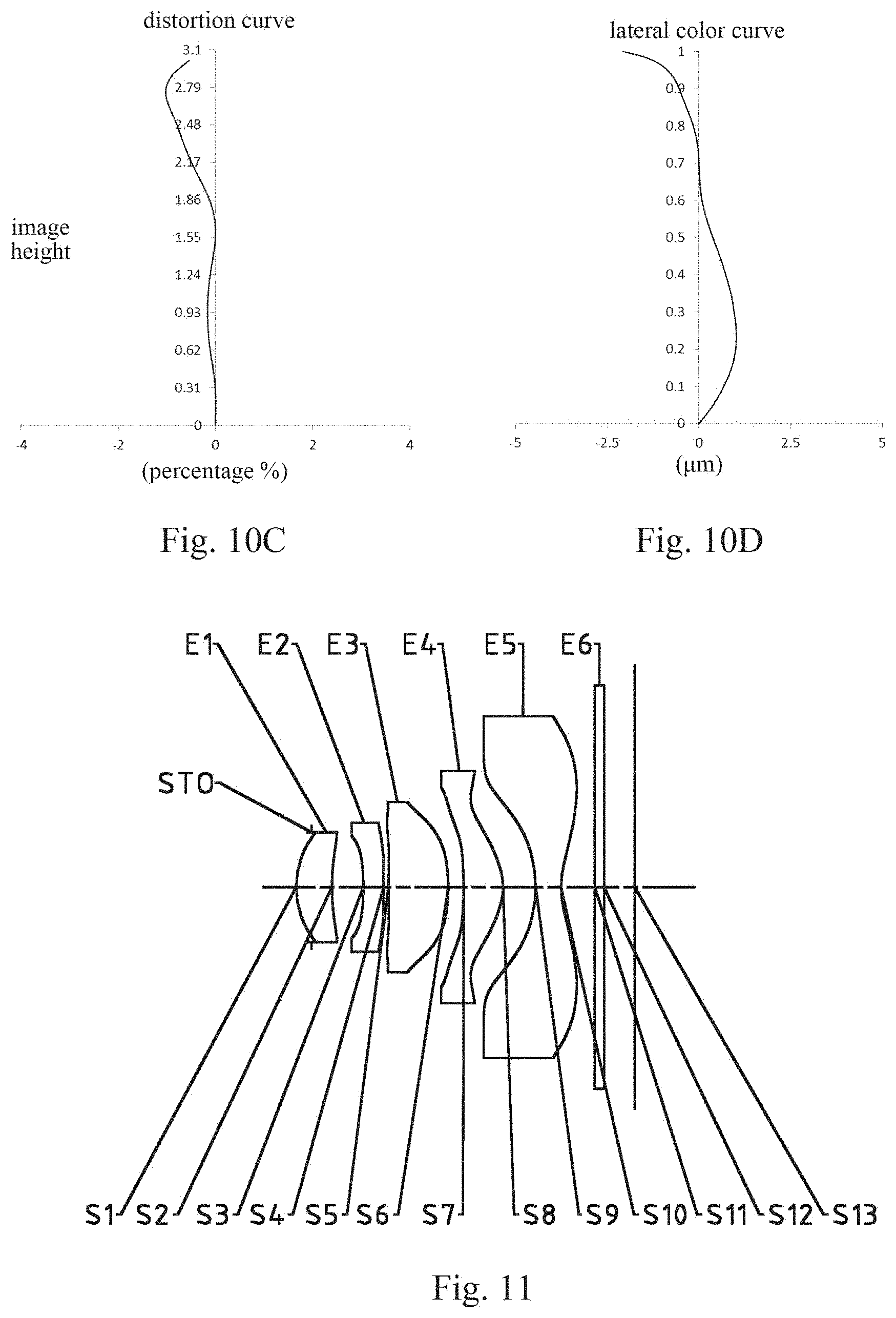
FIGS. 10A-10D respectively illustrate a longitudinal aberration curve, an astigmatic curve, a distortion curve, and a lateral color curve of the optical imaging lens assembly according to Embodiment 5;
FIG. 11 is a schematic structural diagram illustrating an optical imaging lens assembly according to Embodiment 6 of the present disclosure;
FIGS. 12A-12D respectively illustrate a longitudinal aberration curve, an astigmatic curve, a distortion curve, and a lateral color curve of the optical imaging lens assembly according to Embodiment 6;
FIG. 13 is a schematic structural diagram illustrating an optical imaging lens assembly according to Embodiment 7 of the present disclosure;
FIGS. 14A-14D respectively illustrate a longitudinal aberration curve, an astigmatic curve, a distortion curve, and a lateral color curve of the optical imaging lens assembly according to Embodiment 7;
FIG. 15 is a schematic structural diagram illustrating an optical imaging lens assembly according to Embodiment 8 of the present disclosure; and
FIGS. 16A-16D respectively illustrate a longitudinal aberration curve, an astigmatic curve, a distortion curve, and a lateral color curve of the optical imaging lens assembly according to Embodiment 8.
DETAILED DESCRIPTION
For a better understanding of the present disclosure, various aspects of the present disclosure will be described in more detail with reference to the accompanying drawings. It should be understood that the detailed description is merely an illustration for the exemplary implementations of the present disclosure rather than a limitation to the scope of the present disclosure in any way. Throughout the specification, the same reference numerals designate the same elements. The expression "and/or" includes any and all combinations of one or more of the associated listed items.
It should be noted that in the specification, the expressions, such as "first," and "second" are only used to distinguish one feature from another, rather than represent any limitations to the features. Thus, the first lens discussed below may also be referred to as the second lens without departing from the teachings of the present disclosure.
In the accompanying drawings, the thicknesses, sizes and shapes of the lenses have been slightly exaggerated for the convenience of explanation. Specifically, shapes of spherical surfaces or aspheric surfaces shown in the accompanying drawings are shown by examples. That is, the shapes of the spherical surfaces or the aspheric surfaces are not limited to the shapes of the spherical surfaces or the aspheric surfaces shown in the accompanying drawings. The accompanying drawings are merely illustrative and not strictly drawn to scale.
It should be further understood that the terms "comprising," "including," "having" and variants thereof, when used in the specification, specify the presence of stated features, elements and/or components, but do not exclude the presence or addition of one or more other features, elements, components and/or combinations thereof. In addition, expressions, such as "at least one of," when preceding a list of listed features, modify the entire list of features rather than an individual element in the list. Further, the use of "may," when describing the implementations of the present disclosure, relates to "one or more implementations of the present disclosure." Also, the term "exemplary" is intended to refer to an example or illustration.
As used herein, the terms "substantially," "about" and similar terms are used as a term of approximation and not as a term of degree, and are intended to account for the inherent deviations in measured or calculated values that would be recognized by those of ordinary skill in the art.
Unless otherwise defined, all terms (including technical and scientific terms) used herein have the same meaning as commonly understood by those of ordinary skill in the art to which the present disclosure belongs. It should be further understood that terms (i.e., those defined in commonly used dictionaries) should be interpreted as having a meaning that is consistent with their meaning in the context of the relevant art and will not be interpreted in an idealized or overly formal sense unless expressly so defined herein.
In addition, the paraxial area refers to an area near the optical axis. The first lens is the lens closest to the object, and the fifth lens is the lens closest to the photosensitive element. In this specification, the surface closest to the object in each lens is referred to as the object-side surface, and the surface closest to the image plane in each lens is referred to as the image-side surface.
It should also be noted that the embodiments in the present disclosure and the features in the embodiments may be combined with each other on a non-conflict basis. The present disclosure will be described below in detail with reference to the accompanying drawings and in combination with the embodiments.
The present disclosure is further described below in combination with the embodiments.
The optical imaging lens assembly according to exemplary implementations of the present disclosure includes, for example, five lenses (i.e., a first lens, a second lens, a third lens, a fourth lens, and a fifth lens). The five lenses are arranged in sequence along an optical axis from an object side to an image side.
In an exemplary implementation, the first lens may have a positive refractive power, and an object-side surface of the first lens is a convex surface. The second lens may have a positive refractive power or a negative refractive power, and an object-side surface of the second lens is a concave surface. The third lens may have a positive refractive power or a negative refractive power. The fourth lens may have a positive refractive power, and an image-side surface of the fourth lens is a convex surface. The fifth lens may have a negative refractive power, and an object-side surface of the fifth lens and an image-side surface of the fifth lens may both be concave surfaces. By properly controlling the distribution of the positive and negative refractive powers of the lenses, the low-order aberrations of a control system may be effectively balanced, which makes the optical imaging lens assembly obtain a good imaging quality. Moreover, the characteristics of ultra-thin and large aperture may also be achieved.
In an exemplary implementation, half of a maximal field-of-view HFOV of the optical imaging lens assembly satisfies: HFOV.gtoreq.45.degree.. By controlling the optical system to have the half of the maximal field-of-view greater than 45.degree. (i.e., the field-of-view greater than 90.degree.), a wider visual field of the system where an image is formed may be ensured.
In an exemplary implementation, a center thickness CT3 of the third lens on the optical axis and a center thickness CT4 of the fourth lens on the optical axis may satisfy: CT3/CT4.gtoreq.1.5. By controlling the ratio of the center thickness of the third lens on the optical axis to the center thickness of the fourth lens on the optical axis to be greater than 1.5, the distribution of the positive refractive powers of the two lenses is adjusted, so that the fourth lens undertakes more refractive powers. Such a configuration helps an incident ray of a large field-of-view to be finally converged on the image plane of the optical imaging lens assembly after passing through the lenses.
In an exemplary implementation, a radius of curvature R9 of the object-side surface of the fifth lens and a radius of curvature R10 of the image-side surface of the fifth lens may satisfy: -0.9<R10/R9<-0.7, and more specifically, may further satisfy: -0.85.ltoreq.R10/R9.ltoreq.-0.76. The radii of curvature of the object-side surface and image-side surface of the fifth lens are controlled within a proper range, which is conductive to effectively correcting tangential comatic aberrations of the system.
In an exemplary implementation, the radius of curvature R9 of the object-side surface of the fifth lens and a center thickness CT5 of the fifth lens on the optical axis may satisfy: -7<R9/CT5.ltoreq.-5, and more specifically, may further satisfy: -6.04.ltoreq.R9/CT5.ltoreq.-5.03. With this configuration, the distortion generated in the large field-of-view system may be balanced, and at the same time, the angles of the chief rays in the rays of each of the fields reaching the image plane is large. Thus, the system is matched with a sensor chip having a large chief ray angle.
In an exemplary implementation, a maximum tilt angle .beta.52 of the image-side surface of the fifth lens may satisfy: 30.degree.<.beta.52<58.degree., and more specifically, may further satisfy: 30.6.degree..ltoreq..beta.52.ltoreq.57.degree.. By controlling the maximum tilt angle of the image-side surface of the fifth lens, it may be avoided that the effect of coating the edge of the lens is unsatisfactory due to the excessively large tilt angle, which leads to poor technology capability of the system.
In an exemplary implementation, an effective focal length f1 of the first lens and a center thickness CT1 of the first lens on the optical axis may satisfy: 8.0<f1/CT1<11.0, and more specifically, may further satisfy: 8.52.ltoreq.f1/CT1.ltoreq.10.66. By reasonably balancing the ratio of the effective focal length of the first lens to the center thickness, it is conductive to correcting the aberration of the optical imaging system, and the feasibility of the shaping and processing technologies may be ensured at the same time.
In an exemplary implementation, the effective focal length f1 of the first lens and a radius of curvature R1 of the object-side surface of the first lens may satisfy: 1.0<f1/R1<4.0, and more specifically, may further satisfy: 1.82.ltoreq.f1/R1.ltoreq.2.91. With this configuration, the radius of curvature of the object-side surface of the first lens is controlled not to be too small in the situation where the first lens undertakes a part of the positive refractive power, thus reducing the risk of generating a ghost image due to the large tilt angle.
In an exemplary implementation, an effective focal length f of the optical imaging lens assembly and an effective focal length f4 of the fourth lens may satisfy: 0.6.ltoreq.f4/f<0.8, and more specifically, may further satisfy: 0.70.ltoreq.f4/f.ltoreq.0.77. With this configuration, when TTL is reduced, the influence of the aberration caused by the amount of deflection of light is controlled. At the same time, the incident angle of the light entering on the object-side surface of the fourth lens is reduced as much as possible, which is conductive to the transmittance of the light.
In an exemplary implementation, the effective focal length f4 of the fourth lens and the center thickness CT4 of the fourth lens on the optical axis may satisfy: 4.0<f4/CT4<5.0, and more specifically, may further satisfy: 4.39.ltoreq.f4/CT4.ltoreq.4.71. The center thickness of the lens may affect the value of the refractive power. By controlling the ratio of the focal length of the fourth lens to the center thickness within a certain range, it is conductive to correcting the distortion and astigmatism of the system, and may further avoid the problem of technology capability caused by the excessively large or small center thickness.
In an exemplary implementation, the effective focal length f4 of the fourth lens and an effective focal length f5 of the fifth lens may satisfy: -1.6<f4/f5<-1.4, and more specifically, may further satisfy: -1.54.ltoreq.f4/f5.ltoreq.-1.47. Through the reasonable allocation that one lens has a positive refractive power and the other lens has a negative refractive power, it is conductive to balancing the chromatic aberration generated by the system.
In an exemplary implementation, a radius of curvature R5 of an object-side surface of the third lens and a radius of curvature R6 of an image-side surface of the third lens may satisfy: 0<|R6/R5|<0.5, and more specifically, may further satisfy: 0<|R6/R5|.ltoreq.0.25. By controlling the radii of curvature of the object-side surface and image-side surface of the third lens within a proper range, it is conductive to effectively correcting the astigmatism of the system.
In an exemplary implementation, the optical imaging lens assembly may also be provided with an aperture STO for limiting light beams, to adjust the amount of light admitted, thus improving the imaging quality.
The optical imaging lens assembly according to the above implementations of the present disclosure may use multiple lenses, for example, five lenses described above. By reasonably distributing the refractive powers and the surface types of the lenses, the center thicknesses of the lenses, the axial spacing distances between the lenses, etc., it is possible to effectively enlarge the aperture of the lens assembly, reduce the sensitivity of the lens assembly, ensure the miniaturization of the lens assembly, and improve the imaging quality, thus making the optical imaging lens assembly more conductive to the production and processing and applicable to the portable electronic products.
In the implementations of the present disclosure, at least one of the surfaces of the lenses is an aspheric surface. The aspheric lens is characterized in that the curvature continuously changes from the center of the lens to the periphery. Different from a spherical lens having a constant curvature from the center of the lens to the periphery, the aspheric lens has a better radius-of-curvature characteristic, and has advantages of improving the distortion aberration and the astigmatic aberration. The use of the aspheric lens can eliminate as much as possible the aberrations that occur during the imaging, thereby improving the imaging quality. In addition, the use of the aspheric lens may also effectively reduce the number of lenses in the optical system.
However, it should be understood by those skilled in the art that the various results and advantages described in the present specification may be obtained by changing the number of the lenses constituting the optical imaging lens assembly without departing from the technical solution claimed by the present disclosure. For example, although the optical imaging lens assembly having five lenses is described as an example in the implementations, the optical imaging lens assembly is not limited to include five lenses. If desired, the optical imaging lens assembly may also include other numbers of lenses.
Specific embodiments of the optical imaging lens assembly that may be applied to the above implementations are further described below with reference to the accompanying drawings.
Embodiment 1
An optical imaging lens assembly according to Embodiment 1 of the present disclosure is described below with reference to FIGS. 1-2D.
FIG. 1 is a schematic structural diagram illustrating the optical imaging lens assembly according to Embodiment 1 of the present disclosure. As shown in FIG. 1, the optical imaging lens assembly includes, along an optical axis, five lenses E1-E5 arranged in sequence from an object side to an image side. The first lens E1 has an object-side surface S1 and an image-side surface S2. The second lens E2 has an object-side surface S3 and an image-side surface S4. The third lens E3 has an object-side surface S5 and an image-side surface S6. The fourth lens E4 has an object-side surface S7 and an image-side surface S8. The fifth lens E5 has an object-side surface S9 and an image-side surface S10.
In this embodiment, the first lens E1 has a positive refractive power, and the object-side surface S1 of the first lens E1 is a convex surface. The second lens E2 has a negative refractive power, and the object-side surface S3 of the second lens E2 is a concave surface. The third lens E3 has a positive refractive power. The fourth lens E4 has a positive refractive power, and the image-side surface S8 of the fourth lens E4 is a convex surface. The fifth lens E5 has a negative refractive power, the object-side surface S9 of the fifth lens E5 is a concave surface, and the image-side surface S10 of the fifth lens E5 is a concave surface.
In this embodiment, the optical imaging lens assembly further includes an aperture STO limiting light beams and disposed between the object side and the first lens. The optical imaging lens assembly according to Embodiment 1 may further include an optical filter E6 having an object-side surface S11 and an image-side surface S12. The optical filter E6 may be used to correct color deviations. Light from an object sequentially passes through the surfaces S1-S12 and finally forms an image on an image plane S13.
Table 1 shows the surface type, the radius of curvature, the thickness, the material and the conic coefficient of each lens of the optical imaging lens assembly in Embodiment 1.
TABLE-US-00001 TABLE 1 material refrac- abbe surface surface radius of tive num- conic number type curvature thickness index ber coefficient OBJ spherical infinite infinite STO spherical infinite -0.0751 S1 aspheric 2.1064 0.3999 1.55 56.1 -0.3325 S2 aspheric -327.9802 0.3567 -42.4702 S3 aspheric -4.7160 0.2400 1.67 20.4 21.1906 S4 aspheric 12.0950 0.0629 24.6215 S5 aspheric 12.3975 0.7224 1.55 56.1 -94.8027 S6 aspheric -2.5649 0.1820 0.4522 S7 aspheric -4.2325 0.4816 1.55 56.1 9.8250 S8 aspheric -0.9969 0.4668 -3.8134 S9 aspheric -1.8535 0.3068 1.55 56.1 -0.0426 S10 aspheric 1.5773 0.4138 -2.1268 S11 spherical infinite 0.1100 1.52 64.2 S12 spherical infinite 0.3793 S13 spherical infinite
As may be obtained from Table 1, the center thickness CT3 of the third lens E3 on the optical axis and the center thickness CT4 of the fourth lens E4 on the optical axis satisfy: CT3/CT4=1.5. The radius of curvature R9 of the object-side surface S9 of the fifth lens E5 and the radius of curvature of the image-side surface S10 of the fifth lens E5 satisfy: R10/R9=-0.85. The radius of curvature R9 of the object-side surface S9 of the fifth lens E5 and the center thickness CT5 of the fifth lens E5 on the optical axis satisfy: R9/CT5=-6.04. The radius of curvature R5 of the object-side surface S5 of the third lens E3 and the radius of curvature R6 of the image-side surface S6 of the third lens E3 satisfy: |R6/R5|=0.21.
In this embodiment, the optical imaging lens assembly including five lenses is used as an example. By reasonably distributing the focal lengths and the surface types of the lenses, the aperture of the lens assembly is effectively enlarged, the total length of the lens assembly is effectively reduced, which ensures the large aperture and the miniaturization of the lens assembly. At the same time, various aberrations are corrected, thereby improving the resolution and the imaging quality of the lens assembly. The surface type x of each aspheric surface is defined by the following formula:
.times..times..times..times..times. ##EQU00001##
Here, x is the sag--the axis-component of the displacement of the surface from the aspheric vertex, when the surface is at height h from the optical axis; c is the paraxial curvature of the aspheric surface, and c=1/R (i.e., the paraxial curvature c is the reciprocal of the radius of curvature R in Table 1 above); k is the conic coefficient (given in Table 1 above); and Ai is the correction coefficient of the i.sup.th order of the aspheric surface. Table 2 below shows the high-order coefficients A.sub.4, A.sub.6, A.sub.8, A.sub.10, A.sub.12, A.sub.14, A.sub.16, A.sub.18, and A.sub.20 applicable to the surfaces S1-S10 in Embodiment 1.
TABLE-US-00002 TABLE 2 surface number A4 A6 A8 A10 A12 S1 -5.8555E-02 8.6024E-01 -1.1997E+01 9.2457E+01 -4.3589E+02 S2 2.8296E-02 -2.2745E+00 2.7480E+01 -2.0073E+02 8.9229E+02 S3 -2.0736E-01 1.0529E+00 -8.6469E+00 4.8400E+01 -1.8968E+02 S4 -1.5770E-01 1.4602E-01 6.7657E-01 -4.4322E+00 1.0498E+01 S5 -2.5081E-02 -7.0138E-01 3.4800E+00 -9.3165E+00 1.4395E+01 S6 1.7448E-01 -1.3020E+00 2.4663E+00 -2.8381E+00 2.1569E+00 S7 3.9027E-01 -1.6664E+00 3.5613E+00 -6.6358E+00 1.0268E+01 S8 8.6878E-02 -3.7594E-01 6.8801E-01 -1.2486E+00 1.8577E+00 S9 2.5984E-01 -8.9731E-01 1.5984E+00 -1.6883E+00 1.1051E+00 S10 -2.3623E-01 1.7748E-01 -9.0375E-02 2.8762E-02 -5.5517E-03 surface number A14 A16 A18 A20 S1 1.2664E+03 -2.2133E+03 2.1313E+03 -8.6883E+02 S2 -2.4547E+03 4.0742E+03 -3.7360E+03 1.4524E+03 S3 4.8130E+02 -7.4700E+02 6.4277E+02 -2.3507E+02 S4 -1.3518E+01 1.0585E+01 -4.9644E+00 1.0789E+00 S5 -1.2625E+01 6.0002E+00 -1.3196E+00 7.3809E-02 S6 -1.0130E+00 2.2258E-01 0.0000E+00 0.0000E+00 S7 -1.0462E+01 6.3400E+00 -2.0797E+00 2.8471E-01 S8 -1.5726E+00 7.2040E-01 -1.6927E-01 1.6099E-02 S9 -4.4707E-01 1.0887E-01 -1.4664E-02 8.4227E-04 S10 6.3450E-04 -4.6846E-05 3.2829E-06 -1.8006E-07
Table 3 below shows the effective focal lengths f1-f5 of the lenses in Embodiment 1, the effective focal length f of the optical imaging lens assembly, the half of the diagonal length ImgH of the effective pixel area of the electronic photosensitive element of the optical imaging lens assembly, and the distance TTL on the optical axis from the object-side surface S1 of the first lens E1 to the image plane S13 of the optical imaging lens assembly.
TABLE-US-00003 TABLE 3 f1(mm) 3.83 f(mm) 2.95 f2(mm) -5.06 TTL(mm) 4.12 f3(mm) 3.96 ImgH(mm) 3.01 f4(mm) 2.27 f5(mm) -1.51
As may be obtained from Table 3, the effective focal length f of the optical imaging lens assembly and the effective focal length f4 of the fourth lens E4 satisfy: f4/f=0.77. The effective focal length f4 of the fourth lens E4 and the effective focal length f5 of the fifth lens E5 satisfy: f4/f5=-1.5.
By combining Table 1 and Table 3, in this embodiment, the half of the maximal field-of-view HFOV of the optical imaging lens assembly satisfies: HFOV=45.5.degree.. The maximum tilt angle .beta.52 of the image-side surface S10 of the fifth lens E5 satisfies: .beta.52=57.degree.. The effective focal length f1 of the first lens E1 and the center thickness CT1 of the first lens E1 on the optical axis satisfy: f1/CT1=9.59. The effective focal length f1 of the first lens E1 and the radius of curvature R1 of the object-side surface S1 of the first lens E1 satisfy: f1/R1=1.82. The effective focal length f4 of the fourth lens E4 and the center thickness CT4 of the fourth lens E4 on the optical axis satisfy: f4/CT4=4.71.
FIG. 2A illustrates the longitudinal aberration curve of the optical imaging lens assembly according to Embodiment 1, representing deviations of focal points of light of different wavelengths converged after passing through the optical imaging lens assembly. FIG. 2B illustrates the astigmatic curve of the optical imaging lens assembly according to Embodiment 1, representing a curvature of the tangential image plane and a curvature of the sagittal image plane. FIG. 2C illustrates the distortion curve of the optical imaging lens assembly according to Embodiment 1, representing amounts of distortion at different viewing angles. FIG. 2D illustrates the lateral color curve of the optical imaging lens assembly according to Embodiment 1, representing deviations of different image heights on the image plane after light passes through the optical imaging lens assembly. It can be seen from FIGS. 2A-2D that the optical imaging lens assembly according to Embodiment 1 can achieve a good imaging quality.
Embodiment 2
An optical imaging lens assembly according to Embodiment 2 of the present disclosure is described below with reference to FIGS. 3-4D.
FIG. 3 is a schematic structural diagram illustrating the optical imaging lens assembly according to Embodiment 2 of the present disclosure. As shown in FIG. 3, the optical imaging lens assembly according to Embodiment 2 includes first to fifth lenses E1-E5 respectively having an object-side surface and an image-side surface.
In this embodiment, the first lens E1 has a positive refractive power, and the object-side surface S1 of the first lens E1 is a convex surface. The second lens E2 has a negative refractive power, and the object-side surface S3 of the second lens E2 is a concave surface. The third lens E3 has a positive refractive power. The fourth lens E4 has a positive refractive power, and the image-side surface S8 of the fourth lens E4 is a convex surface. The fifth lens E5 has a negative refractive power, the object-side surface S9 of the fifth lens E5 is a concave surface, and the image-side surface S10 of the fifth lens E5 is a concave surface.
Table 4 below shows the surface type, the radius of curvature, the thickness, the material and the conic coefficient of each lens of the optical imaging lens assembly in Embodiment 2. Table 5 shows the high-order coefficients of each aspheric surface in Embodiment 2. Table 6 shows the effective focal lengths f1-f5 of the lenses in Embodiment 2, the effective focal length f of the optical imaging lens assembly, the half of the diagonal length ImgH of the effective pixel area of the electronic photosensitive element of the optical imaging lens assembly, and the distance TTL on the optical axis from the object-side surface S1 of the first lens E1 to the image plane S13 of the optical imaging lens assembly. The surface type of each aspheric surface may be defined by the formula (1) given in Embodiment 1.
TABLE-US-00004 TABLE 4 material re- surface surface radius of thick- fractive abbe conic number type curvature ness index number coefficient OBJ spherical infinite infinite STO spherical infinite -0.1713 S1 aspheric 1.4080 0.4647 1.55 56.1 0.4890 S2 aspheric 3.5668 0.3692 -64.7450 S3 aspheric -5.7515 0.2400 1.67 20.4 35.2665 S4 aspheric 13.0990 0.0300 -99.0000 S5 aspheric 13.0959 0.7135 1.55 56.1 30.8855 S6 aspheric -2.5855 0.1671 0.5694 S7 aspheric -4.5392 0.4702 1.55 56.1 9.4085 S8 aspheric -0.9571 0.3755 -3.8784 S9 aspheric -1.8143 0.3447 1.55 56.1 -0.0691 S10 aspheric 1.4081 0.3859 -2.5457 S11 spherical infinite 0.1100 1.52 64.2 S12 spherical infinite 0.3514 S13 spherical infinite
TABLE-US-00005 TABLE 5 surface number A4 A6 A8 A10 A12 S1 -3.6729E-02 6.3341E-01 -5.7592E+00 3.1842E+01 -1.1053E+02 S2 1.9468E-01 -5.4890E-01 1.8660E+00 -5.9632E+00 1.1579E+01 S3 -2.4465E-01 4.9088E-01 -6.7769E+00 4.9422E+01 -2.2272E-02 S4 2.1837E-02 -1.9427E+00 9.7097E+00 -2.8065E+01 5.0398E-01 S5 1.8383E-01 -2.5236E+00 1.1372E+01 -3.1307E+01 5.5384E+01 S6 6.0199E-02 -5.4389E-01 1.9434E-01 9.9185E-01 -1.6566E+00 S7 1.7648E-01 -3.2546E-01 -8.1130E-01 2.5727E+00 -2.7849E+00 S8 8.9828E-03 9.8804E-02 -6.8025E-01 1.2111E+00 -9.6806E-01 S9 2.4202E-01 -9.2651E-01 1.6620E+00 -1.7276E+00 1.1070E+00 S10 -2.9784E-01 2.7344E-01 -1.7542E-01 7.8135E-02 -2.4402E-02 surface number A14 A16 A18 A20 S1 2.4248E+02 -3.2672E+02 2.4697E+02 -8.0480E+01 S2 -1.1589E+01 9.7014E-01 5.3507E+00 -2.2065E+00 S3 6.0894E+02 -9.9405E+02 8.8818E+02 -3.3572E+02 S4 -5.4872E+01 3.4033E+01 -1.0373E+01 1.0164E+00 S5 -6.2070E+01 4.2503E+01 -1.6233E+01 2.6526E+00 S6 1.0544E+00 -2.3972E-01 0.0000E+00 0.0000E+00 S7 1.5312E+00 -4.2391E-01 4.0605E-02 2.5780E-03 S8 4.1650E-01 -1.0057E-01 1.2879E-02 -6.8365E-04 S9 -4.3749E-01 1.0395E-01 -1.3659E-02 7.6617E-04 S10 5.2549E-03 -7.4082E-04 6.1135E-05 -2.2229E-06
TABLE-US-00006 TABLE 6 f1(mm) 3.96 f(mm) 2.98 f2(mm) -5.96 TTL(mm) 4.02 f3(mm) 4.02 ImgH(mm) 3.01 f4(mm) 2.12 f5(mm) -1.40
FIG. 4A illustrates the longitudinal aberration curve of the optical imaging lens assembly according to Embodiment 2, representing deviations of focal points of light of different wavelengths converged after passing through the optical imaging lens assembly. FIG. 4B illustrates the astigmatic curve of the optical imaging lens assembly according to Embodiment 2, representing a curvature of the tangential image plane and a curvature of the sagittal image plane. FIG. 4C illustrates the distortion curve of the optical imaging lens assembly according to Embodiment 2, representing amounts of distortion at different viewing angles. FIG. 4D illustrates the lateral color curve of the optical imaging lens assembly according to Embodiment 2, representing deviations of different image heights on the image plane after light passes through the optical imaging lens assembly. It can be seen from FIGS. 4A-4D that the optical imaging lens assembly according to Embodiment 2 can achieve a good imaging quality.
Embodiment 3
An optical imaging lens assembly according to Embodiment 3 of the present disclosure is described below with reference to FIGS. 5-6D.
FIG. 5 is a schematic structural diagram illustrating the optical imaging lens assembly according to Embodiment 3 of the present disclosure. As shown in FIG. 5, the optical imaging lens assembly according to Embodiment 3 includes first to fifth lenses E1-E5 respectively having an object-side surface and an image-side surface.
In this embodiment, the first lens E1 has a positive refractive power, and the object-side surface S1 of the first lens E1 is a convex surface. The second lens E2 has a negative refractive power, and the object-side surface S3 of the second lens E2 is a concave surface. The third lens E3 has a positive refractive power. The fourth lens E4 has a positive refractive power, and the image-side surface S8 of the fourth lens E4 is a convex surface. The fifth lens E5 has a negative refractive power, the object-side surface S9 of the fifth lens E5 is a concave surface, and the image-side surface S10 of the fifth lens E5 is a concave surface.
Table 7 below shows the surface type, the radius of curvature, the thickness, the material and the conic coefficient of each lens of the optical imaging lens assembly in Embodiment 3. Table 8 shows the high-order coefficients of each aspheric surface in Embodiment 3. Table 9 shows the effective focal lengths f1-f5 of the lenses in Embodiment 3, the effective focal length f of the optical imaging lens assembly, the half of the diagonal length ImgH of the effective pixel area of the electronic photosensitive element of the optical imaging lens assembly, and the distance TTL on the optical axis from the object-side surface S1 of the first lens E1 to the image plane S13 of the optical imaging lens assembly. The surface type of each aspheric surface may be defined by the formula (1) given in Embodiment. 1.
TABLE-US-00007 TABLE 7 material re- surface surface radius of thick- fractive abbe conic number type curvature ness index number coefficient OBJ spherical infinite infinite STO spherical infinite -0.1513 S1 aspheric 1.4025 0.4003 1.55 56.1 0.5058 S2 aspheric 3.4981 0.3697 -65.0624 S3 aspheric -5.8792 0.2400 1.67 20.4 37.8606 S4 aspheric 11.5369 0.0300 -73.6438 S5 aspheric 10.9050 0.7104 1.55 56.1 31.1354 S6 aspheric -2.6260 0.1853 0.6588 S7 aspheric -4.5436 0.4736 1.55 56.1 9.3974 S8 aspheric -0.9572 0.3812 -3.7940 S9 aspheric -1.8130 0.3598 1.55 56.1 -0.0708 S10 aspheric 1.4324 0.3879 -2.4987 S11 spherical infinite 0.1100 1.52 64.2 S12 spherical infinite 0.3534 S13 spherical infinite
TABLE-US-00008 TABLE 8 surface number A4 A6 A8 A10 A12 S1 -3.8537E-02 7.7621E-01 -7.6557E+00 4.5775E+01 -1.7148E+02 S2 2.0655E-01 -6.0241E-01 1.8245E+00 -3.2881E+00 -7.9348E+00 S3 -2.0145E-01 -3.8101E-01 2.4418E+00 -8.6972E+00 4.1258E+00 S4 6.5206E-02 -2.4146E+00 1.2330E+01 -3.6240E+01 6.6012E+01 S5 2.1023E-01 -2.8335E+00 1.2879E+01 -3.5216E+01 6.1533E+01 S6 5.5594E-02 -5.0529E-01 8.3808E-02 1.1961E+00 -1.9002E+00 S7 1.6996E-01 -2.5469E-01 -1.0662E+00 3.1369E+00 -3.5785E+00 S8 1.1782E-02 9.0532E-02 -6.8732E-01 1.2488E+00 -1.0066E+00 S9 2.4183E-01 -9.2337E-01 1.6564E+00 -1.7256E+00 1.1092E+00 S10 -2.8536E-01 2.5669E-01 -1.6224E-01 7.1340E-02 -2.2076E-02 surface number A14 A16 A18 A20 S1 4.0526E+02 -5.8742E+02 4.7704E+02 -1.6687E+02 S2 5.7717E+01 -1.3436E+02 1.4307E+02 -5.9557E+01 S3 5.4160E+01 -1.6935E+02 2.0818E+02 -9.8514E+01 S4 -7.3372E+01 4.6976E+01 -1.5042E+01 1.6153E+00 S5 -6.8228E+01 4.6378E+01 -1.7635E+01 2.8749E+00 S6 1.2053E+00 -2.7552E-01 0.0000E+00 0.0000E+00 S7 2.2178E+00 -7.7615E-01 1.3892E-01 -8.9261E-03 S8 4.3294E-01 -1.0308E-01 1.2689E-02 -6.1620E-04 S9 -4.4017E-01 1.0513E-01 -1.3900E-02 7.8528E-04 S10 4.7276E-03 -6.6469E-04 5.4803E-05 -1.9933E-06
TABLE-US-00009 TABLE 9 f1(mm) 4.01 f(mm) 2.95 f2(mm) -5.80 TTL(mm) 4.00 f3(mm) 3.95 ImgH(mm) 3.01 f4(mm) 2.12 f5(mm) -1.41
FIG. 6A illustrates the longitudinal aberration curve of the optical imaging lens assembly according to Embodiment 3, representing deviations of focal points of light of different wavelengths converged after passing through the optical imaging lens assembly. FIG. 6B illustrates the astigmatic curve of the optical imaging lens assembly according to Embodiment 3, representing a curvature of the tangential image plane and a curvature of the sagittal image plane. FIG. 6C illustrates the distortion curve of the optical imaging lens assembly according to Embodiment 3, representing amounts of distortion at different viewing angles. FIG. 6D illustrates the lateral color curve of the optical imaging lens assembly according to Embodiment 3, representing deviations of different image heights on the image plane after light passes through the optical imaging lens assembly. It can be seen from FIGS. 6A-6D that the optical imaging lens assembly according to Embodiment 3 can achieve a good imaging quality.
Embodiment 4
An optical imaging lens assembly according to Embodiment 4 of the present disclosure is described below with reference to FIGS. 7-8D.
FIG. 7 is a schematic structural diagram illustrating the optical imaging lens assembly according to Embodiment 4 of the present disclosure. As shown in FIG. 7, the optical imaging lens assembly according to Embodiment 4 includes first to fifth lenses E1-E5 respectively having an object-side surface and so image-side surface.
In this embodiment, the first lens E1 has a positive refractive power, and the object-side surface S1 of the first lens E1 is a convex surface. The second lens E2 has a negative refractive power, and the object-side surface S3 of the second lens E2 is a concave surface. The third lens E3 has a positive refractive power. The fourth lens E4 has a positive refractive power, and the image-side surface S8 of the fourth lens E4 is a convex surface. The fifth lens E5 has a negative refractive power, the object-side surface S9 of the fifth lens E5 is a concave surface, and the image-side surface S10 of the fifth lens E5 is a concave surface.
Table 10 below shows the surface type, the radius of curvature, the thickness, the material and the conic coefficient of each lens of the optical imaging lens assembly in Embodiment 4. Table 11 shows the high-order coefficients of each aspheric surface in Embodiment 4. Table 12 shows the effective focal lengths f1-f5 of the lenses in Embodiment 4, the effective focal length f of the optical imaging lens assembly, the half of the diagonal length ImgH of the effective pixel area of the electronic photosensitive element of the optical imaging lens assembly, and the distance TTL on the optical axis from the object-side surface S1 of the first lens E1 to the image plane S13 of the optical imaging lens assembly. The surface type of each aspheric surface may be defined by the formula (1) given in Embodiment 1.
TABLE-US-00010 TABLE 10 material re- surface surface radius of thick- fractive abbe conic number type curvature ness index number coefficient OBJ spherical infinite infinite STO spherical infinite -0.1501 S1 aspheric 1.4074 0.3848 1.55 56.1 0.5190 S2 aspheric 3.4189 0.3474 -61.4684 S3 aspheric -6.3527 0.2400 1.67 20.4 40.9338 S4 aspheric 11.3167 0.0300 -68.5531 S5 aspheric 10.5920 0.71178 1.55 56.1 34.4387 S6 aspheric -2.6597 0.1614 0.8097 S7 aspheric -4.5714 0.4785 1.55 56.1 9.4303 S8 aspheric -0.9510 0.4031 -3.6628 S9 aspheric -1.8132 0.3291 1.55 56.1 -0.0722 S10 aspheric 1.4593 0.3857 -2.4924 S11 spherical infinite 0.1100 1.52 64.2 S12 spherical infinite 0.3512 S13 spherical infinite
TABLE-US-00011 TABLE 11 surface number A4 A6 A8 A10 A12 S1 -6.5026E-02 1.3504E+00 -1.4003E+01 8.7648E+01 -3.4254E+02 S2 2.0552E-01 -3.8805E-01 -1.6046E+00 2.5674E+01 -1.5232E+02 S3 -1.9953E-01 -3.5357E-01 1.0058E+00 6.0384E+00 -7.4877E+01 S4 6.2592E-02 -2.3416E+00 1.1447E+01 -3.1261E+01 5.0602E+01 S5 2.1163E-01 -2.8454E+00 1.2861E+01 -3.4733E+01 5.9786E+01 S6 6.8961E-02 -5.1854E-01 -3.0846E-02 1.5295E+00 -2.2853E+00 S7 1.8042E-01 -2.6511E-01 -1.2392E+00 3.7514E+00 -4.5304E+00 S8 1.3044E-02 7.6387E-02 -6.5353E-01 1.2143E+00 -9.8358E-01 S9 2.4520E-01 -9.3274E-01 1.6726E+00 -1.7488E+00 1.1306E+00 S10 -2.7573E-01 2.3908E-01 -1.4593E-01 6.2035E-02 -1.8739E-02 surface number A14 A16 A18 A20 S1 8.4227E+02 -1.2667E+03 1.0644E+03 -3.8361E+02 S2 4.9682E+02 -9.3619E+02 9.5031E+02 -4.0422E+02 S3 3.0282E+02 -6.3377E+02 6.8569E+02 -3.0809E+02 S4 -4.5223E+01 1.6551E+01 2.9945E+00 -2.9041E+00 S5 -6.5301E+01 4.3754E+01 -1.6409E+01 2.6394E+00 S6 1.4115E+00 -3.1745E-01 0.0000E+00 0.0000E+00 S7 3.0407E+00 -1.1892E+00 2.5189E-01 -2.1987E-02 S8 4.2097E-01 -9.8640E-02 1.1734E-02 -5.2997E-04 S9 -4.5208E-01 1.0899E-01 -1.4568E-02 8.3289E-04 S10 3.9817E-03 -5.6508E-04 4.7647E-05 -1.7854E-06
TABLE-US-00012 TABLE 12 f1(mm) 4.10 f(mm) 2.87 f2(mm) -6.06 TTL(mm) 3.94 f3(mm) 3.97 ImgH(mm) 3.01 f4(mm) 2.10 f5(mm) -1.43
FIG. 8A illustrates the longitudinal aberration curve of the optical imaging lens assembly according to Embodiment 4, representing deviations of focal points of light of different wavelengths converged after passing through the optical imaging lens assembly. FIG. 8B illustrates the astigmatic curve of the optical imaging lens assembly according to Embodiment 4, representing a curvature of the tangential image plane and a curvature of the sagittal image plane. FIG. 8C illustrates the distortion curve of the optical imaging lens assembly according to Embodiment. 4, representing amounts of distortion at different viewing angles. FIG. 8D illustrates the lateral color curve of the optical imaging lens assembly according to Embodiment 4, representing deviations of different image heights on the image plane after light passes through the optical imaging lens assembly. It can be seen from FIGS. 8A-8D that the optical imaging lens assembly according to Embodiment 4 can achieve a good imaging quality.
Embodiment 5
An optical imaging lens assembly according to Embodiment 5 of the present disclosure is described below with reference to FIGS. 9-10D.
FIG. 9 is a schematic structural diagram illustrating the optical imaging lens assembly according to Embodiment 5 of the present disclosure. As shown in FIG. 9, the optical imaging lens assembly according to Embodiment 5 includes first to fifth lenses E1-E5 respectively having an object-side surface and an image-side surface.
In this embodiment, the first lens E1 has a positive refractive power, and the object-side surface S1 of the first lens E1 is a convex surface. The second lens E2 has a negative refractive power, and the object-side surface S3 of the second lens E2 is a concave surface. The third lens E3 has a positive refractive power. The fourth lens E4 has a positive refractive power, and the image-side surface S8 of the fourth lens E4 is a convex surface. The fifth lens E5 has a negative refractive power, the object-side surface S9 of the fifth lens E5 is a concave surface, and the image-side surface S10 of the fifth lens E5 is a concave surface.
Table 13 below shows the surface type, the radius of curvature, the thickness, the material and the conic coefficient of each lens of the optical imaging lens assembly in Embodiment 5. Table 14 shows the high-order coefficients of each aspheric surface in Embodiment 5. Table 15 shows the effective focal lengths f1-f5 of the lenses in Embodiment 5, the effective focal length f of the optical imaging lens assembly, the half of the diagonal length ImgH of the effective pixel area of the electronic photosensitive element of the optical imaging lens assembly, and the distance TTL on the optical axis from the object-side surface S1 or the first lens E1 to the image plane S13 of the optical imaging lens assembly. The surface type of each aspheric surface may be defined by the formula (1) given in Embodiment 1.
TABLE-US-00013 TABLE 13 material re- surface surface radius of thick- fractive abbe conic number type curvature ness index number coefficient OBJ spherical infinite infinite STO spherical infinite -0.1906 S1 aspheric 1.4178 0.4644 1.55 56.1 0.5304 S2 aspheric 3.4725 0.3790 -54.3590 S3 aspheric -6.7613 0.2400 1.67 20.4 32.6711 S4 aspheric 13.5276 0.0604 -99.0000 S5 aspheric 16.8509 0.7120 1.55 56.1 8.4301 S6 aspheric -2.5950 0.1763 0.4708 S7 aspheric -4.6398 0.4743 1.55 56.1 9.3461 S8 aspheric -0.9596 0.3596 -3.8617 S9 aspheric -1.8171 0.3570 1.55 56.1 -0.0700 S10 aspheric 1.3967 0.3893 -2.5293 S11 spherical infinite 0.1100 1.52 64.2 S12 spherical infinite 0.3548 S13 spherical infinite
TABLE-US-00014 TABLE 14 surface number A4 A6 A8 A10 A12 S1 -4.0744E-02 6.6405E-01 -5.8135E+00 3.0974E+01 -1.0373E+02 S2 1.7698E-01 -2.8759E-01 -8.7077E-01 1.4187E+01 -7.9571E+01 S3 -2.0442E-01 -2.0544E-01 -1.0966E+00 2.2093E+01 -1.3996E+02 S4 8.8700E-03 -1.8524E+00 9.7330E+00 -2.9595E+01 5.6336E+01 S5 1.4032E-01 -1.9979E+00 8.5963E+00 -2.2680E+01 3.8477E+01 S6 7.6611E-02 -6.5097E-01 5.6294E-01 2.9859E-01 -9.0601E-01 S7 1.8690E-01 -3.7776E-01 -6.7705E-01 2.3708E+00 -2.5870E+00 S8 2.2595E-02 6.7838E-02 -6.6096E-01 1.2246E+00 -1.0055E+00 S9 2.4740E-01 -9.4729E-01 1.7101E+00 -1.7900E+00 1.1564E+00 S10 -2.9747E-01 2.7424E-01 -1.7579E-01 7.7955E-02 -2.4130E-02 surface number A14 A16 A18 A20 S1 2.2003E+02 -2.8711E+02 2.1040E+02 -6.6444E+01 S2 2.4174E+02 -4.1981E+02 3.8932E+02 -1.5023E+02 S3 4.5252E+02 -8.1994E+02 7.9138E+02 -3.1960E+02 S4 -6.6480E+01 4.6678E+01 -1.7604E+01 2.6892E+00 S5 -4.1220E+01 2.6898E+01 -9.7690E+00 1.5157E+00 S6 6.2542E-01 -1.4173E-01 0.0000E+00 0.0000E+00 S7 1.4088E+00 -3.8337E-01 3.6517E-02 1.9884E-03 S8 4.4832E-01 -1.1386E-01 1.5611E-02 -9.0278E-04 S9 -4.6183E-01 1.1115E-01 -1.4825E-02 8.4552E-04 S10 5.1328E-03 -7.1335E-04 5.7985E-05 -2.0765E-06
TABLE-US-00015 TABLE 15 f1(mm) 4.06 f(mm) 3.02 f2(mm) -6.72 TTL(mm) 4.08 f3(mm) 4.17 ImgH(mm) 3.01 f4(mm) 2.12 f5(mm) -1.39
FIG. 10A illustrates the longitudinal aberration curve of the optical imaging lens assembly according to Embodiment 5, representing deviations of focal points of light of different wavelengths converged after passing through the optical imaging lens assembly. FIG. 10B illustrates the astigmatic curve of the optical imaging lens assembly according to Embodiment 5, representing a curvature of the tangential image plane and a curvature of the sagittal image plane. FIG. 10C illustrates the distortion curve of the optical imaging lens assembly according to Embodiment 5, representing amounts of distortion at different viewing angles. FIG. 10D illustrates the lateral color curve of the optical imaging lens assembly according to Embodiment 5, representing deviations of different image heights on the image plane after light passes through the optical imaging lens assembly. It can be seen from FIGS. 10A-10D that the optical imaging lens assembly according to Embodiment 5 can achieve a good imaging quality.
Embodiment 6
An optical imaging lens assembly according to Embodiment 6 of the present disclosure is described below with reference to FIGS. 11-12D.
FIG. 11 is a schematic structural diagram illustrating the optical imaging lens assembly according to Embodiment 6 of the present disclosure. As shown in FIG. 11, the optical imaging lens assembly according to Embodiment 6 includes first to fifth lenses E1-E5 respectively having an object-side surface and an image-side surface.
In this embodiment, the first lens E1 has a positive refractive power, and the object-side surface S1 of the first lens E1 is a convex surface. The second lens E2 has a negative refractive power, and the object-side surface S3 of the second lens E2 is a concave surface. The third lens E3 has a positive refractive power. The fourth lens E4 has a positive refractive power, and the image-side surface S8 of the fourth lens E4 is a convex surface. The fifth lens E5 has a negative refractive power, the object-side surface S9 of the fifth lens E5 is a concave surface, and the image-side surface S10 of the fifth lens E5 is a concave surface.
Table 16 below shows the surface type, the radius of curvature, the thickness, the material and the conic coefficient of each lens of the optical imaging lens assembly in Embodiment 6. Table 17 shows the high-order coefficients of each aspheric surface in Embodiment 6. Table 18 shows the effective focal lengths f1-f5 of the lenses in Embodiment 6, the effective focal length f of the optical imaging lens assembly, the half of the diagonal length ImgH of the effective pixel area of the electronic photosensitive element of the optical imaging lens assembly, and the distance TTL on the optical axis from the object-side surface S1 of the first lens E1 to the image plane S13 of the optical imaging lens assembly. The surface type of each aspheric surface may be defined by the formula (1) given in Embodiment 1.
TABLE-US-00016 TABLE 16 material re- surface surface radius of thick- fractive abbe conic number type curvature ness index number coefficient OBJ spherical infinite infinite STO spherical infinite -0.1816 S1 aspheric 1.3944 0.4238 1.55 56.1 0.5068 S2 aspheric 3.4578 0.3731 -67.0297 S3 aspheric -4.5919 0.2400 1.67 20.4 34.2470 S4 aspheric infinite 0.0578 -50.5000 S5 aspheric 23.8057 0.7091 1.55 56.1 48.1764 S6 aspheric -2.5574 0.1831 0.7139 S7 aspheric -4.5184 0.4658 1.55 56.1 9.4036 S8 aspheric -0.9562 0.3870 -3.9188 S9 aspheric -1.8128 0.3008 1.55 56.1 -0.0707 S10 aspheric 1.3703 0.3990 -2.4990 S11 spherical infinite 0.1100 1.52 64.2 S12 spherical infinite 0.3638 S13 spherical infinite
TABLE-US-00017 TABLE 17 surface number A4 A6 A8 A10 A12 S1 -2.8577E-02 5.5611E-01 -5.2625E+00 3.0213E+01 -1.0811E+02 S2 2.1131E-01 -5.2761E-01 3.6905E-01 9.0052E+00 -7.1873E+01 S3 -1.9985E-01 -4.2155E-02 -1.0958E+00 9.9352E+00 -4.3212E+01 S4 8.6491E-03 -1.8027E+00 9.4105E+00 -2.9826E+01 6.1307E+01 S5 1.4731E-01 -1.9525E+00 8.2934E+00 -2.2293E+01 3.9263E+01 S6 6.9896E-02 -6.2367E-01 4.8006E-01 4.4120E-01 -1.0821E+00 S7 1.7268E-01 -3.4982E-01 -6.5699E-01 2.1349E+00 -2.0979E+00 S8 -5.2021E-03 1.8134E-01 -8.9732E-01 1.5275E+00 -1.2409E+00 S9 2.3782E-01 -9.1092E-01 1.6269E+00 -1.6855E+00 1.0765E+00 S10 -3.1280E-01 2.9106E-01 -1.8857E-01 8.4367E-02 -2.6291E-02 surface number A14 A16 A18 A20 S1 2.4208E+02 -3.2948E+02 2.4876E+02 -8.0307E+01 S2 2.6662E+02 -5.4991E+02 5.9959E+02 -2.7139E+02 S3 8.7781E+01 -6.0371E+01 -5.3316E+01 7.2490E+01 S4 -7.9695E+01 6.3056E+01 -2.7908E+01 5.4045E+00 S5 -4.3932E+01 2.9980E+01 -1.1389E+01 1.8493E+00 S6 7.4790E-01 -1.7421E-01 0.0000E+00 0.0000E+00 S7 9.0844E-01 -9.8361E-02 -5.0848E-02 1.3304E-02 S8 5.5917E-01 -1.4507E-01 2.0515E-02 -1.2395E-03 S9 -4.2363E-01 1.0009E-01 -1.3058E-02 7.2616E-04 S10 5.6290E-03 -7.8905E-04 6.4922E-05 -2.3622E-06
TABLE-US-00018 TABLE 18 f1(mm) 3.99 f(mm) 2.99 f2(mm) -6.88 TTL(mm) 4.01 f3(mm) 4.27 ImgH(mm) 3.01 f4(mm) 2.12 f5(mm) -1.38
FIG. 12A illustrates the longitudinal aberration curve of the optical imaging lens assembly according to Embodiment 6, representing deviations of focal points of light of different wavelengths converged after passing through the optical imaging lens assembly. FIG. 12B illustrates the astigmatic curve of the optical imaging lens assembly according to Embodiment 6, representing a curvature of the tangential image plane and a curvature of the sagittal image plane. FIG. 12C illustrates the distortion curve of the optical imaging lens assembly according to Embodiment 6, representing amounts of distortion at different viewing angles. FIG. 12D illustrates the lateral color curve of the optical imaging lens assembly according to Embodiment 6, representing deviations of different image heights on the image plane after light passes through the optical imaging lens assembly. It can be seen from FIGS. 12A-12D that the optical imaging lens assembly according to Embodiment 6 can achieve a good imaging quality.
Embodiment 7
An optical imaging lens assembly according to Embodiment 7 of the present disclosure is described below with reference to FIGS. 13-14D.
FIG. 13 is a schematic structural diagram illustrating the optical imaging lens assembly according to Embodiment 7 of the present disclosure. As shown in FIG. 13, the optical imaging lens assembly according to Embodiment 7 includes first to fifth lenses E1-E5 respectively having an object-side surface and an image-side surface.
In this embodiment, the first lens E1 has a positive refractive power, and the object-side surface S1 of the first lens E1 is a convex surface. The second lens E2 has a negative refractive power, and the object-side surface S3 of the second lens E2 is a concave surface. The third lens E3 has a positive refractive power. The fourth lens E4 has a positive refractive power, and the image-side surface S8 of the fourth lens E4 is a convex surface. The fifth lens E5 has a negative refractive power, the object-side surface S9 of the fifth lens E5 is a concave surface, and the image-side surface S10 of the fifth lens E5 is a concave surface.
Table 19 below shows the surface type, the radius of curvature, the thickness, the material and the conic coefficient of each lens of the optical imaging lens assembly in Embodiment 7. Table 20 shows the high-order coefficients of each aspheric surface in Embodiment 7. Table 21 shows the effective focal lengths f1-f5 of the lenses in Embodiment 7, the effective focal length f of the optical imaging lens assembly, the half of the diagonal length ImgH of the effective pixel area of the electronic photosensitive element of the optical imaging lens assembly, and the distance TTL on the optical axis from the object-side surface S1 of the first lens E1 to the image plane S13 of the optical imaging lens assembly. The surface type of each aspheric surface may be defined by the formula (1) given in Embodiment 1.
TABLE-US-00019 TABLE 19 material re- surface surface radius of thick- fractive abbe conic number type curvature ness index number coefficient OBJ spherical infinite infinite STO spherical infinite -0.1827 S1 aspheric 1.4056 0.4287 1.55 56.1 0.5329 S2 aspheric 3.5973 0.3787 -67.8417 S3 aspheric -5.6493 0.2400 1.67 20.4 39.6268 S4 aspheric 28.6692 0.0663 79.6637 S5 aspheric infinite 0.7100 1.55 56.1 99.0000 S6 aspheric -2.3780 0.1906 0.8019 S7 aspheric -4.5722 0.4697 1.55 56.1 9.3459 S8 aspheric -0.9578 0.3696 -3.9959 S9 aspheric -1.8136 0.3398 1.55 56.1 -0.0698 S10 aspheric 1.3753 0.3938 -2.5417 S11 spherical infinite 0.1100 1.52 64.2 S12 spherical infinite 0.3594 S13 spherical infinite
TABLE-US-00020 TABLE 20 surface number A4 A6 A8 A10 A12 S1 -3.1461E-02 6.2191E-01 -5.8479E+00 3.3199E+01 -1.1723E+02 S2 1.9245E-01 -3.8999E-01 -6.4027E-01 1.4954E+01 -9.3745E+01 S3 -2.1945E-01 8.9703E-02 -2.9893E+00 2.4536E+01 -1.1703E+02 S4 -1.3835E-02 -1.4291E+00 7.3427E+00 -2.3093E+01 4.7066E+01 S5 1.2637E-01 -1.7406E+00 7.4193E+00 -2.0513E+01 3.7355E+01 S6 5.9016E-02 -5.8087E-01 4.0162E-01 5.1855E-01 -1.0927E+00 S7 1.6915E-01 -2.6477E-01 -9.1663E-01 2.5985E+00 -2.6114E+00 S8 -1.2094E-04 1.8637E-01 -9.2169E-01 1.5468E+00 -1.2420E+00 S9 2.4561E-01 -9.3615E-01 1.6840E+00 -1.7554E+00 1.1276E+00 S10 -3.0660E-01 2.8577E-01 -1.8491E-01 8.2619E-02 -2.5807E-02 surface number A14 A16 A18 A20 S1 2.5907E+02 -3.4825E+02 2.6008E+02 -8.3102E+01 S2 3.1411E+02 -6.0414E+02 6.2320E+02 -2.6858E+02 S3 3.2417E+02 -5.2664E+02 4.6163E+02 -1.7116E+02 S4 -6.0288E+01 4.6683E+01 -2.0091E+01 3.7605E+00 S5 -4.2868E+01 2.9704E+01 -1.1361E+01 1.8453E+00 S6 7.1350E-01 -1.5879E-01 0.0000E+00 0.0000E+00 S7 1.2674E+00 -2.5628E-01 -9.8423E-03 8.4397E-03 S8 5.5358E-01 -1.4195E-01 1.9783E-02 -1.1716E-03 S9 -4.4706E-01 1.0665E-01 -1.4081E-02 7.9432E-04 S10 5.5585E-03 -7.8538E-04 6.5123E-05 -2.3858E-06
TABLE-US-00021 TABLE 21 f1(mm) 3.95 f(mm) 3.01 f2(mm) -7.06 TTL(mm) 4.06 f3(mm) 4.35 ImgH(mm) 3.01 f4(mm) 2.12 f5(mm) -1.38
FIG. 14A illustrates the longitudinal aberration curve of the optical imaging lens assembly according to Embodiment 7, representing deviations of focal points of light of different wavelengths converged after passing through the optical imaging lens assembly. FIG. 14B illustrates the astigmatic curve of the optical imaging lens assembly according to Embodiment 7, representing a curvature of the tangential image plane and a curvature of the sagittal image plane. FIG. 14C illustrates the distortion curve of the optical imaging lens assembly according to Embodiment 7, representing amounts of distortion at different viewing angles. FIG. 14D illustrates the lateral color curve of the optical imaging lens assembly according to Embodiment 7, representing deviations of different image heights on the image plane after light passes through the optical imaging lens assembly. It can be seen from FIGS. 14A-14D that the optical imaging lens assembly according to Embodiment 7 can achieve a good imaging quality.
Embodiment 8
An optical imaging lens assembly according to Embodiment 8 of the present disclosure is described below with reference to FIGS. 15-16D.
FIG. 15 is a schematic structural diagram illustrating the optical imaging lens assembly according to Embodiment 8 of the present disclosure. As shown in FIG. 15, the optical imaging lens assembly according to Embodiment 8 includes first to fifth lenses E1-E5 respectively having an object-side surface and an image-side surface.
In this embodiment, the first lens E1 has a positive refractive power, and the object-side surface S1 of the first lens E1 is a convex surface. The second lens E2 has a negative refractive power, and the object-side surface S3 of the second lens E2 is a concave surface. The third lens E3 has a positive refractive power. The fourth lens E4 has a positive refractive power, and the image-side surface S8 of the fourth lens E4 is a convex surface. The fifth lens E5 has a negative refractive power, the object-side surface S9 of the fifth lens E5 is a concave surface, and the image-side surface S10 of the fifth lens E5 is a concave surface.
Table 22 below shows the surface type, the radius of curvature, the thickness, the material and the conic coefficient of each lens of the optical imaging lens assembly in Embodiment 8. Table 23 shows the high-order coefficients of each aspheric surface in Embodiment 8. Table 24 shows the effective focal lengths f1-f5 of the lenses in Embodiment 8, the effective focal length f of the optical imaging lens assembly, the half of the diagonal length ImgH of the effective pixel area of the electronic photosensitive element of the optical imaging lens assembly, and the distance TTL on the optical axis from the object-side surface S1 or the first lens E1 to the image plane S13 of the optical imaging lens assembly. The surface type of each aspheric surface may be defined by the formula. (1) given in Embodiment 1.
TABLE-US-00022 TABLE 22 material re- surface surface radius of thick- fractive abbe conic number type curvature ness index number coefficient OBJ spherical infinite infinite STO spherical infinite -0.1522 S1 aspheric 1.4040 0.4343 1.55 56.1 0.5058 S2 aspheric 3.5658 0.3748 -67.3095 S3 aspheric -5.6609 0.2400 1.67 20.4 37.0012 S4 aspheric 13.2106 0.0453 -98.8285 S5 aspheric 13.1321 0.7111 1.55 56.1 14.7131 S6 aspheric -2.5894 0.1899 0.6293 S7 aspheric -4.5735 0.4722 1.55 56.1 9.3619 S8 aspheric -0.9578 0.3683 -3.9063 S9 aspheric -1.8140 0.3609 1.55 56.1 -0.0701 S10 aspheric 1.3910 0.3888 -2.5407 S11 spherical infinite 0.1100 1.52 64.2 S12 spherical infinite 0.3543 S13 spherical infinite
TABLE-US-00023 TABLE 23 surface number A4 A6 A8 A10 A12 S1 -3.3545E-02 6.6529E-01 -6.5404E+00 3.8721E+01 -1.4300E+02 S2 1.9803E-01 -5.1344E-01 1.0177E+00 1.2197E+00 -2.3197E+01 S3 -2.0563E-01 -1.7914E-01 -1.1521E+00 2.1717E+01 -1.3871E+02 S4 5.7313E-02 -2.4396E+00 1.2964E+01 -4.0159E+01 7.8451E+01 S5 1.9586E-01 -2.6403E+00 1.1828E+01 -3.2167E+01 5.6115E+01 S6 5.4494E-02 -5.2604E-01 1.8217E-01 9.8320E-01 -1.6430E+00 S7 1.6378E-01 -2.4127E-01 -1.0351E+00 2.9261E+00 -3.1476E+00 S8 8.0324E-03 1.2328E-01 -7.7270E-01 1.3664E+00 -1.1141E+00 S9 2.4903E-01 -9.6102E-01 1.7356E+00 -1.8135E+00 1.1681E+00 S10 -2.9569E-01 2.6810E-01 -1.6853E-01 7.3235E-02 -2.2284E-02 surface number A14 A16 A18 A20 S1 3.3217E+02 -4.7224E+02 3.7555E+02 -1.2842E+02 S2 8.9325E+01 -1.7295E+02 1.6845E+02 -6.6191E+01 S3 4.5258E+02 -8.2632E+02 7.9994E+02 -3.2274E+02 S4 -9.6254E+01 7.1626E+01 -2.9507E+01 5.1923E+00 S5 -6.2101E+01 4.2085E+01 -1.5941E+01 2.5874E+00 S6 1.0519E+00 -2.4146E-01 0.0000E+00 0.0000E+00 S7 1.7749E+00 -5.2869E-01 6.7257E-02 -5.1452E-04 S8 4.9791E-01 -1.2718E-01 1.7580E-02 -1.0290E-03 S9 -4.6467E-01 1.1132E-01 -1.4769E-02 8.3754E-04 S10 4.6829E-03 -6.4647E-04 5.2442E-05 -1.8807E-06
TABLE-US-00024 TABLE 24 f1(mm) 3.96 f(mm) 3.01 f2(mm) -5.91 TTL(mm) 4.05 f3(mm) 4.02 ImgH(mm) 3.01 f4(mm) 2.12 f5(mm) -1.39
FIG. 16A illustrates the longitudinal aberration curve of the optical imaging lens assembly according to Embodiment 8, representing deviations of focal points of light of different wavelengths converged after passing through the optical imaging lens assembly. FIG. 16B illustrates the astigmatic curve of the optical imaging lens assembly according to Embodiment 8, representing a curvature of the tangential image plane and a curvature of the sagittal image plane. FIG. 16C illustrates the distortion curve of the optical imaging lens assembly according to Embodiment 8, representing amounts of distortion at different viewing angles. FIG. 16D illustrates the lateral color curve of the optical imaging lens assembly according to Embodiment 8, representing deviations of different image heights on the image plane after light passes through the optical imaging lens assembly. It can be seen from FIGS. 16A-16D that the optical imaging lens assembly according to Embodiment 8 can achieve a good imaging quality.
To sum up, Embodiments 1-8 respectively satisfy the relationships shown in Table 25 below.
TABLE-US-00025 TABLE 25 Conditional Embodiment Expression 1 2 3 4 5 6 7 8 HFOV 45.5 45.4 46.6 46.0 45.0 45.2 45.0 45.2 CT3/CT4 1.50 1.52 1.50 1.50 1.50 1.52 1.51 1.51 R10/R9 -0.85 -0.78 -0.79 -0.80 -0.77 -0.76 -0.76 -0.77 f1/CT1 9.59 8.52 10.03 10.66 8.75 9.41 9.22 9.11 f4/f 0.77 0.71 0.72 0.73 0.70 0.71 0.71 0.70 R9/CT5 -6.04 -5.26 -5.04 -5.51 -5.09 -6.03 -5.34 -5.03 .beta.52 57.00 37.60 55.20 56.50 43.60 30.60 55.50 46.40 f4/CT4 4.71 4.51 4.48 4.39 4.47 4.56 4.52 4.49 |R6/R5| 0.21 0.20 0.24 0.25 0.15 0.11 0 0.20 f4/f5 -1.50 -1.52 -1.50 -1.47 -1.52 -1.54 -1.54 -1.53 f1/R1 1.82 2.81 2.86 2.91 2.87 2.86 2.81 2.82
The foregoing is only a description for the preferred embodiments of the present disclosure and the applied technical principles. It should be appreciated by those skilled in the art that the inventive scope of the present disclosure is not limited to the technical solution formed by the particular combinations of the above technical features. The inventive scope should also cover other technical solutions formed by any combinations of the above technical features or equivalent features thereof without departing from the concept of the invention, for example, technical solutions formed by replacing the features as disclosed is the present disclosure with (but not limited to) technical features with similar functions.
* * * * *
D00000
D00001
D00002
D00003
D00004
D00005
D00006
D00007
D00008
D00009
D00010
D00011
D00012

M00001

XML
uspto.report is an independent third-party trademark research tool that is not affiliated, endorsed, or sponsored by the United States Patent and Trademark Office (USPTO) or any other governmental organization. The information provided by uspto.report is based on publicly available data at the time of writing and is intended for informational purposes only.
While we strive to provide accurate and up-to-date information, we do not guarantee the accuracy, completeness, reliability, or suitability of the information displayed on this site. The use of this site is at your own risk. Any reliance you place on such information is therefore strictly at your own risk.
All official trademark data, including owner information, should be verified by visiting the official USPTO website at www.uspto.gov. This site is not intended to replace professional legal advice and should not be used as a substitute for consulting with a legal professional who is knowledgeable about trademark law.