Pump-valve integrated mechanism
Yin , et al. February 16, 2
U.S. patent number 10,920,761 [Application Number 16/508,304] was granted by the patent office on 2021-02-16 for pump-valve integrated mechanism. This patent grant is currently assigned to ZHEJIANG RUIWEI ELECTROMECHANICAL TECHNOLOGY CO., LTD.. The grantee listed for this patent is Zhejiang Ruiwei Electromechanical Technology Co., Ltd.. Invention is credited to Ruiwei Chi, Yang Liu, Guizhi Qin, Zhuo Xu, Zujun Yin, Jiapeng Zhang.


| United States Patent | 10,920,761 |
| Yin , et al. | February 16, 2021 |
Pump-valve integrated mechanism
Abstract
A pump-valve integrated mechanism includes an air pump driven by a power source. A main air channel provided inside the valve base is connected to the air pump and has a decompression structure. The main air channel is connected to an air inflation structure which includes a branch air channel and an air nozzle. A check valve is provided inside the branch air channel. The branch air channel between the check valve and the air nozzle is provided with an air deflation hole. An electromagnetic valve is provided between the air nozzle, the air deflation hole, and the check valve. During air inflation, the electromagnetic valve controls the check valve to become connected to the air nozzle, and the air deflation hole is closed. During air deflation, the electromagnetic valve controls the air nozzle to become connected to the air deflation hole and the check valve is closed.
| Inventors: | Yin; Zujun (Guangzhou, CN), Chi; Ruiwei (Wenzhou, CN), Liu; Yang (Wenzhou, CN), Zhang; Jiapeng (Wenzhou, CN), Xu; Zhuo (Wenzhou, CN), Qin; Guizhi (Wenzhou, CN) | ||||||||||
|---|---|---|---|---|---|---|---|---|---|---|---|
| Applicant: |
|
||||||||||
| Assignee: | ZHEJIANG RUIWEI ELECTROMECHANICAL
TECHNOLOGY CO., LTD. (Wenzhou, CN) |
||||||||||
| Family ID: | 67338721 | ||||||||||
| Appl. No.: | 16/508,304 | ||||||||||
| Filed: | July 11, 2019 |
Prior Publication Data
| Document Identifier | Publication Date | |
|---|---|---|
| US 20200158101 A1 | May 21, 2020 | |
Foreign Application Priority Data
| Nov 19, 2018 [CN] | 2018 2 1897952 U | |||
| Current U.S. Class: | 1/1 |
| Current CPC Class: | B60N 2/914 (20180201); F16K 15/18 (20130101); F04B 49/22 (20130101); F04B 39/10 (20130101); F04B 53/1082 (20130101); F04B 39/121 (20130101); B60N 2/665 (20150401); F04B 39/0027 (20130101); F04B 39/123 (20130101); F16K 31/0603 (20130101); F04B 2205/16 (20130101); Y10T 137/86051 (20150401); Y10T 137/86027 (20150401) |
| Current International Class: | F04B 39/10 (20060101); F04B 49/22 (20060101); F04B 39/00 (20060101); F16K 31/06 (20060101); F16K 15/18 (20060101) |
References Cited [Referenced By]
U.S. Patent Documents
| 2279243 | April 1942 | Parsons |
| 4705210 | November 1987 | Graser |
| 5085402 | February 1992 | O'Dell |
| 5150879 | September 1992 | Mullally |
| 5158263 | October 1992 | Shimizu |
| 5199459 | April 1993 | Mullally |
| 5445189 | August 1995 | Yamamuro |
| 5450876 | September 1995 | Reinicke |
| 5651530 | July 1997 | Krimmer |
| 5685493 | November 1997 | Grytz |
| 5848780 | December 1998 | Miller |
| 5868375 | February 1999 | Reinicke |
| 5897098 | April 1999 | Nishinosono |
| 5921281 | July 1999 | Takayama |
| 5992461 | November 1999 | Gilmore |
| 5996910 | December 1999 | Takeda |
| 5996911 | December 1999 | Gesk |
| 6000628 | December 1999 | Lorraine |
| 6076802 | June 2000 | Maier |
| 6089467 | July 2000 | Fochtman |
| 6109543 | August 2000 | Bright |
| 6213413 | April 2001 | Kojima |
| 6374624 | April 2002 | Cholkeri |
| 6425409 | July 2002 | Cross |
| 6467495 | October 2002 | Shost |
| 6511042 | January 2003 | Schulz |
| 6548837 | April 2003 | Vaz De Azevedo |
| 6588726 | July 2003 | Osterhart |
| 6616073 | September 2003 | Sugiyama |
| 6679435 | January 2004 | Noller |
| 6810931 | November 2004 | Graffin |
| 6863255 | March 2005 | Watanabe |
| 7458395 | December 2008 | Haynes |
| 7497391 | March 2009 | Reiter |
| 7513445 | April 2009 | Ricco |
| 7520449 | April 2009 | Matsuo |
| 7581711 | September 2009 | Akabane |
| 7712686 | May 2010 | Yamamoto |
| 7774126 | August 2010 | Abe |
| 8662472 | March 2014 | Suzuki |
| 8684036 | April 2014 | Satoda |
| 8727308 | May 2014 | Shukhmin |
| 8973895 | March 2015 | Thomas |
| 8991784 | March 2015 | Jurgens |
| 9027905 | May 2015 | Matsusaka |
| 9033264 | May 2015 | Stier |
| 9458612 | October 2016 | Thomas |
| 10471868 | November 2019 | Wheeler |
| 10473228 | November 2019 | Hutchins |
| 10655748 | May 2020 | Ho |
| 2001/0015418 | August 2001 | Reiter |
| 2001/0017326 | August 2001 | Fochtman |
| 2001/0017327 | August 2001 | Fochtman |
| 2002/0047054 | April 2002 | Dallmeyer |
| 2002/0074532 | June 2002 | Rovira |
| 2002/0084343 | July 2002 | Dallmeyer |
| 2002/0084344 | July 2002 | Dallmeyer |
| 2002/0100822 | August 2002 | Oliver |
| 2003/0132411 | July 2003 | Dallmeyer |
| 2003/0146400 | August 2003 | Mueller |
| 2003/0189183 | October 2003 | Noller |
| 2005/0258385 | November 2005 | Miller |
| 2006/0022161 | February 2006 | Yamashita |
| 2006/0186365 | August 2006 | Hirayama |
| 2006/0192163 | August 2006 | Yamamoto |
| 2006/0214126 | September 2006 | Kimble |
| 2006/0231785 | October 2006 | Hans |
| 2006/0273274 | December 2006 | Nagaoka |
| 2007/0023723 | February 2007 | Magri |
| 2007/0057218 | March 2007 | Kuno |
| 2008/0179556 | July 2008 | Lasa |
| 2008/0217437 | September 2008 | Vanden Berghe |
| 2008/0237520 | October 2008 | Sugiyama |
| 2008/0245427 | October 2008 | Williams |
| 2009/0078901 | March 2009 | Guirado Tristan |
| 2009/0108107 | April 2009 | Kitagawa |
| 2009/0200405 | August 2009 | Yoshimaru |
| 2012/0090708 | April 2012 | Usui |
| 2014/0232155 | August 2014 | Bocsanyi |
| 2014/0261716 | September 2014 | Van Weelden |
| 2015/0096633 | April 2015 | Pifer |
| 2017/0234338 | August 2017 | Spielvogel |
| 2017/0254305 | September 2017 | Lucas |
| 2017/0254306 | September 2017 | Lucas |
| 2017/0255209 | September 2017 | Johnson |
| 2017/0306590 | October 2017 | Kondo |
| 2018/0045196 | February 2018 | Rampen |
| 2018/0055230 | March 2018 | Cheng |
| 2018/0072199 | March 2018 | Strumolo |
| 2018/0105080 | April 2018 | Dry |
| 2018/0335042 | November 2018 | Lin |
| 2018/0339625 | November 2018 | Uno |
| 2019/0070907 | March 2019 | Dudar |
| 2019/0105225 | April 2019 | Brenner |
| 2020/0002141 | January 2020 | Dissing |
| 2020/0263646 | August 2020 | Perry |
Assistant Examiner: Soski; Frederick D
Attorney, Agent or Firm: Bayramoglu Law Offices LLC
Claims
What is claimed is:
1. A pump-valve integrated mechanism comprises: a power source; and an air pump connected to a valve base and driven by the power source; and the valve base having a main air channel and a decompression structure; and an air inflation structure connected to the main air channel, wherein the air inflation structure further comprises, a branch air channel, an air nozzle, and an electromagnetic valve having a valve rod; and wherein the branch air channel further comprises a check valve, an air deflation hole, and the valve rod; and wherein in a first position the valve rod fluidly connects the check valve to the air nozzle and closes the air deflation hole, and wherein in a second position the valve rod fluidly connects the air nozzle to the air deflation hole and closes the check valve.
2. The pump-valve integrated mechanism according to claim 1, wherein at least two air inflation structures are provided.
3. The pump-valve integrated mechanism according to claim 1, wherein the valve base is provided on a side of the air pump.
4. The pump-valve integrated mechanism according to claim 1, wherein the power source is a motor, the motor is provided above the air pump with a driving connection, the motor is provided with a printed circuit board assembly (PCBA), the PCBA is provided with a connecting pin.
5. The pump-valve integrated mechanism according to claim 1, wherein the main air channel of the valve base is connected to the air pump through a U-shaped air pipe.
6. The pump-valve integrated mechanism according to claim 1, wherein the decompression structure is a decompression hole provided on the main air channel, and the decompression hole is provided with a decompression valve.
7. The pump-valve integrated mechanism according to claim 1, wherein the valve rod is movably provided inside the branch air channel, a gap is provided between the valve rod and the branch air channel, two ends of the valve rod are respectively provided with an upper sealing gasket and a lower sealing gasket, the upper sealing gasket is matched with the air deflation hole, and the lower sealing gasket is matched with the check valve.
8. The pump-valve integrated mechanism according to claim 6, wherein a soundproof foam is provided inside the decompression hole.
Description
CROSS REFERENCE TO RELATED APPLICATIONS
This application is based upon and claims priority to Chinese Patent Application No. 201821897952.8, filed on Nov. 19, 2018 the entire contents of which are incorporated herein by reference.
TECHNICAL FIELD
The present invention relates to the improvements in the field of air pumps, particularly to a pump-valve integrated mechanism.
BACKGROUND
To make the automobile seat more comfortable, a lumbar support of the automobile seat is usually provided with an airbag and a pump-valve system to inflate and deflate the airbag. However, an air pump and a control valve of the pump-valve system are arranged in a vertical direction, resulting in a relatively larger installation room occupation and a complicated assembling. Besides, since the control valve merely controls the on and off in a simple way, it is difficult to flexibly switch between the inflation mode and deflation mode of the airbag, which lowers comfort level in using the airbag.
SUMMARY
The technical problems to be solved by the present invention is to overcome drawbacks of the prior art by providing a pump-valve integrated mechanism with a reasonable arrangement and a compact structure.
To solve the above-mentioned technical problems, the present invention adopts the following technical solutions: the pump-valve integrated mechanism includes an air pump, the air pump is driven by a power source, wherein the air pump is connected to a valve base, a main air channel is provided inside the valve base, the main air channel of the valve base is connected to the air pump, and the main air channel is provided with a decompression structure. The main air channel is connected to an air inflation structure. The air inflation structure includes a branch air channel and an air nozzle. An inner end of the branch air channel is connected to the main air channel. An outer end of the branch air channel is connected to the air nozzle. A check valve is provided inside the branch air channel. The branch air channel between the check valve and the air nozzle is provided with an air deflation hole, and an electromagnetic valve is provided between the air nozzle, the air deflation hole, and the check valve. During air inflation, the electromagnetic valve controls the check valve to become connected to the air nozzle, and the air deflation hole is closed. During air deflation, the electromagnetic valve controls the air nozzle to become connected to the air deflation hole, and the check valve is closed.
At least two air inflation structures are provided.
The valve base is provided on a side of the air pump.
The power source is a motor. The motor is provided above the air pump with a driving connection. Correspondingly, the motor is provided with a PCBA (Printed Circuit Board Assembly), and the PCBA is provided with a connecting pin.
The main air channel of the valve base is connected to the air pump through a U-shaped air pipe.
The decompression structure is a decompression hole provided on the main air channel. The decompression hole is correspondingly provided with a decompression valve.
The electromagnetic valve includes a valve rod. The valve rod is movably provided inside the branch air channel, and a gap is provided between the valve rod and the branch air channel. Two ends of the valve rod are respectively provided with an upper sealing gasket and a lower sealing gasket. The upper sealing gasket is matched with the air deflation hole. The lower sealing gasket is matched with the check valve.
A soundproof foam is provided inside the decompression hole.
The present invention has the following advantages: the improved pump-valve integrated mechanism has a reasonable arrangement and a compact structure and is capable of quickly and flexibly inflating and deflating the airbag of the lumbar support.
BRIEF DESCRIPTION OF THE DRAWINGS
The embodiments of the present invention will be described in detail hereinafter with reference to the following drawings.
FIG. 1 is a structural schematic diagram of the present invention;
FIG. 2 is a bottom view showing the structure of the present invention;
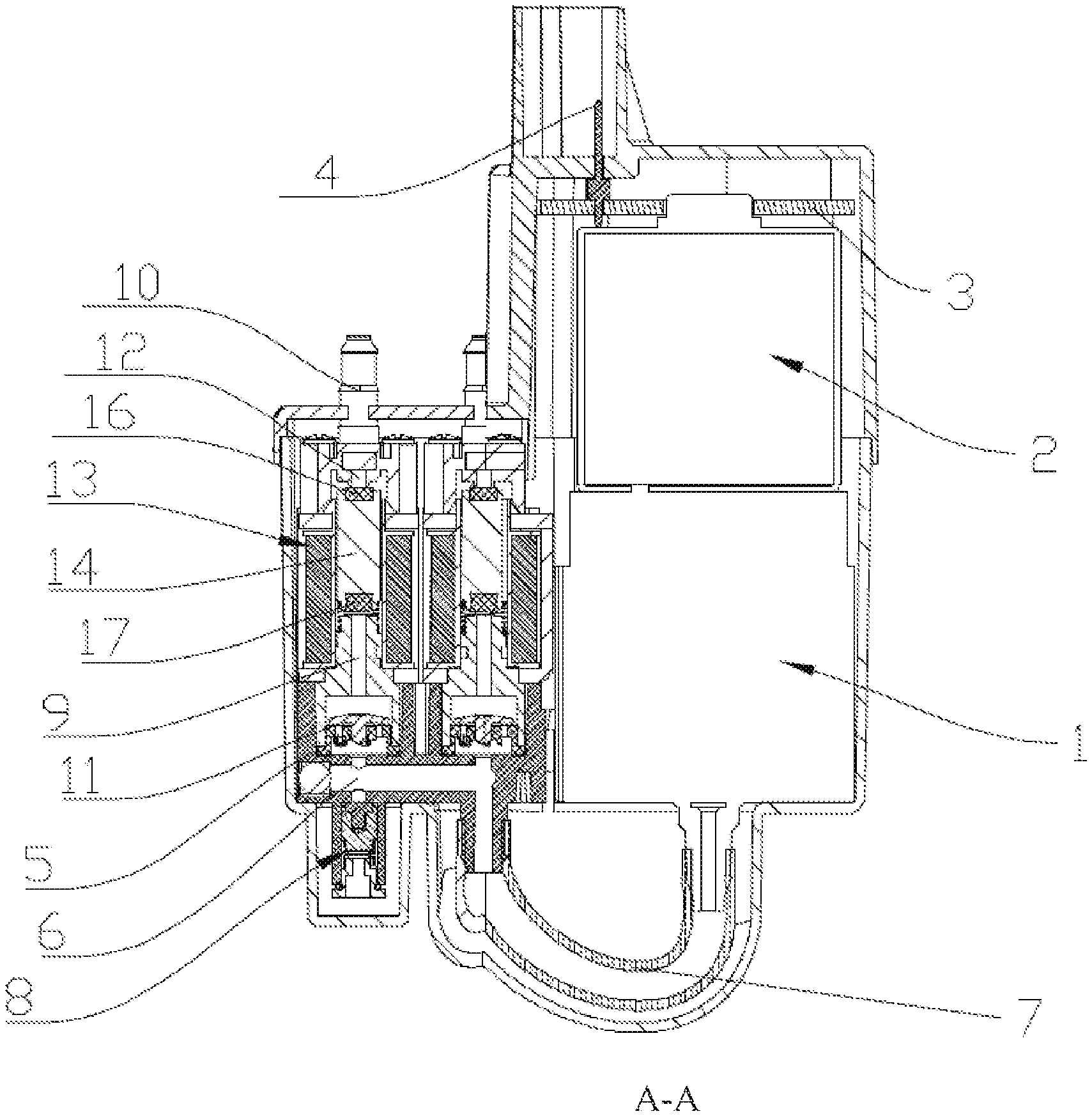
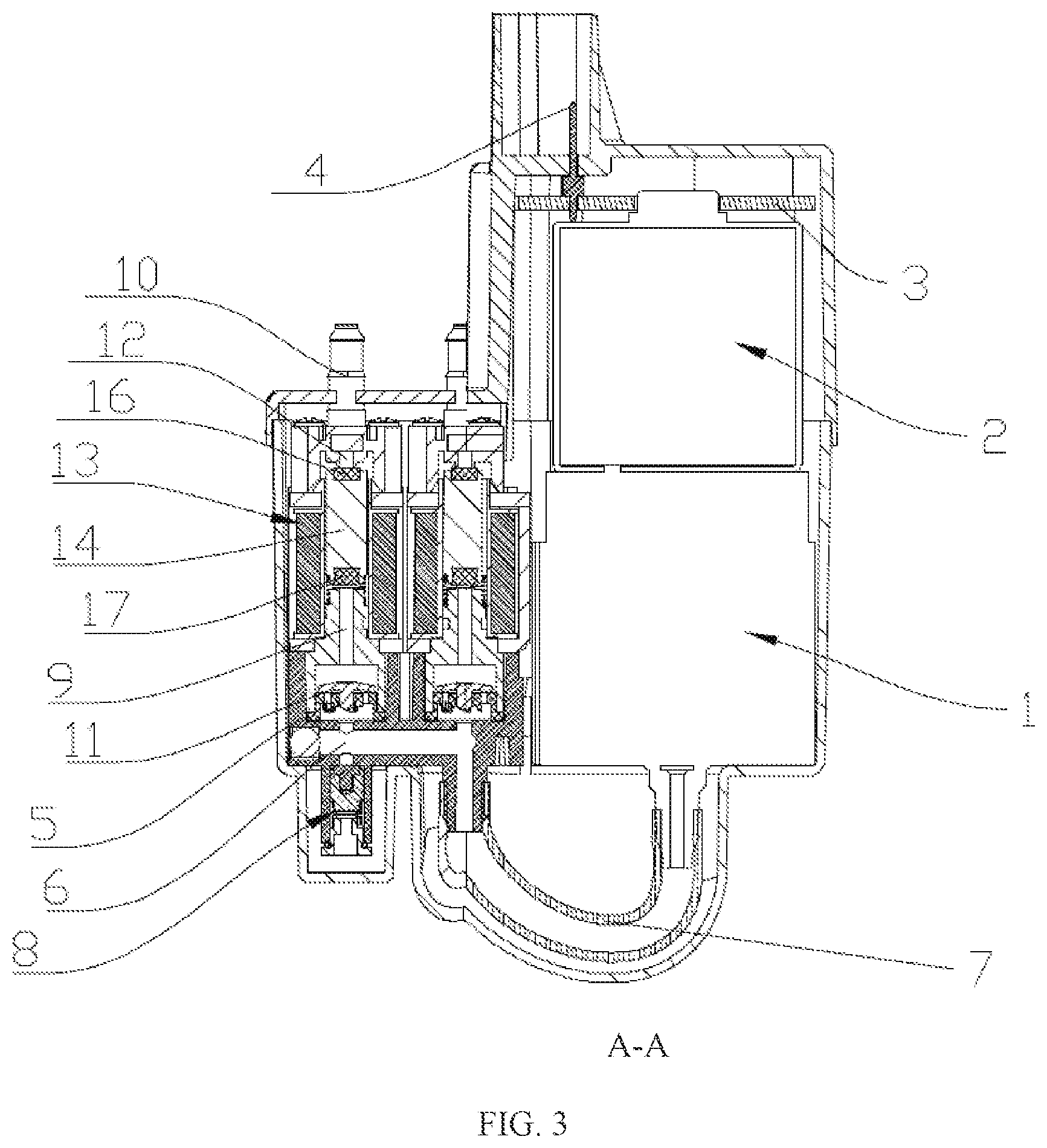
FIG. 3 is a hybrid sectional view and schematic view of the present invention taken along line A-A shown in FIG. 2, wherein the pump 1 and motor 2 are shown in schematic view;
FIG. 4 is a top view showing the structure of the present invention; and
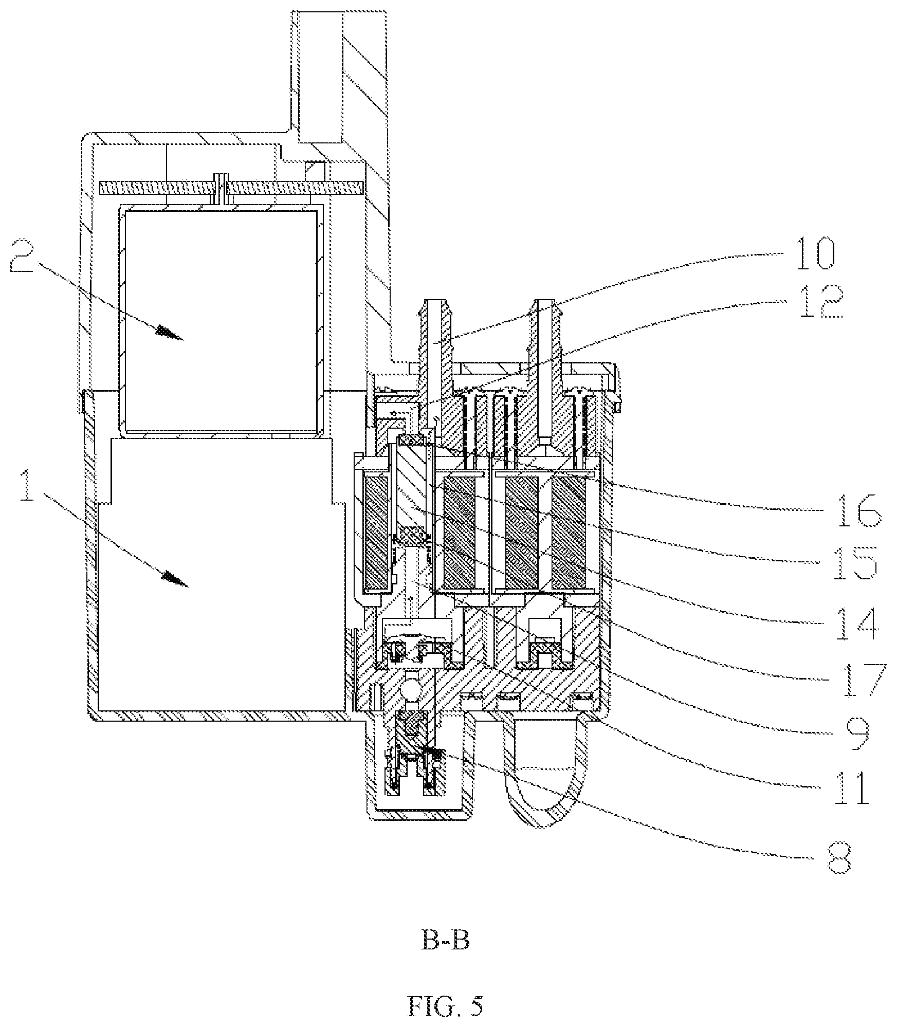
FIG. 5 is a hybrid sectional view and schematic view of the present invention taken along line B-B shown in FIG. 4, wherein the pump 1 and motor 2 are shown in schematic view.
DETAILED DESCRIPTION OF THE EMBODIMENTS
The drawings illustrate the structure of the present invention, and the related details will be further illustrated hereinafter with reference to the drawings. The pump-valve integrated mechanism is installed in a shell body and includes the air pump 1. The air pump 1 is driven by a power source, the power source is the motor 2. The motor is provided above the air pump 1 with a driving connection. Correspondingly, the motor 2 is provided with the PCBA 3. The connecting plug pin 4 is provided on the PCBA 3. The air pump 1 is connected to the valve base 5. Preferably, the valve base 5 is provided on a side of the air pump 1 to achieve a reasonable arrangement and a compact structure. The main air channel 6 is provided inside the valve base 5. The main air channel 6 of the valve base 5 is connected to the air pump 1 through the U-shaped air pipe 7. The main air channel 6 is provided with the decompression structure 8. The decompression structure 8 is a decompression hole provided on the main air channel 6. The decompression hole is correspondingly provided with a decompression valve. The decompression valve controls the on and off of the decompression hole according to the air pressure in the main air channel 6. The main air channel 6 is connected to an air inflation structure. Preferably, at least two air inflation structures are provided which enables the inflation of a plurality of the airbags at the same time. The air inflation structure includes the branch air channel 9 and the air nozzle 10. An inner end of the branch air channel 9 is connected to the main air channel 6. An outer end of the branch air channel 9 is connected to the air nozzle 10. The check valve 11 is provided inside the branch air channel 9. The branch air channel 9 between the check valve 11 and the air nozzle 10 is provided with the air deflation hole 12. A soundproof foam is further provided in the air deflation hole 12 to reduce noise during air deflation. The electromagnetic valve 13 is provided between the air nozzle 10, the air deflation hole 12 and the check valve 11. The electromagnetic valve 13 is a three-way, two-position valve. During air inflation, the electromagnetic valve 13 controls the check valve 11 to become connected to the air nozzle 10, and the air deflation hole 12 is closed. During air deflation, the electromagnetic valve 13 controls the air nozzle to become connected to the air deflation hole 12, and the check valve 11 is closed.
The electromagnetic valve 13 includes the valve rod 14. The valve rod is controlled by an electromagnetic coil and a resetting spring and is movably provided in the branch air channel 9. Moreover, the gap 15 is provided between the valve rod and the branch air channel 9 for ventilation. Preferably, a cylindrical side surface of the valve rod is provided with a flat surface. Two ends of the valve rod are respectively provided with the upper sealing gasket 16 and the lower sealing gasket 17. The upper sealing gasket 16 is matched with the air deflation hole 12, and the lower sealing gasket 16 is matched with the check valve 11. Moreover, the upper sealing gasket 16 and the lower sealing gasket 17 are rubber gaskets.
The working principle of the present invention is as follows. The motor 2 drives the air pump 1 to perform the air inflation, the air enters the main air channel 6 via the U-shaped air pipe 7, and the air in the main air channel 6 inflates the airbag via the branch air channel 9, the check valve 11, and the air nozzle 10. At this time, the electromagnetic valve 13 controls the check valve 11 to become connected to the air nozzle 10, and the air deflation hole 12 is closed. While, when the electromagnetic valve 13 controls the air nozzle 10 to become connected to the air deflation hole 12, and the check valve 11 is closed, the air in the air bag is released via the air nozzle 10, the branch air channel 9, and the air deflation hole 12. When an air pressure in the main air channel 6 is excessive, the decompression structure 8 will work to relieve the pressure.
To conclude, the foregoing merely described the preferred embodiments of the present invention, which is not intended to limit the scope of the present invention. Any modification, equivalent substitution, or improvement made without departing from the spirit and principle of the present invention should be considered as falling within the scope of the present invention.
* * * * *
D00000
D00001
D00002
D00003
D00004
D00005
XML
uspto.report is an independent third-party trademark research tool that is not affiliated, endorsed, or sponsored by the United States Patent and Trademark Office (USPTO) or any other governmental organization. The information provided by uspto.report is based on publicly available data at the time of writing and is intended for informational purposes only.
While we strive to provide accurate and up-to-date information, we do not guarantee the accuracy, completeness, reliability, or suitability of the information displayed on this site. The use of this site is at your own risk. Any reliance you place on such information is therefore strictly at your own risk.
All official trademark data, including owner information, should be verified by visiting the official USPTO website at www.uspto.gov. This site is not intended to replace professional legal advice and should not be used as a substitute for consulting with a legal professional who is knowledgeable about trademark law.