Systems for a water-cooled center housing for a turbocharger
Hastings , et al. February 16, 2
U.S. patent number 10,920,614 [Application Number 16/673,841] was granted by the patent office on 2021-02-16 for systems for a water-cooled center housing for a turbocharger. This patent grant is currently assigned to TURBONETICS HOLDINGS, INC.. The grantee listed for this patent is TURBONETICS HOLDINGS, INC.. Invention is credited to Michal Hastings, Brian G. Regnier.


View All Diagrams
| United States Patent | 10,920,614 |
| Hastings , et al. | February 16, 2021 |
Systems for a water-cooled center housing for a turbocharger
Abstract
Various systems are provided for a turbocharger center housing. In one example, a center housing for a turbocharger includes an internal water jacket including at least two ports, and a selectively pluggable interconnect positioned within the internal water jacket that, when plugged, blocks flow in the internal water jacket between the at least two ports in a first direction and, when unplugged, enables flow in the internal water jacket between the at least two ports in the first direction. In this way, flow may be directed through the center housing via different flow path configurations.
| Inventors: | Hastings; Michal (Moorpark, CA), Regnier; Brian G. (Redondo Beach, CA) | ||||||||||
|---|---|---|---|---|---|---|---|---|---|---|---|
| Applicant: |
|
||||||||||
| Assignee: | TURBONETICS HOLDINGS, INC.
(Moorpark, CA) |
||||||||||
| Family ID: | 74569983 | ||||||||||
| Appl. No.: | 16/673,841 | ||||||||||
| Filed: | November 4, 2019 |
| Current U.S. Class: | 1/1 |
| Current CPC Class: | F01P 3/20 (20130101); F01D 25/14 (20130101); F02B 37/013 (20130101); F16K 5/08 (20130101); F01P 7/14 (20130101); F01P 3/12 (20130101); F01P 2007/146 (20130101); F05D 2220/40 (20130101); F05D 2260/232 (20130101); F01P 2060/12 (20130101); F01P 7/048 (20130101); F05D 2260/20 (20130101); Y02T 10/12 (20130101) |
| Current International Class: | F02B 37/00 (20060101); F16K 5/08 (20060101); F02B 37/013 (20060101); F01D 25/14 (20060101); F01P 7/14 (20060101); F01D 25/12 (20060101) |
References Cited [Referenced By]
U.S. Patent Documents
| 2005/0210875 | September 2005 | Larue |
| 2012/0003081 | January 2012 | Woollenweber |
| 2012/0263589 | October 2012 | Iwata |
| 2013/0323020 | December 2013 | Bogner |
| 2016/0177814 | June 2016 | McHenry |
| 2018/0163620 | June 2018 | Eriksson |
Attorney, Agent or Firm: McCoy Russell LLP
Claims
The invention claimed is:
1. A center housing for a turbocharger, comprising: an internal water jacket including at least two ports; and a selectively pluggable interconnect positioned within the internal water jacket that, when plugged, blocks flow in the internal water jacket between the at least two ports in a first direction and, when unplugged, enables flow in the internal water jacket between the at least two ports in the first direction.
2. The center housing of claim 1, wherein the internal water jacket includes an annular passage that encircles a central axis of the center housing, and the first direction is a first radial direction.
3. The center housing of claim 2, wherein the selectively pluggable interconnect, when plugged, enables flow in the internal water jacket between the at least two ports in a second radial direction, opposite the first radial direction, and, when unplugged, enables flow in the internal water jacket between at least two ports in the first radial direction and the second radial direction.
4. The center housing of claim 1, further comprising a routing port that extends from an external surface of the center housing to the selectively pluggable interconnect, the routing port shaped to receive one of a shorter routing plug and a longer routing plug.
5. The center housing of claim 4, wherein the selectively pluggable interconnect is unplugged with the shorter routing plug is installed in the routing port and plugged when the longer routing plug is installed in the routing port.
6. The center housing of claim 4, wherein the longer routing plug fills an entirety of a cavity of the selectively pluggable interconnect when installed in the routing port, and the shorter routing plug does not fill the entirety of the cavity.
7. The center housing of claim 1, wherein the at least two ports include an inlet port and an outlet port, the outlet port positioned vertically above the inlet port, a central axis of the inlet port parallel to a central axis of the outlet port.
8. The center housing of claim 7, wherein the inlet port and the outlet port are positioned on a same side of the center housing.
9. The center housing of claim 7, wherein the inlet port and the outlet port are positioned on opposite sides of the center housing.
10. A kit for a turbocharger, comprising: a center housing including an internal water jacket, the internal water jacket including a plurality of water ports that each extend to an external surface of the center housing, the center housing further including a first routing port extending from the external surface to a first selectively pluggable interconnect within the internal water jacket and a second routing port extending from the external surface to a second selectively pluggable interconnect within the internal water jacket; a plurality of water port plugs, each of the plurality of water port plugs configured to be interchangeably inserted into any port of the plurality of water ports; and a plurality of routing plugs configured to be interchangeably inserted into either of the first routing port and the second routing port, the plurality of routing plugs including at least one longer plug and at least one shorter plug.
11. The kit of claim 10, wherein the at least one longer plug, when inserted into the first routing port, blocks flow through the first routing port and blocks flow through the first selectively pluggable interconnect and, when inserted into the second routing port, blocks flow through the second routing port and blocks flow through the second selectively pluggable interconnect.
12. The kit of claim 10, wherein the at least one shorter plug, when inserted into the first routing port, blocks flow through the first routing port without blocking flow through the first selectively pluggable interconnect and, when inserted into the second routing port, blocks flow through the second routing port without blocking flow through the second selectively pluggable interconnect.
13. The kit of claim 10, wherein the plurality of water ports comprises a first inlet water port, a second inlet water port, a first outlet water port, and a second outlet water port, the first inlet water port vertically aligned with the second inlet water port and positioned vertically below the first outlet water port, the second outlet water port vertically aligned with the first outlet water port and positioned vertically above the second inlet water port.
14. The kit of claim 13, wherein the plurality of water port plugs includes two water port plugs and the plurality of routing plugs includes two shorter plugs and one longer plug.
15. The kit of claim 13, wherein the first routing port is positioned vertically between the first inlet water port and the first outlet water port, and the second routing port is positioned vertically between the second inlet water port and the second outlet water port.
16. A center housing for a turbocharger, comprising: an internal water jacket including an annular passage that encircles a central axis, the annular passage divided between a first portion and a second portion via a first interconnect and a second interconnect; a first routing port extending between an exterior surface of the center housing and the first interconnect; and a second routing port extending between the exterior surface and the second interconnect.
17. The center housing of claim 16, further comprising: a first inlet water port and a first outlet water port that each extend between the annular passage and the exterior surface on a first side; a second inlet water port and a second outlet water port that each extend between the annular passage and the exterior surface on a second side; a first water port sealing plug positioned in one of the first inlet water port and the second inlet water port; a second water port sealing plug positioned in one of the first outlet water port and the second outlet water port; a first routing plug positioned in the first routing port; and a second routing plug positioned in the second routing port.
18. The center housing of claim 17, wherein the first water port sealing plug is positioned in the first inlet water port, the second water port sealing plug is positioned in the first outlet water port, the first routing plug is a short plug that seals the first routing port without sealing the first interconnect, and the second routing plug is a long plug that seals the second routing port and seals the second interconnect.
19. The center housing of claim 17, wherein the first water port sealing plug is positioned in the first inlet water port, the second water port sealing plug is positioned in the second outlet water port, the first routing plug is a short plug that seals the first routing port without sealing the first interconnect, and the second routing plug is a short plug that seals the second routing port without sealing the second interconnect.
20. The center housing of claim 17, wherein the first inlet water port and the second inlet water port are connected to the first portion of the annular passage, the first outlet water port and the second outlet water port are connected to the second portion of the annular passage, the first routing port is positioned vertically between the first inlet water port and the first outlet water port, and the second routing port is positioned vertically between the second inlet water port and the second outlet water port.
Description
BACKGROUND
Technical Field
Embodiments of the subject matter disclosed herein relate to a water-cooled center housing for a turbocharger.
Discussion of Art
Engine systems, such as those included in a vehicle (e.g., a motor vehicle), may include a turbocharger to increase a pressure (e.g., boost) of air provided to an intake of an engine. The turbocharger may include a compressor driven by a turbine, the turbine arranged in an exhaust passage of the engine and the compressor arranged in an intake passage of the engine. Thus, combusted exhaust gases may drive rotation of the turbine which, in turn, drives rotation of the compressor, thereby providing power to boost the incoming intake air. The turbine and the compressor are driveably connected via a drive shaft encased in a center housing. The center housing may further house one or more bearings, such as a journal bearing, a thrust bearing, and/or a ball bearing.
During turbocharger operation, hot exhaust gases may increase a temperature of the turbine. Further, a temperature of the center housing and/or the bearing may increase due to proximity to the turbine. Exposure to high temperatures may degrade turbocharger components, such as the bearing(s), and/or lead to oil coking around the drive shaft. Therefore, the center housing may include a cooling system for mitigating heat transfer from the turbine to the bearing(s) or the compressor. In some examples, one or more water jackets may be incorporated into the center housing to decrease temperatures near the turbocharger bearing(s). Water and/or antifreeze (e.g., referred to herein as "cooling fluid" or "coolant") may flow into and out of the water jacket(s) through one or more ports, providing a supply of cooling fluid during operation. Such center housings may be referred to as "water-cooled" center housings. In some examples, the cooling fluid may be provided by an engine cooling system, such that cooling fluid may be cooled in a radiator and pumped to the turbocharger by one or more pumps. In other examples, the engine system may include a separate reservoir of turbocharger cooling fluid and may further include one or more additional pumps to direct cooling fluid through the turbocharger water jacket(s).
Current turbocharger center housings may include two ports located opposite each other across a width of the center housing, with a first port functioning as an inlet port for the cooling fluid to flow into the water jacket and a second port functioning as an outlet port for the cooling fluid to flow out of the water jacket. Thus, water lines connecting the turbocharger center housing to the cooling system may be positioned on opposite sides of the center housing, which may constrain installation of the turbocharger. Because engine system packaging space may be limited, the rigid configuration of the water lines may restrict turbocharger placement and/or prevent turbocharger installation if the water line configuration cannot be accommodated. For example, the turbocharger may only be installed in a position such that water lines may be routed to each side of the center housing without interfering with engine operation. As a result, users may be constrained to installing the turbocharger in a suboptimal location, become frustrated during turbocharger installation, or forgo turbocharger installation all together.
BRIEF DESCRIPTION
In one embodiment, a center housing for a turbocharger a center housing for a turbocharger includes an internal water jacket including at least two ports, and a selectively pluggable interconnect positioned within the internal water jacket that, when plugged, blocks flow in the internal water jacket between the at least two ports in a first direction and, when unplugged, enables flow in the internal water jacket between the at least two ports in the first direction.
BRIEF DESCRIPTION OF THE DRAWINGS
FIG. 1 shows a schematic diagram of a vehicle with an engine comprising a turbocharger arrangement, according to an embodiment of the present disclosure.
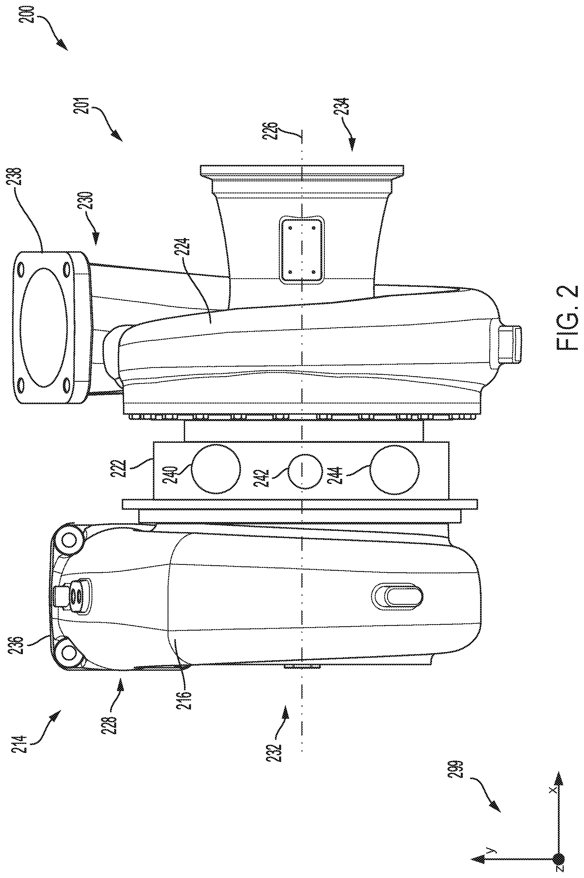
FIG. 2 shows an external view of an example turbocharger arrangement including a water-cooled center housing.
FIG. 3 shows an external view of the water-cooled center housing of FIG. 2.
FIG. 4 shows a cross-sectional view of a first configuration of a center housing assembly.
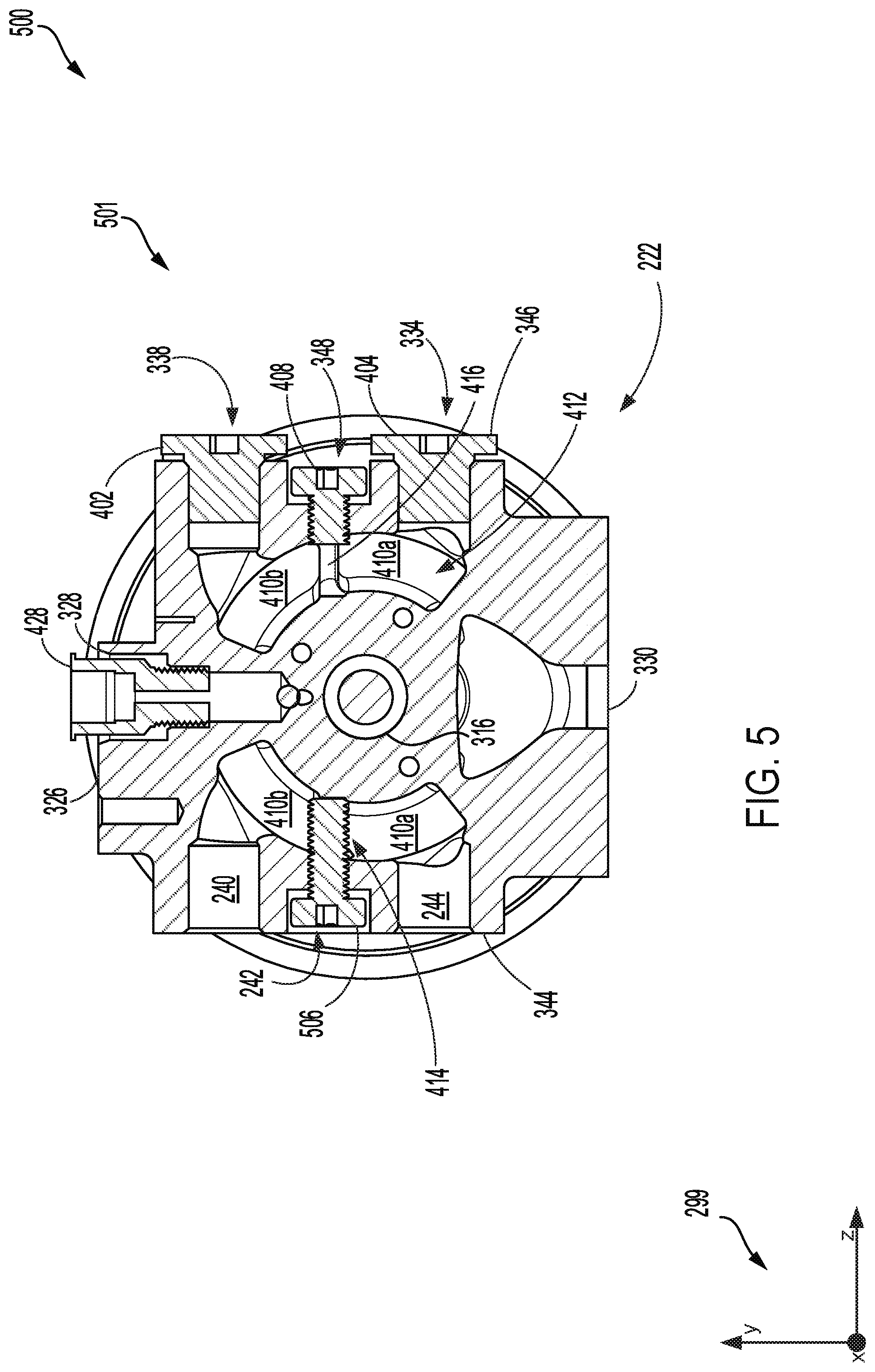
FIG. 5 shows a cross-sectional view of a second configuration of a center housing assembly.
FIG. 6 shows a first example water line configuration for the center housing of FIG. 3.
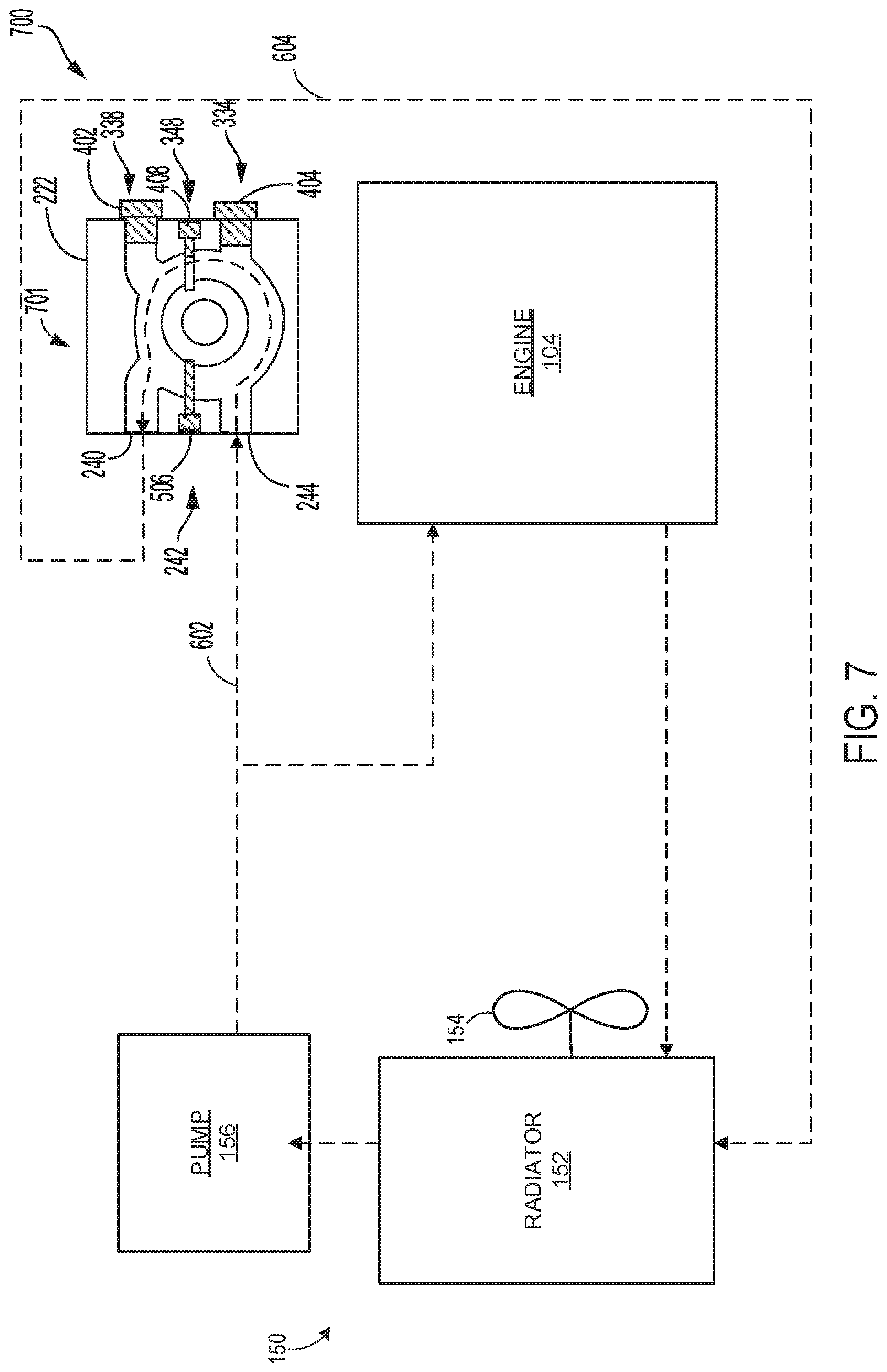
FIG. 7 shows a second example water line configuration for the center housing of FIG. 3.
FIG. 8 shows a third example water line configuration for the center housing of FIG. 3.
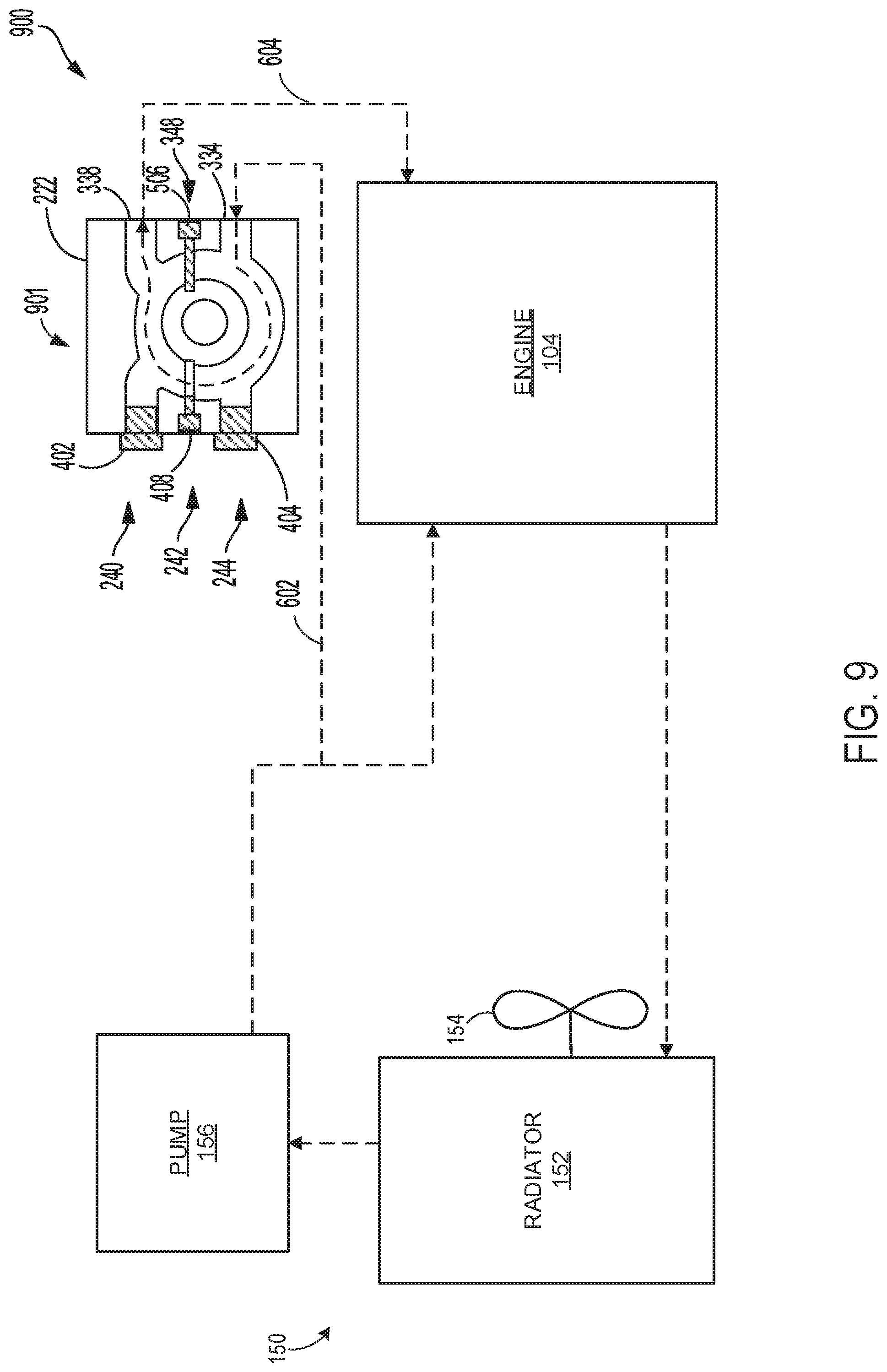
FIG. 9 shows a fourth example water line configuration for the center housing of FIG. 3.
FIG. 10 shows a line of turbochargers including four turbochargers, each having a different center housing assembly configuration.
FIG. 11 shows an example method for flowing cooling fluid through a turbocharger center housing during engine system operation.
DETAILED DESCRIPTION
The following description relates to embodiments of a center housing of a turbocharger. As one example, the turbocharger may include a turbine casing that houses a turbine wheel, a compressor casing that houses a compressor wheel, and a center housing surrounding a shaft connecting the turbine wheel and the compressor wheel and one or more bearings. The center housing may include a water jacket and an oil jacket. Further, the center housing may include multiple water jacket ports, including two water jacket ports on a first side of the housing (e.g., on a first radial edge of the center housing) and two on a second side of the housing (e.g., a second radial edge of the center housing that is opposite the first radial edge) that is opposite of the first side. Because of the multiple water jacket ports, a cooling system of an engine may be coupled to the center housing in a variety of configurations by using plugs to seal water jacket ports that are not in use. In one example, the center housing may be coupled to the cooling system such that cooling fluid from the cooling system enters the water jacket on one side of the housing (e.g., on the first radial edge of the center housing), and leaves the water jacket on the opposite side of the housing (e.g., on the second radial edge of the center housing). In another example, the center housing may be installed such that the cooling fluid enters the water jacket on one side of the housing and leaves the water jacket on the same side of the housing.
In this way, the center housing may be installed in multiple configurations, which may increase user flexibility during installation. For example, the user may select one of multiple configurations during installation, which may allow the turbocharger to be more easily installed in the available engine packaging space. Further, the center housing may simplify additional engine modifications. For example, a user may change the center housing configuration (e.g., by changing the location of one or more plugs and water lines to change a flow path) while installing other engine components that may interfere with the current center housing configuration. Because the center housing configuration may be altered by rearranging a plug/water line configuration, such alteration may be performed without removing the turbocharger or center housing from the engine system.
FIG. 1 shows an example of a vehicle engine system that includes a turbocharger for providing compressed air to the engine, the turbocharger and the engine both cooled by an engine cooling system. The turbocharger may include a water-cooled center housing coupled between a turbine of the turbocharger and a compressor of the turbocharger, as shown in FIG. 2, and may be adapted between a plurality of cooling fluid configurations. A perspective view of the water-cooled center housing is shown in FIG. 3. The water-cooled center housing includes a plurality of plugs, which may be arranged to select between distinct flow path configurations through the water jacket. A first flow path configuration is shown in FIG. 4, where coolant enters the water jacket on one side of the housing and leaves the water jacket on the opposite side of the housing. A second flow path configuration is shown in FIG. 5, where coolant enters the water jacket on one side of the housing and leaves the water jacket on the same side of the housing. Four example configurations of the center housing coupled to the engine cooling system are shown in FIGS. 6-9. FIG. 10 shows a turbocharger line (e.g., a line of turbochargers) including four turbochargers, each having a distinct center housing configuration. Additionally, an example method for flowing coolant through the water-cooled turbocharger center housing during engine operation is provided in FIG. 11.
The approach described herein may be employed in a variety of engine types and a variety of engine-driven systems. Some of these systems may be stationary, while others may be on semi-mobile or mobile platforms. Semi-mobile platforms may be relocated between operational periods, such as mounted on flatbed trailers. Mobile platforms include self-propelled vehicles. Such vehicles can include on-road transportation vehicles, as well as mining equipment, marine vessels, rail vehicles, and other off-highway vehicles (OHV). For clarity of illustration, an automobile is provided as an example of a mobile platform supporting a system incorporating an embodiment of the invention.
Referring to FIG. 1, an embodiment of a system in which a turbocharger arrangement may be installed is shown. Specifically, FIG. 1 shows a block diagram of an embodiment of a vehicle system 100, herein depicted as a motor vehicle 106 (e.g., automobile), configured to run on a road 102 via a plurality of wheels 112. As depicted, the motor vehicle 106 includes an engine 104. The engine includes a plurality of cylinders 101 (only one representative cylinder shown in FIG. 1) that each include at least one intake valve 103, at least one exhaust valve 105, and at least one fuel injector 107. Each intake valve, exhaust valve, and fuel injector may include an actuator that may be actuated via a signal from a controller 110 of the engine 104. In other non-limiting embodiments, the engine 104 may be a stationary engine, such as in a power-plant application, or an engine in a marine vessel or other off-highway vehicle propulsion system as noted above.
The engine 104 receives intake air for combustion from an intake passage 114. The intake passage 114 includes an air filter 160 that filters air from outside of the motor vehicle. Exhaust gas resulting from combustion in the engine is supplied to an exhaust passage 116. Exhaust gas flows through the exhaust passage 116 and out of an exhaust system of the motor vehicle. Combustion in the cylinder drives rotation of a crankshaft 164. In one example, the engine is a diesel engine that combusts air and diesel fuel through compression ignition. In another example, the engine is a dual or multi-fuel engine that may combust a mixture of gaseous fuel and air upon injection of diesel fuel during compression of the air-gaseous fuel mix. In other non-limiting embodiments, the engine may additionally or alternatively combust fuel including gasoline, kerosene, natural gas, biodiesel, or other petroleum distillates of similar density through compression ignition and/or spark ignition.
As depicted in FIG. 1, the engine is coupled to an electric power generation system that includes an alternator/generator 122. For example, the engine is a diesel and/or natural gas engine that generates a torque output that is transmitted to the alternator/generator 122, which is mechanically coupled to the crankshaft 164, as well as to at least one of the plurality of wheels 112 to provide motive power to propel the motor vehicle. The alternator/generator 122 produces electrical power that may be stored and applied for subsequent propagation to a variety of downstream electrical components. In one example, the alternator/generator 122 may be coupled to an electrical system 126. The electrical system 126 may include one or more electrical loads configured to run on electricity generated by the alternator/generator 122, such as vehicle headlights, a cabin ventilation system, and an entertainment system, and may further include an energy storage device (e.g., a battery) configured to be charged by electricity generated by the alternator/generator 122. In some examples, the vehicle may be a diesel electric vehicle, and the alternator/generator 122 may provide electricity to one or more electric motors to drive the wheels 112.
The vehicle system may include a turbocharger 120 that is arranged between the intake passage and the exhaust passage. The turbocharger 120 increases an air charge of ambient air drawn into the intake passage in order to provide greater charge density during combustion to increase power output and/or engine opera
D00000
D00001
D00002
D00003
D00004
D00005
D00006
D00007
D00008
D00009
D00010
D00011
XML
uspto.report is an independent third-party trademark research tool that is not affiliated, endorsed, or sponsored by the United States Patent and Trademark Office (USPTO) or any other governmental organization. The information provided by uspto.report is based on publicly available data at the time of writing and is intended for informational purposes only.
While we strive to provide accurate and up-to-date information, we do not guarantee the accuracy, completeness, reliability, or suitability of the information displayed on this site. The use of this site is at your own risk. Any reliance you place on such information is therefore strictly at your own risk.
All official trademark data, including owner information, should be verified by visiting the official USPTO website at www.uspto.gov. This site is not intended to replace professional legal advice and should not be used as a substitute for consulting with a legal professional who is knowledgeable about trademark law.