Robotic floor cleaning device with expandable wheels
Ebrahimi Afrouzi , et al. February 9, 2
U.S. patent number 10,913,310 [Application Number 16/247,092] was granted by the patent office on 2021-02-09 for robotic floor cleaning device with expandable wheels. The grantee listed for this patent is Ali Ebrahimi Afrouzi, Shahin Fathi Djalali. Invention is credited to Ali Ebrahimi Afrouzi, Shahin Fathi Djalali.


| United States Patent | 10,913,310 |
| Ebrahimi Afrouzi , et al. | February 9, 2021 |
Robotic floor cleaning device with expandable wheels
Abstract
Provided is a wheel including: a main housing with a series of apertures disposed radially thereabout; an inner shaft disposed within the main housing and rotatably coupled thereto; a set of spokes distributed radially around the inner shaft and attached thereto at a first end, each spoke positioned within one of the series of apertures in the main housing; a set of linkages distributed radially around the inner shaft and attached to a second end of the spokes, the linkages positioned within the apertures; and a set of rollers distributed radially around the inner shaft and mounted on the linkages; wherein the spokes, linkages, and rollers can be moved from a first, contracted position, to a second, expanded position.
| Inventors: | Ebrahimi Afrouzi; Ali (San Jose, CA), Fathi Djalali; Shahin (San Leandro, CA) | ||||||||||
|---|---|---|---|---|---|---|---|---|---|---|---|
| Applicant: |
|
||||||||||
| Family ID: | 1000003820653 | ||||||||||
| Appl. No.: | 16/247,092 | ||||||||||
| Filed: | January 14, 2019 |
Related U.S. Patent Documents
| Application Number | Filing Date | Patent Number | Issue Date | ||
|---|---|---|---|---|---|
| 15447623 | Mar 2, 2017 | 10214050 | |||
| 62302942 | Mar 3, 2016 | ||||
| Current U.S. Class: | 1/1 |
| Current CPC Class: | B60B 1/06 (20130101); B60B 19/04 (20130101); A47L 11/4011 (20130101); A47L 11/4072 (20130101); A47L 11/4066 (20130101); A47L 2201/04 (20130101) |
| Current International Class: | B60B 19/04 (20060101); A47L 11/40 (20060101); B60B 1/06 (20060101) |
| Field of Search: | ;301/5.305,12.2,45 |
References Cited [Referenced By]
U.S. Patent Documents
| 1371980 | March 1921 | Ramsey |
| 1408885 | March 1922 | Humphery |
| 1435042 | November 1922 | Zottoli |
| 1450626 | April 1923 | Atwood |
| 1469393 | October 1923 | O'Connor |
| 1890872 | December 1932 | Van Kleeck |
| 2610898 | September 1952 | Smith |
| 2916331 | December 1959 | Gardner |
| 2924486 | February 1960 | Blaschke |
| 3672458 | June 1972 | Mackerle |
| 3995909 | December 1976 | Van Der Lely |
| 4335899 | June 1982 | Hiscock |
| 4420192 | December 1983 | Holchuk |
| 4601519 | July 1986 | D'Andrade |
| 4643696 | February 1987 | Law |
| 4648853 | March 1987 | Siegfried |
| 4773889 | September 1988 | Rosenwinkel |
| 5487692 | January 1996 | Mowrer |
| 5492390 | February 1996 | Kugelmann, Sr. |
| 5690375 | November 1997 | Schneider |
| 5894621 | April 1999 | Kubo |
| 6860346 | March 2005 | Burt |
| 7503567 | March 2009 | Frankie |
| 7568536 | August 2009 | Yu |
| 7594527 | September 2009 | Thompson |
| 7730978 | June 2010 | Dixon |
| 8007341 | August 2011 | Su |
| 8814626 | August 2014 | Smith |
| 9073587 | July 2015 | Kim |
| 9168786 | October 2015 | Schlee |
| 9616707 | April 2017 | Jochim |
| 9757978 | September 2017 | Emigh |
| 9878576 | January 2018 | Hein |
| 9950567 | April 2018 | Pfrenger |
| 10214050 | February 2019 | Ebrahimi Afrouzi |
| 2003/0037410 | February 2003 | Yamaguchi |
| 2010/0141018 | June 2010 | McCue |
| 2010/0187779 | July 2010 | Potter |
| 2010/0224427 | September 2010 | Nuchter |
| 2013/0014580 | January 2013 | Lin |
| 2013/0167991 | July 2013 | Donohue |
| 2014/0117637 | May 2014 | Solheim |
| 2014/0252844 | September 2014 | Riwan |
| 2015/0084398 | March 2015 | Lee |
| 2015/0151572 | June 2015 | Parrott |
| 2015/0165498 | July 2015 | Kim |
| 2016/0193877 | July 2016 | Jang |
| 2017/0349003 | December 2017 | Joso |
| 2018/0020894 | January 2018 | Sauer |
| 2018/0022148 | January 2018 | Lin |
| 2018/0126779 | May 2018 | Brandl |
| 101407662 | Jul 2014 | KR | |||
Assistant Examiner: Williams; Maurice L
Parent Case Text
CROSS-REFERENCE TO RELATED APPLICATIONS
This application is a continuation of U.S. patent application Ser. No. 15/447,623, filed Mar. 2, 2017, which is a Non-Provisional Patent Application of U.S. Provisional Patent Application No. 62/302,942 filed Mar. 3, 2016, each of which are hereby incorporated by reference.
Claims
The invention claimed is:
1. A wheel comprising: a main housing with a series of apertures disposed radially thereabout; an inner shaft disposed within the main housing and rotatably coupled thereto; a set of spokes distributed radially around the inner shaft and attached thereto at a first end, each spoke positioned within one of the series of apertures in the main housing; a set of linkages distributed radially around the inner shaft and attached to a second end of the spokes, the linkages positioned within the apertures; and a set of rollers distributed radially around the inner shaft and mounted on the linkages; wherein the spokes, linkages, and rollers can be moved from a first, contracted position in which the spokes are positioned at a first angle with respect to a radius line connecting the center of the inner shaft and the first end of the respective spoke and in which the linkages and the rollers are pulled by the spokes towards the inner shaft, to a second, expanded position, in which the spokes are positioned at a second angle, greater than the first angle, with respect to the radius line connecting the center of the inner shaft and the first end of the respective spoke and the linkages and in which the rollers are pushed outward from the inner shaft by clockwise or counter-clockwise rotation of the inner shaft relative to the main housing.
2. The wheel of claim 1, wherein a sleeve is provided around each aperture.
3. The wheel of claim 1, wherein the spokes, linkages, and rollers are maintained at any position between the first, contracted position and the second, expanded position.
4. The wheel of claim 1, wherein the wheel has between 10 and 20 apertures, spokes, linkages, and rollers.
5. The wheel of claim 1, wherein the wheel further comprises one or more sensors.
6. The wheel of claim 5, wherein the one or more sensors measure a wheel tension.
7. The wheel of claim 6, wherein the wheel expands when the wheel tension is above a first predetermined threshold and retracts when the wheel tension is below a second predetermined threshold.
8. The wheel of claim 5, wherein the one or more sensors measure a wheel speed.
9. The wheel of claim 8, wherein the wheel expands and retracts based on data from a sensor monitoring a rate of rotation of the wheel and an expected rate of rotation of the wheel determined based on power supplied to a motor that drives the wheels.
10. The wheel of claim 5, wherein the movement of the wheel from the first, contracted position to the second, expanded position is at least partially based on data collected by the one or more sensors.
11. The wheel of claim 1, wherein the wheel is a wheel of a robotic device.
12. A robotic device comprising: a chassis including a set of wheels; a motor to drive the wheels; a central processing unit; a battery to power the motor; and one or more sensors; wherein each wheel comprises: a main housing with a series of apertures disposed radially thereabout; an inner shaft disposed within the main housing and rotatably coupled thereto; a set of spokes distributed radially around the inner shaft and attached thereto at a first end, each spoke positioned within one of the series of apertures in the main housing; a set of linkages distributed radially around the inner shaft and attached to a second end of the spokes, the linkages positioned within the apertures; and a set of rollers distributed radially around the inner shaft and mounted on the linkages; whereby the spokes, linkages, and rollers can be moved from a first, contracted position in which the spokes are positioned at a first angle with respect to a radius line connecting the center of the inner shaft and the first end of the respective spoke and in which the linkages and the rollers are pulled by the spokes towards the inner shaft, to a second, expanded position, in which the spokes are positioned at a second angle, greater than the first angle, with respect to the radius line connecting the center of the inner shaft and the first end of the respective spoke and the linkages and in which the rollers are pushed outward from the inner shaft by clockwise or counter-clockwise rotation of the inner shaft relative to the main housing.
13. The robotic device of claim 12, wherein a sleeve is provided around each aperture.
14. The robotic device of claim 12, wherein the spokes, linkages, and rollers are maintained at any position between the first, contracted position and the second, expanded position.
15. The robotic device of claim 12, wherein each wheel has between 10 and 20 apertures, spokes, linkages, and rollers.
16. The robotic device of claim 12, wherein the one or more sensors measure a wheel tension.
17. The robotic device of claim 16, wherein the wheel expands when the wheel tension is above a first predetermined threshold and retracts when the wheel tension is below a second predetermined threshold.
18. The robotic device of claim 12, wherein the one or more sensors measure a wheel speed.
19. The robotic device of claim 18, wherein the wheel expands and retracts based on data from the one or more sensors monitoring the wheel speed and an expected wheel speed determined based on an amount of power supplied to the motor.
20. The robotic device of claim 12, wherein the movement of the wheel from the first, contracted position to the second, expanded position is at least partially based on data collected by the one or more sensors.
Description
FIELD OF THE DISCLOSURE
The present invention relates to robotic floor cleaning devices, and, more particularly, the wheels of robotic floor cleaning devices.
BACKGROUND
Robotic floor cleaning devices are being used with increasing frequency to maintain clean floors in residential and commercial settings.
One problem in designing robotic floor cleaning devices is selecting a wheel size for the device. Larger wheels may aid a device in driving over obstacles and may allow the device more autonomy and mobility. However, smaller wheels may be better for navigating through environments with lots of obstacles near each other. Additionally, larger wheels may cause the chassis of a robotic floor cleaning device to further from the work surface, which may affect the cleaning efficacy of the device. A need exists for a robotic floor cleaning device that can expand wheels for driving over obstacles when necessary, and contract them when the larger wheel size is not needed.
SUMMARY
The following presents a simplified summary of some embodiments of the techniques described herein in order to provide a basic understanding of the invention. This summary is not an extensive overview of the invention. It is not intended to identify key/critical elements of the invention or to delineate the scope of the invention. Its sole purpose is to present some embodiments of the invention in a simplified form as a prelude to the more detailed description that is presented below.
Some aspects provide a wheel including: a main housing with a series of apertures disposed radially thereabout; an inner shaft disposed within the main housing and rotatably coupled thereto; a set of spokes distributed radially around the inner shaft and attached thereto at a first end, each spoke positioned within one of the series of apertures in the main housing; a set of linkages distributed radially around the inner shaft and attached to a second end of the spokes, the linkages positioned within the apertures; and a set of rollers distributed radially around the inner shaft and mounted on the linkages; wherein the spokes, linkages, and rollers can be moved from a first, contracted position in which the spokes are positioned at a first angle with respect to a radius line connecting the center of the inner shaft and the first end of the respective spoke and in which the linkages and the rollers are pulled by the spokes towards the inner shaft, to a second, expanded position, in which the spokes are positioned at a second angle, greater than the first angle, with respect to the radius line connecting the center of the inner shaft and the first end of the respective spoke and the linkages and in which the rollers are pushed outward from the inner shaft by clockwise or counter-clockwise rotation of the inner shaft relative to the main housing.
Some aspects provide a robotic device including: a chassis including a set of wheels; a motor to drive the wheels; a central processing unit; a battery to power the motor; and one or more sensors; wherein each wheel includes: a main housing with a series of apertures disposed radially thereabout; an inner shaft disposed within the main housing and rotatably coupled thereto; a set of spokes distributed radially around the inner shaft and attached thereto at a first end, each spoke positioned within one of the series of apertures in the main housing; a set of linkages distributed radially around the inner shaft and attached to a second end of the spokes, the linkages positioned within the apertures; and a set of rollers distributed radially around the inner shaft and mounted on the linkages; whereby the spokes, linkages, and rollers can be moved from a first, contracted position in which the spokes are positioned at a first angle with respect to a radius line connecting the center of the inner shaft and the first end of the respective spoke and in which the linkages and the rollers are pulled by the spokes towards the inner shaft, to a second, expanded position, in which the spokes are positioned at a second angle, greater than the first angle, with respect to the radius line connecting the center of the inner shaft and the first end of the respective spoke and the linkages and in which the rollers are pushed outward from the inner shaft by clockwise or counter-clockwise rotation of the inner shaft relative to the main housing.
BRIEF DESCRIPTION OF DRAWINGS
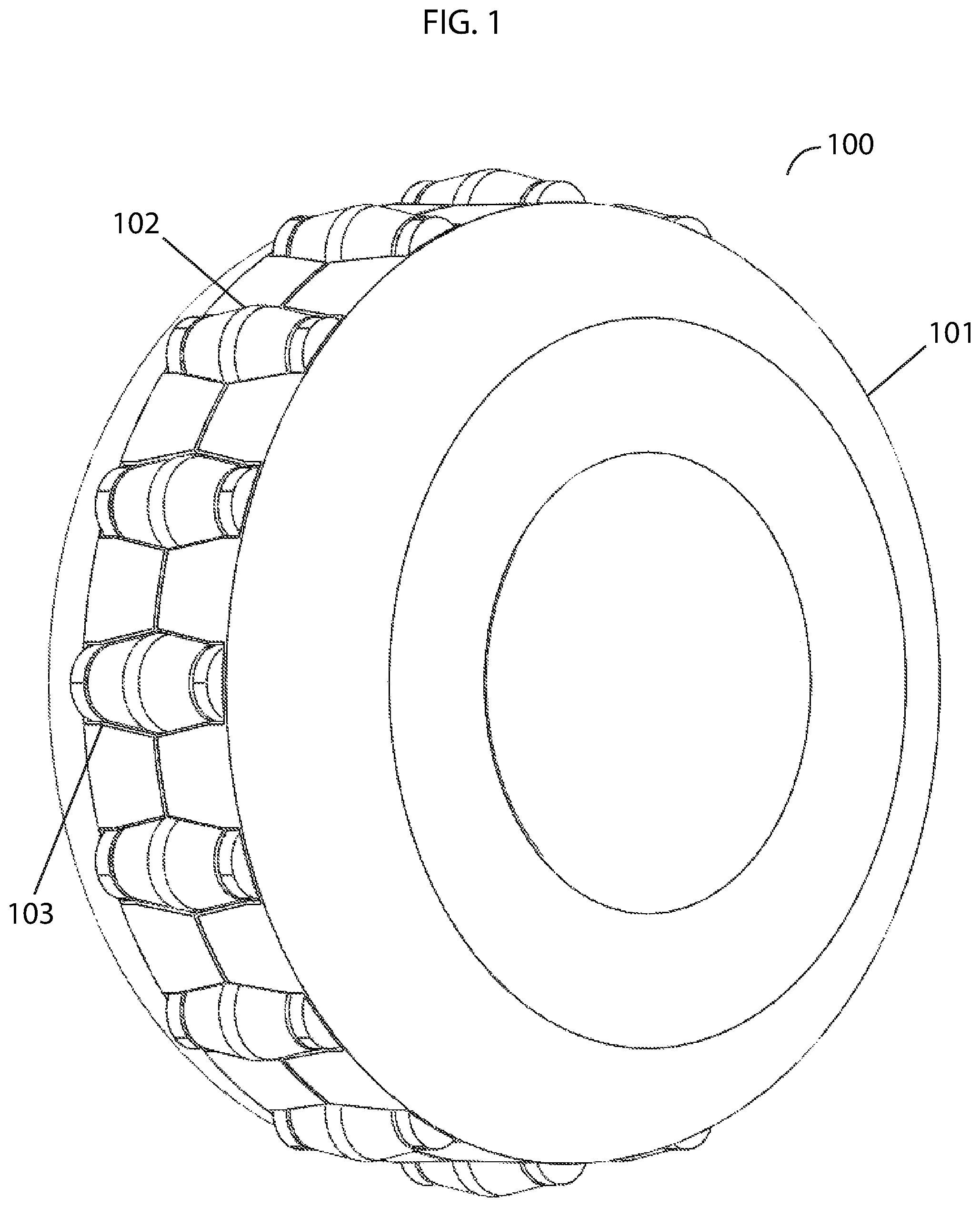
FIG. 1 illustrates a perspective view of an example of an expandable wheel in a contracted position, embodying features of the present invention.
FIG. 2 illustrates a perspective view of an example of an expandable wheel in an expanded position, embodying features of the present invention.
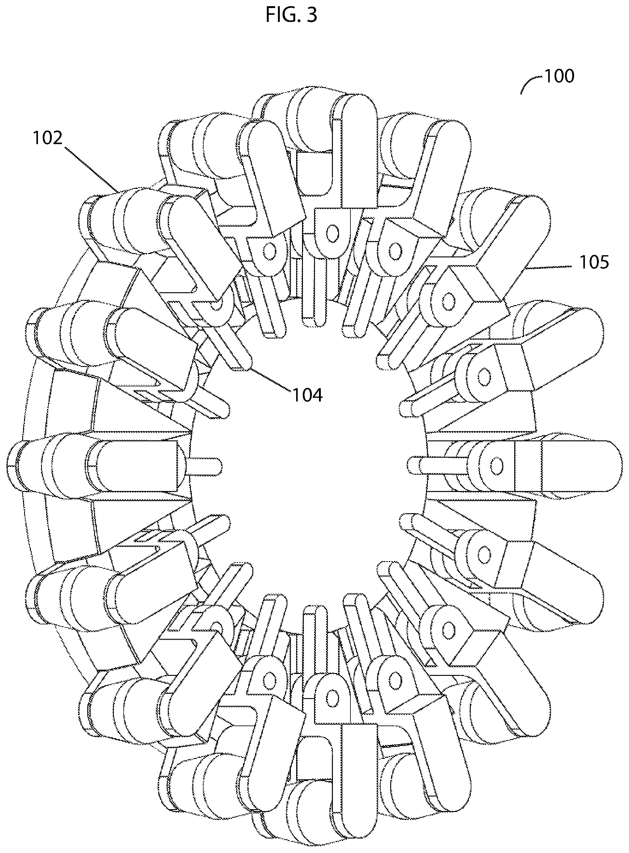
FIG. 3 illustrates a cutaway of an example of an expandable wheel, embodying features of the present invention.
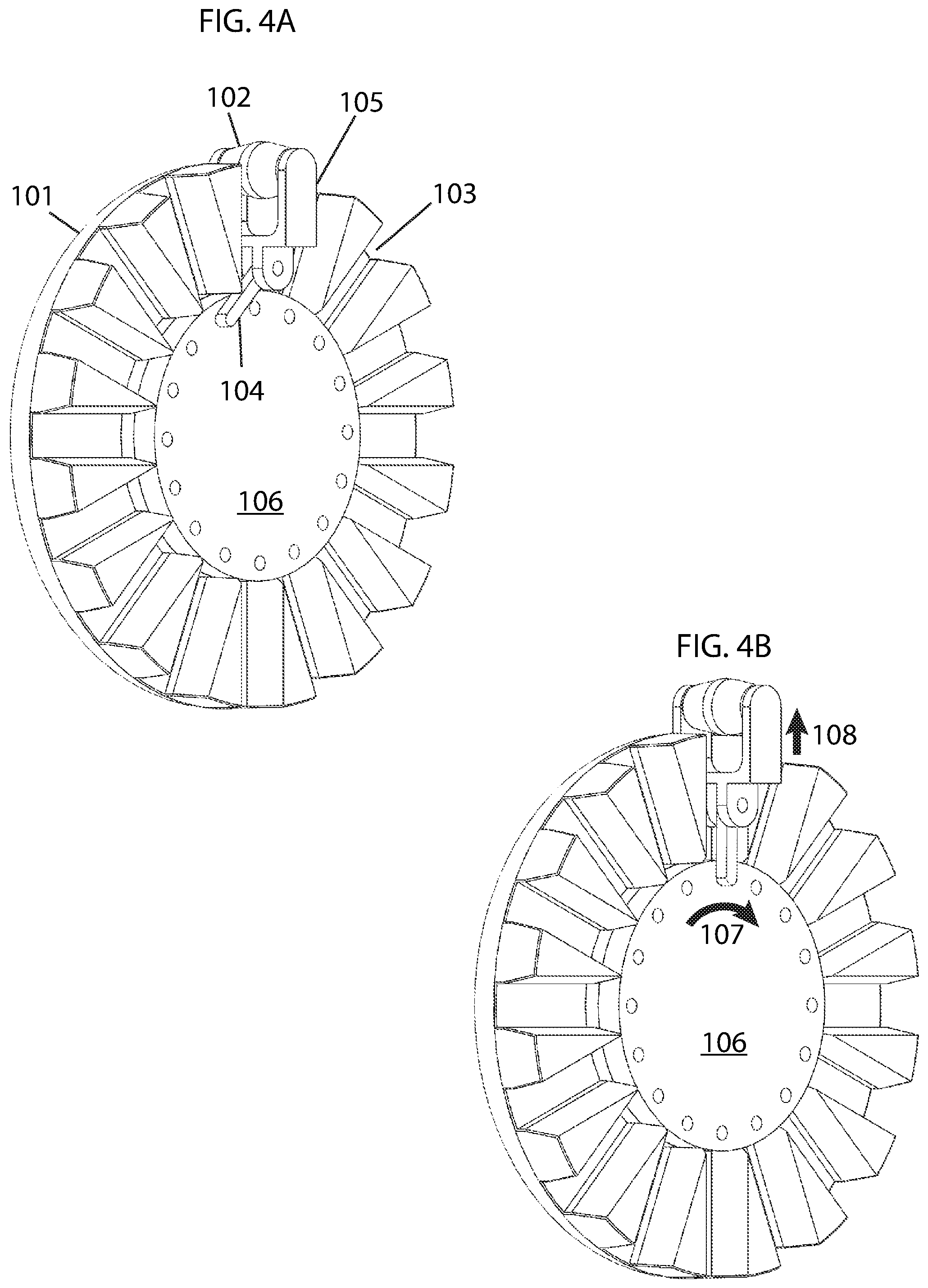
FIG. 4A illustrates a cutaway of an example of an expandable wheel in a contracted position, embodying features of the present invention.
FIG. 4B illustrates a cutaway of an example of an expandable wheel in an expanded position, embodying features of the present invention.
FIG. 5A illustrates a side elevation view of an example of a robotic floor cleaning device with expandable wheels in a contracted position, embodying features of the present invention.
FIG. 5B illustrates a side elevation view of an example of a robotic floor cleaning device with expandable wheels in an expanded position embodying features of the present invention.
DETAILED DESCRIPTION OF SOME EMBODIMENTS
The present inventions will now be described in detail with reference to a few embodiments thereof as illustrated in the accompanying drawings. In the following description, numerous specific details are set forth in order to provide a thorough understanding of the present inventions. It will be apparent, however, to one skilled in the art, that the present invention may be practiced without some or all of these specific details. In other instances, well known process steps and/or structures have not been described in detail in order to not unnecessarily obscure the present invention. Further, it should be emphasized that several inventive techniques are described, and embodiments are not limited to systems implanting all of those techniques, as various cost and engineering trade-offs may warrant systems that only afford a subset of the benefits described herein or that will be apparent to one of ordinary skill in the art.
The present invention proposes a robotic floor cleaning device with expandable wheels. The robotic floor cleaning device comprises a shell, a chassis, a set of expandable wheels; at least one motor connected to the wheels for moving the robotic floor cleaning device on a surface; a control unit to control movement of the device, and a means for cleaning a work surface.
Any number of wheels may comprise the set of expandable wheels.
Referring to FIG. 1, a perspective view of an example of an expandable wheel 100 is illustrated in a contracted position. As can be seen, each roller 102 protrudes slightly through an aperture 103. Again, the main housing 101 of the wheel remains fixed when the rollers are pushed outward through the apertures to create a larger wheel circumference.
Referring to FIG. 2, an example of expandable wheel 100 is illustrated in an expanded position. As can be seen, the main housing 101 of the wheel has remained in a fixed position in relation to the rollers 102, which have been pushed radially outward from the center of the wheel through the apertures 103 via spokes within the wheel (not shown). Each roller is mounted at the end of a link member so as to be rotatable around an axial of the roller.
Referring to FIG. 3, an example of a cutaway of the wheel 100 is illustrated to show the interior parts. Each roller 102 is mounted on the end of a pivoting linkage 105 connected to a spoke 104. The inner ends of the spokes are connected to an inner shaft (not shown) that is rotated within the wheel to push the spokes in or out. In the preferred embodiment, the rollers are rotatable around an axial.
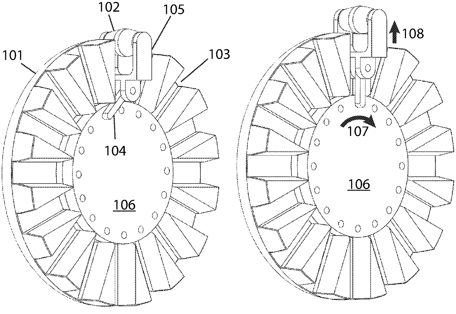
Referring briefly to both FIGS. 4A and 4B, examples of cutaway views of the wheel are illustrated to more clearly portray the internal parts. In both drawings, a singular spoke, linkage, and roller is illustrated in order to portray the parts more clearly, however, in practice, each of the apertures 103 would contain a spoke, linkage and roller. Referring to FIG. 4A, the spoke 104, linkage 105 and roller 102 are in a contracted position. The spoke 104 is mounted pivotally by a first end to an inner shaft 106, which is co-centered and coupled within the main housing 101. The inner shaft is coupled with the main housing in such a way as to allow rotation of the inner shaft with relation to the main housing. Such rotation causes the spokes together with the pivoting linkages to work as a crank mechanism and translate the relative rotation of the two parts to a linear movement of the roller outward from the center of the wheel, the aperture working as a guide. As shown in FIG. 4B, this movement results in each spoke, linkage, and roller group to be extended in a radially outward direction 108. When the inner shaft 106 is rotated in direction 107 and goes from the position shown in FIG. 4A to the position shown in FIG. 4B wherein each spoke is parallel with the corresponding aperture, the spokes and linkages are pushed outward, causing the rollers to protrude further through the apertures.
In some embodiments, when the inner shaft and main housing are rotated in the same direction and at the same rate, the wheel simply turns as a normal wheel and the rollers, spokes and linkages are not pushed outward or inward. In some embodiments, it is when the inner shaft is rotated in an opposite direction of the main housing that the rollers, spokes and linkages are pushed outward or inward.
Referring to FIG. 5A, a side elevation view of an example of a robotic floor cleaning device 500 with expanding wheels 100 in their contracted position is illustrated. In this example, the wheels 100 are in a contracted position and thus have their smallest possible circumference. This maintains a smallest possible distance 501 to the work surface 502, which may aide the device in driving under furniture and picking up debris.
Referring to FIG. 5B, an example of a side elevation view of the robotic floor cleaning device 500 with expanding wheels 100 in an expanded position is illustrated. In this example, the wheels 100 are in an expanded position and thus have their greatest possible circumference. This maintains a greatest possible distance 503 to the work surface 502, which may aide the device in driving over obstacles or various work surfaces.
In some embodiments, the invention further comprises sensors to detect conditions when the wheels should be expanded. For example, a sensor monitoring tension on wheels may cause the wheels to expand when more than a predetermined amount of tension is detected. Similarly, a sensor monitoring rate of rotation of a wheel may cause the wheels to expand when it is determined that rotation is not concurrent with motor power. It will be obvious to one skilled in the art that the disclosed invention can benefit from any kind of sensing mechanism to detect tension etc.
* * * * *
D00000
D00001
D00002
D00003
D00004
D00005
XML
uspto.report is an independent third-party trademark research tool that is not affiliated, endorsed, or sponsored by the United States Patent and Trademark Office (USPTO) or any other governmental organization. The information provided by uspto.report is based on publicly available data at the time of writing and is intended for informational purposes only.
While we strive to provide accurate and up-to-date information, we do not guarantee the accuracy, completeness, reliability, or suitability of the information displayed on this site. The use of this site is at your own risk. Any reliance you place on such information is therefore strictly at your own risk.
All official trademark data, including owner information, should be verified by visiting the official USPTO website at www.uspto.gov. This site is not intended to replace professional legal advice and should not be used as a substitute for consulting with a legal professional who is knowledgeable about trademark law.