Pedal unit for a vehicle, particularly a utility vehicle
Rizzi , et al. February 2, 2
U.S. patent number 10,908,633 [Application Number 16/238,669] was granted by the patent office on 2021-02-02 for pedal unit for a vehicle, particularly a utility vehicle. This patent grant is currently assigned to KNORR-BREMSE Systeme fuer Nutzfahrzeuge GmbH. The grantee listed for this patent is KNORR-BREMSE Systeme fuer Nutzfahrzeuge GmbH. Invention is credited to Giorgio Andreetta, Stefano Rizzi.


| United States Patent | 10,908,633 |
| Rizzi , et al. | February 2, 2021 |
Pedal unit for a vehicle, particularly a utility vehicle
Abstract
A pedal unit for a vehicle, particularly a utility vehicle, has at least one pedal shaft, at least one control cam, at least one pedal and at least one lever arm. The pedal is rigidly secured to the pedal shaft by the lever arm. The control cam is also rigidly secured to the pedal shaft.
| Inventors: | Rizzi; Stefano (Lissone, IT), Andreetta; Giorgio (Biassono, IT) | ||||||||||
|---|---|---|---|---|---|---|---|---|---|---|---|
| Applicant: |
|
||||||||||
| Assignee: | KNORR-BREMSE Systeme fuer
Nutzfahrzeuge GmbH (Munich, DE) |
||||||||||
| Family ID: | 1000005336344 | ||||||||||
| Appl. No.: | 16/238,669 | ||||||||||
| Filed: | January 3, 2019 |
Prior Publication Data
| Document Identifier | Publication Date | |
|---|---|---|
| US 20190138045 A1 | May 9, 2019 | |
Related U.S. Patent Documents
| Application Number | Filing Date | Patent Number | Issue Date | ||
|---|---|---|---|---|---|
| PCT/EP2017/065042 | Jun 20, 2017 | ||||
Foreign Application Priority Data
| Jul 4, 2016 [DE] | 10 2016 112 188 | |||
| Current U.S. Class: | 1/1 |
| Current CPC Class: | G05G 1/46 (20130101); B60K 26/02 (20130101); B60T 7/06 (20130101); B60K 23/02 (20130101); G05G 1/44 (20130101); B60T 7/04 (20130101); B60Y 2200/14 (20130101); B60Y 2304/07 (20130101) |
| Current International Class: | G05G 1/44 (20080401); B60K 23/02 (20060101); B60K 26/02 (20060101); B60T 7/06 (20060101); G05G 1/46 (20080401); B60T 7/04 (20060101) |
References Cited [Referenced By]
U.S. Patent Documents
| 4109529 | August 1978 | Niklaus |
| 5078024 | January 1992 | Cicotte |
| 5497677 | March 1996 | Baumann et al. |
| 6070489 | June 2000 | Ananthasivan |
| 6446525 | September 2002 | Borchers |
| 6612200 | September 2003 | Rixon |
| 2002/0184749 | December 2002 | Burgstaler et al. |
| 2006/0248978 | November 2006 | Prat Terradas |
| 2007/0209471 | September 2007 | Nunez |
| 2009/0071285 | March 2009 | Lauderbaugh |
| 2018/0170325 | June 2018 | Christoff |
| 2019/0004560 | January 2019 | Strom |
| 1408575 | Apr 2003 | CN | |||
| 104272212 | Jan 2015 | CN | |||
| 207842910 | Sep 2018 | CN | |||
| 2 138 952 | Feb 1973 | DE | |||
| 100 40 043 | Aug 2001 | DE | |||
| 699 01 991 | Apr 2003 | DE | |||
| 102 32 212 | Jan 2004 | DE | |||
| 10 2004 018 266 | Nov 2005 | DE | |||
| 10 2012 010 674 | Dec 2013 | DE | |||
| 20 2014 101 559 | Jun 2014 | DE | |||
| 0 659 606 | Jun 1995 | EP | |||
| 0 788 931 | Aug 1997 | EP | |||
| 1 749 732 | Feb 2007 | EP | |||
| 1 365 202 | Aug 1974 | GB | |||
| 8-30346 | Feb 1996 | JP | |||
| 2000-148271 | May 2000 | JP | |||
| 2002-512392 | Apr 2002 | JP | |||
| 2009-169818 | Jul 2009 | JP | |||
Other References
|
Wikipedia webpage (https://en.wikipedia.org/wiki/Oval), section "In common speech" (Year: 2020). cited by examiner . International Search Report (PCT/ISA/210) issued in PCT Application No. PCT/EP2017/065042 dated Aug. 28, 2017 with English translation (six (6) pages). cited by applicant . German-language Written Opinion (PCT/ISA/237) issued in PCT Application No. PCT/EP2017/065042 dated Aug. 28, 2017 (seven (7) pages). cited by applicant . German-language Office Action issued in counterpart German Application No. 10 2016 112 188.6 dated Jun. 24, 2017 (seven (7) pages). cited by applicant . International Preliminary Report on Patentability (PCT/IB/326 & PCT/IB/373) issued in PCT Application No. PCT/EP2017/065042 dated Jan. 17, 2019, including English translation of document C2 (German-language Written Opinion (PCT/ISA/237)) previously filed on Jan. 3, 2019 (nine pages). cited by applicant . Japanese Office Action issued in Japanese counterpart application No. 2018-568765 dated Sep. 30, 2019, with partial English translation (Six (6) pages). cited by applicant . Japanese Office Action issued in Japanese application No. 2018-568765 dated May 28, 2020, with partial English translation (Eight (8) pages). cited by applicant . Chinese Office Action issued in Chinese application No. 201780041960.4 dated Aug. 4, 2020, with partial English translation (Ten (10) pages). cited by applicant. |
Primary Examiner: Gokhale; Prasad V
Attorney, Agent or Firm: Crowell & Moring LLP
Parent Case Text
CROSS REFERENCE TO RELATED APPLICATIONS
This application is a continuation of PCT International Application No. PCT/EP2017/065042, filed Jun. 20, 2017, which claims priority under 35 U.S.C. .sctn. 119 from German Patent Application No. 10 2016 112 188.6, filed Jul. 4, 2016, the entire disclosures of which are herein expressly incorporated by reference.
Claims
What is claimed is:
1. A pedal unit for a vehicle, comprising: at least one pedal shaft; at least one control cam; at least one pedal and at least one lever arm, wherein the pedal is firmly secured by way of the lever arm to the pedal shaft and wherein the control cam is firmly secured to the pedal shaft; and a pedal plate with a first shaft mount and a second shaft mount, wherein the pedal shaft is mounted by way of the first and second shaft mounts on the pedal plate, wherein the first shaft mount has a first opening with a cross section that is larger than the cross section of a first pedal shaft bearing section of the pedal shaft, by which the fully assembled pedal shaft is introducible into the first shaft mount during an assembly process, and wherein the cross section of the first opening is oval, wherein the second shaft mount comprises a second opening which forms a fit with a second pedal shaft bearing section of the pedal shaft and wherein the fit is formed by a bore with a circular cross section.
2. The pedal unit as claimed in claim 1, further comprising: a bearing bushing arranged at one end of the pedal shaft.
3. The pedal unit as claimed in claim 1, wherein the pedal shaft with the first pedal shaft bearing section is introducible at a slant into the first opening.
4. The pedal unit as claimed in claim 3, wherein the first pedal shaft bearing section of the pedal shaft in a mounted condition of the pedal unit is held by an insert bushing in the first opening of the first shaft mount.
5. The pedal unit as claimed in claim 1, wherein the first pedal shaft bearing section of the pedal shaft in a mounted condition of the pedal unit is held by an insert bushing in the first opening of the first shaft mount.
6. The pedal unit as claimed in claim 1, wherein the pedal unit is a utility vehicle pedal unit.
Description
BACKGROUND AND SUMMARY OF THE INVENTION
The present invention relates to a pedal unit for a vehicle, especially a utility vehicle, with at least one pedal shaft, at least one control cam, at least one pedal and at least one lever arm.
Pedal units for vehicles are already known from the prior art in connection with driver work stations for utility vehicles.
Thus, for example, EP 1 749 732 A1 discloses a driver work station for a utility vehicle, wherein the driver work station comprises multiple individual components and the utility vehicle has a module opening on the vehicle frame.
From EP 0 659 606 A1 there is known a gas pedal mechanism for a motor vehicle, wherein a pedal plate is pivotably mounted on a pedal holder in the form of a housing and is connected to a pedal plate connected actuating device, namely a pedal.
DE 20 2014 101 559 U1 discloses a foot pedal for activating a machine.
Pedal units for vehicles, especially for utility vehicles, if they are mechanically designed, might have a very complex and also very bulky mechanism, which may make the assembly process difficult. This may also result in such a pedal unit requiring comparatively large structural space.
Therefore, the problem which the present invention proposes to solve is to develop a pedal unit of the kind mentioned at the outset in advantageous manner, especially so that the pedal unit can be mounted more easily.
This problem is solved according to the invention by a pedal unit for a vehicle with at least one pedal shaft, at least one control cam, at least one pedal and at least one lever arm, wherein the pedal is firmly secured by way of the lever arm to the pedal shaft and wherein the control cam is also firmly secured to the pedal shaft.
The invention is based on the fundamental notion that the pedal unit is designed as an integrated component, so that it can be installed with few manual operations. This is accomplished in that the components of pedal, pedal shaft, control cam and lever arm are firmly secured to the pedal shaft. The fact that the components of pedal, pedal shaft, control cam and lever arm are firmly secured to the pedal shaft makes it easier to handle this portion of the pedal unit, because now it is not necessary to assemble and install multiple parts, but rather only one part needs to be mounted accordingly.
The vehicle may be, for example, a utility vehicle, such as a truck or the like.
Furthermore, a bearing bushing is arranged at one end of the pedal shaft. By means of the bearing bushing, the corresponding end of the pedal shaft can be mounted, especially rotatably mounted, to avoid a costly machining of the pedal shaft. Thus, for example, it is possible that the pedal shaft or corresponding mating pieces need not be provided with fits of narrow tolerance in a costly manner, since this can be accomplished by means of bearing bushings and thus by standard parts, for example. In this way, the manufacturing costs can be reduced.
Moreover, the pedal unit further comprises a pedal plate with a first shaft mount and a second shaft mount, wherein the pedal shaft is secured by way of the first and second shaft mount on the pedal plate. By means of the shaft mounts, a supporting of the pedal shaft is possible. In particular, the control cam is actuated by treading on the pedal, so that the lever arm and control cam are pivoted, namely about the longitudinal axis of the pedal shaft, which is rotatably mounted in the first shaft mount and second shaft mount.
It may be provided that the first shaft mount has an opening with a cross section that is larger than the cross section of a first pedal shaft bearing section of the pedal shaft, by which it is introduced into the first shaft mount during the assembly process. This enables a simple installation of the fully assembled pedal shaft, since in this way the pedal shaft can be inserted into the opening of the first shaft mount with an angle of attack or engagement greater than zero.
The cross section of the opening of the first shaft mount may be oval and/or oblong. Furthermore, alternatively or additionally, it may be provided that the pedal shaft with the first pedal shaft bearing section can be introduced at a slant into the opening. In this way, it becomes possible to place the pedal shaft between the first shaft mount and the second shaft mount and to introduce the pedal shaft at first into the opening of the first shaft mount and then to be able to orient it in the opening of the first shaft mount by swiveling it such that it can also be inserted into the second shaft mount.
The first pedal shaft bearing section of the pedal shaft in the mounted condition of the pedal unit can be held by way of an insert bushing in the opening of the first shaft mount. In this way, it becomes easily possible to even out accordingly the different cross sections of openings of the first shaft mount and of the first pedal shaft bearing section of the pedal shaft, so that the pedal shaft is advisedly rotatably mounted in the first shaft mount.
Furthermore, it may be provided that the second shaft mount comprises an opening, which forms a fit with a second pedal shaft bearing section of the pedal shaft. It is also contemplated for the fit to be formed such that the bearing bushing can be installed here. Basically, however, it is also possible not to install any bearing bushing at all in the opening of the second shaft mount and instead for the pedal shaft to rotate directly in the opening.
In particular, it may be provided that the fit is formed by a bore, especially a bore with a circular cross section. In this way, an easy fabrication is provided, at the same time as an efficient assembly process and the desired functionality.
Other objects, advantages and novel features of the present invention will become apparent from the following detailed description of one or more preferred embodiments when considered in conjunction with the accompanying drawings.
BRIEF DESCRIPTION OF THE DRAWINGS
FIG. 1 is a perspective view of an exemplary embodiment of a pedal unit for a vehicle according to the invention.
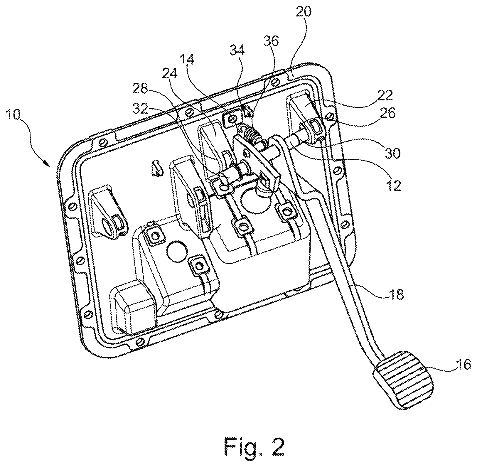
FIG. 2 is a perspective view of the assembly process for the pedal unit of FIG. 1.
FIG. 3 is a further perspective view of the assembly process for the pedal unit of FIG. 1.
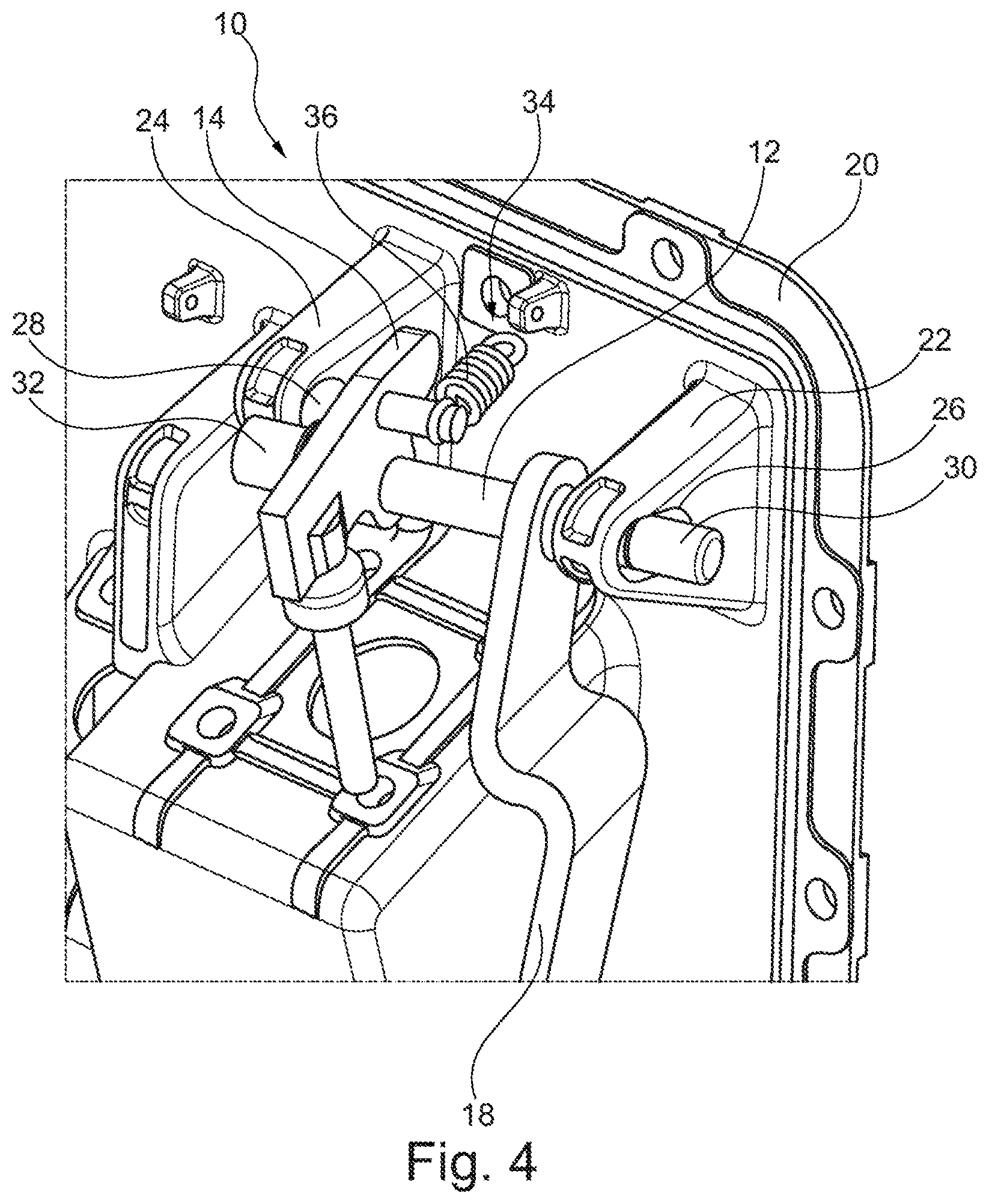
FIG. 4 is a further perspective view of the assembly process for the pedal unit of FIG. 1.
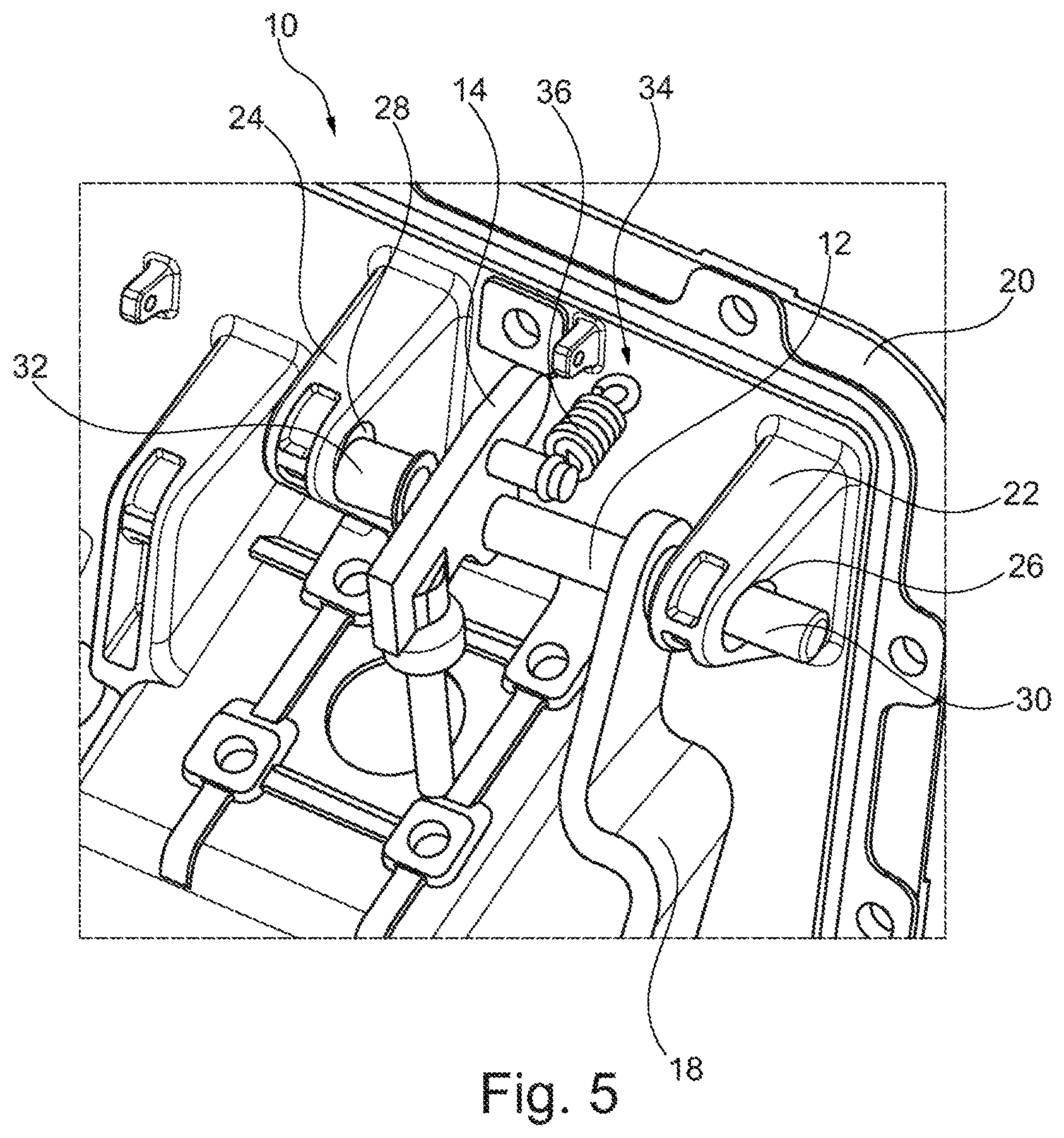
FIG. 5 is a further perspective view of the assembly process for the pedal unit of FIG. 1.
FIG. 6 is a further perspective view of the assembly process for the pedal unit of FIG. 1.
DETAILED DESCRIPTION OF THE DRAWINGS
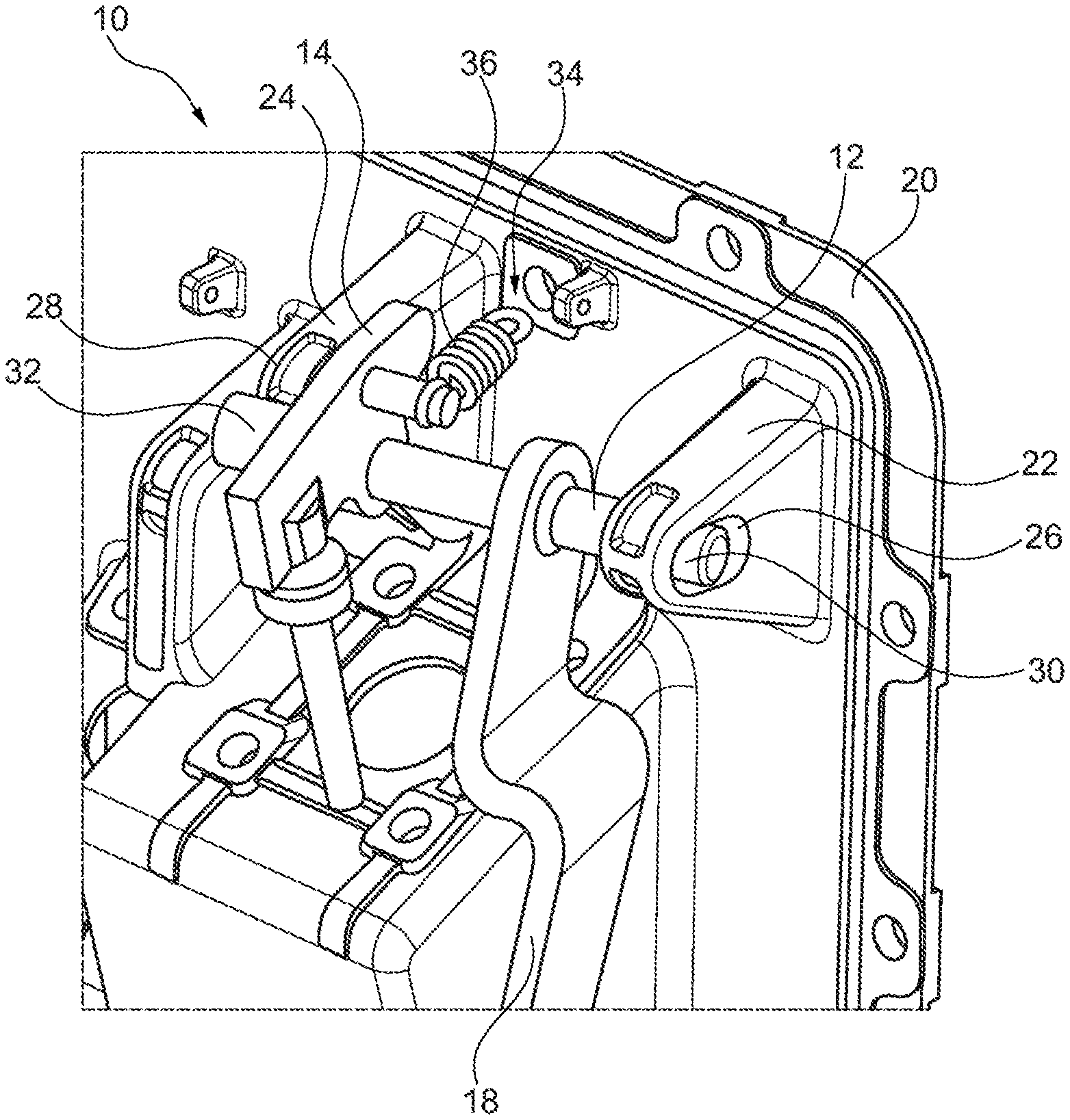
FIG. 1 shows in perspective view an exemplary embodiment of a pedal unit 10 according to the invention for a vehicle, here, for a utility vehicle.
The pedal unit 10 includes a pedal shaft 12, a control cam 14, a pedal 16 (see FIG. 2) and a lever arm 18.
Furthermore, the pedal unit 10 includes a pedal plate 20, having a first shaft mount 22 and a second shaft mount 24.
The first shaft mount 22 has a first opening 26 and the second shaft mount 24 has a second opening 28.
Secured firmly on the pedal shaft 12 are the pedal 16 by way of a lever arm 18 and the control cam 14.
The pedal 16 is secured to the lever arm 18 by means of a suitable firm connection on the lever arm 18, e.g. by means of a screw connection, a plug-in connection, or the like.
The lever arm 18 is pressed onto the pedal shaft 12 and then welded at one end to the fastening site. A two-ended weld seam is also contemplated. Alternatively, screw connections, solder connections, or the like, are also possible.
The control cam 14 is fastened similar to the lever arm 18 on the pedal shaft 12. Here as well, the control cam 14 is welded to the pedal shaft 12 at the fastening site by use of a single-ended weld seam. A two-ended weld seam is also usable. Alternatively, screw connections, solder connections, or the like, are also possible.
The pedal shaft 12 is provided at both ends with a first pedal shaft bearing section 30 and a second pedal shaft bearing section 32.
The first pedal shaft bearing section 30 is provided for inserting into the opening 26 of the first shaft mount 22.
The second pedal shaft bearing section 32 is provided for inserting into the opening 28 of the second shaft mount 24.
Furthermore, a restoring element 34 is provided, by which the pedal unit can be returned to a neutral position when the pedal 16 is no longer under load.
The restoring element 34 has a return spring 36.
The return spring 36 engages on the one hand with the pedal plate 20 and on the other hand with the control cam 14.
FIGS. 2 to 6 show the assembly process of the pedal shaft 12 with the control cam 14 and pedal 16 with lever arm 18 firmly fastened to it.
First of all, the pedal shaft 12 is introduced at a slant into the opening 26 of the first shaft mount 22, i.e., with an angle of attack greater than zero, and specifically far enough so that the second pedal shaft bearing section 32 of the pedal shaft 12 at the opposite end of the first pedal shaft bearing section 30 of the pedal shaft 12 is situated between the first shaft mount 22 and the second shaft mount 24.
The second pedal shaft bearing section 32 is then introduced into the opening 28 of the second shaft mount 24.
Both the first pedal shaft bearing section 30 and the second pedal shaft bearing section 32 are then rotatably mounted and fixed with the bearing bushings in the respective openings 26 and 28.
Here, the bearing bushing for the first pedal shaft bearing section 30 and the opening 26 of the first shaft mount 22 are adapted by their outer contour to the inner cross section of the opening 26 of the first shaft mount 22, so that the pedal shaft bearing section 30 is also mounted there in an accordingly defined rotatable manner.
LIST OF REFERENCE NUMBERS
10 Pedal unit 12 Pedal shaft 14 Control cam 16 Pedal 18 Lever arm 20 Pedal plate 22 First shaft mount 24 Second shaft mount 26 First opening 28 Second opening 30 First pedal shaft bearing section 32 Second pedal shaft bearing section 34 Restoring element 36 Return spring
The foregoing disclosure has been set forth merely to illustrate the invention and is not intended to be limiting. Since modifications of the disclosed embodiments incorporating the spirit and substance of the invention may occur to persons skilled in the art, the invention should be construed to include everything within the scope of the appended claims and equivalents thereof.
* * * * *
References
D00000
D00001
D00002
D00003
D00004
D00005
D00006
XML
uspto.report is an independent third-party trademark research tool that is not affiliated, endorsed, or sponsored by the United States Patent and Trademark Office (USPTO) or any other governmental organization. The information provided by uspto.report is based on publicly available data at the time of writing and is intended for informational purposes only.
While we strive to provide accurate and up-to-date information, we do not guarantee the accuracy, completeness, reliability, or suitability of the information displayed on this site. The use of this site is at your own risk. Any reliance you place on such information is therefore strictly at your own risk.
All official trademark data, including owner information, should be verified by visiting the official USPTO website at www.uspto.gov. This site is not intended to replace professional legal advice and should not be used as a substitute for consulting with a legal professional who is knowledgeable about trademark law.