Cartridge box for ammunition belt
Roggen , et al. February 2, 2
U.S. patent number 10,907,917 [Application Number 16/608,746] was granted by the patent office on 2021-02-02 for cartridge box for ammunition belt. This patent grant is currently assigned to FN Herstal S.A.. The grantee listed for this patent is FN Herstal S.A.. Invention is credited to Yannick Bailly, Frederic Jadin, Olivier Jaspart, Patrick Roggen.

| United States Patent | 10,907,917 |
| Roggen , et al. | February 2, 2021 |
Cartridge box for ammunition belt
Abstract
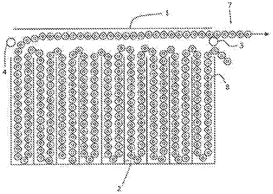
The present invention relates to a cartridge box comprising: --a box (1) comprising an intake (5) and an outlet (6), the outlet (6) being placed under the intake (5) and separated from same by a guide roller (3); --a plurality of compartments (9) separated by partitions (2); --a belt (7) of cartridges (8), said cartridge belt crossing the intake (5), then folding into the compartments (9), from the compartment (9) closest to the intake (5) to the compartment that is furthest away, and then crossing the outlet (6), above the guide roller (3).
| Inventors: | Roggen; Patrick (Herstal, BE), Bailly; Yannick (Herstal, BE), Jadin; Frederic (Herstal, BE), Jaspart; Olivier (Herstal, BE) | ||||||||||
|---|---|---|---|---|---|---|---|---|---|---|---|
| Applicant: |
|
||||||||||
| Assignee: | FN Herstal S.A. (Herstal,
BE) |
||||||||||
| Family ID: | 1000005335712 | ||||||||||
| Appl. No.: | 16/608,746 | ||||||||||
| Filed: | April 24, 2018 | ||||||||||
| PCT Filed: | April 24, 2018 | ||||||||||
| PCT No.: | PCT/EP2018/060424 | ||||||||||
| 371(c)(1),(2),(4) Date: | October 25, 2019 | ||||||||||
| PCT Pub. No.: | WO2018/197456 | ||||||||||
| PCT Pub. Date: | November 01, 2018 |
Prior Publication Data
| Document Identifier | Publication Date | |
|---|---|---|
| US 20200200497 A1 | Jun 25, 2020 | |
Foreign Application Priority Data
| Apr 25, 2017 [BE] | 2017/5293 | |||
| Current U.S. Class: | 1/1 |
| Current CPC Class: | F41A 9/79 (20130101) |
| Current International Class: | F41A 9/79 (20060101) |
References Cited [Referenced By]
U.S. Patent Documents
| 1790867 | February 1931 | Jervey |
| 1901868 | March 1933 | Dabrasky |
| 2110160 | March 1938 | Larsson |
| 2339869 | January 1944 | Martin |
| 2388958 | November 1945 | Murphy |
| 2398263 | April 1946 | Trimbach |
| 2452545 | November 1948 | Broga |
| 2470475 | May 1949 | Diaper |
| 2573774 | November 1951 | Sandberg |
| 2710561 | June 1955 | Dowd |
| 2811084 | October 1957 | Cook |
| 2874615 | February 1959 | Kravik |
| 2889751 | June 1959 | Bilek |
| 3461774 | August 1969 | Maurer |
| 4009638 | March 1977 | Ramseyer |
| 4393746 | July 1983 | Rocha |
| 4494440 | January 1985 | Koine |
| 4573395 | March 1986 | Stoner |
| 4610191 | September 1986 | Schmid |
| 4681019 | July 1987 | Brandl |
| 4876940 | October 1989 | Aloi |
| 4882972 | November 1989 | Raymond |
| 4974490 | December 1990 | Austin |
| 5115713 | May 1992 | Muller |
| 5149909 | September 1992 | Hagen |
| 6164180 | December 2000 | Sulm |
| 6389948 | May 2002 | Beckmann |
| 7913610 | March 2011 | Ulveraker |
| 8763511 | July 2014 | Schvartz |
| 10203175 | February 2019 | Lung |
| 2010/0011946 | January 2010 | Ulveraker |
| 0077084 | Apr 1984 | CH | |||
| 0343825 | Nov 1989 | GB | |||
Attorney, Agent or Firm: Leydig, Voit & Mayer, Ltd. Gray; Gerald T.
Claims
The invention claimed is:
1. An assembly of at least two cartridge boxes, each of the at least two cartridge boxes comprising: a box comprising an inlet and an outlet, the outlet being positioned under the inlet and being separated therefrom by a turn roller; and a plurality of compartments separated by partitions; and the assembly further comprising: a belt of cartridges, said belt of cartridges passing through the inlet, then being folded up in the plurality of compartments, from a compartment closest to the inlet to a farthest away compartment, the belt of cartridges then passing through the outlet, over the top of the turn roller; wherein the belt of cartridges passing through the outlet of a first cartridge box enters the inlet of a second cartridge box.
2. The assembly of claim 1, wherein each of the at least two cartridge boxes comprises a removable cover for easy loading of the belt of cartridges.
3. The assembly of claim 1, wherein a permanent magnet is disposed at a bottom of each compartment of the plurality of compartments of each of the at least two cartridge boxes, each permanent magnet enabling the belt of cartridges to be secured in the compartment regardless of the position of the box.
4. The assembly of claim 1 wherein each cartridge box of the at least two cartridge boxes comprises a second inlet and a second outlet separated by a second turn roller on an opposite face of the box.
5. The assembly of claim 1, wherein in each cartridge box of the at least two cartridge boxes the partitions of the plurality of compartments comprise, on an opposite side of the cartridge box from the inlet and the outlet, cells for keeping a belt strand static during an unloading of the compartment.
6. A cartridge box comprising: a box comprising an inlet and an outlet, the outlet being positioned under the inlet and being separated therefrom by a turn roller; a plurality of compartments separated by partitions; and a belt of cartridges, said belt of cartridges passing through the inlet, then being folded up in the plurality of compartments, from a compartment closest to the inlet to a farthest away compartment, the belt of cartridges then passing through the outlet, over the top of the turn roller; wherein a permanent magnet is disposed at a bottom of each compartment of the plurality of compartments, each permanent magnet enabling the belt of cartridges to be secured in the compartment regardless of the position of the box.
7. A cartridge box comprising: a box comprising an inlet and an outlet, the outlet being positioned under the inlet and being separated therefrom by a turn roller; a plurality of compartments separated by partitions; a belt of cartridges, said belt of cartridges passing through the inlet, then being folded up in the plurality of compartments, from a compartment closest to the inlet to a farthest away compartment, the belt of cartridges then passing through the outlet, over the top of the turn roller; and a second inlet and a second outlet separated by a second turn roller on an opposite face of the box.
Description
SUBJECT OF THE INVENTION
The present invention relates to a cartridge box for ammunition in the form of a belt, comprising cartridges joined together by links.
PRIOR ART
A person skilled in the art is familiar with using compartment boxes for storing and delivering to an automatic weapon cartridges that are joined together in the form of ammunition belts by links. The document U.S. Pat. No. 2,811,084 describes for example such a box.
These prior art boxes have a number of limitations, however: the number of cartridges available is limited by the size of a single box, the position of the box is determined a priori and there is no flexibility with respect to this position.
However, these cartridge boxes are mainly used in applications on-board craft such as the sides of helicopters, for which there is no possibility of reloading in flight. Moreover, on this type of vehicle, the shape of the available space for the cartridge boxes is defined more by aerodynamic or balance-related constraints than by the practical aspect of storing ammunition. Therefore, the possibility of distributing the ammunition over several smaller boxes represents a key advantage. These boxes also have to be able to be disposed in any position in order to be adaptable to several types of weaponry for standardization purposes.
AIMS OF THE INVENTION
The present invention has the aim of providing a cartridge belt for ammunition in the form of a belt that exhibits the best flexibility in terms of positioning and capacity.
SUMMARY OF THE INVENTION
The present invention relates to a cartridge box comprising: a box comprising an inlet and an outlet, the outlet being positioned under the inlet and being separated therefrom by a turn roller; a plurality of compartments separated by partitions; a belt of cartridges, said cartridge belt passing through the inlet, then being folded up in the compartments, from the compartment closest to the inlet to the farthest away compartment, the belt then passing through the outlet, over the top of the turn roller.
Advantageously, the cartridge box of the invention comprises a second inlet and a second outlet separated by a second turn roller on the opposite face of the box such that it is possible to position the inlet and the outlet equally on the left-hand side or on the right-hand side of the cartridge box.
Preferably, the cartridge box of the invention comprises a removable cover for easily reversing the outlet side of the belt.
Preferably, a permanent magnet is disposed at the bottom of each compartment, each magnet making it possible to keep the cartridge belt in the compartment regardless of the position of the box.
When the cartridge box is preferably used with the inlet/outlet at the bottom of the box (upside down), the face of the walls of the compartments that is on the opposite side from the inlet/outlet side may comprise cells that help to keep the belt static.
The present invention also relates to an assembly of at least two cartridge boxes according to the invention, wherein the cartridge belt exiting the first box is connected to the belt entering the second box.
BRIEF DESCRIPTION OF THE FIGURES
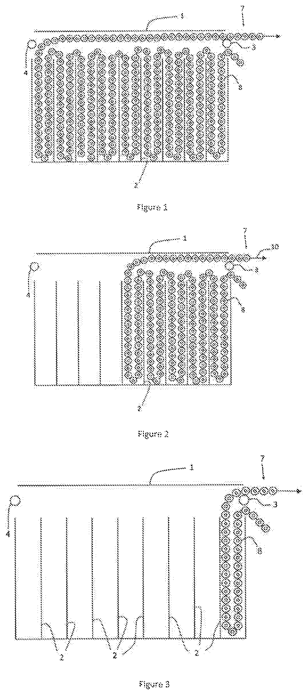
FIG. 1 shows a filled cartridge box according to the invention.
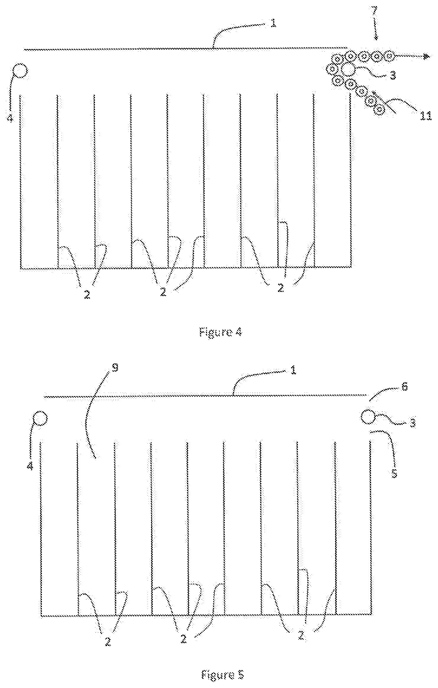
FIGS. 2 to 5 show the successive steps of emptying the cartridge box in FIG. 1.
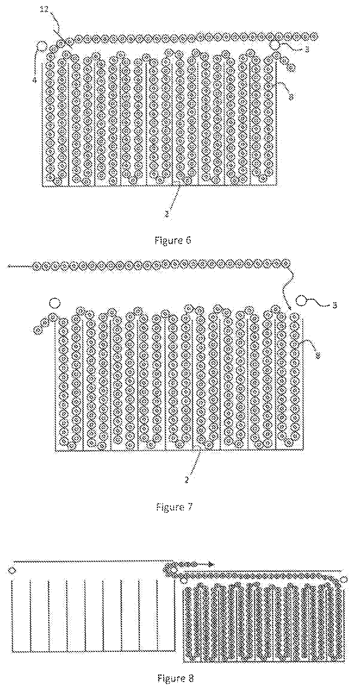
FIG. 6 show a cartridge box according to the invention, with the cover open in order to change the inlet/outlet side.
FIG. 7 shows the process of changing the inlet/outlet side.
FIG. 8 shows two cartridge boxes according to the invention disposed in series.
FIG. 9 shows a preferred embodiment of the invention, comprising magnets at the bottom of the compartments, the cartridge box being disposed "upside down".
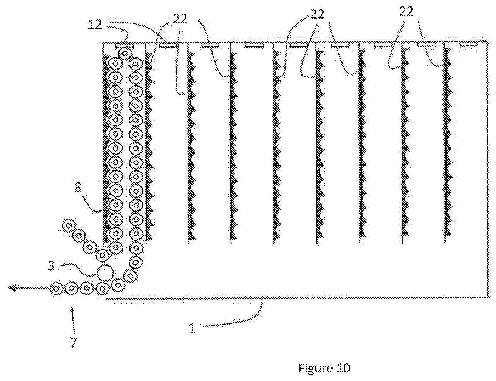
FIG. 10 shows another cartridge box according to the invention.
DETAILED DESCRIPTION OF THE INVENTION
The present invention relates to a cartridge box for ammunition in the form of a belt having links for connecting several boxes in series, such that it is possible to have as much space available as possible for feeding a machine gun or cannon, mainly for on-board applications.
To this end, the cartridge box of the invention comprises an inlet 5 and an outlet 6 separated by a turn roller 3, the inlet 5 being positioned above the outlet, on the same side of the box. The term "above" means here the top of the cartridge box positioned in the position intended for loading the box. In fact, it will be seen below that, according to preferred embodiments of the invention, the box can be positioned, in use, in virtually any position.
In order to make it easier to position the belt and easily unload the latter, the ammunition box of the invention comprises a plurality of compartments 9 separated by vertical partitions 2.
The belt 7 is initially positioned in a zigzag in the compartments 9, from the compartment close to the inlet 5 to the opposite side. The belt 7 is then folded up towards the outlet. This arrangement allows the belt 7 to slide over the top of the filled compartments 9, sliding over the cartridges, this avoiding a situation in which the links catch on the tops of the walls 2 of the empty compartments 9.
Advantageously, the bottom of the compartments 9 comprises a permanent magnet 12 for keeping the belt in position regardless of the position of the box 1. This makes it possible in particular to use the ammunition box in an inverted manner, the top of the box 1 as defined above being positioned underneath during use.
Still in the case of use "upside down" (i.e. with the inlet/outlet at the bottom of the device), it may be advantageous to position cells 23 on the side walls, on the face on the opposite side from the inlet/outlet. In this case, in the strand of the belt on the outlet side of the compartment that is being emptied can move freely towards the outlet (vertical movement in translation), the bottommost cartridge in the compartment carries out a rotational movement that is not impeded, while the strand on the cell side is retained by said cells. Such a configuration is shown in FIG. 10.
Advantageously, either the walls 22 having cells can easily be inverted or the cells 23 are disposed on removable plates that can easily be disposed on the right-hand side or left-hand side of the walls separating the compartments 9.
Preferably, the box 1 can also be inverted laterally (to the right/left with respect to the figures), the box 1 comprising an inlet and an outlet on each side face and a second turn roller 4 on the second side face.
In order to make it easy to load the cartridge box, the upper face is removable or can be fixed by means of a hinge, this not only making it easier to load the belt but also allowing it to be easier to change the inlet/outlet face.
Since the box comprises an inlet and an outlet on each face, two (or more) boxes can easily be connected in series, making it possible to optimize the space taken up by the ammunition, without there being a need for an additional feed device.
* * * * *
D00000
D00001
D00002
D00003
D00004
D00005
XML
uspto.report is an independent third-party trademark research tool that is not affiliated, endorsed, or sponsored by the United States Patent and Trademark Office (USPTO) or any other governmental organization. The information provided by uspto.report is based on publicly available data at the time of writing and is intended for informational purposes only.
While we strive to provide accurate and up-to-date information, we do not guarantee the accuracy, completeness, reliability, or suitability of the information displayed on this site. The use of this site is at your own risk. Any reliance you place on such information is therefore strictly at your own risk.
All official trademark data, including owner information, should be verified by visiting the official USPTO website at www.uspto.gov. This site is not intended to replace professional legal advice and should not be used as a substitute for consulting with a legal professional who is knowledgeable about trademark law.