Methods for dispensing and compacting insulation materials into a vacuum sealed structure
Allo , et al. February 2, 2
U.S. patent number 10,907,886 [Application Number 16/795,999] was granted by the patent office on 2021-02-02 for methods for dispensing and compacting insulation materials into a vacuum sealed structure. This patent grant is currently assigned to Whirlpool Corporation. The grantee listed for this patent is WHIRLPOOL CORPORATION. Invention is credited to Berhanu Allo, Mohamed Alshourbagy, Lakshya J. Deka, Abhay Naik, Lorraine J. Westlake.


| United States Patent | 10,907,886 |
| Allo , et al. | February 2, 2021 |
Methods for dispensing and compacting insulation materials into a vacuum sealed structure
Abstract
A method of forming an insulated structure for an appliance includes forming a structural enclosure having an outer wrapper and an inner liner and an insulating cavity defined therebetween, forming an insulating powder material, compacting the insulating powder material to form a pre-densified core material, disposing the pre-densified core material within an insulating cavity, wherein the insulating cavity is defined between the outer wrapper and the inner liner and expressing at least a portion of the gas contained within the insulating cavity, wherein the insulating cavity is hermetically sealed to define a vacuum insulated structure.
| Inventors: | Allo; Berhanu (Newburgh, IN), Alshourbagy; Mohamed (Stevensville, MI), Deka; Lakshya J. (Mishawaka, IN), Naik; Abhay (Stevensville, MI), Westlake; Lorraine J. (Eau Claire, MI) | ||||||||||
|---|---|---|---|---|---|---|---|---|---|---|---|
| Applicant: |
|
||||||||||
| Assignee: | Whirlpool Corporation (Benton
Harbor, MI) |
||||||||||
| Family ID: | 1000005335683 | ||||||||||
| Appl. No.: | 16/795,999 | ||||||||||
| Filed: | February 20, 2020 |
Prior Publication Data
| Document Identifier | Publication Date | |
|---|---|---|
| US 20200278148 A1 | Sep 3, 2020 | |
Related U.S. Patent Documents
| Application Number | Filing Date | Patent Number | Issue Date | ||
|---|---|---|---|---|---|
| 16026234 | Jul 3, 2018 | 10605519 | |||
| 14961952 | Aug 7, 2018 | 10041724 | |||
| Current U.S. Class: | 1/1 |
| Current CPC Class: | B29C 65/48 (20130101); F16L 59/065 (20130101); F25D 23/068 (20130101); F25D 23/062 (20130101); B29C 43/00 (20130101); B29C 69/00 (20130101); B29B 11/12 (20130101); B29C 43/146 (20130101); B29C 43/006 (20130101); F25D 2201/14 (20130101); B29L 2031/762 (20130101); B29L 2031/7622 (20130101); B29C 51/162 (20130101); B29K 2105/251 (20130101); B29K 2995/0015 (20130101); Y02B 40/00 (20130101) |
| Current International Class: | F25D 23/00 (20060101); F16L 59/065 (20060101); B29B 11/12 (20060101); B29C 65/48 (20060101); F16L 59/00 (20060101); F25D 23/06 (20060101); B29C 69/00 (20060101); B29B 11/00 (20060101); B29C 43/00 (20060101); B29C 65/00 (20060101); B29C 43/14 (20060101); B29C 51/16 (20060101) |
References Cited [Referenced By]
U.S. Patent Documents
| 1849369 | March 1932 | Frost |
| 1921576 | August 1933 | Muffly |
| 2191659 | February 1940 | Hintze |
| 2432042 | December 1947 | Richard |
| 2451884 | October 1948 | Stelzer |
| 2729863 | January 1956 | Kurtz |
| 3290893 | December 1966 | Haldopoulos |
| 3338451 | August 1967 | Kesling |
| 3353301 | November 1967 | Heilweil et al. |
| 3353321 | November 1967 | Heilweil et al. |
| 3408316 | October 1968 | Mueller et al. |
| 3597850 | August 1971 | Jenkins |
| 3607169 | September 1971 | Coxe |
| 3632012 | January 1972 | Kitson |
| 3633783 | January 1972 | Aue |
| 3634971 | January 1972 | Kesling |
| 3670521 | June 1972 | Dodge, III et al. |
| 3769770 | November 1973 | Deschamps et al. |
| 3862880 | January 1975 | Feldman |
| 3868829 | March 1975 | Mann et al. |
| 3875683 | April 1975 | Waters |
| 3910658 | October 1975 | Lindenschmidt |
| 3933398 | January 1976 | Haag |
| 3935787 | February 1976 | Fisher |
| 4005919 | February 1977 | Hoge et al. |
| 4170391 | October 1979 | Bottger |
| 4242241 | December 1980 | Rosen et al. |
| 4260876 | April 1981 | Hochheiser |
| 4303730 | December 1981 | Torobin |
| 4303732 | December 1981 | Torobin |
| 4330310 | May 1982 | Tate, Jr. et al. |
| 4396362 | August 1983 | Thompson et al. |
| 4529368 | July 1985 | Makansi |
| 4583796 | April 1986 | Nakajima et al. |
| 4681788 | July 1987 | Barito et al. |
| 4781968 | November 1988 | Kellerman |
| 4865875 | September 1989 | Kellerman |
| 4870735 | October 1989 | Jahr et al. |
| 4914341 | April 1990 | Weaver et al. |
| 5084320 | January 1992 | Barito et al. |
| 5094899 | March 1992 | Rusek, Jr. |
| 5121593 | June 1992 | Forslund |
| 5168674 | December 1992 | Molthen |
| 5171346 | December 1992 | Hallett |
| 5227245 | July 1993 | Brands et al. |
| 5251455 | October 1993 | Cur et al. |
| 5375428 | December 1994 | LeClear et al. |
| 5500287 | March 1996 | Henderson |
| 5500305 | March 1996 | Bridges et al. |
| 5505810 | April 1996 | Kirby et al. |
| 5509248 | April 1996 | Dellby et al. |
| 5532034 | July 1996 | Kirby et al. |
| 5533311 | July 1996 | Tirrell et al. |
| 5599081 | February 1997 | Revlett et al. |
| 5600966 | February 1997 | Valence et al. |
| 5768837 | June 1998 | Sjoholm |
| 5792801 | August 1998 | Tsuda et al. |
| 5826780 | October 1998 | Neeser et al. |
| 5834126 | November 1998 | Sheu |
| 5866247 | February 1999 | Klatt et al. |
| 5918478 | July 1999 | Bostic et al. |
| 5950395 | September 1999 | Takemasa et al. |
| 5952404 | September 1999 | Simpson et al. |
| 6013700 | January 2000 | Asano et al. |
| 6063471 | May 2000 | Dietrich et al. |
| 6163976 | December 2000 | Tada et al. |
| 6164739 | December 2000 | Schultz et al. |
| 6187256 | February 2001 | Asian et al. |
| 6209342 | April 2001 | Banicevic et al. |
| 6210625 | April 2001 | Matsushita et al. |
| 6244458 | June 2001 | Frysinger et al. |
| 6266970 | July 2001 | Nam et al. |
| 6294595 | September 2001 | Tyagi et al. |
| 6485122 | January 2002 | Wolf et al. |
| 6428130 | August 2002 | Banicevic et al. |
| 6430780 | August 2002 | Kim et al. |
| 6519919 | February 2003 | Takenouchi et al. |
| 6629429 | October 2003 | Kawamura et al. |
| 6655766 | December 2003 | Hodges |
| 6689840 | February 2004 | Eustace et al. |
| 6736472 | May 2004 | Banicevic |
| 6860082 | March 2005 | Yamamoto et al. |
| 7008032 | March 2006 | Chekal et al. |
| 7197792 | April 2007 | Moon |
| 7197888 | April 2007 | LeClear et al. |
| 7207181 | April 2007 | Murray et al. |
| 7234247 | June 2007 | Maguire |
| 7263744 | September 2007 | Kim et al. |
| 7360371 | April 2008 | Feinauer et al. |
| 7475562 | January 2009 | Jackovin |
| 7517031 | April 2009 | Laible |
| 7614244 | November 2009 | Venkatakrishnan et al. |
| 7665326 | February 2010 | LeClear et al. |
| 7703217 | April 2010 | Tada |
| 7703824 | April 2010 | Kittelson et al. |
| 7757511 | July 2010 | LeClear et al. |
| 7794805 | September 2010 | Aumaugher et al. |
| 7845745 | December 2010 | Gorz et al. |
| 7938148 | May 2011 | Carlier et al. |
| 7992257 | August 2011 | Kim |
| 8049518 | November 2011 | Wern et al. |
| 8074469 | December 2011 | Hamel et al. |
| 8079652 | December 2011 | Laible et al. |
| 8108972 | February 2012 | Bae et al. |
| 8157338 | April 2012 | Seo et al. |
| 8162415 | April 2012 | Hagele et al. |
| 8182051 | May 2012 | Laible et al. |
| 8197019 | June 2012 | Kim |
| 8266923 | September 2012 | Bauer et al. |
| 8382219 | February 2013 | Hoffmann et al. |
| 8434317 | May 2013 | Besore |
| 8439460 | May 2013 | Laible et al. |
| 8491070 | July 2013 | Davis et al. |
| 8516845 | August 2013 | Wuesthoff et al. |
| 8590992 | November 2013 | Lim et al. |
| 8717029 | May 2014 | Chae et al. |
| 8752921 | June 2014 | Gorz et al. |
| 8763847 | July 2014 | Mortarotti |
| 8764133 | July 2014 | Park et al. |
| 8776390 | July 2014 | Hanaoka et al. |
| 8840204 | September 2014 | Bauer et al. |
| 8881398 | November 2014 | Hanley et al. |
| 8905503 | December 2014 | Sahasrabudhe et al. |
| 8943770 | February 2015 | Sanders et al. |
| 8944541 | February 2015 | Allard et al. |
| 9009969 | April 2015 | Choi et al. |
| RE45501 | May 2015 | Maguire |
| 9056952 | June 2015 | Eilbracht et al. |
| 9074811 | July 2015 | Korkmaz |
| 9080808 | July 2015 | Choi et al. |
| 9102076 | August 2015 | Doshi et al. |
| 9103482 | August 2015 | Fujimori et al. |
| 9125546 | September 2015 | Kleemann et al. |
| 9140480 | September 2015 | Kuehl et al. |
| 9140481 | September 2015 | Cur et al. |
| 9170045 | October 2015 | Oh et al. |
| 9170046 | October 2015 | Jung et al. |
| 9188382 | November 2015 | Kim et al. |
| 8955352 | December 2015 | Lee et al. |
| 9221210 | December 2015 | Wu et al. |
| 9228386 | January 2016 | Thielmann et al. |
| 9267727 | February 2016 | Lim et al. |
| 9303915 | April 2016 | Kim et al. |
| 9328951 | May 2016 | Shin et al. |
| 9353984 | May 2016 | Kim et al. |
| 9410732 | August 2016 | Choi et al. |
| 9423171 | August 2016 | Betto et al. |
| 9429356 | August 2016 | Kim et al. |
| 9448004 | September 2016 | Kim et al. |
| 9463917 | October 2016 | Wu et al. |
| 9482463 | November 2016 | Choi et al. |
| 9506689 | November 2016 | Carbajal et al. |
| 9518777 | December 2016 | Lee et al. |
| 9568238 | February 2017 | Kim et al. |
| D781641 | March 2017 | Incukur |
| D781642 | March 2017 | Incukur |
| 9605891 | March 2017 | Lee et al. |
| 9696085 | July 2017 | Seo et al. |
| 9702621 | July 2017 | Cho et al. |
| 9759479 | September 2017 | Ramm et al. |
| 9777958 | October 2017 | Choi et al. |
| 9791204 | October 2017 | Kim et al. |
| 9833942 | December 2017 | Wu et al. |
| 2002/0004111 | January 2002 | Matsubara et al. |
| 2002/0114937 | August 2002 | Albert et al. |
| 2002/0144482 | October 2002 | Henson et al. |
| 2003/0041612 | March 2003 | Piloni et al. |
| 2003/0056334 | March 2003 | Finkelstein |
| 2003/0157284 | August 2003 | Tanimoto et al. |
| 2003/0167789 | September 2003 | Tanimoto et al. |
| 2003/0173883 | September 2003 | Koons |
| 2004/0144130 | July 2004 | Jung |
| 2004/0226141 | November 2004 | Yates et al. |
| 2005/0042247 | February 2005 | Gomoll et al. |
| 2005/0229614 | October 2005 | Ansted |
| 2006/0064846 | March 2006 | Espendola et al. |
| 2006/0261718 | November 2006 | Miseki et al. |
| 2006/0266075 | November 2006 | Itsuki et al. |
| 2007/0266654 | November 2007 | Noale |
| 2008/0044488 | February 2008 | Zimmer et al. |
| 2008/0048540 | February 2008 | Kim |
| 2008/0138458 | June 2008 | Ozasa et al. |
| 2008/0196441 | August 2008 | Ferreira |
| 2009/0032541 | February 2009 | Rogala et al. |
| 2009/0131571 | May 2009 | Fraser et al. |
| 2009/0205357 | August 2009 | Lim et al. |
| 2009/0302728 | December 2009 | Rotter et al. |
| 2009/0322470 | December 2009 | Yoo et al. |
| 2010/0206464 | August 2010 | Heo et al. |
| 2010/0218543 | September 2010 | Duchame |
| 2010/0287843 | November 2010 | Oh |
| 2010/0287974 | November 2010 | Cur et al. |
| 2011/0011119 | January 2011 | Kuehl et al. |
| 2011/0023527 | February 2011 | Kwon et al. |
| 2011/0052897 | March 2011 | Goto et al. |
| 2011/0095669 | April 2011 | Moon et al. |
| 2011/0215694 | September 2011 | Fink et al. |
| 2011/0220662 | September 2011 | Kim et al. |
| 2011/0309732 | December 2011 | Horil et al. |
| 2012/0011879 | January 2012 | Gu |
| 2012/0060544 | March 2012 | Lee et al. |
| 2012/0099255 | April 2012 | Lee et al. |
| 2012/0240612 | September 2012 | Wuesthoff et al. |
| 2012/0280608 | November 2012 | Park et al. |
| 2013/0026900 | January 2013 | Oh et al. |
| 2013/0043780 | February 2013 | Ootsuka et al. |
| 2013/0221819 | August 2013 | Wing |
| 2013/0270732 | October 2013 | Wu et al. |
| 2013/0285527 | October 2013 | Choi et al. |
| 2013/0293080 | November 2013 | Kim et al. |
| 2013/0328472 | December 2013 | Shim et al. |
| 2014/0009055 | January 2014 | Cho et al. |
| 2014/0097733 | April 2014 | Seo et al. |
| 2014/0166926 | June 2014 | Lee et al. |
| 2014/0190978 | July 2014 | Bowman et al. |
| 2014/0196305 | July 2014 | Smith |
| 2014/0216706 | August 2014 | Melton et al. |
| 2014/0232250 | August 2014 | Kim et al. |
| 2014/0346942 | November 2014 | Kim et al. |
| 2015/0011668 | January 2015 | Kolb et al. |
| 2015/0015133 | January 2015 | Carbajal et al. |
| 2015/0017386 | January 2015 | Kolb et al. |
| 2015/0059399 | March 2015 | Hwang et al. |
| 2015/0115790 | April 2015 | Ogg |
| 2015/0159936 | June 2015 | Oh et al. |
| 2015/0176888 | June 2015 | Cur et al. |
| 2015/0184923 | July 2015 | Jeon |
| 2015/0190840 | July 2015 | Muto et al. |
| 2015/0224685 | August 2015 | Amstutz |
| 2015/0241115 | August 2015 | Strauss et al. |
| 2015/0241118 | August 2015 | Wu |
| 2015/0285551 | October 2015 | Aiken et al. |
| 2016/0084567 | March 2016 | Fernandez et al. |
| 2016/0116100 | April 2016 | Thiery et al. |
| 2016/0123055 | May 2016 | Ueyama |
| 2016/0161175 | June 2016 | Benold et al. |
| 2016/0178267 | June 2016 | Hao et al. |
| 2016/0178269 | June 2016 | Hiemeyer et al. |
| 2016/0235201 | August 2016 | Soot |
| 2016/0240839 | August 2016 | Umeyama et al. |
| 2016/0258671 | September 2016 | Allard et al. |
| 2016/0290702 | October 2016 | Sexton et al. |
| 2016/0348957 | December 2016 | Hitzelberger et al. |
| 2017/0038126 | February 2017 | Lee et al. |
| 2017/0157809 | June 2017 | Deka et al. |
| 2017/0176086 | June 2017 | Kang |
| 2017/0184339 | June 2017 | Liu et al. |
| 2017/0191746 | July 2017 | Seo |
| 626838 | May 1961 | CA | |||
| 201748744 | Feb 2011 | CN | |||
| 102717578 | Oct 2012 | CN | |||
| 202973713 | Jun 2013 | CN | |||
| 104816478 | Aug 2015 | CN | |||
| 105115221 | Dec 2015 | CN | |||
| 2014963379 | Jan 2016 | CN | |||
| 4110292 | Oct 1992 | DE | |||
| 4311510 | Oct 1994 | DE | |||
| 4409091 | Sep 1995 | DE | |||
| 69401889 | Sep 1997 | DE | |||
| 19914105 | Sep 2000 | DE | |||
| 102010040346 | Mar 2012 | DE | |||
| 102011051178 | Dec 2012 | DE | |||
| 0260699 | Mar 1988 | EP | |||
| 0645576 | Mar 1995 | EP | |||
| 1602425 | Dec 2005 | EP | |||
| 1624263 | Aug 2006 | EP | |||
| 2543942 | Jan 2013 | EP | |||
| 2878427 | Jun 2015 | EP | |||
| 2991698 | Dec 2013 | FR | |||
| 404165197 | Jun 1992 | JP | |||
| 04165197 | Oct 1992 | JP | |||
| 04309778 | Nov 1992 | JP | |||
| H071479 | Jan 1995 | JP | |||
| 11159693 | Jun 1999 | JP | |||
| 2000320958 | Nov 2000 | JP | |||
| 2002068853 | Mar 2002 | JP | |||
| 3438948 | Aug 2003 | JP | |||
| 2005069596 | Mar 2005 | JP | |||
| 2005098637 | Apr 2005 | JP | |||
| 2006161834 | Jun 2006 | JP | |||
| 2006200685 | Aug 2006 | JP | |||
| 2007085696 | Apr 2007 | JP | |||
| 2008190815 | Aug 2008 | JP | |||
| 2013050267 | Mar 2013 | JP | |||
| 2013076471 | Apr 2013 | JP | |||
| 20050095357 | Sep 2005 | KR | |||
| 100620025 | Sep 2006 | KR | |||
| 1020070065743 | Jun 2007 | KR | |||
| 20090026045 | Mar 2009 | KR | |||
| 20150089495 | Aug 2015 | KR | |||
| 547614 | May 1977 | RU | |||
| 2061925 | Jun 1996 | RU | |||
| 2077411 | Apr 1997 | RU | |||
| 2081858 | Jun 1997 | RU | |||
| 2132522 | Jun 1999 | RU | |||
| 2162576 | Jan 2001 | RU | |||
| 2166158 | Apr 2001 | RU | |||
| 2187433 | Aug 2002 | RU | |||
| 2234645 | Aug 2004 | RU | |||
| 2252377 | May 2005 | RU | |||
| 2253792 | Jun 2005 | RU | |||
| 2349618 | Mar 2009 | RU | |||
| 2414288 | Mar 2011 | RU | |||
| 2422598 | Jun 2011 | RU | |||
| 142892 | Jul 2014 | RU | |||
| 2529525 | Sep 2014 | RU | |||
| 2571031 | Dec 2015 | RU | |||
| 203707 | Dec 1967 | SU | |||
| 00476407 | Jul 1975 | SU | |||
| 648780 | Feb 1979 | SU | |||
| 01307186 | Apr 1987 | SU | |||
| 9614207 | May 1996 | WO | |||
| 9721767 | Jun 1997 | WO | |||
| 9920961 | Apr 1999 | WO | |||
| 9920964 | Apr 1999 | WO | |||
| 200160598 | Aug 2001 | WO | |||
| 200202987 | Jan 2002 | WO | |||
| 2002052208 | Apr 2002 | WO | |||
| 02060576 | Aug 2002 | WO | |||
| 03072684 | Sep 2003 | WO | |||
| 2004010042 | Jan 2004 | WO | |||
| 2006045694 | May 2006 | WO | |||
| 2006073540 | Jul 2006 | WO | |||
| 2007033836 | Mar 2007 | WO | |||
| 2007106067 | Sep 2007 | WO | |||
| 2008065453 | Jun 2008 | WO | |||
| 2008077741 | Jul 2008 | WO | |||
| 2008118536 | Oct 2008 | WO | |||
| 2008122483 | Oct 2008 | WO | |||
| WO-2008122483 | Oct 2008 | WO | |||
| 2009013106 | Jan 2009 | WO | |||
| 2009112433 | Sep 2009 | WO | |||
| WO-2009112433 | Sep 2009 | WO | |||
| 2010007783 | Jan 2010 | WO | |||
| 2010127947 | Nov 2010 | WO | |||
| 2011058678 | May 2011 | WO | |||
| 2012152646 | Nov 2012 | WO | |||
| 2013116103 | Aug 2013 | WO | |||
| 2013116302 | Aug 2013 | WO | |||
| 2014038150 | Mar 2014 | WO | |||
| 2014121893 | Aug 2014 | WO | |||
| 2014184393 | Nov 2014 | WO | |||
| 2013140816 | Aug 2015 | WO | |||
| 2016082907 | Jun 2016 | WO | |||
| 2017029782 | Feb 2017 | WO | |||
Other References
|
Cai et al., "Generation of Metal Nanoparticles by Laser Ablation of Microspheres," J. Aerosol Sci., vol. 29, No. 5/6 (1998), pp. 627-636. cited by applicant . Raszewski et al., "Methods for Producing Hollow Glass Microspheres," Powerpoint, cached from Google, Jul. 2009, 6 pages. cited by applicant. |
Primary Examiner: Minskey; Jacob T
Assistant Examiner: Hoover; Matthew
Attorney, Agent or Firm: Price Heneveld LLP
Parent Case Text
CROSS-REFERENCE TO RELATED APPLICATION
The present application is a divisional of U.S. patent application Ser. No. 16/026,234 filed Jul. 3, 2018, entitled METHODS FOR DISPENSING AND COMPACTING INSULATION MATERIALS INTO A VACUUM SEALED STRUCTURE, which is continuation of U.S. patent application Ser. No. 14/961,952 filed Dec. 8, 2015, entitled METHODS FOR DISPENSING AND COMPACTING INSULATION MATERIALS INTO A VACUUM SEALED STRUCTURE, now U.S. Pat. No. 10,041,724, the entire disclosures of which are hereby incorporated herein by reference.
Claims
What is claimed is:
1. An insulated structure for an appliance, the insulated structure comprising: a first planar sheet that defines a predetermined contoured shape that is configured to correspond to a base formation; a pre-densified core member that includes a compacted and silica-based insulating powder, wherein the pre-densified core member is in direct engagement with an outward facing surface of the first planar sheet; and a second planar sheet that is formed against the pre-densified core member, wherein the first and second planar sheets are sealed together to define an insulating cavity having the pre-densified core member disposed therein.
2. The insulated structure of claim 1, wherein the insulating cavity defines an at least partial vacuum and the first and second planar sheets and the pre-densified core member define a vacuum insulated structure.
3. The insulated structure of claim 2, wherein the vacuum insulated structure is free of a barrier film disposed in the insulating cavity.
4. The insulated structure of claim 1, wherein the pre-densified core member has an outer profile that is configured to match a forming cavity of the base formation.
5. The insulated structure of claim 4, wherein the base formation is configured to shape the first planar sheet to match the outer profile of the pre-densified core member.
6. The insulated structure of claim 1, wherein the pre-densified core member is a silica-based granular insulating material, and wherein the silica-based insulating powder includes at least one of fumed silica and precipitated silica.
7. The insulated structure of claim 1, wherein the first and second planar sheets define an inner liner and an outer wrapper, respectively, and the pre-densified core member is positioned between the inner liner and the outer wrapper before the outer wrapper and the inner liner are attached together.
8. The insulated structure of claim 1, wherein the pre-densified core member is a three-dimensional core member.
9. The insulated structure of claim 8, wherein the three-dimensional core member is bonded to at least one of the first and second planar sheets.
10. The insulated structure of claim 1, wherein the pre-densified core member is a three-dimensional core member that includes at least one binder material.
11. The insulated structure of claim 10, wherein the at least one binder material includes at least one of cellulose, wax, polyethylene glycol, gelatin, starch, polyvinyl alcohol, polymethacrylate and sodium silicate.
12. An insulated structure for an appliance, the insulated structure comprising: a first metallic sheet that defines a predetermined contoured shape that is configured to correspond to a base formation; a pre-densified core member that includes a compacted and silica-based insulating powder and includes a cabinet-shaped three-dimensional core member, wherein the pre-densified core member is in direct engagement with an outward facing surface of the first metallic sheet; and a second metallic sheet that is formed against the pre-densified core member, wherein the first and second metallic sheets are sealed together to define an insulating cavity having the pre-densified core member disposed therein, wherein the insulating cavity defines an at least partial vacuum and the first and second metallic sheets and the pre-densified core member define a vacuum insulated structure.
13. The insulated structure of claim 12, wherein the vacuum insulated structure is free of a barrier film disposed in the insulating cavity.
14. The insulated structure of claim 12, wherein the pre-densified core member has an outer profile that is configured to match a forming cavity of the base formation.
15. The insulated structure of claim 12, wherein the pre-densified core member is a silica-based granular insulating material that includes at least one of fumed silica and precipitated silica.
16. The insulated structure of claim 12, wherein the first and second metallic sheets define an inner liner and an outer wrapper, respectively, and the pre-densified core member is positioned between the inner liner and the outer wrapper before the outer wrapper and the inner liner are attached together.
17. The insulated structure of claim 12, wherein the cabinet-shaped three-dimensional core member is bonded to at least one of the first and second metallic sheets.
18. The insulated structure of claim 12, wherein the cabinet-shaped three-dimensional core member includes at least one binder material, wherein the at least one binder material includes at least one of cellulose, wax, polyethylene glycol, gelatin, starch, polyvinyl alcohol, polymethacrylate and sodium silicate.
19. An insulated structure for an appliance, the insulated structure comprising: a first metallic sheet that defines a predetermined contoured shape that is configured to correspond to a base formation; a pre-densified core member that includes a compacted and silica-based insulating powder and includes a cabinet-shaped three-dimensional configuration, wherein the pre-densified core member is in direct engagement with an outward facing surface of the first metallic sheet; and a second metallic sheet that is formed against the pre-densified core member, wherein the first and second metallic sheets are sealed together to define an insulating cavity having the pre-densified core member disposed therein, wherein the insulating cavity defines an at least partial vacuum and the first and second metallic sheets and the pre-densified core member define a vacuum insulated structure wherein the pre-densified core member is adhered to at least one of the first and second metallic sheets.
20. The insulated structure of claim 19, wherein the vacuum insulated structure is free of a barrier film disposed in the insulating cavity.
Description
BACKGROUND
This device is in the field of insulating materials for appliances. More specifically, this device relates to various methods for dispensing and compacting insulation material to form a vacuum sealed structure.
SUMMARY
In at least one aspect, a method of forming an insulated structure for an appliance includes forming a structural enclosure having an outer wrapper and an inner liner and an insulating cavity defined therebetween. An insulating powder material is formed and the insulating powder material is compacted to form a pre-densified core material. The pre-densified core material is disposed within an insulating cavity, wherein the insulating cavity is defined between the outer wrapper and the inner liner. At least a portion of the gas contained within the insulating cavity is expressed, wherein the insulating cavity is hermetically sealed to define a vacuum insulated structure.
In at least another aspect, a method of forming an insulated structure for an appliance includes providing a base formation, wherein a surface of the base formation defines a shape of an insulating enclosure. A first planar sheet is formed to the surface of the base formation, wherein the first planar sheet includes one of an outer wrapper and an inner liner of an insulating structure. An insulating powder material is compacted to define a pre-densified core material. The pre-densified core material is positioned in engagement with the first planar sheet. A second planar sheet is formed proximate the pre-densified core material, wherein the second planar sheet includes the other of the outer wrapper and the inner liner. The outer wrapper and inner liner are sealed together to define an insulating cavity between the outer wrapper and the inner liner, wherein the pre-densified core material is disposed within the insulating cavity. At least a portion of the gas contained within the insulating cavity is expressed wherein the insulating cavity is hermetically sealed to define a vacuum insulated structure.
In at least another aspect, a method of forming an insulated structure for an appliance includes providing a base formation, wherein a surface of the base formation defines a shape of an insulating enclosure. A first planar sheet is formed to the surface of the base formation, wherein the first planar sheet includes an inner liner of an insulating structure. An insulating powder material is compacted to define a pre-densified core material and the pre-densified core material is positioned in engagement with an outward facing surface of the inner liner. A second planar sheet is formed to the shape of the pre-densified core material, wherein the second planar sheet defines the outer wrapper. The outer wrapper and inner liner are sealed together to define an insulating cavity between the outer wrapper and the inner liner, wherein the pre-densified core material is disposed within the insulating cavity to define the insulating structure. The insulating structure is then removed from the base formation.
These and other features, advantages, and objects of the present device will be further understood and appreciated by those skilled in the art upon studying the following specification, claims, and appended drawings.
BRIEF DESCRIPTION OF THE DRAWINGS
In the drawings:
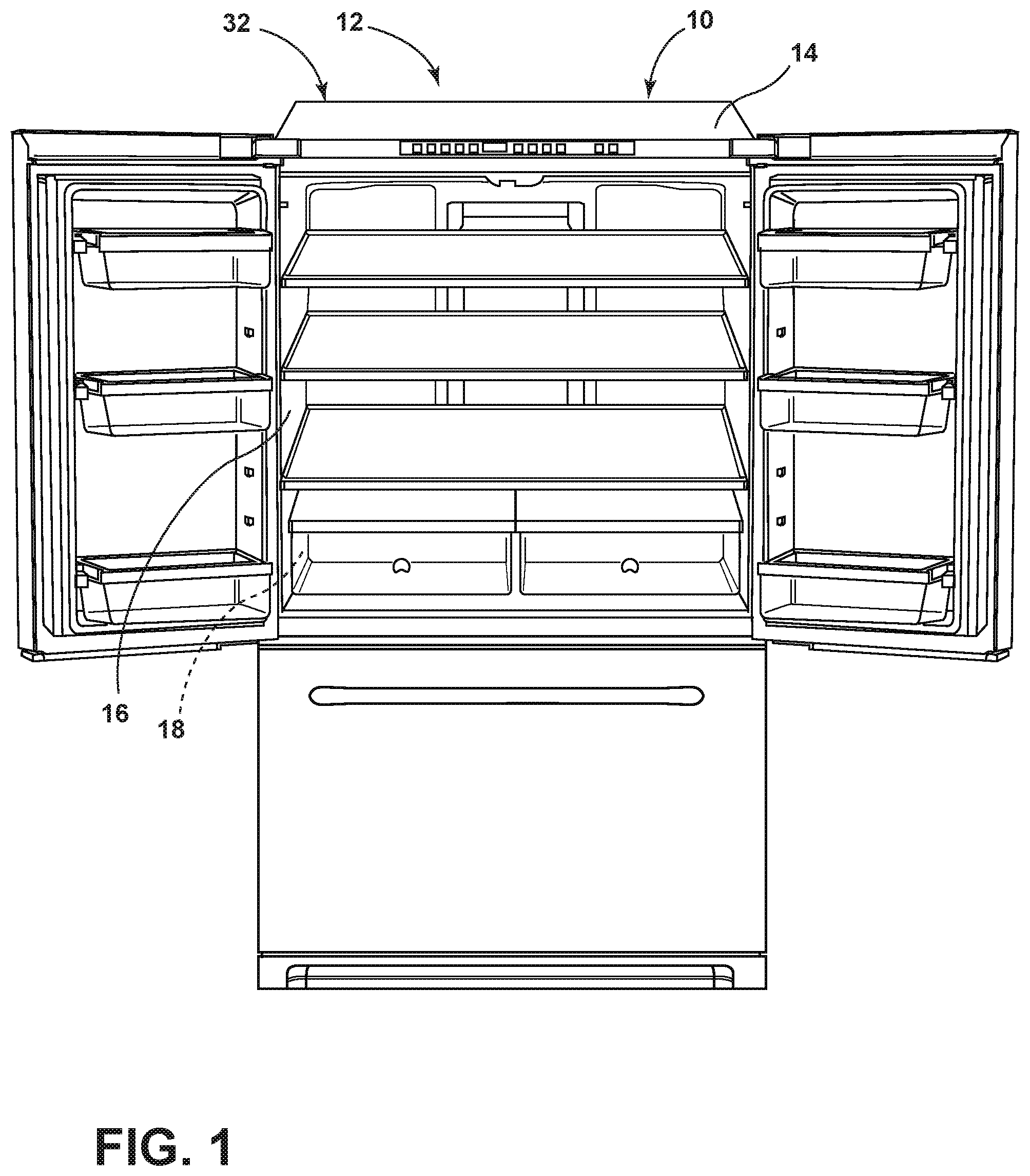
FIG. 1 is a front perspective view of an appliance incorporating an aspect of the vacuum insulated structure formed according to at least one aspect of the method described herein;
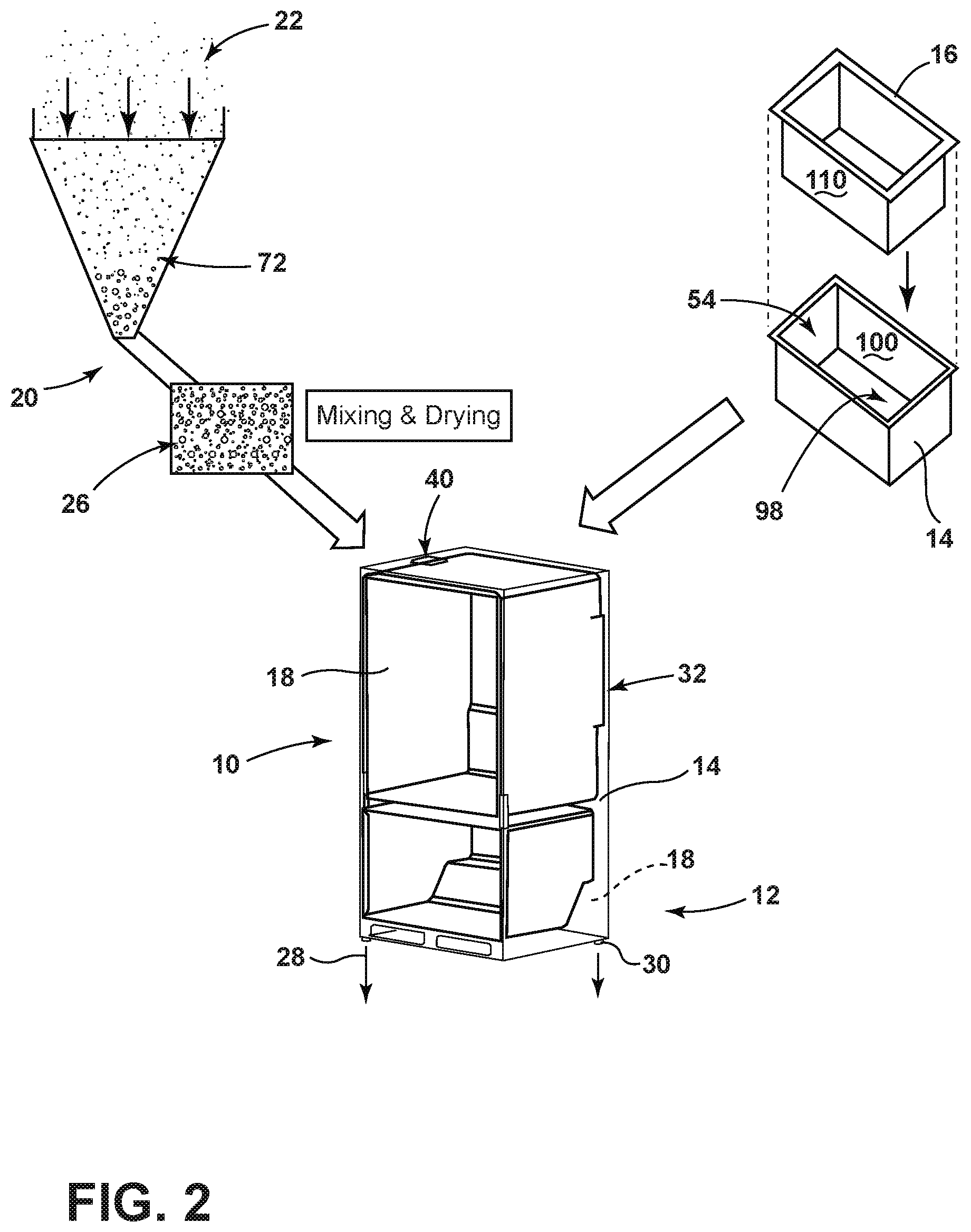
FIG. 2 is a schematic diagram illustrating a first process for forming the vacuum insulated structure;
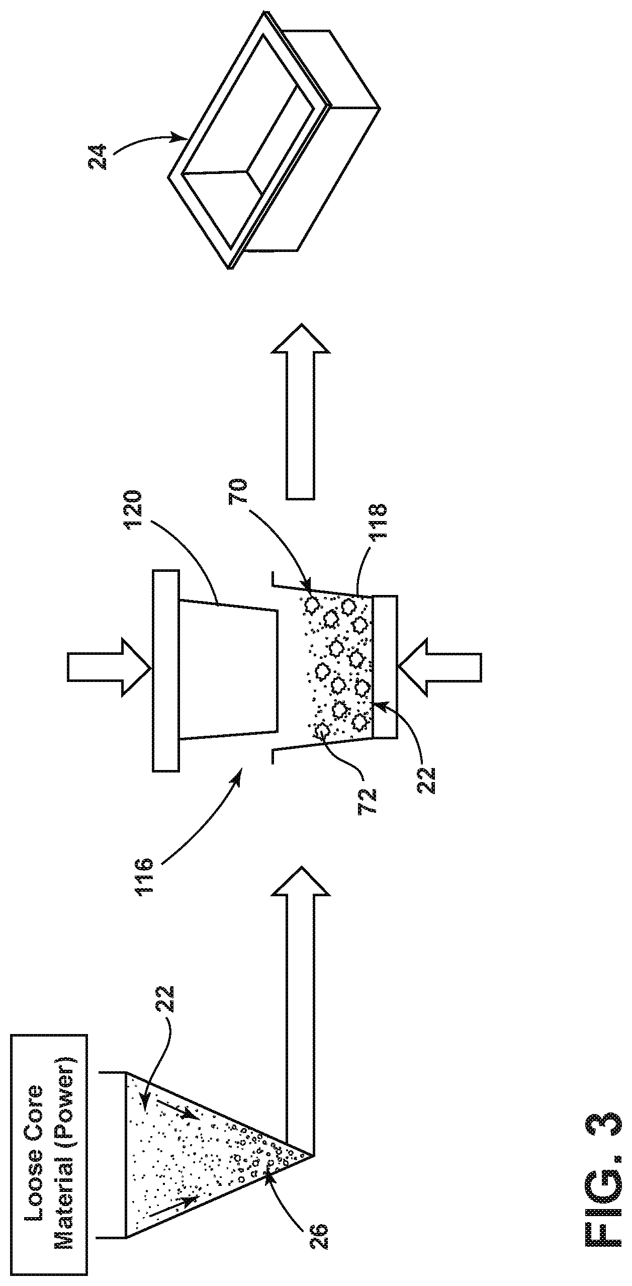
FIG. 3 is a schematic diagram illustrating a method for forming a three-dimensional insulating structure using an aspect of the core insulating powder;
FIG. 4 is a schematic diagram illustrating an aspect of a process for forming a three-dimensional insulated structure using the core powder insulation;
FIG. 5 is a schematic diagram illustrating a process for forming the vacuum insulated structure utilizing a three-dimensional core insulation member;
FIG. 6 is a schematic diagram illustrating an aspect of a method for forming a vacuum insulated structure utilizing a three-dimensional insulating core member;
FIG. 7 is a schematic flow diagram illustrating a method for forming an insulated structure for an appliance;
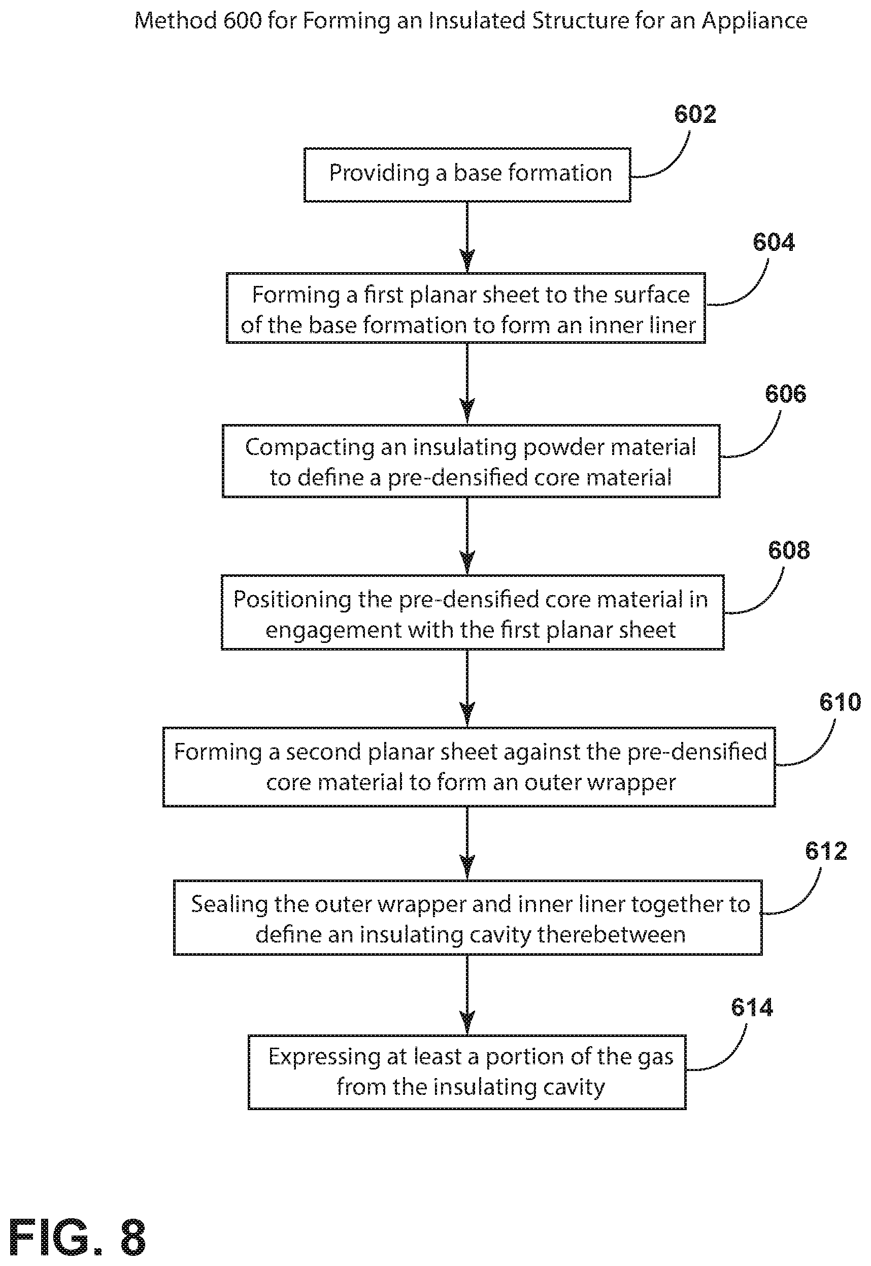
FIG. 8 is a schematic flow diagram illustrating an aspect of a method for forming an insulated structure for an appliance; and
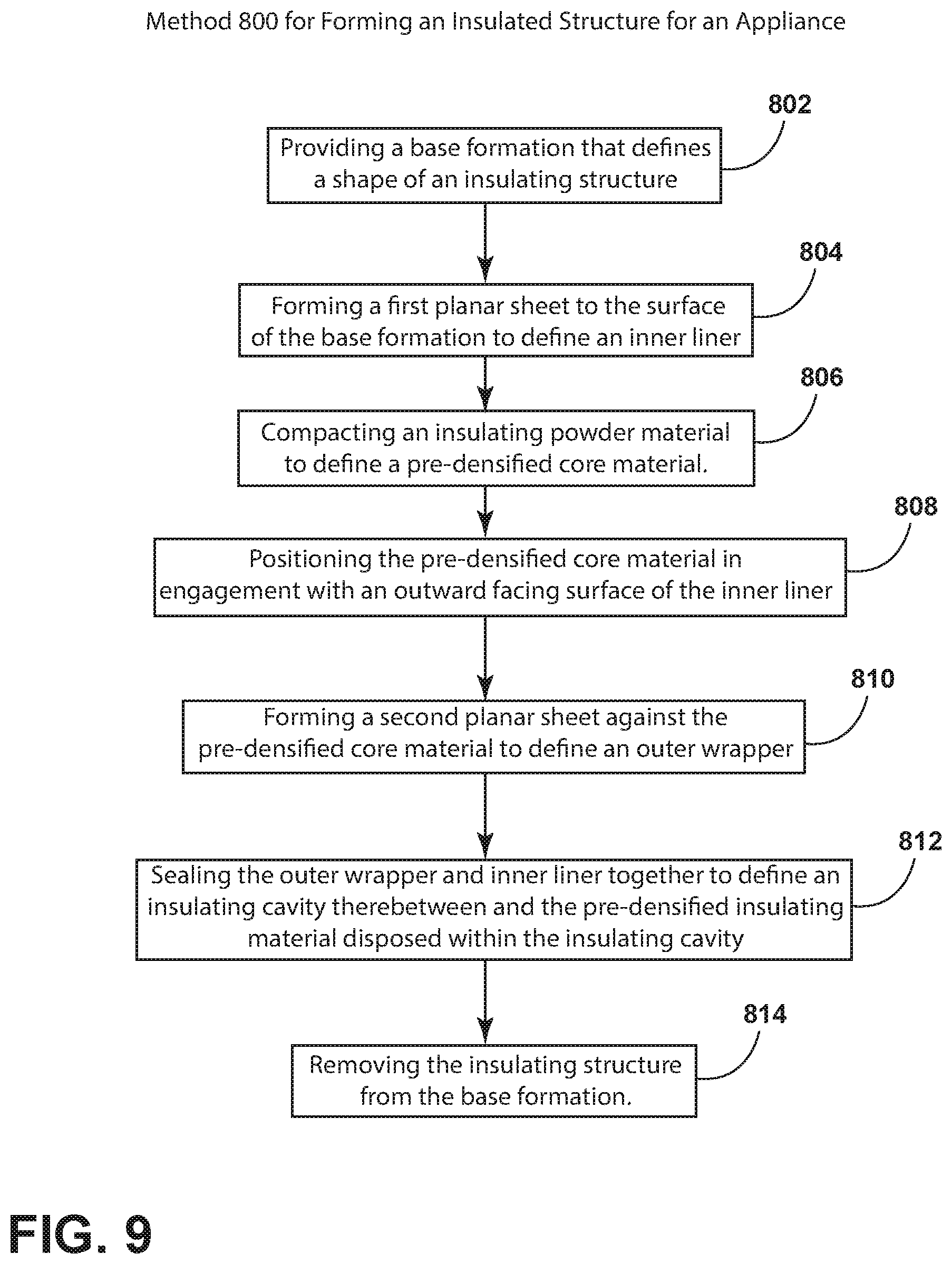
FIG. 9 is a schematic flow diagram illustrating an aspect of a method for forming an insulated structure for an appliance.
DETAILED DESCRIPTION OF EMBODIMENTS
For purposes of description herein the terms "upper," "lower," "right," "left," "rear," "front," "vertical," "horizontal," and derivatives thereof shall relate to the device as oriented in FIG. 1. However, it is to be understood that the device may assume various alternative orientations and step sequences, except where expressly specified to the contrary. It is also to be understood that the specific devices and processes illustrated in the attached drawings, and described in the following specification are simply exemplary embodiments of the inventive concepts defined in the appended claims. Hence, specific dimensions and other physical characteristics relating to the embodiments disclosed herein are not to be considered as limiting, unless the claims expressly state otherwise.
As illustrated in FIGS. 1-6, reference numeral 10 generally refers to an insulating structure that is incorporated within an appliance 12 for providing an insulating functionality to various portions and compartments of the appliance 12. According to the various embodiments, the insulating structure 10 can typically include an outer wrapper 14 and an inner liner 16 that are sealed together and define an insulating cavity 18 between the outer wrapper 14 and the inner liner 16. An insulating material 20 is disposed within the insulating cavity 18, where the insulating material 20 can take any one of various forms. Such forms can be in a powder-type form of a core powder insulation 22, a granulated form of the core powder insulation 22, a pre-densified form of the core powder insulation 22, a densified three-dimensional insulating member 24 made of a core powder insulation 22, combinations thereof, and other similar compacted forms of the core powder insulation 22.
Referring now to FIGS. 2 and 7, a method 400 for forming an insulating structure 10 for an appliance 12 is disclosed. According to the method 400, a structural enclosure, such as an insulating structure 10 that includes the outer wrapper 14 and inner liner 16 is formed (step 402). As discussed above, the insulating cavity 18 can be defined between the outer wrapper 14 and the inner liner 16. The core powder material, which can take the form of an insulating powder material 20, is formed (step 404). It is contemplated that the insulating powder material 20 can be made of various nano/micro-sized particulate material that can include, but is not limited to, powdered silica (fume or precipitated), granulated silica, other silica material, powder aerogel, hollow glass spheres, pearlite, rice husk ash, fly ash, silica fume, diatomaceous earth, carbon black and silicon carbide, combinations thereof, and other nano-sized and/or micro-sized particulate material. According to various embodiments, the insulating powder material 20 is compacted to form a pre-densified core material 26 (step 406). It is contemplated that the pre-densified core material 26 can take the form of a granulated aspect of the insulating powder material 20. The pre-densified core material 26 can then be further prepared for deposition into an insulating structure 10. Such further preparation can include mixing the pre-densified core material 26 with other additives and insulating materials 20 and also drying the pre-densified core material 26 to insure that substantially all of the fluid is evaporated or otherwise removed from the pre-densified core material 26. Such additives can include, but are not limited to, hollow glass spheres, glass fibers, pearlite, rice husk ash, fly ash, silica fume, diatomaceous earth, carbon black and silicon carbide, combinations thereof and other similar insulating additives.
Referring again to FIGS. 2 and 7, once the pre-densified core material 26 is prepared, the pre-densified core material 26 is disposed within the insulating cavity 18 of the insulating structure 10 (step 408). Once disposed therein, the insulating structure 10 can be hermetically sealed and at least a portion of the gas 28 contained within the insulating cavity 18 can be expressed through at least one vacuum port 30 (step 410). In this manner, the hermetically sealed insulating structure 10 forms a vacuum insulated structure 32.
Referring now to FIGS. 2-6, it is contemplated that the pre-densified core material 26 can be positioned within the insulating cavity 18 and between the inner liner 16 and outer wrapper 14 before the outer wrapper 14 and inner liner 16 are attached and/or sealed together. In such an embodiment, it is contemplated that the pre-densified core material 26 can be disposed within the outer wrapper 14 and the inner liner 16 can be placed thereon. The final compaction of the pre-densified core material 26 in this embodiment can occur as the inner liner 16 is placed within the outer wrapper 14, and the pre-densified core material 26 is compressed to substantially conform to the shape of the insulating cavity 18 defined between the outer wrapper 14 and the inner liner 16.
According to various alternate embodiments, it is contemplated that the pre-densified core material 26 can be disposed within the insulating cavity 18 through an inlet port 40 defined in one of the outer wrapper 14 and inner liner 16. In such an embodiment, it is contemplated that the pre-densified core material 26 is disposed within the insulating cavity 18 after the outer wrapper 14 and inner liner 16 are attached and, in certain embodiments, sealed together. It is also contemplated that a compaction of the pre-densified core material 26 into the finally compacted three-dimensional insulating member 24 of the vacuum insulating structure 10 can occur during expression of gas 28 from the insulated cavity. In such an embodiment, the expression of gas 28 from the insulating cavity 18 can result in a negative compressive force being exerted upon the pre-densified core material 26 to further compress the pre-densified core material 26 into a finally compacted three-dimensional insulating member 24 disposed within the insulating cavity 18. Where the pre-densified core material 26 is disposed in the insulating cavity 18 via the inlet port 40, the compaction of the pre-densified core material 26 can be assisted through various vibrating and/or rotating mechanisms that serve to position the particles of the pre-densified core material 26 in a more densified state and throughout the insulating cavity 18. The vibrating and rotating mechanisms adjust the positioning of the pre-densified core material 26 such that the insulating structure 12 is shaken and rotated to manipulate the pre-densified core material 26 to occupy the entire insulating cavity 18.
Referring now to FIGS. 3-6, according to various embodiments, it is contemplated that the step of forming the structural enclosure can include wrapping a planar sheet 50 around a base formation 52. In such an embodiment, the wrapped planar sheet 50 can take the form of the inner liner 16 such that the base formation 52 defines at least one compartment of the appliance 12 defined by the inward facing surface 56 of the inner liner 16. It is also contemplated that a base formation 52 can include a forming cavity 58 within which the planar sheet 50 is disposed. In these embodiments, the planar sheet 50 is formed within the forming cavity 58 to form the outer wrapper 14. It is contemplated that where the base formation 52 is used, the insulating structure 10 can remain upon the base formation 52 at least until the pre-densified core material 26 is disposed within the insulating cavity 18 of the insulating structure 10 and the inner liner 16 and outer wrapper 14 are sealed together.
Referring again to FIGS. 3 and 4, it is contemplated that the pre-densified core material 26 can take the form of a three-dimensional insulating member 24 that can be disposed as a single piece between the inner liner 16 and outer wrapper 14 of the insulating structure 10. It is contemplated that in order to keep the three-dimensional shape of the three-dimensional insulating member 24, the three-dimensional insulating member 24 can include at least one binder material 70. Such binder materials 70 can include, but are not limited to, various cellulose compounds, wax, polyethylene glycol, gelatin, starch, polyvinyl alcohol, polymethacrylates, sodium silicates, combinations thereof, and other similar organic and inorganic materials that can be included within the pre-densified core material 26 to form and maintain the shape of the three-dimensional insulating member 24. It is contemplated that the three-dimensional insulating member 24 can be formed through a compaction of the pre-densified core material 26, or through compaction of the insulating powder material 20. It is further contemplated that the three-dimensional insulating member 24 can be made by compacting both the pre-densified core material 26 and also the insulating powder material 20 that have been mixed together to form a substantially uniform insulating material 20. It is contemplated that the use of both a pre-densified granular insulating material 72 and the insulating powder material 20 to be compacted to form the three-dimensional insulating member 24 can serve to allow the particles of the insulating powder material 20 to fit between the porous spaces defined between the larger particles of the granular insulating material 72. In this manner, compaction of the insulating mixture made up of the insulating powder material 20 and the pre-densified granular insulating material 72 can be a densified three-dimensional insulating member 24 having a substantially consistent and uniform distribution of particles of the insulating powder material 20 and the granular insulating material 72.
Referring again to FIGS. 3, 4 and 6, it is contemplated that after the three-dimensional insulating member 24 or core member is formed, the three-dimensional insulating member 24 can be bonded to one or both of the outer wrapper 14 and the inner liner 16. This bonding step can serve to minimize the amount of air spaces that may exist between the three-dimensional core member and the outer wrapper 14 and the inner liner 16. The bonding step can be performed by welding, adhesives, bonding agents, combinations thereof and other similar methods and materials.
Referring again to FIGS. 1-6 and 8, a method 600 is disclosed for forming an insulated structure for an appliance 12. According to various aspects of the method 600, a base formation 52 is provided where a surface 80 of the base formation 52 defines a shape of the insulating structure 10 or insulating enclosure (step 602). As discussed above, the base formation 52 can be in the form of a positive volume around which a planar sheet 50 is formed to define the inner liner 16. As also discussed above, the base formation 52 can take the form of a forming cavity 58 within which a planar sheet 50 can be formed to define the outer wrapper 14. According to the method 600, a first planar sheet 90 can be formed to the surface 80 of the base formation 52 (step 604). It is contemplated that the first planar sheet 90 can be formed to define either the outer wrapper 14 or the inner liner 16 of the insulating structure 10. As discussed above, the insulating powder material 20 can be compacted to define a pre-densified core material 26 (step 606). The pre-densified core material 26 can take the form of a granular insulating material 72 where various portions of the insulating powder material 20 are compacted into larger granular sized pieces of insulating material 20. The sizes of the particles of the pre-densified core material 26 and the granular sizes of the insulating material 20 can vary. By way of example, and not limitation, such particle and/or granule sizes can range from approximately 250 microns to approximately 5000 microns. It is contemplated that smaller particle sizes and larger granule sizes can be implemented. In order to maintain the size and shape of the granular insulating material 72, the particles of the granular insulating material 72 can be combined with the binder material 70 that provides each granule of the granular insulating material 72 with greater compressive strength than various granules without the binder material 70. It is also contemplated that the pre-densified core material 26 can take the form of a three-dimensional insulating member 24, where the three-dimensional insulating member 24 can include one or more of the binder materials 70 to maintain the shape of the three-dimensional insulating member 24. In this manner, the binder materials 70 allow the three-dimensional insulating member 24 to be handled more easily without substantially disintegrating, degrading, or otherwise becoming damaged. It is further contemplated that the three-dimensional insulating member 24 can be wrapped in a high barrier metallized film 74 having one or more layers or other membrane to allow the three-dimensional insulating member 24 to be handled without substantial damage.
Referring again to FIGS. 3-6 and 8, the pre-densified core material 26 can be positioned in engagement with the formed first planar sheet 90 (step 608). As discussed above, where the pre-densified core material 26 is a granular insulating material 72, the granular insulating material 72 can be poured into the outer wrapper 14 and the inner liner 16 placed on top. The inner liner 16 and outer wrapper 14 can be pressed together such that the granular insulating material 72 is compacted further to form the three-dimensional insulating member 24 by pressing the inner liner 16 into the outer wrapper 14, thereby compressing the pre-densified core material 26. Alternatively, where the pre-densified core material 26 is a three-dimensional insulating member 24, it is contemplated that the three-dimensional insulating member 24 can be either placed over the inner liner 16, or placed within the outer wrapper 14. Once the pre-densified core material 26 is placed within engagement of the first planar sheet 90, a second planar sheet 92 is formed substantially to the shape of the three-dimensional insulating member 24 and placed against the pre-densified core material 26. It is contemplated that the second planar sheet 92 can include the other of the outer wrapper 14 and inner liner 16 that engages the first planar sheet 90 formed on the surface 80 of the base formation 52 (step 610). The outer wrapper 14 and inner liner 16 can then be sealed together to define an insulating cavity 18 between the outer wrapper 14 and the inner liner 16 (step 612). It is contemplated that the pre-densified core material 26 is disposed within the insulating cavity 18 between the inner liner 16 and the outer wrapper 14. At least a portion of the gas 28 contained within the insulating cavity 18 can be expressed from the insulating cavity 18 (step 614). It is contemplated that the insulating cavity 18 can then be hermetically sealed to define the vacuum insulated structure 32 with the compacted and pre-densified core material 26 disposed therein.
Referring again to FIGS. 3-6, where the first planar sheet 90 defines the outer wrapper 14, the pre-densified core material 26 can be disposed within a wrapper volume 98 defined by an interior surface 100 of the outer wrapper 14. As discussed above, in such an embodiment, the pre-densified core material 26 can take the form of the granular insulating material 72 for the three-dimensional insulating member 24. Once disposed within the wrapper volume 98, the inner liner 16 can be placed over the outer wrapper 14 such that the granular insulating material 72 can be compacted, or such that the three-dimensional insulating member 24 can be disposed in the insulating cavity 18 between the inner liner 16 and the outer wrapper 14.
Referring again to FIGS. 5 and 6, where the first planar sheet 90 is the inner liner 16, the pre-densified core material 26, typically in the form of a three-dimensional insulating member 24, is disposed against an outward facing surface 110 of the inner liner 16. In this manner, the three-dimensional insulating member 24 surrounds the outward facing surface 110 of the inner liner 16 such that the outer wrapper 14 can be placed over the three-dimensional insulating member 24 and sealed with the inner liner 16 to form the insulating cavity 18 and, in turn, the insulating structure 10. It is contemplated that in such an embodiment, the three-dimensional core member can be bonded to at least the outward facing surface 110 of the inner liner 16. The three-dimensional insulating member 24 can also be bonded to the outer wrapper 14 proximate the insulating cavity 18.
According to the various embodiments of the methods described herein, the insulating powder material 20 is disposed into direct engagement with the inner liner 16 and the outer wrapper 14. This is the case whether the insulating powder material 20 is in powder form, granular form, or in the form of the three-dimensional insulating member 24. In this manner, the vacuum insulated structure 32 can be formed without the use of barrier films or porous bags that may separate the insulating material 20 from the inner liner 16 and/or the outer wrapper 14.
Referring again to FIGS. 2-6 and 9, a method 800 is disclosed for forming an insulated structure for an appliance 12. According to the method 800, a base formation 52 is provided, where a surface 80 of the base formation 52 defines a shape of an insulating structure 10 or insulating enclosure (step 802). According to the method 800, a first planar sheet 90 is formed at the surface 80 of the base formation 52, where the first planar sheet 90 defines the inner liner 16 of the insulating structure 10 (step 804). The insulating powder is then compacted to define the pre-densified core material 26 (step 806). As discussed above, the pre-densified core material 26 can be compacted in the form of a three-dimensional insulating member 24 or in the form of a granular insulating material 72. The three-dimensional insulating member 24 can be in the form of a contoured shape that conforms to the shape of a portion of the inner liner 16 and/or the outer wrapper 14. The three-dimensional insulating member 24 can also be in the form of an insulating panel that is generally rectilinear and/or cuboidal in configuration. According to the method 800, the pre-densified core material 26 is then positioned in engagement with an outward facing surface 110 of the inner liner 16 (step 808). In such an embodiment, the pre-densified core material 26 will, typically, take the form of a three-dimensional insulating member 24. In this manner, the three-dimensional insulating member 24 can be placed over the outward facing surface 110 of the inner liner 16 and the three-dimensional insulating member 24 can maintain its shape, or substantially maintain its shape, during formation of the insulating structure 10. A second planar sheet 92 is then formed to define the outer wrapper 14.
According to various embodiments, the outer wrapper 14 can be formed against a separate base formation 52, or can be formed around a portion of the pre-densified core material 26 (step 810). It is contemplated that the inner liner 16 and outer wrapper 14 can take the form of a metal panel that is shaped, pressed, punched, or otherwise manipulated to take the form of the inner liner 16 and/or the outer wrapper 14. It is further contemplated that the inner liner 16 and outer wrapper 14 can be made of a polymer-type material. In such an embodiment, the polymer-type material can be blow molded, vacuum formed, thermoformed, injection-molded, compression molded, or otherwise shaped to form the inner liner 16 and/or the outer wrapper 14. Where a plastic-type material is used, the outer wrapper 14 and the inner liner 16 can include various barrier layers or films that can vary depending on the design of the insulating structure 10 and the insulating requirements thereof.
According to the method 800, as exemplified in FIGS. 2-6 and 9, after the outer wrapper 14 is placed over the pre-densified core material 26 and the inner liner 16, the outer wrapper 14 and inner liner 16 are sealed together to define the insulating cavity 18 (step 812). In this manner, the pre-densified core material 26 is contained within the insulating cavity 18 to define the insulating structure 10 for the appliance 12. After the insulating structure 10 is formed, it is contemplated that the insulating structure 10 can be removed from the base formation 52 (step 814). It is also contemplated that the insulating structure 10 can be removed from the base formation 52 after gas 28 is expressed from the insulating cavity 18 and the vacuum insulated structure 32 is formed. As such, the expressing step can be performed while the insulating structure 10 is engaged with the base formation 52 and removed after the vacuum insulating structure 10 is formed.
According to the various embodiments, aspects of the step 806 of compacting the insulating powder material 20 and/or the granular insulating material 72 into the three-dimensional insulating member 24 or 2D VIP or 2D core panels can be performed either between the inner liner 16 and outer wrapper 14, or can be performed in a separate pressing assembly 116 where the insulating material 20 is disposed within a compression cavity 118 and a compression member 120 is disposed within the compression cavity 118 to compress the insulating material 20 into the three-dimensional insulating member 24. It is contemplated that the binder material 70 can be disposed within the compression cavity 118 and mixed in with the insulating material 20 such that when the three-dimensional insulating member 24 is formed, the binder material 70 substantially retains the three-dimensional insulating member 24 in its shape for removal from the compression cavity 118 and placement on either the inner liner 16 or within the outer wrapper 14 to form the insulating structure 10.
It is contemplated that the various aspects of the devices and methods described herein can be utilized to form various insulating forms that include, but are not limited to, three-dimensional insulating members 24, insulating panels, planar core members, plural and contoured three-dimensional vacuum insulated panels, and others. It is also contemplated that the insulating member or members formed using the aspects of the device can be used within various appliances 10. Such appliances 10 can include, but are not limited to, refrigerators, freezers, warmers, ovens, dishwashers, laundry appliances, water heaters, furnaces, and other similar appliances.
It will be understood by one having ordinary skill in the art that construction of the described device and other components is not limited to any specific material. Other exemplary embodiments of the device disclosed herein may be formed from a wide variety of materials, unless described otherwise herein.
For purposes of this disclosure, the term "coupled" (in all of its forms, couple, coupling, coupled, etc.) generally means the joining of two components (electrical or mechanical) directly or indirectly to one another. Such joining may be stationary in nature or movable in nature. Such joining may be achieved with the two components (electrical or mechanical) and any additional intermediate members being integrally formed as a single unitary body with one another or with the two components. Such joining may be permanent in nature or may be removable or releasable in nature unless otherwise stated.
It is also important to note that the construction and arrangement of the elements of the device as shown in the exemplary embodiments is illustrative only. Although only a few embodiments of the present innovations have been described in detail in this disclosure, those skilled in the art who review this disclosure will readily appreciate that many modifications are possible (e.g., variations in sizes, dimensions, structures, shapes and proportions of the various elements, values of parameters, mounting arrangements, use of materials, colors, orientations, etc.) without materially departing from the novel teachings and advantages of the subject matter recited. For example, elements shown as integrally formed may be constructed of multiple parts or elements shown as multiple parts may be integrally formed, the operation of the interfaces may be reversed or otherwise varied, the length or width of the structures and/or members or connector or other elements of the system may be varied, the nature or number of adjustment positions provided between the elements may be varied. It should be noted that the elements and/or assemblies of the system may be constructed from any of a wide variety of materials that provide sufficient strength or durability, in any of a wide variety of colors, textures, and combinations. Accordingly, all such modifications are intended to be included within the scope of the present innovations. Other substitutions, modifications, changes, and omissions may be made in the design, operating conditions, and arrangement of the desired and other exemplary embodiments without departing from the spirit of the present innovations.
It will be understood that any described processes or steps within described processes may be combined with other disclosed processes or steps to form structures within the scope of the present device. The exemplary structures and processes disclosed herein are for illustrative purposes and are not to be construed as limiting.
It is also to be understood that variations and modifications can be made on the aforementioned structures and methods without departing from the concepts of the present device, and further it is to be understood that such concepts are intended to be covered by the following claims unless these claims by their language expressly state otherwise.
The above description is considered that of the illustrated embodiments only. Modifications of the device will occur to those skilled in the art and to those who make or use the device. Therefore, it is understood that the embodiments shown in the drawings and described above is merely for illustrative purposes and not intended to limit the scope of the device, which is defined by the following claims as interpreted according to the principles of patent law, including the Doctrine of Equivalents.
* * * * *
D00000
D00001
D00002
D00003
D00004
D00005
D00006
D00007
D00008
D00009
XML
uspto.report is an independent third-party trademark research tool that is not affiliated, endorsed, or sponsored by the United States Patent and Trademark Office (USPTO) or any other governmental organization. The information provided by uspto.report is based on publicly available data at the time of writing and is intended for informational purposes only.
While we strive to provide accurate and up-to-date information, we do not guarantee the accuracy, completeness, reliability, or suitability of the information displayed on this site. The use of this site is at your own risk. Any reliance you place on such information is therefore strictly at your own risk.
All official trademark data, including owner information, should be verified by visiting the official USPTO website at www.uspto.gov. This site is not intended to replace professional legal advice and should not be used as a substitute for consulting with a legal professional who is knowledgeable about trademark law.