Device for maintaining internal temperature of pressure vessel
Jang , et al. February 2, 2
U.S. patent number 10,907,770 [Application Number 16/439,017] was granted by the patent office on 2021-02-02 for device for maintaining internal temperature of pressure vessel. This patent grant is currently assigned to Kepco Nuclear Fuel Co., Ltd.. The grantee listed for this patent is Min Young Choi, Hun Jang, Yoon Ho Kim, Dae Gyun Ko, Sung Yong Lee, Yong Kyoon Mok, Jong Sung Yoo. Invention is credited to Min Young Choi, Hun Jang, Yoon Ho Kim, Dae Gyun Ko, Sung Yong Lee, Yong Kyoon Mok, Jong Sung Yoo.
| United States Patent | 10,907,770 |
| Jang , et al. | February 2, 2021 |
Device for maintaining internal temperature of pressure vessel
Abstract
A device for maintaining the internal temperature of a pressure vessel. The device includes a pressure vessel equipped with a main heater for heating test water to a predetermined test temperature and for maintaining the predetermined test temperature, a preheater for primarily heating the test water to the predetermined test temperature before the main heater heats the test water, and a heat exchanger including an feed pipe for feeding the test water heated by the preheater to the pressure vessel and a discharge pipe for transporting the test water discharged from the pressure vessel, in which the feed pipe is disposed inside the discharge pipe.
| Inventors: | Jang; Hun (Sejong, KR), Mok; Yong Kyoon (Daejeon, KR), Kim; Yoon Ho (Daejeon, KR), Choi; Min Young (Daejeon, KR), Ko; Dae Gyun (Daejeon, KR), Lee; Sung Yong (Daejeon, KR), Yoo; Jong Sung (Daejeon, KR) | ||||||||||
|---|---|---|---|---|---|---|---|---|---|---|---|
| Applicant: |
|
||||||||||
| Assignee: | Kepco Nuclear Fuel Co., Ltd.
(Daejeon, KR) |
||||||||||
| Family ID: | 1000005335586 | ||||||||||
| Appl. No.: | 16/439,017 | ||||||||||
| Filed: | June 12, 2019 |
Prior Publication Data
| Document Identifier | Publication Date | |
|---|---|---|
| US 20190293237 A1 | Sep 26, 2019 | |
Related U.S. Patent Documents
| Application Number | Filing Date | Patent Number | Issue Date | ||
|---|---|---|---|---|---|
| PCT/KR2017/005474 | May 25, 2017 | ||||
Foreign Application Priority Data
| Dec 12, 2016 [KR] | 10-2016-0168613 | |||
| Current U.S. Class: | 1/1 |
| Current CPC Class: | G21C 17/06 (20130101); G01N 17/02 (20130101); F17C 1/12 (20130101) |
| Current International Class: | F17C 1/12 (20060101); G01N 17/02 (20060101); G21C 17/06 (20060101) |
References Cited [Referenced By]
U.S. Patent Documents
| 2948516 | August 1960 | Martinelli |
| 3141324 | July 1964 | Boies |
| 3147191 | September 1964 | Crowther |
| 3660231 | May 1972 | Fox |
| 3663725 | May 1972 | Pearl |
| 3670561 | June 1972 | Hundere |
| 3960496 | June 1976 | Schieber |
| 4176544 | December 1979 | Eyles |
| 4283200 | August 1981 | Bodmer |
| 4339945 | July 1982 | Knudsen |
| 4426880 | January 1984 | Walters |
| 4628870 | December 1986 | Draper |
| 4635589 | January 1987 | Draper |
| 4640233 | February 1987 | Draper |
| 4654187 | March 1987 | Fejes |
| 4660510 | April 1987 | Draper |
| 4727826 | March 1988 | Draper |
| 4833622 | May 1989 | Barto |
| RE33346 | September 1990 | Knudsen |
| 4978506 | December 1990 | Calderwood |
| 5101658 | April 1992 | Wilson, III |
| 5178822 | January 1993 | Buford, III |
| 5268103 | December 1993 | Jameson |
| 5334291 | August 1994 | Gavlin |
| 5428653 | June 1995 | El-Genk |
| 5430779 | July 1995 | Baversten |
| 5531103 | July 1996 | Eaton |
| 5596613 | January 1997 | Gluntz |
| 6159427 | December 2000 | Kherani |
| 6381962 | May 2002 | Ohshita |
| 9182114 | November 2015 | Price |
| 9765978 | September 2017 | Billings |
| 2010/0281954 | November 2010 | Oh |
| 2012/0192813 | August 2012 | Evans |
| 2013/0044851 | February 2013 | Winters |
| 2019/0352194 | November 2019 | Thiers |
| 2009-156679 | Jul 2009 | JP | |||
| 4619398 | Jan 2011 | JP | |||
| 2014-163780 | Sep 2014 | JP | |||
| 10-1103978 | Jan 2012 | KR | |||
| 10-1143220 | May 2012 | KR | |||
Attorney, Agent or Firm: Reinhart Boerner Van Deuren P.C.
Parent Case Text
CROSS-REFERENCE TO RELATED PATENT APPLICATIONS
This patent application is a continuation of PCT/KR2017/005474, filed May 25, 2017, which claims priority to Korean Patent Application No. 10-2016-0168613, filed Dec. 12, 2016, the entire teachings and disclosure of which are incorporated herein by reference thereto.
Claims
The invention claimed is:
1. A device for maintaining an internal temperature of a pressure vessel, the device comprising: the pressure vessel equipped with a main heater for heating test water to a predetermined test temperature and for maintaining the predetermined test temperature; a preheater for primarily heating the test water to the predetermined test temperature before the main heater heats the test water; and a heat exchanger including a feed pipe for feeding the test water heated by the preheater to the pressure vessel and a discharge pipe for transporting the test water discharged from the pressure vessel, wherein the feed pipe is disposed inside the discharge pipe.
2. The device according to claim 1, wherein the feed pipe is inserted into the pressure vessel from the bottom side and extends up to an upper portion of the pressure vessel.
3. The device according to claim 1, wherein the pressure vessel further includes a specimen holding rack for holding a plurality of specimens.
4. The device according to claim 3, wherein the specimen holding rack has a plurality of hooks.
Description
TECHNICAL FIELD
The present invention relates to a temperature maintaining device for a pressure vessel. More particularly, the present invention relates to a device for maintaining the internal temperature of a pressure vessel by controlling the temperature of test water that passes through the pressure vessel.
BACKGROUND
Typically, nuclear power plants produce electricity using fission energy generated from a nuclear fuel in a reactor. Most nuclear power plants in Korea use a pressurized water reactor (PWR). This nuclear reactor, PWR, transfers fission energy (i.e., the energy released by the fission of atoms) to a turbine by using light water. Most of the parts constituting a reactor are exposed to high-pressure hot water. Therefore, deterioration of the integrity of equipment frequently occurs due to various degradation mechanisms such as corrosion, stress corrosion cracking, and corrosion fatigue. In particular, reduction in thickness of nuclear fuel claddings in a high-pressure hot water environment inside a nuclear reactor is one of the most important factors affecting the design of a reactor.
The current operating conditions of nuclear power plants require a nuclear fuel for high burnup which can extend a fuel cycle to reduce the cycle cost of a nuclear fuel as a part of improving the economic feasibility. Therefore, much effort is being made to improve the corrosion damage resistance of the nuclear fuel cladding. In order to increase the corrosion resistance of zirconium alloys used as the material of nuclear fuel cladding, various efforts such as development of new alloys and control of water chemistry factors have been made.
The corrosion characteristics of zirconium alloys used as the material of the nuclear fuel cladding needs to be evaluated in a situation simulating the environment of the primary side of a nuclear power plant, which is the environment in which the nuclear fuel cladding is exposed to water. In order to simulate the environment of the primary side of a nuclear power plant, an environmental simulator composed of various complicated devices such as devices for maintaining a high-pressure hot water environment and devices for controlling water chemistry factors is needed. For example, a pressure vessel is required to test for corrosion of zirconium alloys in a high-pressure hot water environment. These devices are complicated in structure. Thus, high costs for manufacturing, operation, and maintenance of expensive test equipment are incurred. In addition, the corrosion test of zirconium alloys takes a very long test time. Therefore, to improve test efficiency, it is desirable to put as many specimens as possible into a single pressure vessel. This reduces the number of pieces of test equipment and shortens a total test time, thereby improving test efficiency.
As to a pressure vessel to accommodate specimens for corrosion test of a zirconium alloy that is a typical cladding material, it is increasingly difficult to maintain the interior of the pressure vessel at a constant temperature as the size of the pressure vessel is increased. In most cases, the upper part of a pressure vessel is maintained at a relatively high temperature and the lower part is maintained at a relatively low temperature. As the size of a pressure vessel increases, the temperature difference between the upper and lower parts becomes larger. To increase test efficiency by loading as many specimens as possible in a pressure vessel, it is necessary to attach specimens to the entire area of the pressure vessel. However, in that case, accurate experimental data cannot be obtained due to the temperature difference inside the pressure vessel.
Therefore, a current approach to obtain accurate experimental data from a corrosion test is to increase the number of pressure vessels used for a corrosion test. However, this method has disadvantages: high equipment costs for manufacturing or purchasing pressure vessels; and high accessory costs for purchasing high-pressure pumps and heaters required to create a similar environment to the actual operation environment of a reactor.
Document of Related Art
Korean Patent No. 10-1143220 (published as of May 18, 2012)
The present invention has been made in view of the above problems, and it is an object of the present invention to provide a device for maintaining the internal temperature of a pressure vessel at a constant level so that a plurality of specimens can be mounted in the pressure vessel.
BRIEF SUMMARY
To achieve the object of the invention, according to one aspect of the present invention, there is provided a device for maintaining the internal pressure of a pressure vessel at a constant level, the device including: the pressure vessel equipped with a main heater for heating test water to a predetermined test temperature and maintaining the predetermined test temperature; a preheater for primarily heating the test water to the predetermined test temperature before the main heater heats the test water; and a heat exchanger including a feed pipe for feeding the test water heated by the preheater to the pressure vessel and a discharge pipe for transporting the test water discharged from the pressure vessel, wherein the feed pipe is disposed inside the discharge pipe.
Preferably, the feed pipe may be inserted into the pressure vessel from the bottom side and extend up to an upper portion of the pressure vessel.
Preferably, the pressure vessel may include a specimen holding rack for holding a plurality of specimens.
Preferably, the specimen holding rack has a plurality of hooks.
The device for holding the internal temperature of a pressure vessel at a constant level, according to the present invention, can maintain the temperature of the test water contained in the pressure vessel. Therefore, even when many specimens are loaded into a pressure vessel, accurate experimental data can be obtained, a test time can be shortened, and the test costs can be reduced.
BRIEF DESCRIPTION OF DRAWINGS
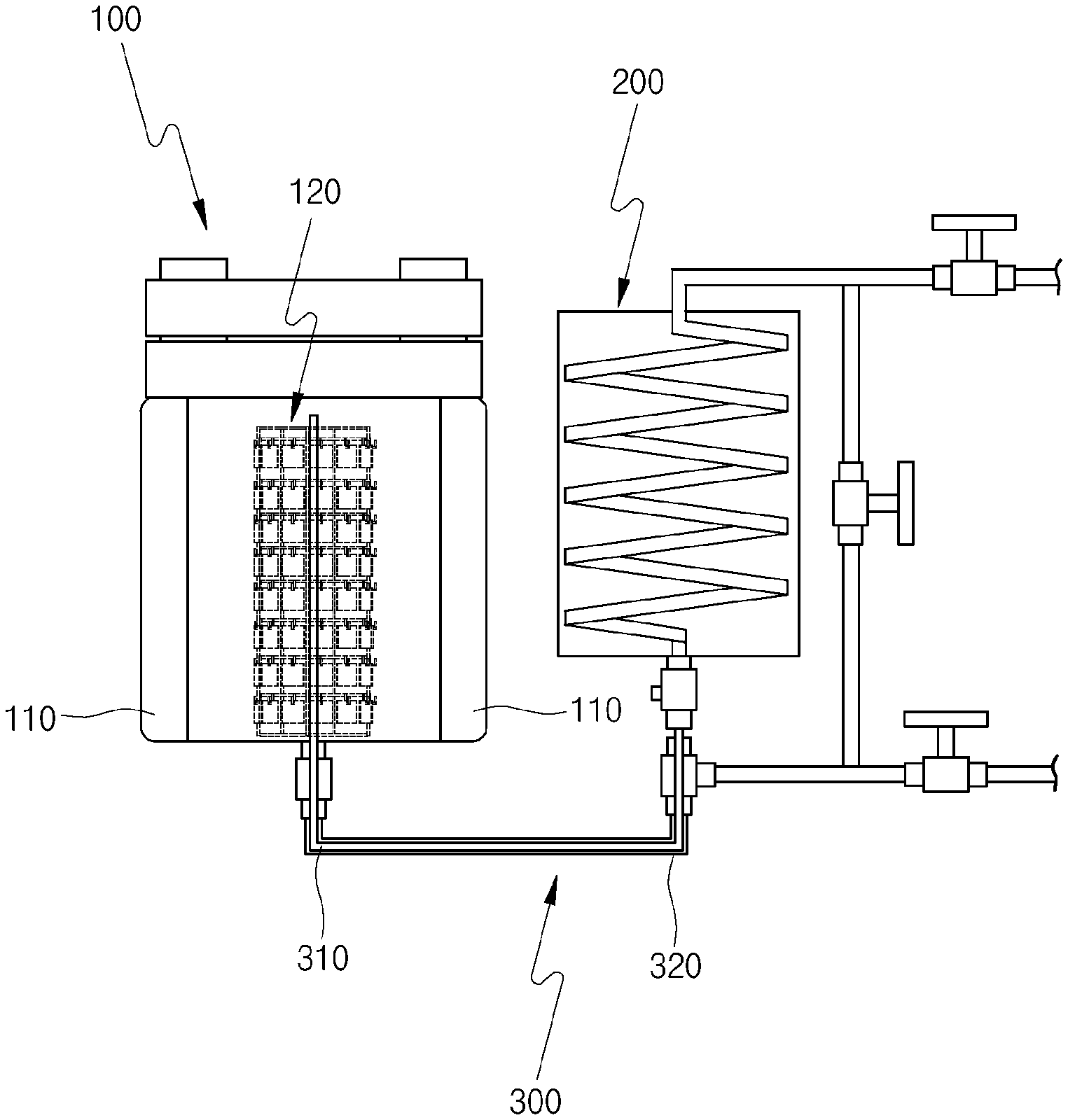
FIG. 1 is a cross-sectional view illustrating a device for maintaining the internal temperature of a pressure vessel at a constant level, according to one embodiment of the present invention;
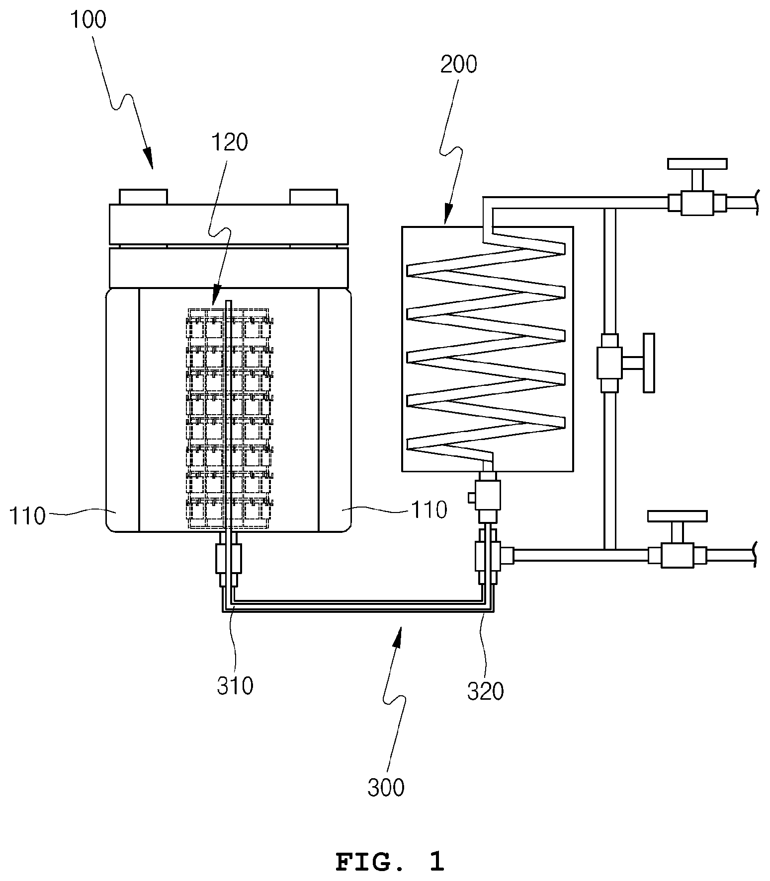
FIG. 2 is an enlarged view illustrating a heat exchanger of the temperature maintaining device according to the embodiment of the present invention;
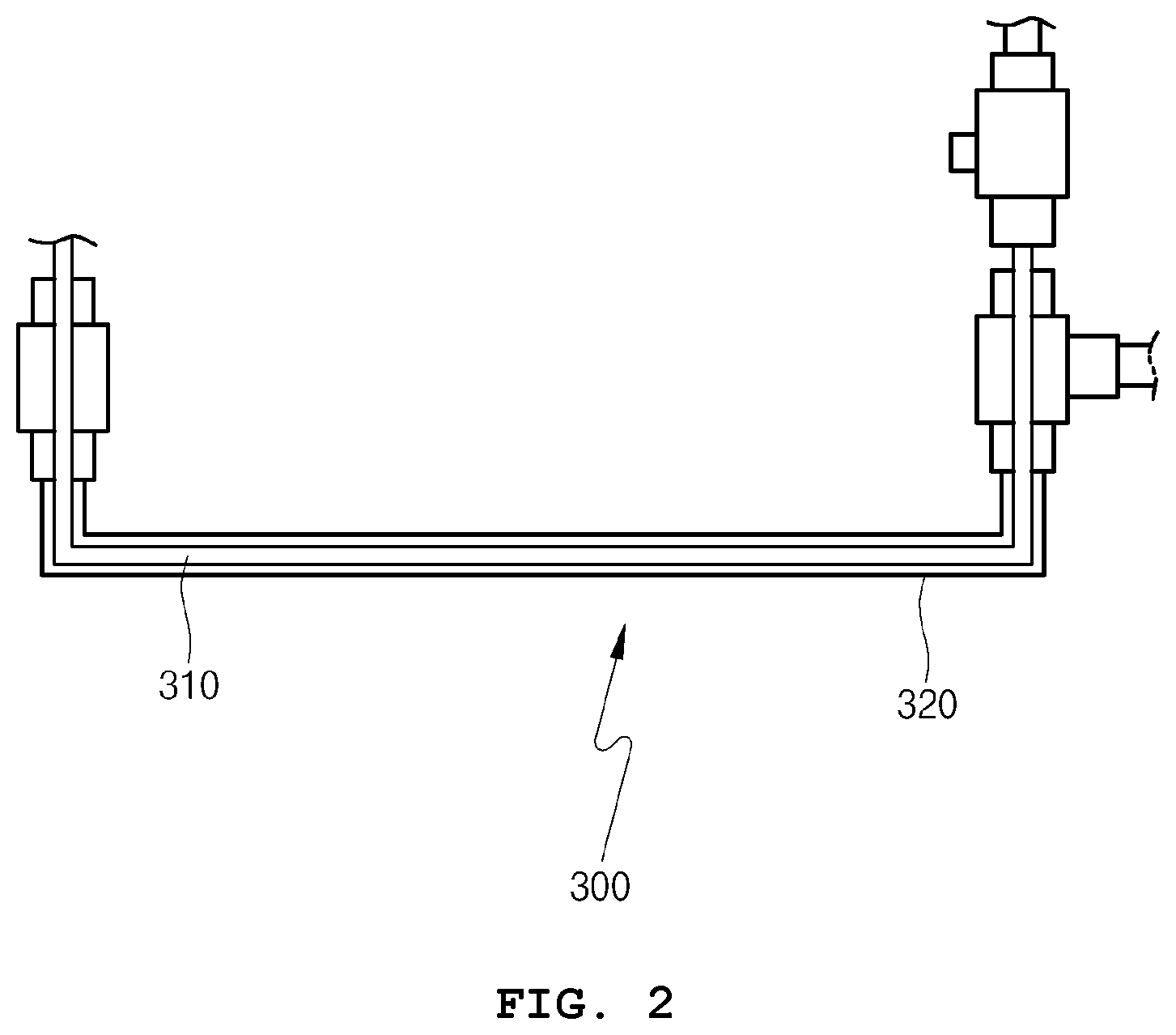
FIG. 3 is a perspective view illustrating a specimen rack of the temperature maintaining device according to the embodiment of the present invention; and
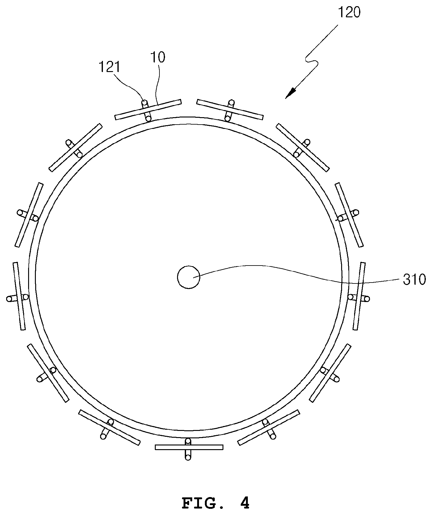
FIG. 4 is a plan view illustrating the temperature maintaining device according to the embodiment of the present invention.
DETAILED DESCRIPTION
In the following description, the specific structural or functional descriptions for exemplary embodiments according to the concept of the present disclosure are merely for illustrative purposes and those skilled in the art will appreciate that various modifications and changes to the exemplary embodiments are possible, without departing from the scope and spirit of the present invention. Therefore, the present invention is intended to cover not only the exemplary embodiments but also various alternatives, modifications, equivalents, and other embodiments that may be included within the spirit and scope of the embodiments as defined by the appended claims.
Hereinbelow, exemplary embodiments of the present disclosure will be described in detail with reference to the accompanying drawings.
FIG. 1 is a cross-sectional view illustrating a device for maintaining the internal temperature of a pressure vessel at a constant level. The device includes: a pressure vessel 100 equipped with a main heater 110 for heating test water to a predetermined test temperature so that the test water can be maintained at the predetermined test temperature; a preheater 200 for heating the test water to the predetermined test temperature before the main heater 110 heats the test water; and a heat exchanger 300 including a feed pipe 310 for feeding the test water heated by the preheater 200 to the pressure vessel 100 and a discharge pipe 320 for transporting the test water discharged from the pressure vessel 100, in which the feed pipe 310 is disposed inside the discharge pipe 320.
The preheater 200 has a pipe through which the test water flows. The preheater 200 heats the pipe while the test water flows along the pipe, thereby primarily increasing the temperature of the test water. The pipe is formed in a zigzag shape so that the test water can be heated to the predetermined test temperature while the test water flows along the pipe provided inside the preheater.
The pressure vessel 100 is equipped with the main heater 110 for complementing for the heat loss that is incurred until the test water heated by the preheater 200 reaches the pressure vessel 100. That is, the main heater 110 raises the temperature of the test water to the predetermined test temperature again.
The inside of the pressure vessel 100 is provided with a cylindrical specimen holding rack 120 by which a plurality of specimens can be held. The specimen holding rack 120 has a plurality of rings or hooks 121 for holding respective specimens 10.
The heat exchanger 300 includes the feed pipe 310 for feeding the test water that is heated primarily by the preheater 200 to the pressure vessel 100 and the discharge pipe 320 through which the used test water is discharged from the pressure vessel 100. The feed pipe 310 is disposed inside the discharge pipe 320.
FIG. 2 is an enlarged view of the heat exchanger of the pressure holding device according to the embodiment of the present invention. In the heat exchanger 300, the feed pipe 310 is installed to extend through the discharge pipe 320. Therefore, until the primarily heated test water reaches to the pressure vessel by flowing through the feed pipe 310, the discharge pipe 320 filled with the test water discharged from the pressure vessel prevents the heat loss of the test water that is fed to the pressure vessel through the feed pipe 310.
The feed pipe 310 is inserted into the pressure vessel 100 from the bottom side and is installed to extend up to an upper portion of the pressure vessel 100. This piping design of the feed pipe 310 is to prevent a phenomenon in which the upper part of the pressure vessel is higher in temperature than the lower part due to the density difference of the test water attributable to the temperature difference. That is, this piping design enables the test water passing through the feed pipe 310 to be first supplied to the upper part of the pressure vessel 100, which suppress the temperature rising in the upper part and reducing the temperature difference between the upper part and the lower part of the pressure vessel 100.
This piping design is also advantageous in terms that even though there is a chance that the test water transported through the feed pipe 310 experiences heat loss before reaching the pressure vessel 100, the test water can be further heated while moving from the bottom side to the top side of the pressure vessel through the feed pipe 310. Therefore, it is possible to ensure the reliable control of the test temperature of the test water.
The discharge pipe 320 is connected to the bottom side of the pressure vessel 100 while concentrically surrounding the feed pipe 310. Thus, the test water having a relatively low temperature as a result of circulating through the inside of the pressure vessel 100 is discharged through the discharge pipe 320. This facilitates circulation of the test water in the pressure vessel 100.
FIG. 3 is a perspective view of the specimen holding rack installed in the pressure vessel. The specimen holding rack 120 is a columnar frame composed of multiple circular frames that are arranged in a vertical direction at a predetermined interval.
Each of the circular frames has a plurality of hooks 121 used to hang the specimens 10. Therefore, it is easy to mount the specimens 10. In addition, since the circular frames are spaced apart from each other by a predetermined distance in the vertical direction, it is possible to prevent the specimens 10 from colliding or overlapping with each other when mounted to the specimen holding rack.
FIG. 4 is a plan view of the specimen holding rack to be installed in a pressure vessel. The discharge pipe 320 is positioned at the center of the specimen holding rack 120.
By controlling the temperature of the test water discharged from the pressure vessel 100 through the discharge pipe 320, the internal temperature of the pressure vessel 100 can be maintained at a predetermined constant level, and accurate test data can be obtained from the plurality of specimens 10.
Although the preferred embodiments of the present disclosure have been disclosed for illustrative purposes, those skilled in the art will appreciate that various modifications, additions and substitutions are possible, without departing from the scope and spirit of the invention as disclosed in the accompanying claims.
TABLE-US-00001 [Explanation of Reference Numerals] 10: Specimen 100: Pressure vessel 110: Main heater 120: Specimen rack 121: Ring 200: Preheater 300: Heat exchanger 310: Feed pipe 320: Discharge pipe
* * * * *
D00000
D00001
D00002
D00003
D00004
XML
uspto.report is an independent third-party trademark research tool that is not affiliated, endorsed, or sponsored by the United States Patent and Trademark Office (USPTO) or any other governmental organization. The information provided by uspto.report is based on publicly available data at the time of writing and is intended for informational purposes only.
While we strive to provide accurate and up-to-date information, we do not guarantee the accuracy, completeness, reliability, or suitability of the information displayed on this site. The use of this site is at your own risk. Any reliance you place on such information is therefore strictly at your own risk.
All official trademark data, including owner information, should be verified by visiting the official USPTO website at www.uspto.gov. This site is not intended to replace professional legal advice and should not be used as a substitute for consulting with a legal professional who is knowledgeable about trademark law.