Insulated box
Waltermire , et al. February 2, 2
U.S. patent number 10,906,724 [Application Number 15/590,349] was granted by the patent office on 2021-02-02 for insulated box. This patent grant is currently assigned to Pratt Retail Specialties, LLC. The grantee listed for this patent is Pratt Retail Specialties, LLC. Invention is credited to Paul Ott, Greg Sollie, Jamie Waltermire.


View All Diagrams
| United States Patent | 10,906,724 |
| Waltermire , et al. | February 2, 2021 |
Insulated box
Abstract
An insulated box includes a box, the box including a bottom panel and a side panel, the side panel attached to the bottom panel; and an insulated panel attached to the side panel, the insulated panel including an insulation batt and a sheet, the insulation batt enclosed between the side panel and the sheet.
| Inventors: | Waltermire; Jamie (Peachtree City, GA), Ott; Paul (Atlanta, GA), Sollie; Greg (Sharpsburg, GA) | ||||||||||
|---|---|---|---|---|---|---|---|---|---|---|---|
| Applicant: |
|
||||||||||
| Assignee: | Pratt Retail Specialties, LLC
(Conyers, GA) |
||||||||||
| Family ID: | 1000005334625 | ||||||||||
| Appl. No.: | 15/590,349 | ||||||||||
| Filed: | May 9, 2017 |
Prior Publication Data
| Document Identifier | Publication Date | |
|---|---|---|
| US 20180327171 A1 | Nov 15, 2018 | |
| Current U.S. Class: | 1/1 |
| Current CPC Class: | B65D 25/287 (20130101); B65D 81/3858 (20130101); B65D 5/0065 (20130101); B65D 1/24 (20130101); B65D 5/001 (20130101); B65D 2525/281 (20130101); B65D 11/1806 (20130101); B65D 81/3848 (20130101) |
| Current International Class: | B65D 81/38 (20060101); B65D 5/00 (20060101); B65D 1/24 (20060101); B65D 25/28 (20060101); B65D 6/18 (20060101) |
| Field of Search: | ;220/592.24,592.2 ;206/521,523,545 |
References Cited [Referenced By]
U.S. Patent Documents
| 265985 | October 1882 | Seabury |
| 1527167 | February 1925 | Birdseye |
| 1677565 | July 1928 | Oppenheim |
| 1682410 | August 1928 | Oppenheim |
| 1747980 | February 1930 | Kondolf |
| 1753813 | April 1930 | Washburn |
| 1868996 | July 1932 | Sharp |
| 1896393 | February 1933 | Devine |
| 1899892 | February 1933 | D'Este et al. |
| 1930680 | October 1933 | Hinton |
| 1935923 | November 1933 | Thoke |
| 1937263 | November 1933 | Bubb |
| 1942917 | January 1934 | D'Este et al. |
| 1954013 | April 1934 | Lilienfield |
| 2018519 | October 1935 | Hall |
| 2070747 | February 1937 | Ostrom |
| 2116513 | May 1938 | Frankenstein |
| 2148454 | February 1939 | Gerard |
| 2165327 | July 1939 | Zalkind |
| 2289060 | July 1942 | Merkle |
| 2293361 | August 1942 | Roberts |
| 2360806 | October 1944 | Van Rosen |
| 2386905 | October 1945 | Meitzen |
| 2389601 | November 1945 | De Witt |
| 2485643 | October 1949 | Norquist |
| 2554004 | May 1951 | Bergstein |
| 2632311 | March 1953 | Sullivan |
| 2650016 | August 1953 | McMillan |
| 2753102 | July 1956 | Paige |
| 2899103 | August 1959 | Ebert |
| 2927720 | March 1960 | Adams |
| 2987239 | June 1961 | Atwood |
| 3029008 | April 1962 | Membrino |
| 3031121 | April 1962 | Chase |
| 3065895 | November 1962 | Lipschutz |
| 3096879 | July 1963 | Schumacher |
| 3097782 | July 1963 | Koropatkin et al. |
| 3182913 | May 1965 | Brian |
| 3193176 | July 1965 | Gullickson et al. |
| 3222843 | December 1965 | Schneider |
| 3236206 | February 1966 | Willinger |
| 3282411 | November 1966 | Jardine |
| 3286825 | November 1966 | Laas |
| 3335941 | August 1967 | Gatward |
| 3371462 | March 1968 | Nordkvist |
| 3375934 | April 1968 | Bates |
| 3420363 | January 1969 | Blickensderfer |
| 3435736 | April 1969 | Reiche |
| 3503550 | March 1970 | Main et al. |
| 3551945 | January 1971 | Eyberg et al. |
| 3670948 | June 1972 | Berg |
| 3703383 | November 1972 | Kuchenbecker |
| 3734336 | May 1973 | Rankow et al. |
| 3747743 | July 1973 | Hoffman, Jr. |
| 3749299 | July 1973 | Ingle |
| 3836044 | September 1974 | Tilp et al. |
| 3843038 | October 1974 | Sax |
| 3880341 | April 1975 | Bamburg et al. |
| 3887743 | June 1975 | Lane |
| 3890762 | June 1975 | Ernst |
| 3980005 | September 1976 | Buonaiuto |
| 4030227 | June 1977 | Oftedahl |
| 4050264 | September 1977 | Tanaka |
| 4068779 | January 1978 | Canfield |
| 4091852 | May 1978 | Jordan et al. |
| 4169540 | October 1979 | Larsson et al. |
| 4211267 | July 1980 | Skovgaard |
| 4213310 | July 1980 | Buss |
| 4335844 | June 1982 | Egli |
| 4342416 | August 1982 | Philips |
| 4380314 | April 1983 | Langston, Jr. et al. |
| 4396144 | August 1983 | Gutierrez et al. |
| 4418864 | December 1983 | Neilsen |
| 4488623 | December 1984 | Linnell, II et al. |
| 4509645 | April 1985 | Hotta |
| 4679242 | July 1987 | Brockhaus |
| 4682708 | July 1987 | Pool |
| 4797010 | January 1989 | Coelho |
| 4819793 | April 1989 | Willard et al. |
| 4828133 | May 1989 | Hougendobler |
| 4830282 | May 1989 | Knight, Jr. |
| 4889252 | December 1989 | Rockom et al. |
| 4930903 | June 1990 | Mahoney |
| 4989780 | February 1991 | Foote et al. |
| 5016813 | May 1991 | Simons |
| 5020481 | June 1991 | Nelson |
| 5062527 | November 1991 | Westerman |
| 5094547 | March 1992 | Graham |
| 5102004 | April 1992 | Hollander et al. |
| 5154309 | October 1992 | Wischusen, III |
| 5158371 | October 1992 | Moravek |
| 5165583 | November 1992 | Kouwenberg |
| 5185904 | February 1993 | Rogers et al. |
| 5230450 | July 1993 | Mahvi et al. |
| 5263339 | November 1993 | Evans |
| 5358757 | October 1994 | Robinette et al. |
| 5372429 | December 1994 | Beaver, Jr. et al. |
| 5417342 | May 1995 | Hutchison |
| 5418031 | May 1995 | English |
| 5441170 | August 1995 | Bane, III |
| 5454471 | October 1995 | Norvell |
| 5491186 | February 1996 | Kean et al. |
| 5493874 | February 1996 | Landgrebe |
| 5499473 | March 1996 | Ramberg |
| 5505810 | April 1996 | Kirby |
| 5511667 | April 1996 | Carder |
| 5512345 | April 1996 | Tsutsumi |
| 5516580 | May 1996 | Frenette et al. |
| 5562228 | October 1996 | Ericson |
| 5573119 | November 1996 | Luray |
| 5596880 | January 1997 | Welker et al. |
| 5613610 | March 1997 | Bradford |
| 5615795 | April 1997 | Tipps |
| 5638978 | June 1997 | Cadiente |
| 5775576 | July 1998 | Stone |
| 5842571 | December 1998 | Rausch |
| 5906290 | May 1999 | Haberkorn |
| 5996366 | December 1999 | Renard |
| 6003719 | December 1999 | Stewart, III |
| 6041958 | March 2000 | Tremelo |
| 6048099 | April 2000 | Muffett et al. |
| 6050412 | April 2000 | Clough et al. |
| 6138902 | October 2000 | Welch |
| 6164526 | December 2000 | Dalvey |
| 6168040 | January 2001 | Sautner et al. |
| 6220473 | April 2001 | Lehman et al. |
| 6223551 | May 2001 | Mitchell |
| 6238091 | May 2001 | Mogil |
| 6244458 | June 2001 | Frysinger et al. |
| 6247328 | June 2001 | Mogil |
| 6295830 | October 2001 | Newman |
| 6295860 | October 2001 | Sakairi et al. |
| 6308850 | October 2001 | Coom et al. |
| 6325281 | December 2001 | Grogan |
| 6443309 | September 2002 | Becker |
| 6453682 | September 2002 | Jennings et al. |
| 6478268 | November 2002 | Bidwell et al. |
| 6510705 | January 2003 | Jackson |
| 6582124 | June 2003 | Mogil |
| 6618868 | September 2003 | Minnick |
| 6688133 | February 2004 | Donefrio |
| 6725783 | April 2004 | Sekino |
| 6726017 | April 2004 | Maresh et al. |
| 6736309 | May 2004 | Westerman et al. |
| 6771183 | August 2004 | Hunter |
| 6821019 | November 2004 | Mogil |
| 6837420 | January 2005 | Westerman et al. |
| 6868982 | March 2005 | Gordon |
| 6875486 | April 2005 | Miller |
| 6899229 | May 2005 | Dennison et al. |
| 6910582 | June 2005 | Lantz |
| 6913389 | July 2005 | Kannankeril et al. |
| 6971539 | December 2005 | Abbe |
| 7000962 | February 2006 | Le |
| 7019271 | March 2006 | Wnek et al. |
| 7094192 | August 2006 | Schoenberger et al. |
| 7140773 | November 2006 | Becker et al. |
| 7225632 | June 2007 | Derifield |
| 7225970 | June 2007 | Philips |
| 7229677 | June 2007 | Miller |
| 7264147 | September 2007 | Benson et al. |
| 7392931 | July 2008 | Issler |
| 7452316 | November 2008 | Cals et al. |
| D582676 | December 2008 | Rothschild |
| 7597209 | October 2009 | Rothschild et al. |
| 7607563 | October 2009 | Hanna et al. |
| 7677406 | March 2010 | Maxson |
| 7681405 | March 2010 | Williams |
| 7784301 | August 2010 | Sasaki et al. |
| 7807773 | October 2010 | Matsuoka et al. |
| 7841512 | November 2010 | Westerman et al. |
| 7845508 | December 2010 | Rothschild et al. |
| 7870992 | January 2011 | Schille et al. |
| 7909806 | March 2011 | Goodman et al. |
| 7971720 | July 2011 | Minkler |
| 8118177 | February 2012 | Drapela et al. |
| 8209995 | July 2012 | Kieling et al. |
| 8343024 | January 2013 | Contanzo, Jr. et al. |
| 8365943 | February 2013 | Bentley |
| 8465404 | June 2013 | Hadley |
| 8579183 | November 2013 | Belfort et al. |
| 8596520 | December 2013 | Scott |
| 8613202 | December 2013 | Williams |
| 8651593 | February 2014 | Bezich et al. |
| 8763811 | July 2014 | Lantz |
| 8763886 | July 2014 | Hall |
| 8795470 | August 2014 | Henderson et al. |
| 8919082 | December 2014 | Cataldo |
| 8960528 | February 2015 | Sadlier |
| 9272475 | March 2016 | Ranade et al. |
| 9290313 | March 2016 | De Lesseux et al. |
| 9322136 | April 2016 | Ostendorf et al. |
| D758182 | June 2016 | Sponselee |
| 9408445 | August 2016 | Mogil et al. |
| 9429350 | August 2016 | Chapman, Jr. |
| 9499294 | November 2016 | Contanzo, Jr. |
| 9550618 | January 2017 | Jobe |
| 9605382 | March 2017 | Virtanen |
| 9611067 | April 2017 | Collison |
| 9635916 | May 2017 | Bezich et al. |
| 9701437 | July 2017 | Bugas et al. |
| 9738420 | August 2017 | Miller |
| 9738432 | August 2017 | Petrucci et al. |
| 9834366 | December 2017 | Giuliani |
| 9908680 | March 2018 | Shi et al. |
| 9908684 | March 2018 | Collison |
| 9920517 | March 2018 | Sollie |
| 9950830 | April 2018 | De Lesseux et al. |
| 9981797 | May 2018 | Aksan et al. |
| 10046901 | August 2018 | Jobe |
| 10094126 | October 2018 | Collison et al. |
| 10112756 | October 2018 | Menzel, Jr. |
| 10226909 | March 2019 | Frem et al. |
| 10266332 | April 2019 | Aksan et al. |
| 10357936 | July 2019 | Vincent et al. |
| 10442600 | October 2019 | Waltermire et al. |
| 10507968 | December 2019 | Sollie et al. |
| 10551110 | February 2020 | Waltermire et al. |
| 10583977 | March 2020 | Collison et al. |
| 10800595 | October 2020 | Waltermire et al. |
| 2001/0010312 | August 2001 | Mogil |
| 2002/0020188 | February 2002 | Sharon et al. |
| 2002/0162767 | November 2002 | Ohtsubo |
| 2003/0145561 | August 2003 | Cals et al. |
| 2004/0004111 | January 2004 | Cardinale |
| 2004/0031842 | February 2004 | Westerman et al. |
| 2004/0079794 | April 2004 | Mayer |
| 2005/0109655 | May 2005 | Vershum et al. |
| 2005/0117817 | June 2005 | Mogil et al. |
| 2005/0189404 | September 2005 | Xiaohai et al. |
| 2005/0214512 | September 2005 | Fascio |
| 2005/0224501 | October 2005 | Folkert et al. |
| 2005/0279963 | December 2005 | Church et al. |
| 2006/0053828 | March 2006 | Shallman et al. |
| 2006/0078720 | April 2006 | Toas et al. |
| 2006/0096978 | May 2006 | Lafferty et al. |
| 2006/0193541 | August 2006 | Norcom |
| 2007/0000932 | January 2007 | Cron |
| 2007/0000983 | January 2007 | Spurrell et al. |
| 2007/0051782 | March 2007 | Lantz |
| 2007/0193298 | August 2007 | Derifield |
| 2007/0209307 | September 2007 | Andersen |
| 2007/0257040 | November 2007 | Price, Jr. et al. |
| 2008/0095959 | April 2008 | Warner et al. |
| 2008/0135564 | June 2008 | Romero |
| 2008/0173703 | July 2008 | Westerman et al. |
| 2008/0190940 | August 2008 | Scott |
| 2008/0203090 | August 2008 | Dickinson |
| 2008/0289302 | November 2008 | Vulpitta |
| 2008/0296356 | December 2008 | Hatcher et al. |
| 2008/0308616 | December 2008 | Phung |
| 2008/0314794 | December 2008 | Bowman |
| 2009/0034883 | February 2009 | Giuliani |
| 2009/0114311 | May 2009 | McDowell |
| 2009/0193765 | August 2009 | Lantz |
| 2009/0214142 | August 2009 | Bossel et al. |
| 2009/0283578 | November 2009 | Miller |
| 2009/0288791 | November 2009 | Hammer et al. |
| 2010/0001056 | January 2010 | Chandaria |
| 2010/0006630 | January 2010 | Humphries et al. |
| 2010/0062921 | March 2010 | Veiseh |
| 2010/0072105 | March 2010 | Glaser et al. |
| 2010/0139878 | June 2010 | Clemente |
| 2010/0151164 | June 2010 | Grant et al. |
| 2010/0258574 | October 2010 | Bentley |
| 2010/0270317 | October 2010 | Kieling et al. |
| 2010/0282827 | November 2010 | Padovani |
| 2010/0284634 | November 2010 | Hadley |
| 2010/0314397 | December 2010 | Williams et al. |
| 2010/0314437 | December 2010 | Dowd |
| 2011/0042449 | February 2011 | Copenhaver |
| 2011/0100868 | May 2011 | Lantz |
| 2011/0114513 | May 2011 | Miller |
| 2011/0235950 | September 2011 | Lin |
| 2011/0284556 | November 2011 | Palmer et al. |
| 2011/0311758 | December 2011 | Burns et al. |
| 2011/0317944 | December 2011 | Liu |
| 2012/0031957 | February 2012 | Whitaker |
| 2012/0074823 | March 2012 | Bezich et al. |
| 2012/0145568 | June 2012 | Collison et al. |
| 2012/0243808 | September 2012 | De Lesseux et al. |
| 2012/0248101 | October 2012 | Tumber et al. |
| 2012/0251818 | October 2012 | Axrup et al. |
| 2012/0279896 | November 2012 | Lantz |
| 2013/0112694 | May 2013 | Bentley |
| 2013/0112695 | May 2013 | Hall |
| 2013/0140317 | June 2013 | Roskoss |
| 2014/0000306 | January 2014 | Chapman, Jr. |
| 2014/0021208 | January 2014 | Anti et al. |
| 2014/0093697 | April 2014 | Perry et al. |
| 2014/0248003 | September 2014 | Mogil et al. |
| 2014/0319018 | October 2014 | Collison |
| 2014/0367393 | December 2014 | Ranade |
| 2015/0110423 | April 2015 | Fox et al. |
| 2015/0166244 | June 2015 | Wood et al. |
| 2015/0175338 | June 2015 | Culp et al. |
| 2015/0238033 | August 2015 | Zavitsanos |
| 2015/0239639 | August 2015 | Wenner et al. |
| 2015/0259126 | September 2015 | McGoff et al. |
| 2015/0284131 | October 2015 | Genender et al. |
| 2015/0345853 | December 2015 | Oeyen |
| 2016/0015039 | January 2016 | Pierce |
| 2016/0052696 | February 2016 | Cook et al. |
| 2016/0060017 | March 2016 | De Lesseux et al. |
| 2016/0304267 | October 2016 | Aksan |
| 2016/0325915 | November 2016 | Aksan |
| 2017/0015080 | January 2017 | Collison et al. |
| 2017/0043937 | February 2017 | Lantz |
| 2017/0198959 | July 2017 | Morris |
| 2017/0225870 | August 2017 | Collison |
| 2017/0233134 | August 2017 | Grajales et al. |
| 2017/0283157 | October 2017 | Jobe |
| 2017/0305639 | October 2017 | Kuhn et al. |
| 2017/0320653 | November 2017 | Mogil et al. |
| 2017/0334622 | November 2017 | Menzel, Jr. |
| 2017/0341847 | November 2017 | Chase |
| 2017/0369226 | December 2017 | Chase et al. |
| 2018/0050857 | February 2018 | Collison |
| 2018/0051460 | February 2018 | Sollie et al. |
| 2018/0148246 | May 2018 | Fu et al. |
| 2018/0194534 | July 2018 | Jobe |
| 2018/0215525 | August 2018 | Vogel et al. |
| 2018/0229917 | August 2018 | Jobe |
| 2018/0237207 | August 2018 | Aksan et al. |
| 2018/0274837 | September 2018 | Christensen |
| 2018/0290813 | October 2018 | Waltermire et al. |
| 2018/0290815 | October 2018 | Waltermire et al. |
| 2018/0299059 | October 2018 | McGoff et al. |
| 2018/0327172 | November 2018 | Waltermire et al. |
| 2018/0334308 | November 2018 | Moore et al. |
| 2018/0335241 | November 2018 | Li et al. |
| 2019/0032991 | January 2019 | Waltermire et al. |
| 2019/0047775 | February 2019 | Waltermire et al. |
| 2019/0185246 | June 2019 | Sollie et al. |
| 2019/0185247 | June 2019 | Sollie et al. |
| 2019/0193916 | June 2019 | Waltermire et al. |
| 2019/0210790 | July 2019 | Rizzo et al. |
| 2019/0234679 | August 2019 | Waltermire et al. |
| 2019/0248573 | August 2019 | Collison et al. |
| 2019/0270572 | September 2019 | Collison et al. |
| 2019/0270573 | September 2019 | Collison et al. |
| 2019/0352075 | November 2019 | Waltermire et al. |
| 2019/0352076 | November 2019 | Waltermire et al. |
| 2019/0352080 | November 2019 | Waltermire et al. |
| 2019/0359412 | November 2019 | Sollie et al. |
| 2019/0359413 | November 2019 | Sollie et al. |
| 2019/0359414 | November 2019 | Sollie et al. |
| 2019/0367209 | December 2019 | Jobe |
| 2019/0376636 | December 2019 | Fellinger et al. |
| 2019/0382186 | December 2019 | Sollie et al. |
| 2019/0390892 | December 2019 | Waltermire et al. |
| 2020/0088458 | March 2020 | Waltermire et al. |
| 2020/0103159 | April 2020 | Waltermire et al. |
| 2020/0122896 | April 2020 | Waltermire et al. |
| 2020/0148409 | May 2020 | Sollie et al. |
| 2020/0148410 | May 2020 | Sollie et al. |
| 2020/0148453 | May 2020 | Sollie et al. |
| 2020/0283188 | September 2020 | Sollie et al. |
| 2020/0346816 | November 2020 | Sollie et al. |
| 2020/0346841 | November 2020 | Sollie et al. |
| 2019104 | Dec 1991 | CA | |||
| 206494316 | Sep 2017 | CN | |||
| 108001787 | May 2018 | CN | |||
| 1897846 | Jul 1964 | DE | |||
| 102011016500 | Oct 2012 | DE | |||
| 202017103230 | Jul 2017 | DE | |||
| 202017003908 | Oct 2017 | DE | |||
| 0133539 | Feb 1985 | EP | |||
| 0537058 | Apr 1993 | EP | |||
| 2990196 | Mar 2016 | EP | |||
| 1241878 | Sep 1960 | FR | |||
| 2705317 | Nov 1994 | FR | |||
| 2820718 | Aug 2002 | FR | |||
| 2821786 | Sep 2002 | FR | |||
| 3016352 | Jul 2015 | FR | |||
| 217683 | Jun 1924 | GB | |||
| 235673 | Jun 1925 | GB | |||
| 528289 | Jan 1940 | GB | |||
| 713640 | Aug 1954 | GB | |||
| 1204058 | Sep 1970 | GB | |||
| 1305212 | Jan 1973 | GB | |||
| 1372054 | Oct 1974 | GB | |||
| 2400096 | May 2006 | GB | |||
| 2516490 | Jan 2015 | GB | |||
| 01254557 | Oct 1989 | JP | |||
| 2005139582 | Jun 2005 | JP | |||
| 2005247329 | Sep 2005 | JP | |||
| 2012126440 | Jul 2012 | JP | |||
| 8807476 | Oct 1988 | WO | |||
| 9726192 | Jul 1997 | WO | |||
| 9932374 | Jul 1999 | WO | |||
| 2001070592 | Sep 2001 | WO | |||
| 2014147425 | Sep 2014 | WO | |||
| 2016187435 | May 2016 | WO | |||
| 2016187435 | Nov 2016 | WO | |||
| 2018089365 | May 2018 | WO | |||
| 2018093586 | May 2018 | WO | |||
| 2018227047 | Dec 2018 | WO | |||
| 2019125904 | Jun 2019 | WO | |||
| 2019125906 | Jun 2019 | WO | |||
| 2019226199 | Nov 2019 | WO | |||
| 2020101939 | May 2020 | WO | |||
| 2020102023 | May 2020 | WO | |||
| 2020122921 | Jun 2020 | WO | |||
| 2020222943 | Nov 2020 | WO | |||
Other References
|
US 10,562,676 B2, 02/2020, Waltermire et al. (withdrawn) cited by applicant . Waltermire, Jamie; Non-Final Office Action for U.S. Appl. No. 15/590,345, filed May 9, 2017, dated Aug. 24, 2018, 41 pgs. cited by applicant . Collison, Alan B.; Requirement for Restriction/Election for U.S. Appl. No. 15/677,738, filed Aug. 15, 2017, dated Jul. 3, 2018, 8 pgs. cited by applicant . Collison, Alan B.; Requirement for Restriction/Election for U.S. Appl. No. 15/677,738, filed Aug. 15, 2017, dated Jul. 31, 2018, 8 pgs. cited by applicant . Cold Keepers; Article entitled: "Insulated Shipping Boxes--Coldkeepers, Thermal Shipping Solutions", located at <https://www.coldkeepers.com/product-category/shipping/>, (Accessed: Jan. 12, 2017), 3 pgs. cited by applicant . Needles `N` Knowledge; Article entitled: "Tall Box With Lid", located at <http://needlesnknowledge.blogspot.com/2017/10/tall-box-with-lid.html&- gt; (Accessed: Jan. 12, 2017), 10 pgs. cited by applicant . Salazar Packaging; Article entitle: "Custom Packaging and Design", located at <https://salazarpackaging.com/custom-packaging-and-design/>, accessed on Sep. 28, 2017, 2 pgs. cited by applicant . weiku.com; Article entitled: "100% Biodegradable Packing materials Green Cell Foam Stock Coolers", located at http://www.weiku.com/products/18248504/100_Biodegradable_Packing_material- s_Green_Cell_Foam_Stock_Coolers.html>, accessed on Sep. 28, 2017, 7 pgs. cited by applicant . Waltermire, Jamie; Non-Final Office Action for U.S. Appl. No. 15/482,200, filed Apr. 7, 2017, dated Jun. 11, 2018, 36 pgs. cited by applicant . MP Global Products, LLC; International Search Report and Written Opinion of the International Searching Authority for PCT/US2017/060403, filed Nov. 7,2017, dated Feb. 19, 2018, 15 pgs. cited by applicant . Greenblue; "Environmental Technical Briefs of Common Packaging Materials--Fiber-Based Materials", Sustainable Packaging Solution, 2009, 19 pgs. cited by applicant . MP Global Products; Article entitled: "Thermopod mailer envelopes and Thermokeeper insulated box liners", located at < http://www.mhpn.com/product/thermopod_mailer_envelopes_and_thermokeeper_i- nsulated_box_liners/packaging>, accessed on Aug. 30, 2017, 2 pgs. cited by applicant . UN Packaging; Article entitled: "CooLiner.RTM. Insulated Shipping Bags", available at <http://www.chem-tran.com/packaging/supplies/cooliner-insulated-shippi- ng-bags.php>, accessed on Aug. 30, 2017, 2 pgs. cited by applicant . American Bag Company; Article entitled: "Cool Green Bag, Small", located at <http://hotcoldbags.com/items/Cool%20Green%20Bag,%20Small>, accessed on Mar. 20, 2017, 2 pgs. cited by applicant . Duro Bag; Article entitled: "The Load and Fold Bag", accessed on May 24, 2017, copyrighted Apr. 2017, 3 pgs. cited by applicant . Images of Novolex bag, including an outer paper bag, a corrugated cardboard insert, and an inner foil-covered bubble-wrap bag, publicly available prior to May 9, 2017, 7 pgs. cited by applicant . Tera-Pak; Article entitled: "Insulated Shipping Containers", located at <http://www.tera-pak.com/>, accessed on Mar. 20, 2017, 3 pgs. cited by applicant . Waltermire, Jamie; Final Office Action for U.S. Appl. No. 15/590,345, filed May 9, 2017, dated Mar. 19, 2019, 42 pgs. cited by applicant . Waltermire, Jamie; Requirement for Restriction/Election for U.S. Appl. No. 15/663,905, filed Jul. 31, 2017, dated Mar. 21, 2019, 8 pgs. cited by applicant . Sollie, Greg; Non-Final Office Action for U.S. Appl. No. 15/845,545, filed Dec. 18, 2017, dated Mar. 5, 2019, 41 pgs. cited by applicant . Sollie, Greg; Non-Final Office Action for U.S. Appl. No. 15/845,540, filed Dec. 18, 2017, dated Apr. 2, 2019, 50 pgs. cited by applicant . Collison, Alan B.; Final Office Action for U.S. Appl. No. 15/677,738, filed Aug. 15, 2017, dated Feb. 28, 2019, 14 pgs. cited by applicant . Cellulose Material Solutions, LLC; Brochure for Infinity Care Thermal Liner, accessed on Oct. 22, 2018, 2 pgs. cited by applicant . Uline; Article entitled: Corrugated Corner Protectors--4 .times. 4'', accessed on Oct. 25, 2018, 1 pg. cited by applicant . DHL Express; Brochure for Dry Ice Shipping Guidelines, accessed on Oct. 26, 2018, 12 pgs. cited by applicant . Thomas Scientific; Article entitled: "Thermosafe: Test Tube Shipper/Rack", accessed on Oct. 26, 2018, 2 pgs. cited by applicant . Stinson, Elizabeth; Article entitled: "A Pizza Geek Discovers the World's Smartest Pizza Box", published Jan. 17, 2014, 8 pgs. cited by applicant . Waltermire, Jamie; International Search Report and Written Opinion for PCT Application No. PCT/US18/65464, filed Dec. 13, 2018, dated Mar. 11, 2019, 9 pgs. cited by applicant . Sollie, Greg; International Search Report and Written Opinion for PCT Application No. PCT/US18/65461, filed Dec. 13, 2018, dated Mar. 21, 2019, 13 pgs. cited by applicant . Sollie, Greg; International Search Report and Written Opinion for PCT/US18/65463, filed Dec. 13, 2018, dated Mar. 25, 2019, 11 pgs. cited by applicant . Waltermire, Jamie; Requirement for Restriction/Election for U.S. Appl. No. 15/482,186, filed Apr. 7, 2017, dated Apr. 17, 2019, 7 pgs. cited by applicant . Collison, Alan B.; Applicant Interview Summary for U.S. Appl. No. 15/677,738, filed Aug. 15, 2017, dated Apr. 22, 2019, 4 pgs. cited by applicant . Waltermire, Jamie; Final Office Action for U.S. Appl. No. 15/482,200, filed Apr. 7, 2017, dated Jan. 2, 2019, 23 pgs. cited by applicant . Collison, Alan B.; Applicant Interview Summary for U.S. Appl. No. 15/677,738, filed Aug. 15, 2017, dated Dec. 5, 2018, 4 pgs. cited by applicant . Collison, Alan B.; Non-Final Office Action for U.S. Appl. No. 15/677,738, filed Aug. 15, 2017, dated Oct. 23, 2018, 11 pgs. cited by applicant . PERIWRAP; Article entitled: "Insulated Solutions", located at <https://www.peri-wrap.com/insulation/>, accessed on Dec. 3, 2018, 5 pgs. cited by applicant . Singh, et al; Article entitled: "Performance Comparison of Thermal Insulated Packaging Boxes, Bags and Refrigerants for Single-parcel Shipments", published Mar. 13, 2007, 19 pgs. cited by applicant . PERIWRAP; Article entitled: "Insulated Solutions", located at <https://www.peri-wrap.com/insulation/>, accessed on Dec. 3, 2018, 9 pgs. cited by applicant . Waltermire, Jamie; Supplemental Notice of Allowance for U.S. Appl. No. 15/482,200, filed Apr. 7, 2017, dated Aug. 12, 2019, 7 pgs. cited by applicant . Waltermire, Jamie; Notice of Allowance for U.S. Appl. No. 15/482,200, filed Apr. 7, 2017, dated May 14, 2019, 25 pgs. cited by applicant . Waltermire, Jamie; Supplemental Notice of Allowance for U.S. Appl. No. 15/482,200, filed Apr. 7, 2017, dated Jul. 26, 2019, 9 pgs. cited by applicant . Waltermire, Jamie; Non-Final Office Action for U.S. Appl. No. 15/663,905, filed Jul. 31, 2017, dated May 25, 2019, 66 pgs. cited by applicant . Sollie, Greg; Notice of Allowance for U.S. Appl. No. 15/845,545, filed Dec. 18, 2017, dated Jun. 19, 2019, 20 pgs. cited by applicant . Collison, Alan B.; Corrected Notice of Allowance for U.S. Appl. No. 15/677,738, filed Aug. 15, 2017, dated Jul. 15, 2019, 7 pgs. cited by applicant . Collison, Alan B.; Notice of Allowance for U.S. Appl. No. 15/677,738, filed Aug. 15, 2017, dated Jun. 19, 2019, 10 pgs. cited by applicant . Sollie, Greg; Non-Final Office Action for U.S. Appl. No. 16/280,595, filed Feb. 20, 2019, dated May 29, 2019, 60 pgs. cited by applicant . Sollie, Greg; Requirement for Restriction/Election for U.S. Appl. No. 16/382,710, filed Apr. 12, 2019, dated Jul. 15, 2019, 6 pgs. cited by applicant . Sollie, Greg; International Search Report and Written Opinion for PCT Application No. PCT/US18/65459, filed Dec. 13, 2018, dated May 1, 2019, 15 pgs. cited by applicant . Voluntary Standard for Repulping and Recycling Corrugated Fiberboard Treated to Improve Its Performance in the Presence of Water and Water Vapor. (revises Aug. 16, 2013) Fibre Box Association (FBA), Elk Grove Village, IL, 1-23, Retrieved from http://www.corrugated.org/wp-content/uploads/PDFs/Recycling/Vol_Std_Proto- col_2013. pdf, 23 pgs. cited by applicant . Sollie, Greg; Non-Final Office Action for U.S. Appl. No. 15/988,550, filed May 24, 2018, dated May 29, 2019, 48 pgs. cited by applicant . Waltermire, Jamie; Non-Final Office Action for U.S. Appl. No. 15/482,186, filed Apr. 7, 2017, dated Aug. 20, 2019, 81 pgs. cited by applicant . Waltermire, Jamie; Supplemental Notice of Allowance for U.S. Appl. No. 15/482,200, filed Apr. 7, 2017, dated Sep. 10, 2019, 8 pgs. cited by applicant . Waltermire, Jamie; Notice of Allowance for U.S. Appl. No. 15/590,345, filed May 9, 2017, dated Oct. 1, 2019, 28 pgs. cited by applicant . Waltermire, Jamie; Final Office Action for U.S. Appl. No. 15/663,905, filed Jul. 31, 2017, dated Aug. 22, 2019, 23 pgs. cited by applicant . Waltermire, Jamie; Non-Final Office Action for U.S. Appl. No. 16/381,678, filed Apr. 11, 2019, dated Sep. 9, 2019, 50 pgs. cited by applicant . Sollie, Greg; Corrected Notice of Allowance for U.S. Appl. No. 15/845,545, filed Dec. 18, 2017, dated Oct. 1, 2019, 7 pgs. cited by applicant . Sollie, Greg; Final Office Action for U.S. Appl. No. 15/988,550, filed May 24, 2018, dated Aug. 14, 2019, 19 pgs. cited by applicant . Sollie, Greg; Non-Final Office Action for U.S. Appl. No. 15/988,550, filed May 24, 2018, dated Oct. 9, 2019, 17 pgs. cited by applicant . Sollie, Greg; Final Office Action for U.S. Appl. No. 16/280,595, filed Feb. 20, 2019, dated Oct. 3, 2019, 19 pgs. cited by applicant . Sollie, Greg; Non-Final Office Action for U.S. Appl. No. 16/530,052, filed Aug. 2, 2019, dated Oct. 2, 2019, 12 pgs. cited by applicant . Sollie, Greg; Non-Final Office Action for U.S. Appl. No. 16/408,981, filed May 10, 2019, dated Aug. 20, 2019, 50 pgs. cited by applicant . Sollie, Greg; Non-Final Office Action for U.S. Appl. No. 16/382,710, filed Apr. 12, 2019, dated Oct. 10, 2019, 49 pgs. cited by applicant . Waltermire, Jamie; Notice of Allowance for U.S. Appl. No. 15/482,186, filed Apr. 7, 2017, dated Mar. 5, 2020, 29 pgs. cited by applicant . Waltermire, Jamie; Corrected Notice of Allowance for U.S. Appl. No. 15/590,345, filed May 9, 2017, dated Feb. 18, 2020, 9 pgs. cited by applicant . Waltermire, Jamie; Supplemental Notice of Allowance for U.S. Appl. No. 15/590,345, filed May 9, 2017, dated Jan. 9, 2020, 8 pgs. cited by applicant . Waltermire, Jamie; Requirement for Restriction/Election for U.S. Appl. No. 16/293,716, filed Mar. 6, 2019, dated Feb. 26, 2020, 6 pgs. cited by applicant . Waltermire, Jamie; Requirement for Restriction/Election for U.S. Appl. No. 16/526,555, filed Jan. 30, 2019, dated Jan. 17, 2020, 7 pgs. cited by applicant . Waltermire, Jamie; Advisory Action for U.S. Appl. No. 16/381,678, filed Apr. 11, 2019, dated Feb. 26, 2020, 3 pgs. cited by applicant . Waltermire, Jamie; Requirement for Restriction/Election for U.S. Appl. No. 16/561,203, filed Sep. 5, 2019, dated Feb. 26, 2020, 5 pgs. cited by applicant . Sollie, Greg; Non-Final Office Action for U.S. Appl. No. 15/845,540, filed Dec. 18, 2017, dated Feb. 19, 2020, 32 pgs. cited by applicant . Sollie, Greg; Non-Final Office Action for U.S. Appl. No. 15/988,550, filed May 24, 2018, dated Mar. 11, 2020, 35 pgs. cited by applicant . Sollie, Greg; Final Office Action for U.S. Appl. No. 16/280,595, filed Feb. 20, 2019, dated Mar. 24, 2020, 20 pgs. cited by applicant . Sollie, Greg; Applicant-Initiated Interview Summary for U.S. Appl. No. 16/530,052, filed Aug. 2, 2019, dated Feb. 5, 2020, 2 pgs. cited by applicant . Sollie, Greg; Non-Final Office Action for U.S. Appl. No. 16/530,052, filed Aug. 2, 2019, dated Mar. 3, 2020, 24 pgs. cited by applicant . Sollie, Greg; Non-Final Office Action for U.S. Appl. No. 16/401,603, filed May 2, 2019, dated Mar. 10, 2020, 67 pgs. cited by applicant . Sollie, Greg; Requirement for Restriction/Election for U.S. Appl. No. 16/401,603, filed May 2, 2019, dated Feb. 18, 2020, 6 pgs. cited by applicant . Sollie, Greg; Final Office Action for U.S. Appl. No. 16/408,981, filed May 10, 2019, dated Feb. 24, 2020, 29 pgs. cited by applicant . Sollie, Greg; International Search Report and Written Opinion for PCT Application No. PCT/US19/60486, filed Nov. 18, 2019, dated Jan. 13, 2020, 10 pgs. cited by applicant . Sollie, Greg; Invitation to Pay Additional Fees for PCT/US19/59764, filed Nov. 5, 2019, dated Jan. 2, 2020, 2 pgs. cited by applicant . Waltermire, Jamie; Non-Final Office Action for U.S. Appl. No. 16/526,511, filed Jul. 30, 2019, dated Dec. 9, 2019, 55 pgs. cited by applicant . Waltermire, Jamie; Non-Final Office Action for U.S. Appl. No. 16/530,045, filed Aug. 2, 2019, dated Dec. 20, 2019, 61 pgs. cited by applicant . Waltermire, Jamie; Supplemental Notice of Allowance for U.S. Appl. No. 15/590,345, filed May 9, 2017, dated Dec. 3, 2019, 14 pgs. cited by applicant . Waltermire, Jamie; Corrected Notice of Allowance for U.S. Appl. No. 15/663,905, filed Jul. 31, 2017, dated Nov. 18, 2019, 6 pgs. cited by applicant . Waltermire, Jamie; Corrected Notice of Allowance for U.S. Appl. No. 15/663,905, filed Jul. 31, 2017, dated Dec. 26, 2019, 7 pgs. cited by applicant . Waltermire, Jamie; Notice of Allowance for U.S. Appl. No. 15/663,905, filed Jul. 31, 2017, dated Nov. 4, 2019, 18 pgs. cited by applicant . Waltermire, Jamie; Final Office Action for U.S. Appl. No. 16/381,678, filed Apr. 11, 2019, dated Dec. 30, 2019, 17 pgs. cited by applicant . Sollie, Greg; Corrected Notice of Allowance for U.S. Appl. No. 15/845,545, filed Dec. 18, 2017, dated Oct. 31, 2019, 12 pgs. cited by applicant . Sollie, Greg; Final Office Action for U.S. Appl. No. 15/845,540, filed Dec. 18, 2017, dated Oct. 30, 2019, 56 pgs. cited by applicant . "Green Cell Foam Shipping Coolers", located at <https://www.greencellfoam.com/shipping-coolers>, accessed on Oct. 18, 2019, 4 pgs. cited by applicant . Collison, Alan B.; Notice of Allowance for U.S. Appl. No. 15/677,738, filed Aug. 15, 2017, dated Oct. 29, 2019, 14 pgs. cited by applicant . Collison, Alan B.; Supplemental Notice of Allowance for U.S. Appl. No. 15/677,738, filed Aug. 15, 2017, dated Dec. 10, 2019, 4 pgs. cited by applicant . CooLiner.RTM. Insulated Shipping Bags, available at <http://www/chem-tran.com/packaging/supplies/cooliner-insulated-shippi- ng-bags.php>, accessed on Oct. 18, 2019, 4 pgs. cited by applicant . Sollie, Greg; Applicant Initiated Interview Summary for U.S. Appl. No. 15/988,550, filed May 24, 2018, dated Dec. 27, 2019, 3 pgs. cited by applicant . Sollie, Greg; Non-Final Office Action for U.S. Appl. No. 16/280,595, filed Feb. 20, 2019, dated Dec. 19, 2019, 23 pgs. cited by applicant . Sollie, Greg; Final Office Action for U.S. Appl. No. 16/530,052, filed Aug. 2, 2019, dated Dec. 27, 2019, 49 pgs. cited by applicant . Sollie, Greg; Non-Final Office Action for U.S. Appl. No. 16/567,192, filed Sep. 11, 2019, dated Dec. 10, 2019, 49 pgs. cited by applicant . Waltermire, Jamie; Non-Final Office Action for U.S. Appl. No. 16/526,511, filed Jul. 30, 2019, dated Jul. 10, 2020, 23 pgs. cited by applicant . Collison, Alan B.; Applicant Interview Summary for U.S. Appl. No. 16/658,756, filed Oct. 21, 2019, dated May 6, 2020, 3 pgs. cited by applicant . Collison, Alan B.; Applicant Interview Summary for U.S. Appl. No. 16/658,756, filed Oct. 21, 2019, dated Jun. 29, 2020, 3 pgs. cited by applicant . Collison, Alan B.; Final Office Action for U.S. Appl. No. 16/658,756, filed Oct. 21, 2019, dated Jun. 17, 2020, 10 pgs. cited by applicant . Collison, Alan B.; Non-Final Office Action for U.S. Appl. No. 16/658,756, filed Oct. 21, 2019, dated Feb. 4, 2020, 14 pgs. cited by applicant . MP Global Products LLC: European Search Report for serial No. 17868605.1, dated Mar. 16, 2020, 7 pgs. cited by applicant . Collison, Alan B.; Non-Final Office Action for U.S. Appl. No. 16/414,309, filed May 16, 2019, dated Jan. 17, 2020, 77 pgs. cited by applicant . Collison, Alan B.; Non-Final Office Action for U.S. Appl. No. 16/414,310, filed May 16, 2019, dated Jul. 8, 2020, 84 pgs. cited by applicant . Sollie, Greg; Advisory Action for U.S. Appl. No. 16/280,595, filed Feb. 20, 2019, dated Jul. 6, 2020, 3 pgs. cited by applicant . Sollie, Greg; Final Office Action for U.S. Appl. No. 16/401,603, filed May 2, 2019, dated Jun. 30, 2020, 13 pgs. cited by applicant . Sollie, Greg; International Preliminary Report on Patentability for PCT Application No. PCT/US18/65459, filed Dec. 13, 2018, dated Jul. 2, 2020, 11 pgs. cited by applicant . Sollie, Greg; International Preliminary Report on Patentability for PCT Application No. PCT/US18/65461, filed Dec. 13, 2018, dated Jul. 2, 2020, 12 pgs. cited by applicant . Sollie, Greg; International Search Report and Written Opinion for PCT Application No. PCT/US20/24820, filed Mar. 26, 2020, dated Jul. 2, 2020, 14 pgs. cited by applicant . Sollie, Greg; International Search Report and Written Opinion for PCT Application No. PCT/US19/59764, filed Nov. 5, 2019, dated Jul. 1, 2020, 13 pgs. cited by applicant . Waltermire, Jamie; Corrected Notice of Allowance for U.S. Appl. No. 15/482,186, filed Apr. 7, 2017, dated Jun. 2, 2020, 10 pgs. cited by applicant . Waltermire, Jamie; Applicant-Initiated Interview Summary for U.S. Appl. No. 16/526,511, filed Jul. 30, 2019, dated Jun. 12, 2020, 5 pgs. cited by applicant . Waltermire, Jamie; Final Office Action for U.S. Appl. No. 16/526,511, filed Jul. 30, 2019, dated May 19, 2020, 39 pgs. cited by applicant . Waltermire, Jamie; Applicant-Initiated Interview Summary for U.S. Appl. No. 16/530,045, filed Aug. 2, 2019, dated Jun. 15, 2020, 3 pgs. cited by applicant . Waltermire, Jamie; Non-Final Office Action for U.S. Appl. No. 16/530,045, filed Aug. 2, 2019, dated May 27, 2020, 38 pgs. cited by applicant . Waltermire, Jamie; Non-Final Office Action for U.S. Appl. No. 16/293,716, filed Mar. 6, 2019, dated May 5, 2020, 70 pgs. cited by applicant . Waltermire, Jamie; Non-Final Office Action for U.S. Appl. No. 16/526,555, filed Jul. 30, 2019, dated Apr. 2, 2020, 63 pgs. cited by applicant . Waltermire, Jamie; Final Office Action for U.S. Appl. No. 16/381,678, filed Apr. 11, 2019, dated Jun. 16, 2020, 8 pgs. cited by applicant . Waltermire, Jamie; Non-Final Office Action for U.S. Appl. No. 16/381,678, filed Apr. 11, 2019, dated Apr. 17, 2020, 30 pgs. cited by applicant . Waltermire, Jamie; Non-Final Office Action for U.S. Appl. No. 16/561,203, filed Sep. 5, 2019, dated May 6, 2020, 59 pgs. cited by applicant . Sollie, Greg; Non-Final Office Action for U.S. Appl. No. 16/552,277, filed Aug. 27, 2019, dated Jun. 3, 2020, 68 pgs. cited by applicant . Sollie, Greg; Restriction Requirement for U.S. Appl. No. 16/552,277, filed Aug. 27, 2019, dated Apr. 20, 2020, 7 pgs. cited by applicant . Collison, Alan B.; Requirement for Restriction/Election for U.S. Appl. No. 16/414,309, filed May 16, 2019, dated Jun. 16, 2020, 5 pgs. cited by applicant . Sollie, Greg; Applicant-Initiated Interview Summary for U.S. Appl. No. 16/280,595, filed Feb. 20, 2019 dated May 6, 2020, 3 pgs. cited by applicant . Sollie, Greg; Applicant-Initiated Interview Summary for U.S. Appl. No. 16/401,603, filed May 2, 2019, dated May 15, 2020, 3 pgs. cited by applicant . Sollie, Greg; Final Office Action for U.S. Appl. No. 16/382,710, filed Apr. 12, 2019, dated Apr. 6, 2020, 33 pgs. cited by applicant . Sollie, Greg; Notice of Allowance for U.S. Appl. No. 16/382,710, filed Apr. 12, 2019, dated Jun. 3, 2020, 12 pgs. cited by applicant . Sollie, Greg; Final Office Action for U.S. Appl. No. 16/567,192, filed Sep. 11, 2019, dated Jun. 8, 2020, 20 pgs. cited by applicant . Waltermire, Jamie; Corrected Notice of Allowance for U.S. Appl. No. 15/482,186, filed Apr. 7, 2017, dated Sep. 2, 2020, 12 pgs. cited by applicant . Waltermire, Jamie; Notice of Allowance for U.S. Appl. No. 16/526,511, filed Jul. 30, 2019, dated Sep. 14, 2020, 18 pgs. cited by applicant . Waltermire, Jamie; Final Office Action for U.S. Appl. No. 16/293,716, filed Mar. 6, 2019, dated Sep. 10, 2020, 24 pgs. cited by applicant . Waltermire, Jamie; Final Office Action for U.S. Appl. No. 16/381,678, filed Apr. 11, 2019, dated Aug. 20, 2020, 21 pgs. cited by applicant . Waltermire, Jamie; Notice of Allowance for U.S. Appl. No. 16/381,678, filed Apr. 11, 2019, dated Jul. 30, 2020, 15 pgs. cited by applicant . Waltermire, Jamie; Final Office Action for U.S. Appl. No. 16/561,203, filed Sep. 15, 2019, dated Sep. 10, 2020, 25 pgs. cited by applicant . Waltermire, Jamie; Requirement for Restriction/Election for U.S. Appl. No. 16/689,433, filed Nov. 20, 2019, dated Oct. 16, 2020, 6 pgs. cited by applicant . Sollie, Greg; Final Office Action for U.S. Appl. No. 16/552,277, filed Aug. 27, 2019, dated Aug. 7, 2020, 19 pgs. cited by applicant . Sollie, Greg; Notice of Allowance for U.S. Appl. No. 16/552,277, filed Aug. 27, 2019, dated Aug. 31, 2020, 6 pgs. cited by applicant . Sollie, Greg; Final Office Action for U.S. Appl. No. 15/845,540, filed Dec. 18, 2017, dated Sep. 2, 2020, 28 pgs. cited by applicant . Sollie, Greg; Notice of Allowance for U.S. Appl. No. 15/845,540, filed Dec. 18, 2017, dated Sep. 17, 2020, 5 pgs. cited by applicant . Collison, Alan B.; Applicant-Initiated Interview Summary for U.S. Appl. No. 16/414,309, filed May 16, 2019, dated Aug. 21, 2020, 3 pgs. cited by applicant . Collison, Alan B.; Applicant-Initiated Interview Summary for U.S. Appl. No. 16/414/309, filed May 16, 2019, dated Oct. 15, 2020, 3 pgs. cited by applicant . Collison, Alan B.; Final Office Action for U.S. Appl. No. 16/414,309, filed May 16, 2019, dated Oct. 8, 2020, 15 pgs. cited by applicant . Collison, Alan B.; Applicant-Initiated Interview Summary for U.S. Appl. No. 16/414,310, filed May 16, 2019, dated Jul. 30, 2020, 3 pgs. cited by applicant . Collison, Alan; Final Office Action for U.S. Appl. No. 16/414,310, filed May 16, 2019, dated Oct. 13, 2020, 30 pgs. cited by applicant . Sollie, Greg; Final Office Action for U.S. Appl. No. 15/988,550, filed May 24, 2018, dated Aug. 27, 2020, 27 pgs. cited by applicant . Sollie, Greg; Non-Final Office Action for U.S. Appl. No. 16/280,595, filed Feb. 20, 2019, dated Aug. 28, 2020, 26 pgs. cited by applicant . Sollie, Greg; Final Office Action for U.S. Appl. No. 16/530,052, filed Aug. 2, 2019, dated Aug. 28, 2020, 29 pgs. cited by applicant . Sollie, Greg; Notice of Allowance for U.S. Appl. No. 16/401,603, filed May 2, 2019, dated Aug. 31, 2020, 14 pgs. cited by applicant . Sollie, Greg; Non-Final Office Action for U.S. Appl. No. 16/401,607, filed May 2, 2019, dated Aug. 19, 2020, 88 pgs. cited by applicant . Sollie, Greg; Corrected Notice of Allowance for U.S. Appl. No. 16/382,710, filed Apr. 12, 2019, dated Sep. 24, 2020, 9 pgs. cited by applicant . Sollie, Greg; Notice of Allowance for U.S. Appl. No. 16/567,192, filed Sep. 11, 2019, dated Aug. 7, 2020, 14 pgs. cited by applicant . Sollie, Greg; Non-Final Office Action for U.S. Appl. No. 16/408,981, filed May 10, 2019, dated Sep. 16, 2020, 40 pgs. cited by applicant . MP Global Products LLC: European Search Report Response for serial No. 17868605.1, dated Oct. 2, 2020, 15 pgs. cited by applicant . Waltermire, Jamie; Corrected Notice of Allowance for U.S. Appl. No. 16/526,511, filed Jul. 30, 2019, dated Oct. 30, 2020, 14 pgs. cited by applicant . Waltermire, Jamie; Corrected Notice of Allowance for U.S. Appl. No. 16/526,511, filed Jul. 30, 2019, dated Nov. 30, 2020, 9 pgs. cited by applicant . Waltermire, Jamie; Final Office Action for U.S. Appl. No. 16/530,045, filed Aug. 2, 2019, dated Nov. 24, 2020, 40 pgs. cited by applicant . Waltermire, Jamie; Non-Final Office Action for U.S. Appl. No. 16/164,933, filed Oct. 19, 2018, dated Nov. 18, 2020, 104 pgs. cited by applicant . Waltermire, Jamie; Final Office Action for U.S. Appl. No. 16/293,716, filed Mar. 6, 2019, dated Oct. 29, 2020, 19 pgs. cited by applicant . Waltermire, Jamie; Non-Final Office Action for U.S. Appl. No. 16/526,555, filed Jul. 30, 2019, dated Oct. 27, 2020, 39 pgs. cited by applicant . Waltermire, Jamie; Final Office Action for U.S. Appl. No. 16/381,678, filed Apr. 11, 2019, dated Oct. 19, 2020, 24 pgs. cited by applicant . Waltermire, Jamie; Notice of Allowance for U.S. Appl. No. 16/561,203, filed Sep. 5, 2019, dated Nov. 3, 2020, 14 pgs. cited by applicant . Waltermire, Jamie; Requirement for Restriction/Election for U.S. Appl. No. 16/689,407, filed Nov. 20, 2019, dated Oct. 29, 2020, 6 pgs. cited by applicant . Sollie, Greg; Corrected Notice of Allowance for U.S. Appl. No. 16/552,277, filed Aug. 27, 2019, dated Nov. 5, 2020, 9 pgs. cited by applicant . Collison, Alan B.; Advisory Action for U.S. Appl. No. 16/658,756, filed Oct. 21, 2019, dated Sep. 25, 2020, 4 pgs. cited by applicant . Collison, Alan B.; Notice of Allowance for U.S. Appl. No. 16/658,756, filed Oct. 21, 2019, dated Oct. 23, 2020, 10 pgs. cited by applicant . Collison, Alan B.; Corrected Notice of Allowance for U.S. Appl. No. 16/414,309, filed May 16, 2019, dated Nov. 16, 2020, 10 pgs. cited by applicant . Collison, Alan B.; Corrected Notice of Allowance for U.S. Appl. No. 16/414,309, filed May 16, 2019, dated Nov. 27, 2020, 9 pgs. cited by applicant . Collison, Alan B.; Notice of Allowance for U.S. Appl. No. 16/414,309, filed May 16, 2019, dated Oct. 21, 2020, 6 pgs. cited by applicant . Collison, Alan B.; Notice of Allowance for U.S. Appl. No. 16/414,310, filed May 16, 2019, dated Nov. 13, 2020, 15 pgs. cited by applicant . Collison, Alan B.; Supplemental Notice of Allowance for U.S. Appl. No. 16/414,310, filed May 16, 2019, dated Dec. 3, 2020, 8 pgs. cited by applicant . Sollie, Greg; Corrected Notice of Allowance for U.S. Appl. No. 16/401,603, filed May 2, 2019, dated Nov. 24, 2020, 8 pgs. cited by applicant . Sollie, Greg; Corrected Notice of Allowance for U.S. Appl. No. 16/401,603, filed May 2, 2019, dated Nov. 3, 2020, 9 pgs. cited by applicant . Sollie, Greg; Notice of Allowance for U.S. Appl. No. 16/401,607, filed May 2, 2019, dated Dec. 4, 2020, 12 pgs. cited by applicant . Sollie, Greg; Notice of Allowance for U.S. Appl. No. 16/382,710, filed Apr. 12, 2019, dated Oct. 21, 2020, 5 pgs. cited by applicant . Sollie, Greg; Corrected Notice of Allowance for U.S. Appl. No. 16/567,192, filed Sep. 11, 2019, dated Oct. 20, 2020, 8 pgs. cited by applicant . Sollie, Greg; International Preliminary Report on Patentability for PCT/US18/65463, filed Dec. 13, 2018, dated Dec. 3, 2020, 9 pgs. cited by applicant. |
Primary Examiner: Reynolds; Steven A.
Attorney, Agent or Firm: Taylor English Duma LLP
Claims
That which is claimed is:
1. An insulated box comprising: an internal corrugated cardboard portion comprising a first side panel, a second side panel, a third side panel, and a fourth side panel, wherein the first side panel, the second side panel, the third side panel, and the fourth side panel are hingedly coupled together, each of the first side panel, the second side panel, the third side panel, and the fourth side panel defining an inner side surface and an outer side surface, wherein the inner side surfaces of the first side panel, the second side panel, the third side panel, and the fourth side panel together at least partially define a box cavity, wherein the first side panel, the second side panel, the third side panel, and the fourth side panel define a top end and a bottom end of the internal corrugated cardboard portion, wherein a bottom panel is positioned at the bottom end; an insulated layer positioned external to the internal corrugated cardboard portion, the insulated layer extending around the first side panel, the second side panel, the third side panel, and the fourth side panel, wherein the insulated layer comprises at least one insulation batt, the at least one insulation batt coupled in facing contact with the outer side surface of at least one of the first side panel, the second side panel, the third side panel, and the fourth side panel, wherein the at least one insulation batt comprises an insulation material extending continuously from a first end of the at least one insulation batt to a second end of the at least one insulation batt, wherein the bottom panel is positioned below the insulated layer; and an outer corrugated portion extending at least partially around the internal corrugated cardboard portion, the insulated layer positioned between the internal corrugated cardboard portion and the outer corrugated portion.
2. The insulated box of claim 1, wherein: a first insulation batt of the at least one insulation batt is comprised by an insulated panel of the insulated layer; the insulated panel further comprises a sheet; the outer side surface of each of the first side panel, the second side panel, the third side panel, and the fourth side panel faces outwards from the box cavity; and the sheet of the insulated panel is adhesively attached at least partially in facing contact with the outer side surface of at least one of the first side panel, the second side panel, the third side panel, and the fourth side panel.
3. The insulated box of claim 2, wherein: the sheet defines a first perimeter portion; and the first perimeter portion of the sheet is attached to the outer side surface of at least one of the first side panel, the second side panel, the third side panel, and the fourth side panel.
4. The insulated box of claim 2, wherein the sheet comprises paper.
5. The insulated box of claim 2, wherein the sheet encapsulates the first insulation batt to at least one of the first side panel, the second side panel, the third side panel, and the fourth side panel.
6. The insulated box of claim 1, wherein: a portion of the at least one insulation batt positioned closest to the top end defines the first end; a portion of the at least one insulation batt positioned closest to the bottom end defines the second end; and the top end defines an opening to the box cavity.
7. The insulated box of claim 6, wherein the bottom end is enclosed by the bottom panel, and wherein the first side panel, the second side panel, the third side panel, and the fourth side panel are hingedly coupled to the bottom panel.
8. The insulated box of claim 1, wherein: the insulated layer comprises four insulated panels; each of the four insulated panels comprises an insulation batt of the at least one insulation batt; and each of the four insulated panels is adhesively coupled to a different one of the first side panel, the second side panel, the third side panel, and the fourth side panel.
9. The insulated box of claim 1, wherein the at least one insulation batt is adhesively coupled to the internal corrugated cardboard portion.
10. The insulated box of claim 9, wherein the at least one insulation batt is indirectly coupled to the internal corrugated cardboard portion at least partially by a sheet of the insulation layer.
11. The insulated box of claim 1, wherein the at least one insulation batt is repulpable.
12. The insulated box of claim 1, wherein the insulated box is repulpable.
13. The insulated box of claim 1, wherein: a portion of the at least one insulation batt positioned closest to the top end defines the first end; and a portion of the at least one insulation batt positioned closest to the bottom end defines the second end.
14. An insulated box comprising: an internal corrugated cardboard portion comprising four side panels, the four side panels hingedly coupled together, each of the four side panels defining an inner side surface and an outer side surface, the inner side surfaces of the four side panels together at least partially defining a box cavity, the four side panels defining a top end and a bottom end, a bottom panel positioned at the bottom end; at least one insulation batt, the at least one insulation batt attached to the outer side surfaces of the four side panels in facing contact, the at least one insulation batt comprising repulpable material, wherein a first insulation batt of the at least one insulation batt comprises an insulation material, and wherein the insulation material extends continuously from a first end of the first insulation batt to a second end of the first insulation batt, the bottom panel positioned below the at least one insulation batt; and an outer corrugated portion extending at least partially around the internal corrugated cardboard portion, the at least one insulation batt positioned between the internal corrugated cardboard portion and the outer corrugated portion.
15. The insulated box of claim 14, wherein the at least one insulation batt comprises paper.
16. The insulated box of claim 14, wherein the four side panels are adhesively coupled to the at least one insulation batt.
17. The insulated box of claim 14, wherein the at least one insulation batt is adhesively coupled to the internal corrugated cardboard portion.
18. The insulated box of claim 17, wherein the at least one insulation batt is indirectly coupled to the internal corrugated cardboard portion at least partially by a sheet, and wherein the sheet is adhesively attached to at least one panel of the four side panels.
19. The insulated box of claim 14, wherein the insulated box is repulpable.
20. An insulated box comprising: a first corrugated layer, the first corrugated layer defined by a corrugated cardboard blank, the first corrugated layer comprising a plurality of side panels, the plurality of side panels comprising a first side panel, a second side panel, a third side panel, and a fourth side panel, wherein the plurality of side panels is hingedly coupled together, wherein the first side panel, the second side panel, the third side panel, and the fourth side panel each define an inner side surface and an outer side surface, the inner side surfaces of the first side panel, the second side panel, the third side panel, and the fourth side panel together at least partly defining a box cavity, the first corrugated layer defining a top end and a bottom end, the plurality of side panels extending from the top end to the bottom end, the top end being open, a bottom panel positioned at the bottom end; an insulation layer comprising at least one insulation batt, the at least one insulation batt extending around the plurality of side panels, the at least one insulation batt positioned in facing contact with the outer side surface of each of the first side panel, the second side panel, the third side panel, and the fourth side panel, wherein the at least one insulation batt is adhesively coupled to the first side panel, the second side panel, the third side panel, and the fourth side panel, wherein the at least one insulation batt comprises a repulpable insulation material, the repulpable insulation material extending continuously from a first end of the at least one insulation batt to a second end of the at least one insulation batt, the bottom panel positioned below the at least one insulation batt; and a second corrugated layer extending at least partially around the first corrugated layer, the insulation layer positioned between the first corrugated layer and the second corrugated layer.
21. The insulated box of claim 20, wherein: at least one insulation batt comprises a first insulation batt, a second insulation batt, a third insulation batt, and a fourth insulation batt; the first insulation batt is coupled to the outer side surface of the first side panel; the second insulation batt is coupled to the outer side surface of the second side panel; the third insulation batt is coupled to the outer side surface of the third side panel; and the fourth insulation batt is coupled to the outer side surface of the fourth side panel.
22. The insulated box of claim 20, wherein: the insulation layer comprises a first insulated panel; the first insulated panel comprises a first insulation batt of the at least one insulation batt and a first sheet; and the first sheet is at least partially adhesively coupled to the outer side surface of the first side panel.
23. The insulated box of claim 22, wherein the first sheet at least partially encapsulates the first insulation batt to the first side panel.
24. The insulated box of claim 20, wherein the bottom end is enclosed by the bottom panel.
25. The insulated box of claim 24, wherein the bottom panel is defined by the corrugated cardboard blank, and wherein the bottom panel is hingedly coupled to the first side panel.
26. The insulated box of claim 20, wherein the at least one insulation batt is adhesively coupled to the first corrugated layer.
27. The insulated box of claim 26, wherein the at least one insulation batt is indirectly adhesively coupled to the first corrugated layer at least partially by a sheet, and wherein the sheet is adhesively attached to the first corrugated layer.
28. The insulated box of claim 20, wherein the insulated box is repulpable.
29. The insulated box of claim 20, wherein: a portion of the at least one insulation batt positioned closest to the top end defines the first end; and a portion of the at least one insulation batt positioned closest to the bottom end defines the second end.
30. The insulated box of claim 20, wherein the at least one insulation batt is flexible.
Description
JOINT RESEARCH AGREEMENT
The subject matter disclosed was developed and the claimed invention was made by, or on behalf of, one or more parties to a joint research agreement between MP Global Products LLC of Norfolk, Nebr. and Pratt Retail Specialties, LLC of Conyers, Ga., that was in effect on or before the effective filing date of the claimed invention, and the claimed invention was made as a result of activities undertaken within the scope of the joint research agreement.
TECHNICAL FIELD
This disclosure relates to packaging. More specifically, this disclosure relates to an insulated box.
BACKGROUND
Packaging perishable or temperature sensitive contents for storage or shipping can pose challenges. The contents can spoil, destabilize, freeze, melt, or evaporate during storage or shipping if the temperature of the contents is not maintained or the packaging is not protected from hot or cold environmental conditions. Contents such as food, pharmaceuticals, electronics, or other temperature sensitive items can be damaged if exposed to temperature extremes. Many insulated packages are bulky and difficult to store prior to use. Additionally, many insulated packages cannot be recycled and are often disposed of in landfills.
SUMMARY
It is to be understood that this summary is not an extensive overview of the disclosure. This summary is exemplary and not restrictive, and it is intended to neither identify key or critical elements of the disclosure nor delineate the scope thereof. The sole purpose of this summary is to explain and exemplify certain concepts of the disclosure as an introduction to the following complete and extensive detailed description.
Disclosed is an insulated box comprising a box, the box comprising a bottom panel and a side panel, the side panel attached to the bottom panel; and an insulated panel attached to the side panel, the insulated panel comprising an insulation batt and a sheet, the insulation batt enclosed between the side panel and the sheet.
Also disclosed is an insulated box assembly comprising an insulated box, the insulated box comprising a box, the box comprising a bottom panel and a side panel, the side panel attached to the bottom panel, the box defining a box cavity; and an insulated panel attached to the side panel, the insulated panel comprising an insulation batt and a sheet, the insulation batt enclosed between the side panel and the sheet; and an insulated cavity panel, the insulated cavity panel disposed within the box cavity, the insulated cavity panel comprising a cavity sheet and a cavity insulation batt, the cavity sheet encapsulating the cavity insulation batt.
Also disclosed is a method for insulating a box, the method comprising positioning an insulated panel adjacent to a side panel of the box, the insulated panel comprising an insulation batt and a sheet, the insulated panel defining a border extending around a perimeter of the insulation batt; and attaching a seam of the border to a portion of a perimeter area of the side panel.
Various implementations described in the present disclosure may include additional systems, methods, features, and advantages, which may not necessarily be expressly disclosed herein but will be apparent to one of ordinary skill in the art upon examination of the following detailed description and accompanying drawings. It is intended that all such systems, methods, features, and advantages be included within the present disclosure and protected by the accompanying claims. The features and advantages of such implementations may be realized and obtained by means of the systems, methods, features particularly pointed out in the appended claims. These and other features will become more fully apparent from the following description and appended claims, or may be learned by the practice of such exemplary implementations as set forth hereinafter.
BRIEF DESCRIPTION OF THE DRAWINGS
The features and components of the following figures are illustrated to emphasize the general principles of the present disclosure. The drawings are not necessarily drawn to scale. Corresponding features and components throughout the figures may be designated by matching reference characters for the sake of consistency and clarity.
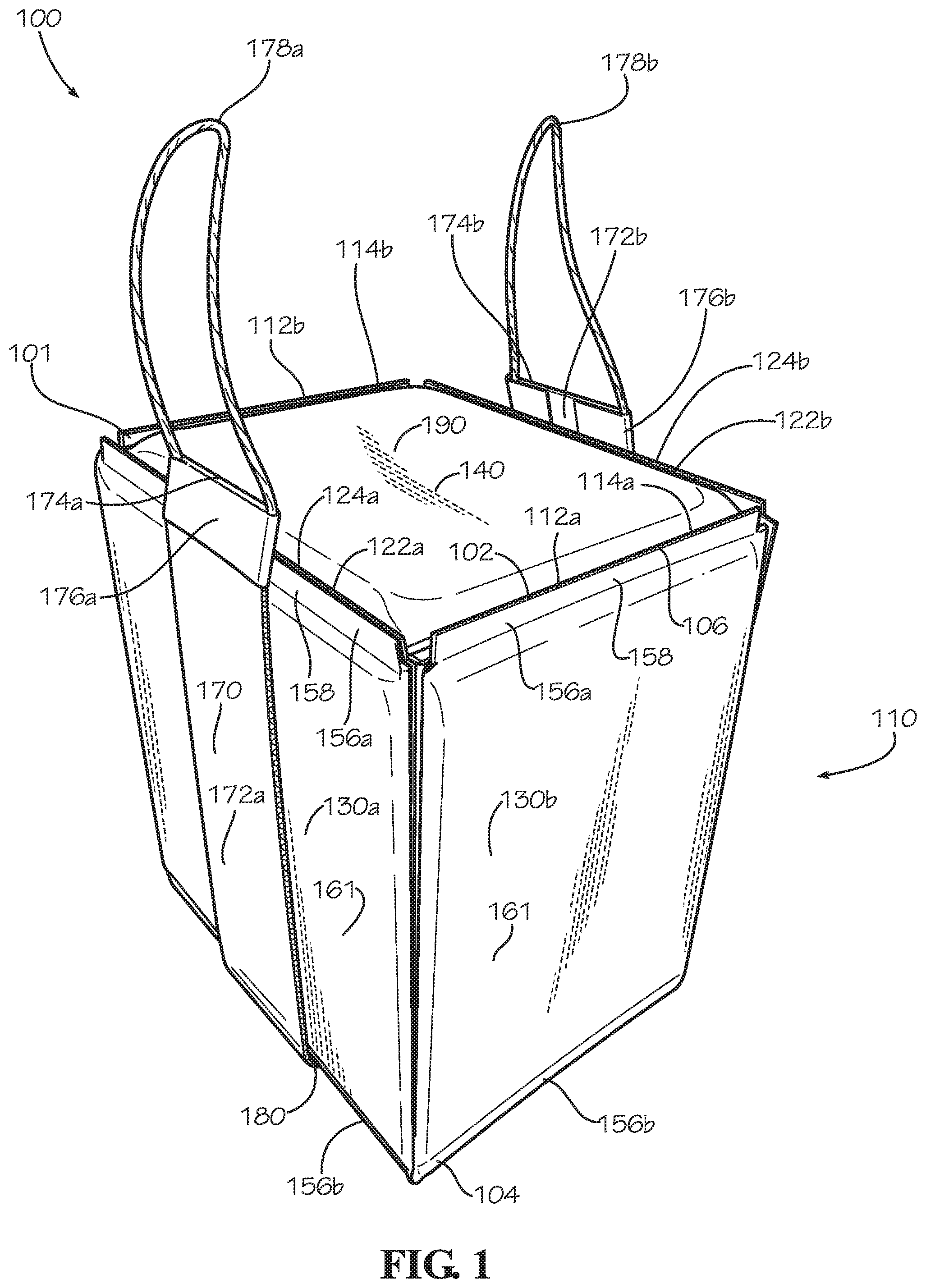
FIG. 1 is a perspective view of an insulated box assembly comprising an insulated box, a box top, and a carrying accessory in accordance with one aspect of the current disclosure.
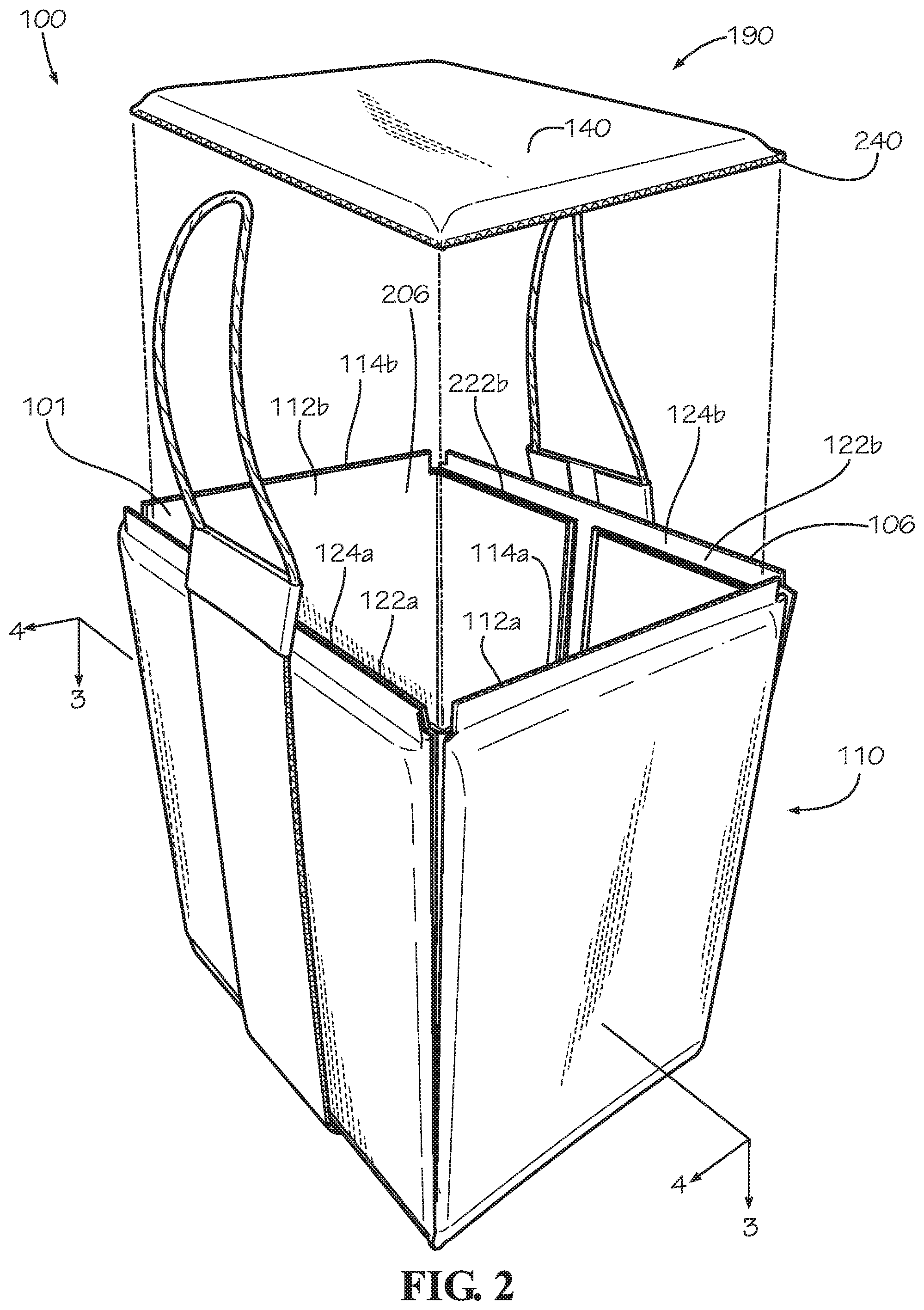
FIG. 2 is a perspective view of the insulated box assembly of FIG. 1 with the insulated box in an open position.
FIG. 3 is a cross-section of the insulated box of FIG. 1 taken along line 3-3 shown in FIG. 2.
FIG. 4 is a cross-section of the insulated box assembly of FIG. 1 taken along line 4-4 shown in FIG. 2.
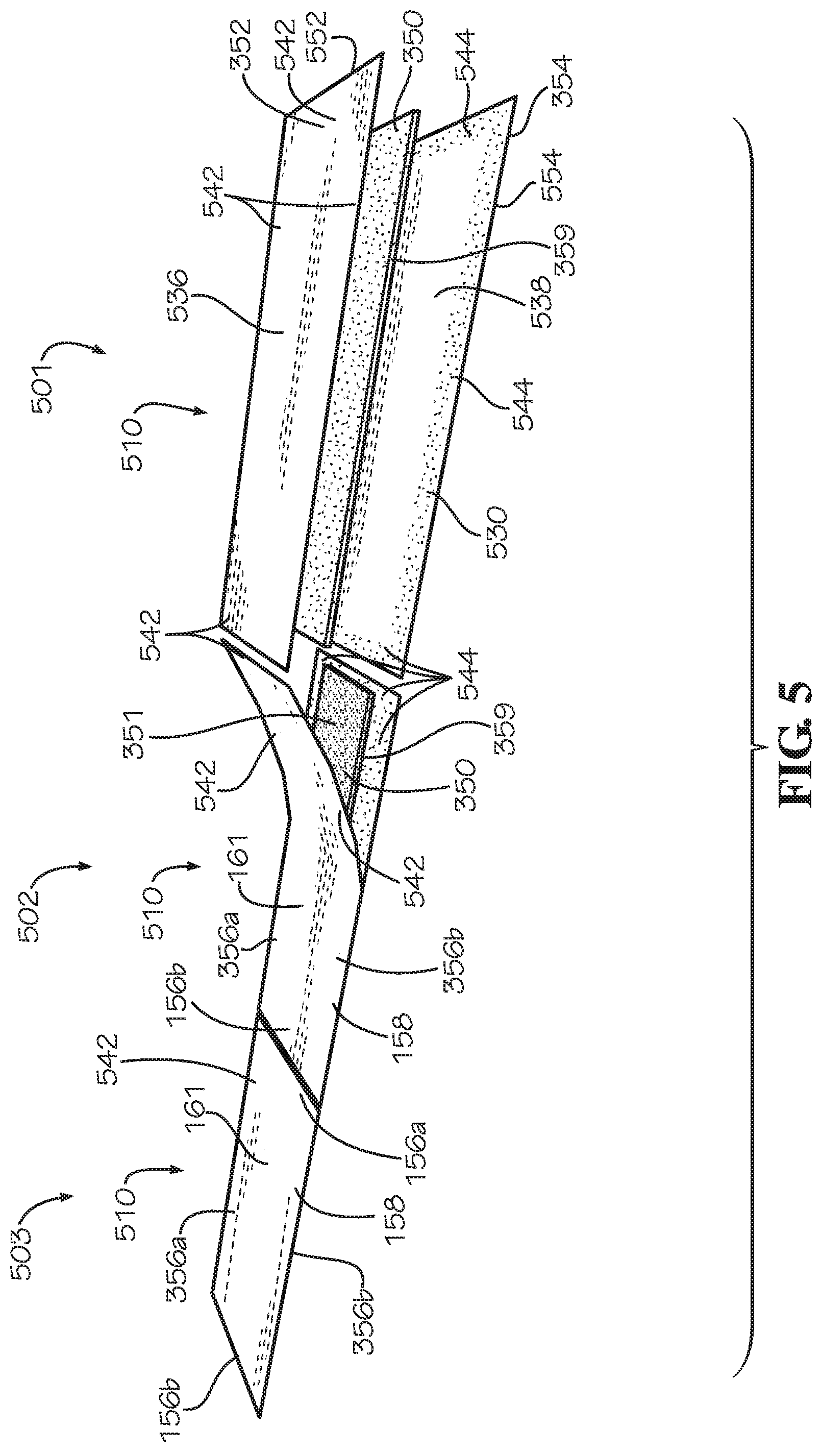
FIG. 5 is a perspective view of a method for manufacturing an insulated panel in accordance with another aspect of the current disclosure.
FIG. 6A is a perspective view of another aspect of an insulated panel in accordance with another aspect of the current disclosure prepared for installation on a box of the insulated box of FIG. 1.
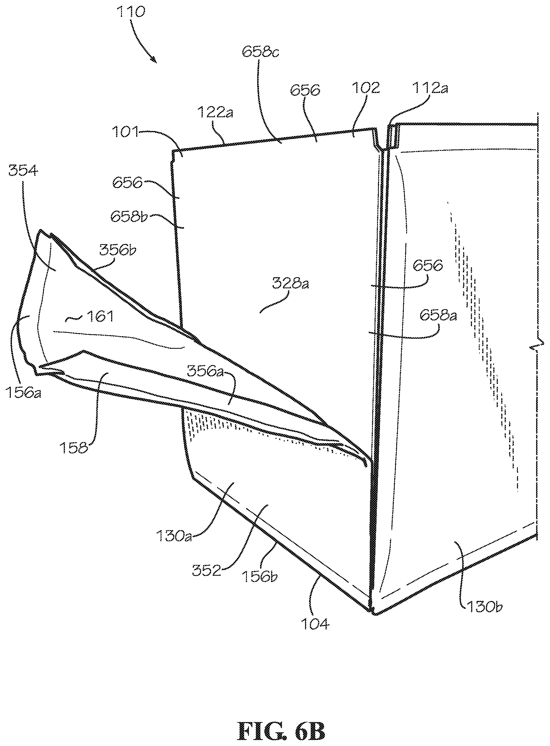
FIG. 6B is a perspective view of the insulated panel of FIG. 6A partially installed on the box of FIG. 6A.
FIG. 6C is a perspective view of the insulated panel of FIG. 6A completely installed on the insulated box of FIG. 6A.
FIG. 7 is a top view of a box blank of the box of FIG. 6A.
FIG. 8 is a perspective view of the insulated box of FIG. 1 in a collapsed configuration.
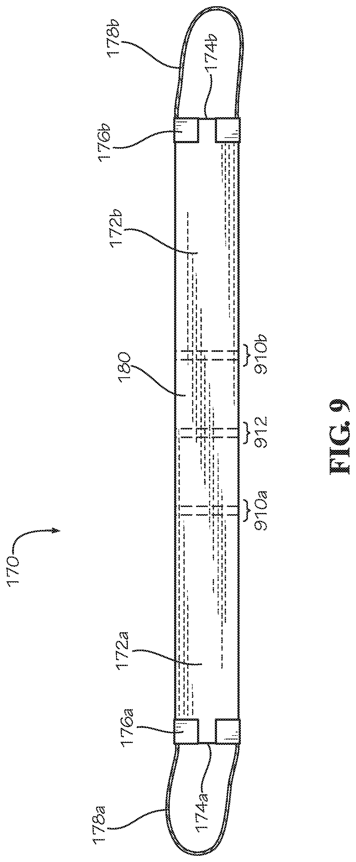
FIG. 9 is a top view of the carrying accessory of the insulated box assembly of FIG. 1.
FIG. 10 is a perspective view of the insulated box assembly comprising the insulated box of FIG. 1 and another aspect of a box top in accordance with another aspect of the present disclosure.
FIG. 11 is a perspective view of the insulated box assembly comprising the insulated box of FIG. 1 and another aspect of a box top in accordance with another aspect of the present disclosure.
FIG. 12 is a perspective view of the insulated box assembly comprising the insulated box of FIG. 1 and another aspect of a box top in accordance with another aspect of the present disclosure.
DETAILED DESCRIPTION
The present disclosure can be understood more readily by reference to the following detailed description, examples, drawings, and claims, and the previous and following description. However, before the present devices, systems, and/or methods are disclosed and described, it is to be understood that this disclosure is not limited to the specific devices, systems, and/or methods disclosed unless otherwise specified, and, as such, can, of course, vary. It is also to be understood that the terminology used herein is for the purpose of describing particular aspects only and is not intended to be limiting.
The following description is provided as an enabling teaching of the present devices, systems, and/or methods in its best, currently known aspect. To this end, those skilled in the relevant art will recognize and appreciate that many changes can be made to the various aspects of the present devices, systems, and/or methods described herein, while still obtaining the beneficial results of the present disclosure. It will also be apparent that some of the desired benefits of the present disclosure can be obtained by selecting some of the features of the present disclosure without utilizing other features. Accordingly, those who work in the art will recognize that many modifications and adaptations to the present disclosure are possible and can even be desirable in certain circumstances and are a part of the present disclosure. Thus, the following description is provided as illustrative of the principles of the present disclosure and not in limitation thereof.
As used throughout, the singular forms "a," "an" and "the" include plural referents unless the context clearly dictates otherwise. Thus, for example, reference to "an element" can include two or more such elements unless the context indicates otherwise.
Ranges can be expressed herein as from "about" one particular value, and/or to "about" another particular value. When such a range is expressed, another aspect includes from the one particular value and/or to the other particular value. Similarly, when values are expressed as approximations, by use of the antecedent "about," it will be understood that the particular value forms another aspect. It will be further understood that the endpoints of each of the ranges are significant both in relation to the other endpoint, and independently of the other endpoint.
For purposes of the current disclosure, a material property or dimension measuring about X or substantially X on a particular measurement scale measures within a range between X plus an industry-standard upper tolerance for the specified measurement and X minus an industry-standard lower tolerance for the specified measurement. Because tolerances can vary between different materials, processes and between different models, the tolerance for a particular measurement of a particular component can fall within a range of tolerances.
As used herein, the terms "optional" or "optionally" mean that the subsequently described event or circumstance can or cannot occur, and that the description includes instances where said event or circumstance occurs and instances where it does not.
The word "or" as used herein means any one member of a particular list and also includes any combination of members of that list. Further, one should note that conditional language, such as, among others, "can," "could," "might," or "may," unless specifically stated otherwise, or otherwise understood within the context as used, is generally intended to convey that certain aspects include, while other aspects do not include, certain features, elements and/or steps. Thus, such conditional language is not generally intended to imply that features, elements and/or steps are in any way required for one or more particular aspects or that one or more particular aspects necessarily include logic for deciding, with or without user input or prompting, whether these features, elements and/or steps are included or are to be performed in any particular aspect.
Disclosed are components that can be used to perform the disclosed methods and systems. These and other components are disclosed herein, and it is understood that when combinations, subsets, interactions, groups, etc. of these components are disclosed that while specific reference of each various individual and collective combinations and permutation of these may not be explicitly disclosed, each is specifically contemplated and described herein, for all methods and systems. This applies to all aspects of this application including, but not limited to, steps in disclosed methods. Thus, if there are a variety of additional steps that can be performed it is understood that each of these additional steps can be performed with any specific aspect or combination of aspects of the disclosed methods.
Disclosed is an insulated box assembly and associated methods, systems, devices, and various apparatus. The insulated box assembly comprises an insulated box, a box top, and a carrying accessory. It would be understood by one of skill in the art that the disclosed insulated box assembly is described in but a few exemplary embodiments among many. No particular terminology or description should be considered limiting on the disclosure or the scope of any claims issuing therefrom.
FIG. 1 is a perspective view of an insulated box assembly 100 in a closed position in accordance with one aspect of the present disclosure. The insulated box assembly 100 can comprise an insulated box 110, a carrying accessory 170, and a box top 190. The insulated box 110 can comprise a box 101 and a plurality of insulated panels 130a-d (insulated panels 130c,d shown in FIG. 3). The box 101 can comprise a rigid board material such as corrugated cardboard; however in other aspects, the box 101 can comprise other suitable rigid board materials, such as wood, plastic, metal, or any other material.
The box 101 can comprise a first pair of opposing side panels 112a,b and a second pair of opposing side panels 122a,b. The side panels 112a,b,122a,b can each be a rigid panel. The side panel 112a can be substantially parallel to the side panel 112b, and the side panel 122a can be substantially parallel to the side panel 122b. Each side panel 112a,b can be substantially perpendicular to both side panels 122a,b. The box 101 can define a rectangular or square cross-sectional shape; however, in other aspects, the box 101 can define a different cross-sectional shape such as a circular, triangular, pentagonal, or hexagonal, shape or any other desired shape.
The box 101 can define a top end 102 and a bottom end 104, and the top end 102 can be disposed opposite from the bottom end 104. The side panels 112a,b can define lips 114a,b, respectively, disposed proximate to the top end 102 of the insulated box 110. The side panels 122a,b can define lips 124a,b, respectively, disposed proximate to the top end 102 of the insulated box 110. The box 101 can define a box opening 106 at the top end 102. The box top 190 can be sized and shaped to fit between the lips 114a,b and the lips 124a,b to cover the box opening 106 when the insulated box 110 is in the closed position. The box top 190 can comprise an insulated panel 140 which can be substantially identical in construction to the insulated panels 130a-d; however in other aspects, the insulated panel 140 can differ in construction from the insulated panels 130a-d.
The insulated panels 130a-d can be attached to the side panels 112a,b,122a,b. The insulated panels 130a,c (130c shown in FIG. 3) can be respectively attached to the side panels 112a,b, and the insulated panels 130b,d (130d shown in FIG. 3) can be respectively attached to the side panels 122a,b. Each insulated panel 130a-d can define a border 158 extending around the respective insulated panel 130a-d. An area encircled by the border 158 can define an insulated portion 161 of the respective insulated panel 130.
The border 158 of each insulated panel 130a-d can define a top seam 156a and a bottom seam 156b extending outwards from the insulated portion 161 of the respective insulated panel 130a-d. The top seam 156a can be attached to the adjacent side panel 112a,b,122a,b of the box 101 proximate the top end 102 of the box 101. In the present aspect, the top seam 156a of each insulated panel 130a-d can attach to the lip 114a,b,124a,b of the adjacent side panel 112a,b,122a,b. The bottom seam 156b of each insulated panel 130a-d can be attached to the adjacent side panel 112a,b,122a,b along the bottom end 104 of the box 101. The seams 156a,b can be attached by an adhesive such as a glue, cement, epoxy, mastic, double-sided tape, cohesive, or any other suitable material, and the seams 156a,b can secure the insulated panels 130a-d to the respective adjacent side panels 112a,b,122a,b.
The carrying accessory 170 can extend beneath the insulated box 110 to facilitate hand carrying of the insulated box 110. The carrying accessory 170 can define a U-shape. A middle portion 180 can extend beneath the insulated box 110. A first side portion 172a can extend upwards from the middle portion 180 and can be adjacent to the insulated panel 130a. A second side portion 172b can extend upwards from the middle portion 180 and can be adjacent to the insulated panel 130c (shown in FIG. 3).
In the present aspect, the carrying accessory 170 can be attached to the insulated box 110 such as with an adhesive, such as a glue, cement, epoxy, mastic, double-sided tape, cohesive, or any other suitable material. In other aspects, the carrying accessory 170 can be mechanically attached, such as with a hook-and-loop fastener, stitching, or staples, and the mechanical attachment of the carrying accessory 170 can be configured to be selectively attached and detached from the insulated box 110 such as with hook-and-loop fasteners. In other aspects, the carrying accessory 170 may not be attached to the insulated box 110. In some aspects, the side portions 172a,b can extend upwards adjacent to the insulated panels 130b,d. In some aspects, the carrying accessory 170 can have four side portions (not shown), and one side portion can be positioned adjacent to each of the four insulated panels 130a-d.
The side portions 172a,b can respectively define handles 178a,b. In the present aspect, handle 178a can be attached to an end 174a of the first side portion 172a by a base strip 176a. Handle 178b can be attached to an end 174b of the second side portion 172b by a base strip 176b. The handles 178a,b can comprise twisted paper rope, and the handles 178a,b can be laminated between two layers of the respective base strip 176a,b. In other aspects, the handles 178a,b can be integrally formed with the base strips 176a,b, and the handles 178a,b and the base strips 176a,b can comprise a common material. For example, the base strips 176a,b and the handles 178a,b can comprise a heavy kraft paper, plastic, posterboard, cardboard, or other suitable material. In other aspects, the handles 178a,b can comprise a fiber such as cotton, hemp, jute, or bamboo fiber.
The base strips 176a,b can be attached to the respective ends 174a,b with an adhesive such as a glue, cement, epoxy, mastic, double-sided tape, cohesive, or any other suitable material. The ends 174a,b and the handles 178a,b can extend upwards above the box opening 106. In other aspects, the handles 178a,b and the ends 174a,b may not extend above the box opening 106, and the handles 178a,b can be positioned adjacent to the insulated panels 130b,d. In other aspects, the handles 178a,b can have a different shape and can be attached directly to the respective side portions 172a,b. In some aspects, the handles 178a,b can be formed integrally with the respective side portions 172a,b, for example, by cutting a hand hole through the respective side portion 172a,b.
FIG. 2 is a perspective view of the insulated box assembly 100 of FIG. 1 with the box top 190 in an open position. In the open position, the box top 190 can be removed from the box opening 106, thereby exposing a box cavity 206 defined within the box 101. The first pair of opposing side panels 112a,b and the second pair of opposing side panels 122a,b of the box 101 can define the box cavity 206. A pair of shoulders 222a,b can extend inwards into the box cavity 206 from each of the side panels 122a,b, as represented by the shoulder 222b (shoulder 222a shown in FIG. 3). The shoulders 222a,b are configured to support the box top 190 when the box top 190 is positioned between the lips 114a,b,124a,b in the closed position. In the closed position, the box top 190 can cover the box opening 106 and enclose the box cavity 206.
In the present, aspect, the box top 190 can comprise the insulated panel 140 and a top panel 240. The top panel 240 can be a rigid panel. The insulated panel 140 can be attached to the top panel 240 and positioned atop the top panel 240 as shown. In other aspects, the box top 190 can be flipped, and the insulated panel 140 can be positioned beneath the top panel 240. In other aspects, the box top 190 can comprise a second insulated panel (not shown), and the box top 190 can be insulated on both sides for added insulation value. In other aspects, the box top 190 may not comprise the insulated panel 140, and the top panel 240 can be uninsulated. The top panel 240 can comprise corrugated cardboard in the present aspect; however, in other aspects the top panel 240 can be comprise a suitable rigid board material such as wood, plastic, metal, or any other material.
FIG. 3 is a cross-section of the insulated box 110 of FIG. 1 taken along line 3-3 shown in FIG. 2, with the carrying accessory 170 and the box top 190 removed. As shown, each shoulder 222a,b can comprise two sub-shoulders 322. The shoulder 222a can comprise the sub-shoulders 322a,b, and the shoulder 222b can comprise the sub-shoulders 322c,d. The sub-shoulders 322a-d can be defined by a plurality of first wings 312a-d and a plurality of second wings 324a-d. The first wings 312a,b can be attached at opposite sides of the side panel 112a, and the first wings 312c,d can be attached at opposite sides of the side panel 112b. The second wings 324a,b can be attached at opposite sides of the side panel 122a, and the second wings 324c,d can be attached at opposite sides of the side panel 122b.
The second wing 324a can be folded inwards at a hinge 365a and positioned adjacent to an inner side surface 326a defined by the side panel 122a, and the first wing 312c can be folded at a hinge 370c and positioned adjacent to the second wing 324a. The second wing 324a and the first wing 312c can be secured in position, such as with an adhesive, to form the sub-shoulder 322a. The second wing 324b can be folded inwards at a hinge 365b and positioned adjacent to the inner side surface 326a, and the first wing 312a can be folded at a hinge 370a and positioned adjacent to the second wing 324b. The second wing 324b and the first wing 312a can be secured in position, such as with an adhesive, to form the sub-shoulder 322b.
For the sub-shoulder 322c of shoulder 222b, the second wing 324c can be folded inward at a hinge 365c and positioned adjacent to an inner side surface 326b defined by the side panel 122b. The first wing 312d can then be folded at a hinge 370d and positioned adjacent to the second wing 324c. The first wing 312d and the second wing 324c can be secured in position, such as with an adhesive, to form the sub-shoulder 322c. For the sub-shoulder 322d of shoulder 222b, the second wing 324d can be folded inward at a hinge 365d and positioned adjacent to the inner side surface 326b. The first wing 312b can then be folded at a hinge 370b and positioned adjacent to the second wing 324d. The first wing 312b and the second wing 324d can be secured in position, such as with an adhesive, to form the sub-shoulder 322d.
The formation of the sub-shoulders 322a-d can also secure each side panel 112a,b to each side panel 122a,b, thereby defining the square or rectangular horizontal cross-section of the box 101. The box 101 can further comprise a bottom panel 306. The bottom panel 306 can be a rigid panel. The bottom panel 306 can be disposed at the bottom end 104 of the box 101, and the bottom panel 306 can be attached to each of the side panels 112a,b,122a,b. The bottom panel 306 can further define the box cavity 206. The box 101 is but one example of a box, and the methods discussed below for insulating the box 101 to form the insulated box 110 can be applied to a box of another shape, size, or form.
In the present aspect, the bottom panel 306 can define a center subpanel 380 disposed at a center of the bottom panel 306. The center subpanel 380 can be substantially rectangular in shape. A center fold line 382 can extend between the center subpanel 380 and each side panel 112a,b, and the center fold line 382 can substantially bisect the bottom panel 306, with the exception of within the center subpanel 380. The center fold line 382 can also bisect each side panel 112a,b, as shown and further described with respect to FIG. 7. Four corner fold lines 384a-d can extend between the corners of the center subpanel 380 and the hinges 370a-d. The corner fold line 384a can extend from the hinge 370a to the center subpanel 380. The corner fold line 384b can extend from the hinge 370b to the center subpanel 380. The corner fold line 384c can extend from the hinge 370c to the center subpanel 380. The corner fold line 384d can extend from the hinge 370d to the center subpanel 380.
A plurality of V-shaped fold lines 386a-f can extend between the hinges 370a-d and the center fold line 382. The V-shaped fold lines 386a-c can each extend from the hinge 370a to center fold line 382 and then to the hinge 370b. The V-shaped fold lines 386a-c can be defined between the corner fold lines 384a and 384b. The V-shaped fold lines 386d-f can each extend from the hinge 370c to center fold line 382 and then to the hinge 370d. The V-shaped fold lines 386d-f can be defined between the corner fold lines 384c and 384d. The center subpanel 380, the center fold line 382, the corner fold lines 384a-d, and the V-shaped fold lines 386a-f can cooperate to collapse the insulated box 110 and to provide the bottom panel 306 with a truncated pyramidal shape when collapsed, as further discussed below with respect to FIG. 8.
The box 101 of the insulated box 110 can be clad with the insulated panels 130a-d. The insulated panel 130a can be attached to an outer side surface 328a defined by the side panel 122a. The insulated panel 130b can be attached to an outer side surface 314a defined by the side panel 112a. The insulated panel 130c can be attached to an outer side surface 328b defined by the side panel 122b. The insulated panel 130d can be attached to an outer side surface 314b defined by the side panel 112b. In the present aspect, the box 101 can be externally clad with the insulated panels 130a-d, however in other aspects, the box 101 can be internally clad, both internally and externally clad, or a mixed arrangement of partially internally clad and partially externally clad with insulated panels 130.
In the present aspect, each insulated panel 130a-d can comprise an insulation batt 350, a first sheet 352, and a second sheet 354. The insulation batt 350 can be encapsulated in a panel cavity 351 defined between the first sheet 352 and the second sheet 354. The insulation batt 350 can be encapsulated by the border 158 which can extend around a perimeter 359 of the insulation batt 350, thereby sealing the panel cavity 351. The panel cavity 351 containing the insulation batt 350 can define the insulated portion 161 of the respective insulated panel 130a-d. The border 158 can be a seam formed by attaching a perimeter portion of the first sheet 352 which overhangs the perimeter 359 of the insulation batt 350 with a perimeter portion of the second sheet 354 which also overhangs the perimeter 359 of the insulation batt 350. The first sheet 352 can be attached to the second sheet 354 with an adhesive such as a glue, cement, epoxy, mastic, cohesive, double-side tape or other suitable adhesive to form the border 158. In some aspects, the border 158 can be formed by mechanically fastening the first sheet 352 to the second sheet 354, such as by stapling, stitching, or any other suitable method of fastening.
The border 158 can further define a first side seam 356a and a second side seam 356b. In the present aspect, the first side seam 356a and the second side seam 356b can be vertically oriented seams. The first side seam 356a and the second side seam 356b of the border 158 can be folded inwards and disposed between the insulation batt 350 of the insulated portion 161 and the outer side surface 328a,b of the respective side panels 122a,b or the outer side surfaces 314a,b of the respective side panels 112a,b. The first side seam 356a and the second side seam 356b can be attached to the adjacent side panel 112a,b,122a,b, thereby further securing the insulated panel 130a-d to the adjacent side panel 112a,b,122a,b and enclosing the insulation batt 350 between the first sheet 352 and the adjacent side panel 112a,b,122a,b. By folding the first side seam 356a and the second side seam 356b inwards, the insulation batt 350 and the insulated portion 161 can extend completely across or nearly completely across the width of the adjacent side panel 112a,b,122a,b without leaving the first side seam 356a and the second side seam 356b sticking outwards beyond the side panel 112a,b,122a,b. This configuration can provide full insulation or nearly full insulation over the width of the adjacent side panel 112a,b,122a,b.
With the first side seam 356a and the second side seam 356b folded inwards, the first sheet 352 can be attached to the respective adjacent side panel 112a,b,122a,b with an adhesive such as a glue, cement, epoxy, mastic, double-sided tape, cohesive, or other suitable material. A portion of the second sheet 354 extending between the first side seam 356a and the second side seam 356b can also be in facing contact with the adjacent side panel 112a,b,122a,b and can optionally be attached with the adhesive. In other aspects, the insulated panels 130a-d may not comprise the second sheet 354, and either the insulation batt 350 can be in facing contact with the respective adjacent side panel 112a,b,122a,b, or the first sheet 352 can fully encapsulate the insulation batt 350.
FIG. 4 is a cross-section of the insulated box assembly 100 of FIG. 1 taken along line 4-4 shown in FIG. 2. In the present view, the carrying accessory 170 has been removed. The insulated box assembly 100 can further comprise an insulated cavity panel 430 which can be disposed within the box cavity 206. The insulated cavity panel 430 can be constructed similar to the insulated panels 130a-d,190; however, in the present aspect, the insulated cavity panel 430 can be a loose panel. The insulated portion 161 of the insulated cavity panel 430 can be shaped and sized complimentary to the horizontal cross-section of the box 101 in order to provide a close fit within the box cavity 206.
As shown, the insulated cavity panel 430 can divide the box cavity 206 into a first sub-compartment 406a and a second sub-compartment 406b. In the present aspect, the insulated cavity panel 430 can be horizontally oriented, and the first sub-compartment 406a can be an upper sub-compartment while the second sub-compartment 406b can be a lower sub-compartment. In other aspects, the insulated cavity panel 430 can be vertically oriented to divide the box cavity 206 into side-by-side compartments. In some aspects, the insulated box 110 can comprise multiple cavity panels 430 disposed within the box cavity 206 to divide the box cavity 206 into more than two compartments or no cavity panels 430 so that the box cavity 206 is a single compartment. Dividing the box cavity 206 into sub-compartments can be desirable in order to package both hot and cold contents in the same insulated box 110 or other contents that should be stored at different temperatures.
In the present aspect, the bottom panel 306 can be uninsulated. Optionally, the insulated cavity panel 430 can be placed atop the bottom panel 306 to provide insulation for the bottom end 104 of the insulated box 110. In other aspects, the insulated box 110 can further comprise another insulated panel 130 (not shown) attached internally or externally to the bottom panel 306. In aspects in which the box top 190 can be uninsulated, the insulated cavity panel 430 can be positioned adjacent to the box top 190 to provide insulation for the top end 102 of the insulated box 110. In some aspects, the bottom panel 306 can be insulated and the insulated cavity panel 430 can be placed atop the bottom panel 306 in order to provide additional insulation for example. In some aspects, the insulated box assembly 100 can comprise multiple insulated cavity panels 430 positioned within the box cavity 206.
The bottom seam 156b and the top seam 156a of the border 158 of each insulated panel 130a-d can extend outwards from the perimeter 359 of the insulation batt 350 and the insulated portion 161. As previously discussed, the bottom seams 156b and the top seams 156a can be attached to the respective adjacent side panel 112a,b,122a,b with the adhesive in order to secure the insulated panels 130a-d, to the box 101 proximate the top end 102 and the bottom end 104. In such aspects, the second sheet 354 can be attached to the adjacent side panel 112a,b,122a,b, and the first sheet 352 may not contact the adjacent side panel 112a,b,122a,b at the bottom seam 156b and the top seam 156a; however, the insulation batt 350 remains enclosed between the first sheet 352 and the adjacent side panel 112a,b,122a,b. Optionally, portions of the second sheet 354 disposed between the top seams 156a and the bottom seam 156b can also be attached to the respective adjacent side panel 112a,b,122a,b with the adhesive.
The outward extending top seams 156a can leave the lips 114a,b,124a,b uninsulated; however, because the box top 190 rests below the box opening 106 on the shoulders 222a,b (should 222b shown in FIG. 3), the top end 102 of the insulated box 110 can remain fully insulated. Similarly, the bottom seams 156b can leave a portion of the side panels 112a,b,122a,b proximate the bottom panel 306 uninsulated. However, in aspects in which the insulated cavity panel 430 can be positioned atop the bottom panel 306, the insulated cavity panel 430 can fully insulate the bottom end 104 of the insulated box 110. In other aspects, either or both of the bottom seams 156b and top seams 156a can be folded inward towards the insulation batt 350 and the insulated portion 161, and the insulation batt 350 can fully cover the height of the side panels 112a,b,122a,b.
The outwardly extended bottom seams 156b can define a bottom taper 458 extending around the insulated box 110 proximate the bottom end 104. The bottom taper 458 can cooperate with the lips 114a,b,124a,b to securely stack multiple insulated boxes 110 on top of one another. The lips 114a,b,124a,b of a lower insulated box of the stack of insulated boxes can deflect outwards allowing the bottom taper 458 of an upper insulated box to nest between the lips 114a,b,124a,b and atop the box top 190 of the lower insulated box. By nesting between the lips 114a,b,124a,b, the lips 114a,b,124a,b can prevent the upper insulated box from sliding sideways off the top end 102 of the lower insulated box. The insulated boxes 110 can also be conveyable, such as on a conveyor belt, and the insulated boxes 110 can be rigid and strong enough to resist collapse on the conveyor belt.
FIG. 5 is a perspective view of a method of manufacturing for an insulated panel 510. The method can apply to the manufacture of the insulated panels 130a-d,140,430. In a step 501, the insulation batt 350 can be positioned between the first sheet 352 and the second sheet 354. The first sheet 352 and the second sheet 354 can be sized and shaped complimentary to each other; however in some aspects, the sheets 352,354 can differ in size and shape. The insulation batt 350 and the sheets 352,354 can each be flat and substantially planar before assembly. In the present aspect, the insulation batt 350 can be approximately 3/8'' thick; however this thickness is not limiting. The thickness can range from 1/16'' to over 2'' with a preferred range of 1/4'' to 1/2''.
The first sheet 352 can define a first outer edge 552, and a portion of the first sheet 352 proximate the first outer edge 552 can define a first perimeter portion 542. The second sheet 354 can define a second outer edge 554, and a portion of the second sheet 354 proximate the second outer edge 554 can define a second perimeter portion 544. The sheets 352,354 can be sized to overhang the insulation batt 350 on all sides with the first perimeter portion 542 and the second perimeter portion 544 extending beyond the perimeter 359 of the insulation batt 350. The first perimeter portion 542 can encompass a first interior portion 536 of the first sheet 352, and the second perimeter portion 544 can encompass a second interior portion 538 of the second sheet 354. The interior portions 536,538 can be sized and shaped complimentary to the insulation batt 350.
Surfaces of the sheets 352,354 facing one another can be treated with an adhesive 530 such as a cohesive. In various aspects, the adhesive can be a glue, epoxy, cement, double-sided tape, or other suitable adhesive. The surfaces can be entirely treated with the adhesive 530 or selectively treated with the adhesive 530. In the aspect shown, the perimeter portions 542,544 can be selectively treated with the adhesive 530. In some aspects, the insulation batt 350 can also be adhered to the interior portions 536,538 of the sheets 352,354.
In a step 502, the sheets 352,354 can be aligned and positioned in facing engagement wherein the first perimeter portion 542 can be attached to the second perimeter portion 544 by the adhesive 530. The insulation batt 350 can be aligned between the interior portions 536,538. Attaching the perimeter portions 542,544 can form the border 158 of the insulated panel 510 around the perimeter 359 of the insulation batt 350. As depicted in step 502, the bottom seam 156b has been formed, the first side seam 356a and the second side seam 356b are partially formed, and the top seam 156a is yet to be formed.
The border 158 can seal the insulation batt 350 within the panel cavity 351 defined between the interior portions 536,538 of the sheets 352,354, respectively. Portions of the insulated panel 510 containing the insulation batt 350 can define the insulated portion 161 of the insulated panel 510. In some aspects, the insulation batt 350 can be aligned off-center from the sheets 352,354 wherein the border 158 can extend outwards further in some areas than others. In some aspects, the first side seam 356a, the second side seam 356b, the bottom seam 156b, and the top seam 156a can define different widths from one another. For example and without limitation, the first side seam 356a can extend outwards from the insulation batt 350 further than the bottom seam 156b or vice versa.
In a step 503, the first perimeter portion 542 has been fully attached to the second perimeter portion 544, thereby forming the completed border 158. Each of the first side seam 356a, the second side seam 356b, the bottom seam 156b, and the top seam 156a are fully formed. Manufacturing of the insulated panel 510 is thus completed; however in some aspects, the method can comprise additional steps such as cutting slots into the border 158. The border 158 can fully encapsulate the insulation batt 350 within the panel cavity 351; however in some aspects, the insulation batt 350 may not be fully encapsulated. In some aspects, the insulation batt 350 can define a complex shape which can comprise curves, notches, cutouts, or other features which can be reflected by complimentary shapes of the border 158 and the insulated portion 161.
In other aspects, the border 158 may not fully encompass and encapsulate the insulation batt 350. In some aspects, some portions of the perimeter 359 may be exposed at an unfinished side or a cutout of the border 158. In some aspects, the insulated panel 510 may not define the border 158 on any portion of the perimeter of the insulated panel 510, and the entire perimeter can define an unfinished edge. In such aspects, the insulated panel 510 can comprise pre-laminated paper and each of the sheets 352,354 can be attached in facing contact with the insulation batt 350 with, for example and without limitation, an adhesive. In some aspects in which the insulated panel 510 defines the border 158, the insulation batt 350 can also be attached in facing contact with one or both of the sheets 352,354. In some aspects, the pre-laminated paper can be provided in a roll, and the insulated panels 510 can be cut to size from the roll. In other aspects, the first sheet 352 and the second sheet 354 can be halves of a single sheet (not shown) which can be folded substantially in half. In such aspects, the insulation batt 350 can be encapsulated between the two halves of the single sheet. In other aspects, the second sheet 354 can be a board (not shown), such as a piece of cardboard, and the insulation batt 350 can be encapsulated between the first sheet 352 and the board.
FIGS. 6A-C show perspective views of a method for attaching the insulated panel 130a to the side panel 122a. In FIG. 6A, the insulated panel 130a is shown partially attached to the side panel 122a. In the present aspect, the insulated panel 130a and the adjacent insulated panel 130b can be separate and isolated insulation panels 130 which are not connected together. By using isolated insulated panels 130, manufacturing stress around corners of the insulated box 110 can be reduced during assembly of the insulated box 110, thereby reducing the likelihood of ripping or tearing the insulated panels 130 during assembly. The insulated panel 130a can be positioned adjacent to the side panel 122a, and the bottom seam 156b can be attached to a perimeter area 656 of the outer side surface 328a. The perimeter area 656 can extend around the edges of the side panel 122a. Specifically, the bottom seam 156b can be attached to a bottom portion (not shown) of the perimeter area 656 extending along the bottom end 104 of the side panel 122a. The perimeter area 656 can also define a first portion 658a and a second portion 658b extending upwards from the bottom portion towards a top portion 658c. The top portion 658c can extend along the lip 124a proximate the top end 102 of the side panel 122a.
The bottom seam 156b of the border 158 can extend outwards from the insulated portion 161 of the insulated panel 130a, and the second sheet 354 of the bottom seam 156b can be attached to the outer side surface 328a. In other aspects, the bottom seam 156b can be folded inwards towards the insulation batt 350 (not shown) encapsulated within the insulated portion 161. The bottom seam 156b can be attached in facing contact with the side panel 122a by an adhesive such as a glue, epoxy, cement, mastic, or any other suitable adhesive. In other aspects, the bottom seam 156b can be mechanically attached to the side panel 122a such as with a hook-and-loop fastener, stitching, or staples, or other suitable fasteners. In the present aspect, the first side seam 356a and the second side seam 356b (shown in FIG. 6B) can be folded inwards towards the insulation batt 350 (not shown) encapsulated within the insulated portion 161. The first side seam 356a can be attached to the bottom portion (not shown) at an intersection between the bottom portion and the first portion 658a of the perimeter area 656. The second side seam 356b can be attached to the bottom portion (not shown) at an intersection between the bottom portion and the second portion 658b of the perimeter area 656.
In FIG. 6B, the insulated panel 130a is shown with the bottom seam 156b attached to the side panel 122a, and the first side seam 356a and the second side seam 356b partially attached to the first portion 658a and the second portion 658b of the perimeter area 656, respectively. The first sheet 352 of the first side seam 356a and the second side seam 356b can be attached in facing contact to the perimeter portion 656 of the outer side surface 328a by an adhesive such as a glue, epoxy, cement, mastic, double-sided tape, cohesive, or other suitable adhesive. In other aspects, the first sheet 352 of the first side seam 356a and the second side seam 356b can be mechanically attached to the perimeter portion 656 of the outer side surface 328a, such as with a hook-and-loop fastener, stitching, or staples, or other suitable fasteners. In the aspect shown, the insulated panel 130a is shown as first attached proximate the bottom end 104 and then subsequently attached upwards along the first side seam 356a and the second side seam 356b towards the top end 102; however, this sequence and direction of attachment are not limiting. The insulated panel 130a can first be attached at the first side seam 356a, the second side seam 356b, or the top seam 156a and further attached in a sideways or downwards direction, or in any other suitable sequence. In some aspects, the second sheet 354 of the insulated portion 161 can also be attached to the outer side surface 328a by an adhesive such as a glue, epoxy, cement, mastic, or any other suitable adhesive.
FIG. 6C shows the insulated panel 130a completely attached to the side panel 122a. The first side seam 356a (shown in FIG. 6B) can be completely attached to the first portion 658a (shown in FIG. 6B) of the perimeter area 656 (shown in FIG. 6B) from the bottom end 104 to the top end 102. The second side seam 356b (shown in FIG. 6B) can be completely attached to the second portion 658b (shown in FIG. 6B) of the perimeter area 656 (shown in FIG. 6B) from the bottom end 104 to the top end 102. The top seam 156a can be fully attached to the top portion 658c (shown in FIG. 6B) by an adhesive such as a glue, epoxy, cement, mastic, double-sided tape, cohesive, or any other suitable adhesive. In other aspects, the top seam 156a can be mechanically attached to the top portion 658c, such as with a hook-and-loop fastener, staples, or stitching, or other suitable fasteners.
The method for attaching the insulated panel 130a to the side panel 122a shown in FIGS. 6A-C can apply to any of the insulated panels 130a-d,140 and any of the adjacent panels 112a,b,122a,b,240. The method can also be used to attach the insulated panels 130a-d to an inner surface, such as inner side surfaces 326a,b, within the box cavity 206. The method is demonstrated on the assembled box 101, and the method is exemplary and not limiting. The various panels 112a,b,122a,b,306 of the box 101 can be clad with insulated panels 130a-d prior to assembly of the box 101. For example, the insulated panels 130a-d, can be attached to the respective panels 112a,b,122a,b of an unfolded box blank 710 (shown in FIG. 7). It can be desirable to attach the insulated panels 130a-d to the unfolded box blank 710 prior to assembly in order to reduce mechanical handling of the box 101.
FIG. 7 is a top view of the box blank 710 which can be assembled to form the box 101 of the insulated box 110. The box blank 710 can further define four corner cuts 750a-d. In other aspects, the box blank 710 can define fold lines or scored lines in place of the corner cuts 750a-d. A first corner cut 750a can extend outwards from the bottom panel 306 to separate the first wing 312a from the second wing 324b. A second corner cut 750b can extend outwards from the bottom panel 306 to separate the first wing 312b from the second wing 324d. A third corner cut 750c can extend outwards from the bottom panel 306 to separate the first wing 312c from the second wing 324a. A fourth corner cut 750d can extend outwards from the bottom panel 306 to separate the first wing 312d from the second wing 324c. In other aspects, the corner cuts 750a-d can be creases instead of cuts, and the adjacent wings 312a-d,324a-d can be hingedly connected by the corner cuts 750a-d.
The box blank 710 can define a first length fold line 712a and a second length fold line 712b extending from the side panel 112a to the side panel 112b. The first length fold line 712a can facilitate folding of the first wing 312a relative to the side panel 112a, the side panel 122a relative to the bottom panel 306, and the first wing 312c relative to the second side panel 112b. The second length fold line 712b can facilitate folding of the first wing 312b relative to the side panel 112a, the side panel 122b relative to the bottom panel 306, and the first wing 312d relative to the side panel 112b.
The box blank 710 can further define a first width fold line 722a and a second width fold line 722b. The width fold lines 722a,b can be defined substantially perpendicular to the length fold lines 712a,b. The first width fold line 722a can facilitate folding of the second wing 324a relative to the side panel 122a, the side panel 112b relative to the bottom panel 306, and the second wing 324c relative to the side panel 122b. The second width fold line 722b can facilitate folding of the second wing 324b relative to the side panel 122a, the side panel 112a relative to the bottom panel 306, and the second wing 324d relative to the side panel 122b.
The center fold line 382 can extend across and bisect each side panel 112a,b. The center fold line 382 facilitates each of the side panels 112a,b folding inwards about the center fold line 382 and towards the bottom panel 306 to facilitate collapsing the insulated box 110 as shown in FIG. 8.
In some aspects, the insulated panels 130a-d can be attached to the side panels 112a,b,122a,b to the unfolded box blank 710 prior to assembly. In other aspects, a single insulated panel 130a,b can be attached to the unfolded box blank 710 to cover the side panels 112a,b,122a,b, and in some aspects, the bottom panel 306 as well. In some aspects, the entire unfolded box blank 710 can be covered by a single insulated panel.
FIG. 8 is a perspective view of the insulated box 110 of FIG. 1 in a collapsed configuration. In the present view, the carrying accessory 170 is removed to better show the details of the bottom panel 306. As the insulated box 110 collapses, the side panels 122a,b (side panels 122a,b shown in FIG. 1) move inwards together and towards one another, and the side panels 112a,b fold inwards towards one another (side panels 112a,b shown in FIG. 1). The V-shaped fold lines 386a-f (V-shaped fold lines 386e,f shown in FIG. 7) cooperate to transition the bottom panel 306 from a substantially planar shape to the truncated pyramidal shape. In the truncated pyramidal shape, the center subpanel 380 extends outwards and away from the side panels 112a,b and the side panels 122a,b (shown in FIG. 7). Exerting a force upon the center subpanel 380, such as by pushing the box 101 against the ground can cause the insulated box 110 to self-expand into an expanded configuration (shown in FIG. 1) with a substantially rectangular prism shape. The self-expanding action can be desirable to allow for quick and easy reconfiguration of the insulated box 110, unlike many boxes which must be folded and taped together. The insulated boxes 110 can be shipped and stored in the collapsed configuration for space-efficient packing, and a user can simply press upon the center subpanel 380, such as by pressing the center subpanel 380 against the ground, and the insulated box 110 can reconfigure to the expanded configuration.
FIG. 9 is a top view of the carrying accessory 170 of FIG. 1. As previously described, the carrying accessory 170 can be configured to extend beneath the insulated box 110 (shown in FIG. 1) to facilitate hand carrying of the insulated box 110. The carrying accessory 170 can define two pairs of fold lines 910a,b. A first pair of fold lines 910a can be defined between the first side portion 172a and the middle portion 180, and a second pair of fold lines 910b can be defined between the second side portion 172b and the middle portion 180. The fold lines of each pair of fold lines 910a,b can be placed closely together, such as an inch apart or less, and can be substantially parallel to one another. The pairs of fold lines 910a,b configure the carrying accessory 170 to closely conform to the bottom taper 458 (shown in FIG. 3) of the bottom end 104 of the insulated box 110. The middle portion 180 of the carrying accessory 170 can also define a pair of middle fold lines 912. The middle fold lines 912 can configure the carrying accessory 170 to closely conform to the truncated pyramidal shape of the bottom panel 306 (shown in FIG. 8) when the insulated box 110 is in the collapsed configuration as shown in FIG. 8. In other aspects each or any of the pairs of fold lines 910a,b and 912 can be substituted with single fold lines as desired.
FIG. 10 is a perspective view of the insulated box assembly 100 comprising the insulated box 110 of FIG. 1 and another aspect of a box top 190 in accordance with another aspect of the present disclosure. In the present aspect, the box top 190 can be a tray top 1090. The tray top 1090 can comprise a top panel 1092 and four side panels, as represented by side panels 1094a,b, extending down from the top panel 1092. The tray top 1090 can be configured to fit over the top end 102 of the box 101 (shown in FIG. 1). The side panels 1094 can fit over the lips 114a,b,124a,b (shown in FIG. 1) to enclose the box cavity 206 (shown in FIG. 2).
FIG. 11 is a perspective view of the insulated box assembly 100 comprising the insulated box 110 of FIG. 1 and another aspect of a box top 190 in accordance with another aspect of the present disclosure. In the present aspect, the box top 190 can be a handle panel 1190. The handle top 1190 can comprise a top panel 1192 and a pair of side panels 1196a,b attached at opposite sides of the top panel 1192. In the present aspect, the top panel 1192 can be positioned between the lips 114a,b,124a,b of the box 101, and the side panels 1196a,b can be positioned adjacent to the side panels 124a,b. The side panels 1196a,b can be hingedly attached to the top panel 1192. The handle top 1190 can further comprise a pair of side tabs (not shown) which can be attached to the top panel 1192 and which can extend downwards into the box cavity 206 (shown in FIG. 2), adjacent to the side panels 112a,b. In some aspects, the side tabs of the handle top 1190 can be glued to either the inside or the outside of the side panels 112a,b to secure the handle top 1190 to the insulated box 110. In other aspects, the handle top 1190 can be secured to the insulated box 110 by tape, banding, a strap, or other restraint mechanism.
A handle loop 1188a,b can be attached to each side panel 1196a,b, respectively, by a tape strip 1198a,b. In the present aspect, the tape strips 1198a,b can extend completely around the respective side panel 1196a,b to secure the handle loop 1188a,b to the side panel 1196a,b. In the present aspect, the handle loops 1188a,b can be rope loops. The handle loops 1188a,b can allow a user to carry the insulated box assembly 100.
In the present aspect, the top panel 1192 can further comprise a pair of folding tabs 1194a,b. The folding tabs 1194a,b can cover a pair of hand holes 1195a,b, respectively. The folding tabs 1194a,b can be hingedly attached to the top panel 1192, and the folding tabs 1194a,b can be pressed inwards towards the box cavity 206. With the folding tabs 1194a,b pressed inwards, a user can put a finger or fingers through each of the hand holes 1195a,b to pick up the insulated box assembly 100. In some aspects, the hand holes 1195a,b can be positioned close enough together that a user can insert a thumb through a first of the hand holes 1195a,b and a finger through the second of the hand holes 1195a,b to pick up the insulated box assembly 100 with one hand. In some aspects, the handle top 1190 can comprise the handle loops 1188a,b but may not comprise the folding tabs 1194a,b or define the hand holes 1195a,b. In other aspects, the handle top 1190 can comprise the folding tabs 1194a,b and define the hand holes 1195a,b but may not comprise the handle loops 1188a,b.
FIG. 12 is a perspective view of the insulated box assembly 100 comprising the insulated box 110 of FIG. 1 and another aspect of a box top 190 in accordance with another aspect of the present disclosure. The box top 190 can be a zipper top 1290. The zipper top 1290 can comprise a top panel 1292 and a pair of side panels 1294, as represented by the side panel 1294b. The side panels 1294 can be hingedly attached to the top panel 1292. In the present aspect, the side panels 1294 can overlaps the lips 124a,b of the side panels 122a,b of the insulated box 110. The side panels 1294 can be attached to the side panels 122a,b by an adhesive, such as a glue, mastic, epoxy, cement, double-sided tape, or any other suitable material. In the present aspect, a strip of adhesive (not shown) can be covered by a backing strip (not shown), and the backing strip can be removed to adhere the side panels 1294 to the side panels 122a,b. The zipper top 1290 can further comprise a pair of tabs (not shown) which can be inserted into the box cavity 206 (shown in FIG. 2) and positioned adjacent to the side panels 112a,b (side panel 112b shown in FIG. 1). In other aspects, the tabs can be disposed external to the side panels 112a,b, similar to the side panels 1294. The tabs can be attached to the side panels 112a,b by the adhesive or the adhesive strip, and the tabs can seal the box cavity 206.
The top panel 1292 can define a zipper 1280 which can be defined by a perforations extending around the zipper 1280. The zipper 1280 can extend across the top panel 1292 and divide the top panel 1292 into a first top panel portion 1296a and a second top panel portion 1296b. The zipper 1280 can be divided into a first zipper portion 1284a and a second zipper portion 1284b by a center perforation line 1282. A user can press inwards on the center perforation line 1282 to separate the first zipper portion 1284a from the second zipper portion 1284b. Each zipper portion 1284a,b can then be ripped out of the top panel 1292 along the perforations, thereby detaching the first top panel portion 1296a from the second top panel portion 1296b. With the top panel portions 1296a,b detached, the top panel 1292 can be opened to allow access to contents within the box cavity 206.
In the present aspect, the sheets 352,354 can comprise paper, such as kraft paper; however, in other embodiments, the sheets can comprise posterboard, cardboard, plastic sheeting, cellulose film, cloth, or any other suitable material. In some aspects, the sheets can comprise a water-proof or water-resistant material, such as water-proof paper. In some aspects, a one of the sheets 352,354 of the insulated box assembly 100 can comprised a material different from another of the sheets 352,354. In the present aspect, the box 101 can comprise a paper fiber-based material such as corrugated cardboard or poster board; however, the box 101 can be comprised of any suitable rigid board material such as wood, plastic, metal, or any other material.
The insulation batts 350 can comprise paper or other paper fiber materials; however, in other aspects, the insulation batts can comprise cotton, foam, rubber, plastics, fiberglass, mineral wool, or any other flexible insulation material. In the present application, the insulation batts can be repulpable. In the present aspect, the insulated box assembly 100 can be 100% recyclable. In the present aspect, the insulated box assembly 100 can be single-stream recyclable wherein all materials comprised by the insulated box assembly 100 can be recycled by a single processing train without requiring separation of any materials or components of the insulated box assembly 100. In the present aspect, the insulated box assembly 100 can be compostable. In the present aspect, the insulated box assembly 100 can be repulpable. In the present aspect, insulated box assembly 100 and each of the insulated box 110 and the insulated panels 130a-d,430,140,510 can be repulpable in accordance with the requirements of the Aug. 16, 2013, revision of the "Voluntary Standard For Repulping and Recycling Corrugated Fiberboard Treated to Improve Its Performance in the Presence of Water and Water Vapor" provided by the Fibre Box Association of Elk Grove Village, Ill. which is hereby incorporated in its entirety. In the present aspect, insulated box assembly 100 and each of the insulated box 110 and the insulated panels 130al-d,430,140,510 can be recyclable in accordance with the requirements of the Aug. 16, 2013, revision of the "Voluntary Standard For Repulping and Recycling Corrugated Fiberboard Treated to Improve Its Performance in the Presence of Water and Water Vapor" provided by the Fibre Box Association of Elk Grove Village, Ill.
Recyclable and repulpable insulation materials are further described in U.S. Patent Application No. 62/375,555, filed Aug. 16, 2016, U.S. Patent Application No. 62/419,894, filed Nov. 9, 2016, and U.S. Patent Application No. 62/437,365, filed Dec. 21, 2016, which are each incorporated by reference in their entirety herein.
The insulated box assembly 100 can be used in applications in which a user or mail carrier transports perishable or temperature-sensitive goods. For example and without limitation, the insulated box assembly 100 can be used to transport groceries. The insulated box assembly 100 can improve upon a common cardboard box by providing insulation to prevent spoilage of the contents.
In order to ship temperature-sensitive goods, common cardboard boxes are often packed with insulating materials made of plastics or foams which are not accepted by many recycling facilities or curb-side recycling programs in which a waste management service collects recyclables at a user's home. Consequently, shipping temperature-sensitive goods often produces non-recyclable waste which is deposited in landfills. The insulation materials often decompose very slowly, sometimes over the course of several centuries. In some instances, non-recyclable and non-biodegradable insulating materials can enter the oceans where the insulation materials can remain for years and harm marine life. In some aspects, the insulated box assembly 100 can reduce waste and pollution by comprising materials which are recyclable or biodegradable. In aspects in which the insulated box assembly 100 is curb-side or single-stream recyclable, the user may be more likely to recycle the insulated box assembly 100 due to the ease of curb-side collection.
One should note that conditional language, such as, among others, "can," "could," "might," or "may," unless specifically stated otherwise, or otherwise understood within the context as used, is generally intended to convey that certain embodiments include, while other embodiments do not include, certain features, elements and/or steps. Thus, such conditional language is not generally intended to imply that features, elements and/or steps are in any way required for one or more particular embodiments or that one or more particular embodiments necessarily include logic for deciding, with or without user input or prompting, whether these features, elements and/or steps are included or are to be performed in any particular embodiment.
It should be emphasized that the above-described embodiments are merely possible examples of implementations, merely set forth for a clear understanding of the principles of the present disclosure. Any process descriptions or blocks in flow diagrams should be understood as representing modules, segments, or portions of code which include one or more executable instructions for implementing specific logical functions or steps in the process, and alternate implementations are included in which functions may not be included or executed at all, may be executed out of order from that shown or discussed, including substantially concurrently or in reverse order, depending on the functionality involved, as would be understood by those reasonably skilled in the art of the present disclosure. Many variations and modifications may be made to the above-described embodiment(s) without departing substantially from the spirit and principles of the present disclosure. Further, the scope of the present disclosure is intended to cover any and all combinations and sub-combinations of all elements, features, and aspects discussed above. All such modifications and variations are intended to be included herein within the scope of the present disclosure, and all possible claims to individual aspects or combinations of elements or steps are intended to be supported by the present disclosure.
* * * * *
References
-
coldkeepers.com/product-category/shipping
-
needlesnknowledge.blogspot.com/2017/10/tall-box-with-lid.html
-
salazarpackaging.com/custom-packaging-and-design
-
weiku.com/products/18248504/100_Biodegradable_Packing_materials_Green_Cell_Foam_Stock_Coolers.html
-
mhpn.com/product/thermopod_mailer_envelopes_and_thermokeeper_insulated_box_liners/packaging
-
chem-tran.com/packaging/supplies/cooliner-insulated-shipping-bags.php
-
hotcoldbags.com/items/Cool%20Green%20Bag
-
tera-pak.com
-
peri-wrap.com/insulation
-
corrugated.org/wp-content/uploads/PDFs/Recycling/Vol_Std_Protocol_2013
-
greencellfoam.com/shipping-coolers
-
D00000
D00001
D00002
D00003
D00004
D00005
D00006
D00007
D00008
D00009
D00010
D00011
D00012

XML
uspto.report is an independent third-party trademark research tool that is not affiliated, endorsed, or sponsored by the United States Patent and Trademark Office (USPTO) or any other governmental organization. The information provided by uspto.report is based on publicly available data at the time of writing and is intended for informational purposes only.
While we strive to provide accurate and up-to-date information, we do not guarantee the accuracy, completeness, reliability, or suitability of the information displayed on this site. The use of this site is at your own risk. Any reliance you place on such information is therefore strictly at your own risk.
All official trademark data, including owner information, should be verified by visiting the official USPTO website at www.uspto.gov. This site is not intended to replace professional legal advice and should not be used as a substitute for consulting with a legal professional who is knowledgeable about trademark law.