Combined stereoscopic and phase detection depth mapping in a dual aperture camera
Yerushalmy , et al. January 26, 2
U.S. patent number 10,904,512 [Application Number 15/753,281] was granted by the patent office on 2021-01-26 for combined stereoscopic and phase detection depth mapping in a dual aperture camera. This patent grant is currently assigned to Corephotonics Ltd.. The grantee listed for this patent is Corephotonics Ltd.. Invention is credited to Noy Cohen, Ephraim Goldenberg, Ido Yerushalmy.


| United States Patent | 10,904,512 |
| Yerushalmy , et al. | January 26, 2021 |
Combined stereoscopic and phase detection depth mapping in a dual aperture camera
Abstract
In an imaging system having a first camera with a first field of view (FOV) and a second camera with a second FOV smaller than the first FOV, wherein the first and second FOVs overlap over an overlap region, a method for calculating a calibrated phase detection depth map over the entire first FOV comprises calculating a stereoscopic depth map in the overlap region using image information provided by the first and second cameras, obtaining a first camera phase detection (PD) disparity map in the entire first FOV, and using the stereoscopic depth map in the overlap region to provide a calibrated 2PD depth map in the entire first FOV.
| Inventors: | Yerushalmy; Ido (Tel-Aviv, IL), Cohen; Noy (Tel-Aviv, IL), Goldenberg; Ephraim (Ashdod, IL) | ||||||||||
|---|---|---|---|---|---|---|---|---|---|---|---|
| Applicant: |
|
||||||||||
| Assignee: | Corephotonics Ltd. (Tel Aviv,
IL) |
||||||||||
| Appl. No.: | 15/753,281 | ||||||||||
| Filed: | September 6, 2017 | ||||||||||
| PCT Filed: | September 06, 2017 | ||||||||||
| PCT No.: | PCT/IB2017/055380 | ||||||||||
| 371(c)(1),(2),(4) Date: | February 17, 2018 | ||||||||||
| PCT Pub. No.: | WO2019/048904 | ||||||||||
| PCT Pub. Date: | March 14, 2019 |
Prior Publication Data
| Document Identifier | Publication Date | |
|---|---|---|
| US 20200221064 A1 | Jul 9, 2020 | |
| Current U.S. Class: | 1/1 |
| Current CPC Class: | G06T 7/593 (20170101); H04N 13/239 (20180501); H04N 13/133 (20180501); H04N 2013/0081 (20130101) |
| Current International Class: | H04N 13/20 (20180101); H04N 13/133 (20180101); G06T 7/593 (20170101); H04N 13/239 (20180101); H04N 13/00 (20180101) |
References Cited [Referenced By]
U.S. Patent Documents
| 4199785 | April 1980 | McCullough et al. |
| 5005083 | April 1991 | Grage et al. |
| 5032917 | July 1991 | Aschwanden |
| 5041852 | August 1991 | Misawa et al. |
| 5051830 | September 1991 | von Hoessle |
| 5099263 | March 1992 | Matsumoto et al. |
| 5248971 | September 1993 | Mandl |
| 5287093 | February 1994 | Amano et al. |
| 5436660 | July 1995 | Sakamoto |
| 5444478 | August 1995 | Lelong et al. |
| 5459520 | October 1995 | Sasaki |
| 5657402 | August 1997 | Bender et al. |
| 5682198 | October 1997 | Katayama et al. |
| 5768443 | June 1998 | Michael et al. |
| 5926190 | July 1999 | Turkowski et al. |
| 5940641 | August 1999 | McIntyre et al. |
| 5982951 | November 1999 | Katayama et al. |
| 6101334 | August 2000 | Fantone |
| 6128416 | October 2000 | Oura |
| 6148120 | November 2000 | Sussman |
| 6208765 | March 2001 | Bergen |
| 6268611 | July 2001 | Pettersson et al. |
| 6549215 | April 2003 | Jouppi |
| 6611289 | August 2003 | Yu et al. |
| 6643416 | November 2003 | Daniels et al. |
| 6650368 | November 2003 | Doron |
| 6680748 | January 2004 | Monti |
| 6714665 | March 2004 | Hanna et al. |
| 6724421 | April 2004 | Glatt |
| 6738073 | May 2004 | Park et al. |
| 6741250 | May 2004 | Furlan et al. |
| 6750903 | June 2004 | Miyatake et al. |
| 6778207 | August 2004 | Lee et al. |
| 7002583 | February 2006 | Rabb, III |
| 7015954 | March 2006 | Foote et al. |
| 7038716 | May 2006 | Klein et al. |
| 7199348 | April 2007 | Olsen et al. |
| 7206136 | April 2007 | Labaziewicz et al. |
| 7248294 | July 2007 | Slatter |
| 7256944 | August 2007 | Labaziewicz et al. |
| 7305180 | December 2007 | Labaziewicz et al. |
| 7339621 | March 2008 | Fortier |
| 7346217 | March 2008 | Gold, Jr. |
| 7365793 | April 2008 | Cheatle et al. |
| 7411610 | August 2008 | Doyle |
| 7424218 | September 2008 | Baudisch et al. |
| 7509041 | March 2009 | Hosono |
| 7533819 | May 2009 | Barkan et al. |
| 7619683 | November 2009 | Davis |
| 7738016 | June 2010 | Toyofuku |
| 7773121 | August 2010 | Huntsberger et al. |
| 7809256 | October 2010 | Kuroda et al. |
| 7880776 | February 2011 | LeGall et al. |
| 7918398 | April 2011 | Li et al. |
| 7964835 | June 2011 | Olsen et al. |
| 7978239 | July 2011 | Deever et al. |
| 8115825 | February 2012 | Culbert et al. |
| 8149327 | April 2012 | Lin et al. |
| 8154610 | April 2012 | Jo et al. |
| 8238695 | August 2012 | Davey et al. |
| 3274552 | September 2012 | Dahi et al. |
| 8390729 | March 2013 | Long et al. |
| 8391697 | March 2013 | Cho et al. |
| 8400555 | March 2013 | Georgiev et al. |
| 8439265 | May 2013 | Ferren et al. |
| 8446484 | May 2013 | Muukki et al. |
| 8483452 | July 2013 | Ueda et al. |
| 8514491 | August 2013 | Duparre |
| 8547389 | October 2013 | Hoppe et al. |
| 8553106 | October 2013 | Scarff |
| 8587691 | November 2013 | Takane |
| 8619148 | December 2013 | Watts et al. |
| 8803990 | August 2014 | Smith |
| 8976255 | March 2015 | Matsuoto et al. |
| 9019387 | April 2015 | Nakano |
| 9025073 | May 2015 | Attar et al. |
| 9025077 | May 2015 | Attar et al. |
| 9041835 | May 2015 | Honda |
| 9137447 | September 2015 | Shibuno |
| 9185291 | November 2015 | Shabtay et al. |
| 9215377 | December 2015 | Sokeila et al. |
| 9215385 | December 2015 | Luo |
| 9270875 | February 2016 | Brisedoux et al. |
| 9286680 | March 2016 | Jiang et al. |
| 9344626 | May 2016 | Silverstein et al. |
| 9360671 | June 2016 | Zhou |
| 9369621 | June 2016 | Malone et al. |
| 9392188 | July 2016 | Shabtay et al. |
| 9413930 | August 2016 | Geerds |
| 9413972 | August 2016 | Shabtay et al. |
| 9413984 | August 2016 | Attar et al. |
| 9420180 | August 2016 | Jin |
| 9438792 | September 2016 | Nakada et al. |
| 9485432 | November 2016 | Medasani et al. |
| 9578257 | February 2017 | Attar et al. |
| 9618748 | April 2017 | Munger et al. |
| 9681057 | June 2017 | Attar et al. |
| 9723220 | August 2017 | Sugie |
| 9736365 | August 2017 | Laroia |
| 9736391 | August 2017 | Du et al. |
| 9768310 | September 2017 | Ahn et al. |
| 9800798 | October 2017 | Ravirala et al. |
| 9851803 | December 2017 | Fisher et al. |
| 9894287 | February 2018 | Qian et al. |
| 9900522 | February 2018 | Lu |
| 9927600 | March 2018 | Goldenberg et al. |
| 2002/0005902 | January 2002 | Yuen |
| 2002/0030163 | March 2002 | Zhang |
| 2002/0063711 | May 2002 | Park et al. |
| 2002/0075258 | June 2002 | Park et al. |
| 2002/0122113 | September 2002 | Foote |
| 2002/0167741 | November 2002 | Koiwai et al. |
| 2003/0030729 | February 2003 | Prentice et al. |
| 2003/0093805 | May 2003 | Gin |
| 2003/0160886 | August 2003 | Misawa et al. |
| 2003/0202113 | October 2003 | Yoshikawa |
| 2004/0008773 | January 2004 | Itokawa |
| 2004/0012683 | January 2004 | Yamasaki et al. |
| 2004/0017386 | January 2004 | Liu et al. |
| 2004/0027367 | February 2004 | Pilu |
| 2004/0061788 | April 2004 | Bateman |
| 2004/0141065 | July 2004 | Hara et al. |
| 2004/0141086 | July 2004 | Mihara |
| 2004/0240052 | December 2004 | Minefuji et al. |
| 2005/0013509 | January 2005 | Samadani |
| 2005/0046740 | March 2005 | Davis |
| 2005/0157184 | July 2005 | Nakanishi et al. |
| 2005/0168834 | August 2005 | Matsumoto et al. |
| 2005/0185049 | August 2005 | Iwai et al. |
| 2005/0200718 | September 2005 | Lee |
| 2006/0054782 | March 2006 | Olsen et al. |
| 2006/0056056 | March 2006 | Ahiska et al. |
| 2006/0067672 | March 2006 | Washisu et al. |
| 2006/0102907 | May 2006 | Lee et al. |
| 2006/0125937 | June 2006 | LeGall et al. |
| 2006/0170793 | August 2006 | Pasquarette et al. |
| 2006/0175549 | August 2006 | Miller et al. |
| 2006/0187310 | August 2006 | Janson et al. |
| 2006/0187322 | August 2006 | Janson et al. |
| 2006/0187338 | August 2006 | May et al. |
| 2006/0227236 | October 2006 | Pak |
| 2007/0024737 | February 2007 | Nakamura et al. |
| 2007/0126911 | June 2007 | Nanjo |
| 2007/0177025 | August 2007 | Kopet et al. |
| 2007/0188653 | August 2007 | Pollock et al. |
| 2007/0189386 | August 2007 | Imagawa et al. |
| 2007/0247522 | October 2007 | Holliman |
| 2007/0257184 | November 2007 | Olsen et al. |
| 2007/0285550 | December 2007 | Son |
| 2008/0017557 | January 2008 | Witdouck |
| 2008/0024614 | January 2008 | Li et al. |
| 2008/0025634 | January 2008 | Border et al. |
| 2008/0030592 | February 2008 | Border et al. |
| 2008/0030611 | February 2008 | Jenkins |
| 2008/0084484 | April 2008 | Ochi et al. |
| 2008/0106629 | May 2008 | Kurtz et al. |
| 2008/0117316 | May 2008 | Orimoto |
| 2008/0129831 | June 2008 | Cho et al. |
| 2008/0218611 | September 2008 | Parulski et al. |
| 2008/0218612 | September 2008 | Border et al. |
| 2008/0218613 | September 2008 | Janson et al. |
| 2008/0219654 | September 2008 | Border et al. |
| 2009/0086074 | April 2009 | Li et al. |
| 2009/0109556 | April 2009 | Shimizu et al. |
| 2009/0122195 | May 2009 | Van Baar et al. |
| 2009/0122406 | May 2009 | Rouvinen et al. |
| 2009/0128644 | May 2009 | Camp et al. |
| 2009/0219547 | September 2009 | Kauhanen et al. |
| 2009/0252484 | October 2009 | Hasuda et al. |
| 2009/0295949 | December 2009 | Ojala |
| 2009/0324135 | December 2009 | Kondo et al. |
| 2010/0013906 | January 2010 | Border et al. |
| 2010/0020221 | January 2010 | Tupman et al. |
| 2010/0060746 | March 2010 | Olsen et al. |
| 2010/0097444 | April 2010 | Lablans |
| 2010/0103194 | April 2010 | Chen et al. |
| 2010/0165131 | July 2010 | Makimoto et al. |
| 2010/0196001 | August 2010 | Ryynanen et al. |
| 2010/0238327 | September 2010 | Griffith et al. |
| 2010/0259836 | October 2010 | Kang et al. |
| 2010/0283842 | November 2010 | Guissin et al. |
| 2010/0321494 | December 2010 | Peterson et al. |
| 2011/0058320 | March 2011 | Kim et al. |
| 2011/0063417 | March 2011 | Peters et al. |
| 2011/0063446 | March 2011 | McMordie et al. |
| 2011/0064327 | March 2011 | Dagher et al. |
| 2011/0080487 | April 2011 | Venkataraman et al. |
| 2011/0128288 | June 2011 | Petrou et al. |
| 2011/0164172 | July 2011 | Shintani et al. |
| 2011/0188736 | August 2011 | Xu |
| 2011/0229054 | September 2011 | Weston et al. |
| 2011/0234798 | September 2011 | Chou |
| 2011/0234853 | September 2011 | Hayashi et al. |
| 2011/0234881 | September 2011 | Wakabayashi et al. |
| 2011/0242286 | October 2011 | Pace et al. |
| 2011/0242355 | October 2011 | Goma et al. |
| 2011/0298966 | December 2011 | Kirschstein et al. |
| 2012/0026366 | February 2012 | Golan et al. |
| 2012/0044372 | February 2012 | Cote et al. |
| 2012/0062780 | March 2012 | Morihisa |
| 2012/0069235 | March 2012 | Imai |
| 2012/0075489 | March 2012 | Nishihara |
| 2012/0105579 | May 2012 | Jeon et al. |
| 2012/0124525 | May 2012 | Kang |
| 2012/0154547 | June 2012 | Aizawa |
| 2012/0154614 | June 2012 | Moriya et al. |
| 2012/0196648 | August 2012 | Havens et al. |
| 2012/0229663 | September 2012 | Nelson et al. |
| 2012/0249815 | October 2012 | Bohn et al. |
| 2012/0287315 | November 2012 | Huang et al. |
| 2012/0320467 | December 2012 | Baik et al. |
| 2013/0002928 | January 2013 | Imai |
| 2013/0016427 | January 2013 | Sugawara |
| 2013/0063629 | March 2013 | Webster et al. |
| 2013/0076922 | March 2013 | Shihoh et al. |
| 2013/0093842 | April 2013 | Yahata |
| 2013/0094126 | April 2013 | Rappoport et al. |
| 2013/0113894 | May 2013 | Mirlay |
| 2013/0135445 | May 2013 | Dahl et al. |
| 2013/0155176 | June 2013 | Paripally et al. |
| 2013/0182150 | July 2013 | Asakura |
| 2013/0201360 | August 2013 | Song |
| 2013/0202273 | August 2013 | Ouedraogo et al. |
| 2013/0235224 | September 2013 | Park et al. |
| 2013/0250150 | September 2013 | Malone et al. |
| 2013/0258044 | October 2013 | Betts-LaCroix |
| 2013/0270419 | October 2013 | Singh et al. |
| 2013/0278785 | October 2013 | Nomura et al. |
| 2013/0321668 | December 2013 | Kamath |
| 2014/0009631 | January 2014 | Topliss |
| 2014/0049615 | February 2014 | Uwagawa |
| 2014/0118584 | May 2014 | Lee et al. |
| 2014/0192238 | July 2014 | Attar et al. |
| 2014/0192253 | July 2014 | Laroia |
| 2014/0218587 | August 2014 | Shah |
| 2014/0313316 | October 2014 | Olsson et al. |
| 2014/0362242 | December 2014 | Takizawa |
| 2015/0002683 | January 2015 | Hu et al. |
| 2015/0042870 | February 2015 | Chan et al. |
| 2015/0070781 | March 2015 | Cheng et al. |
| 2015/0092066 | April 2015 | Geiss et al. |
| 2015/0103147 | April 2015 | Ho et al. |
| 2015/0138381 | May 2015 | Ahn |
| 2015/0146029 | May 2015 | Venkataraman et al. |
| 2015/0154776 | June 2015 | Zhang et al. |
| 2015/0162048 | June 2015 | Hirata et al. |
| 2015/0195458 | July 2015 | Nakayama et al. |
| 2015/0215516 | July 2015 | Dolgin |
| 2015/0237280 | August 2015 | Choi et al. |
| 2015/0242994 | August 2015 | Shen |
| 2015/0244906 | August 2015 | Wu et al. |
| 2015/0253543 | September 2015 | Mercado |
| 2015/0253647 | September 2015 | Mercado |
| 2015/0261299 | September 2015 | Wajs |
| 2015/0271471 | September 2015 | Hsieh et al. |
| 2015/0281678 | October 2015 | Park et al. |
| 2015/0286033 | October 2015 | Osborne |
| 2015/0316744 | November 2015 | Chen |
| 2015/0334309 | November 2015 | Peng et al. |
| 2016/0044250 | February 2016 | Shabtay et al. |
| 2016/0070088 | March 2016 | Koguchi |
| 2016/0154202 | June 2016 | Wippermann et al. |
| 2016/0154204 | June 2016 | Lim et al. |
| 2016/0212358 | July 2016 | Shikata |
| 2016/0212418 | July 2016 | Demirdjian et al. |
| 2016/0241751 | August 2016 | Park |
| 2016/0291295 | October 2016 | Shabtay et al. |
| 2016/0295112 | October 2016 | Georgiev et al. |
| 2016/0301840 | October 2016 | Du et al. |
| 2016/0353008 | December 2016 | Osborne |
| 2016/0353012 | December 2016 | Kao et al. |
| 2017/0019616 | January 2017 | Zhu et al. |
| 2017/0070731 | March 2017 | Darling et al. |
| 2017/0118399 | April 2017 | Kim et al. |
| 2017/0187962 | June 2017 | Lee et al. |
| 2017/0214846 | July 2017 | Du et al. |
| 2017/0214866 | July 2017 | Zhu et al. |
| 2017/0242225 | August 2017 | Fiske |
| 2017/0289458 | October 2017 | Song et al. |
| 2018/0013944 | January 2018 | Evans, V et al. |
| 2018/0017844 | January 2018 | Yu et al. |
| 2018/0024329 | January 2018 | Goldenberg et al. |
| 2018/0059379 | March 2018 | Chou |
| 2018/0120674 | May 2018 | Avivi et al. |
| 2018/0150973 | May 2018 | Tang et al. |
| 2018/0176426 | June 2018 | Wei et al. |
| 2018/0198897 | July 2018 | Tang et al. |
| 2018/0241922 | August 2018 | Baldwin et al. |
| 2018/0295292 | October 2018 | Lee et al. |
| 2018/0300901 | October 2018 | Wakai et al. |
| 2019/0121103 | April 2019 | Bachar et al. |
| 101276415 | Oct 2008 | CN | |||
| 201514511 | Jun 2010 | CN | |||
| 102739949 | Oct 2012 | CN | |||
| 103024272 | Apr 2013 | CN | |||
| 103841404 | Jun 2014 | CN | |||
| 1536633 | Jun 2005 | EP | |||
| 1780567 | May 2007 | EP | |||
| 2523450 | Nov 2012 | EP | |||
| S59191146 | Oct 1984 | JP | |||
| 04211230 | Aug 1992 | JP | |||
| H07318864 | Dec 1995 | JP | |||
| 08271976 | Oct 1996 | JP | |||
| 2002010276 | Jan 2002 | JP | |||
| 2003298920 | Oct 2003 | JP | |||
| 2004133054 | Apr 2004 | JP | |||
| 2004245982 | Sep 2004 | JP | |||
| 2005099265 | Apr 2005 | JP | |||
| 2006238325 | Sep 2006 | JP | |||
| 2007228006 | Sep 2007 | JP | |||
| 2007306282 | Nov 2007 | JP | |||
| 2008076485 | Apr 2008 | JP | |||
| 2010204341 | Sep 2010 | JP | |||
| 2011085666 | Apr 2011 | JP | |||
| 2013106289 | May 2013 | JP | |||
| 20070005946 | Jan 2007 | KR | |||
| 20090058229 | Jun 2009 | KR | |||
| 20100008936 | Jan 2010 | KR | |||
| 20140014787 | Feb 2014 | KR | |||
| 101477178 | Dec 2014 | KR | |||
| 20140144126 | Dec 2014 | KR | |||
| 20150118012 | Oct 2015 | KR | |||
| 2000027131 | May 2000 | WO | |||
| 2004084542 | Sep 2004 | WO | |||
| 2006008805 | Jan 2006 | WO | |||
| 2010122841 | Oct 2010 | WO | |||
| 2014072818 | May 2014 | WO | |||
| 2017025822 | Feb 2017 | WO | |||
| 2017037688 | Mar 2017 | WO | |||
| 2018130898 | Jul 2018 | WO | |||
Other References
|
International Search Report and Written Opinion issued in related PCT patent application PCT/IB2017/055380, dated Jan. 26, 2018. 7 pages. cited by applicant . Statistical Modeling and Performance Characterization of a Real-Time Dual Camera Surveillance System, Greienhagen et al., Publisher: IEEE, 2000, 8 pages. cited by applicant . A 3MPixel Multi-Aperture Image Sensor with 0.7 .mu.m Pixels in 0.11 .mu.m CMOS, Fife et al., Stanford University, 2008, 3 pages. cited by applicant . Dual camera intelligent sensor for high definition 360 degrees surveillance, Scotti et al., Publisher: IET, May 9, 2000, 8 pages. cited by applicant . Dual-sensor foveated imaging system, Hua et al., Publisher: Optical Society of America, Jan. 14, 2008, 11 pages. cited by applicant . Defocus Video Matting, McGuire et al., Publisher: ACM SIGGRAPH, Jul. 31, 2005, 11 pages. cited by applicant . Compact multi-aperture imaging with high angular resolution, Santacana et al., Publisher: Optical Society of America, 2015, 10 pages. cited by applicant . Multi-Aperture Photography, Green et al., Publisher: Mitsubishi Electric Research Laboratories, Inc., Jul. 2007, 10 pages. cited by applicant . Multispectral Bilateral Video Fusion, Bennett et al., Publisher: IEEE, May 2007, 10 pages. cited by applicant . Super-resolution imaging using a camera an-ay, Santacana et al., Publisher: Optical Society of America, 2014, 6 pages. cited by applicant . Optical Splitting Trees for High-Precision Monocular Imaging, McGuire et al., Publisher: IEEE, 2007, 11 pages. cited by applicant . High Performance Imaging Using Large Camera Arrays, Wilburn et al., Publisher: Association for Computing Machinery, Inc., 2005, 12 pages. cited by applicant . Real-time Edge-Aware Image Processing with the Bilateral Grid, Chen et al., Publisher: ACM SIGGRAPH, 9 pages. cited by applicant . Superimposed multi-resolution imaging, Caries et al., Publisher: Optical Society of America, 2017, 13 pages. cited by applicant . Viewfinder Alignment, Adams et al., Publisher: EUROGRAPHICS, 2008, 10 pages. cited by applicant . Dual-Camera System for Multi-Level Activity Recognition, Bodor et al., Publisher: IEEE, Oct. 2014, 6 pages. cited by applicant . Engineered to the task: Why camera-phone cameras are different, Giles Humpston, Publisher: Solid State Technology, Jun. 2009, 3 pages. cited by applicant. |
Primary Examiner: Yang; Qian
Attorney, Agent or Firm: Nathan & Associates Menachem; Nathan
Claims
The invention claimed is:
1. A method, comprising: obtaining respective image information by applying an imaging system having a first camera with a first field of view (FOV) and a second camera with a second FOV smaller than the first FOV, wherein the first FOV and the second FOV overlap over an overlap region; calculating a stereoscopic depth map in the overlap region using the respective image information provided by the first and second cameras; obtaining a first camera 2 sub-pixel phase detection (2PD) disparity map in the entire first FOV; and generating a calibrated 2PD depth map in the entire first FOV to improve the stereoscopic depth map or a 2PD depth map in at least the overlap region based on the stereoscopic depth map in the overlap region and the first camera 2PD disparity map in the entire first FOV.
2. The method of claim 1, wherein the generating the calibrated 2PD depth map in the entire first FOV to improve the stereoscopic depth map or the 2PD depth map in at least the overlap region includes using the stereoscopic depth map in the overlap region ands the first camera 2PD disparity map in the entire first FOV.
3. The method of claim 2, wherein the calculating a stereoscopic depth map in the overlap region includes calculating an absolute stereoscopic depth map in the overlap region.
4. The method of claim 3, wherein the calculating an absolute stereoscopic depth map in the overlap region includes cropping the image information provided by the first camera to match the second FOV so that disparity at infinity is zero.
5. The method of claim 4, wherein the using the stereoscopic depth map in the overlap region and the first camera 2PD disparity map in the entire first FOV includes converting disparities in the first camera 2PD disparity map in the entire first FOV from pixel units into calibrated physical units based on the calibrated result of a stereo disparity.
6. The method of claim 1, wherein the generating the calibrated 2PD depth map in the entire first FOV to improve the stereoscopic depth map or the 2PD depth map in at least the overlap region includes using the 2PD depth map to improve the stereoscopic depth map in the overlap region.
7. The method of claim 6, wherein the obtaining the 2PD depth map in the entire first FOV includes obtaining the 2PD depth map using a first camera image sensor.
8. The method of claim 6, wherein the obtaining the 2PD depth map in the entire first FOV includes obtaining the 2PD depth map using a first camera image sensor and a second camera image sensor.
9. A method comprising: obtaining respective image information by applying an imaging system having a first camera with a first field of view (FOV) and a second camera with a second FOV smaller than the first FOV, wherein the first FOV and the second FOV overlap over an overlap region; calculating a stereoscopic depth map in the overlap region using the respective image information provided by the first and second cameras; obtaining a first camera 2 sub-pixel phase detection (2PD) disparity map in the entire first FOV; and generating a calibrated 2PD depth map in the entire first FOV to improve a 2PD depth map in at least the overlap region based on the stereoscopic depth map in the overlap region and the first camera 2PD disparity map in the entire first FOV.
Description
CROSS-REFERENCE TO RELATED APPLICATIONS
This application is a 371 National Phase application from international application PCT/IB2017/055380 filed Sep. 6, 2017.
FIELD
Embodiments disclosed herein relate in general to digital cameras and in particular to dual-aperture digital cameras.
BACKGROUND
Digital camera modules are currently being incorporated into a variety of host devices. Such host devices include cellular telephones (e.g. smartphones), personal data assistants (PDAs), computers, and so forth. Some of these host devices include two or more digital camera modules (also referred to as optical imaging sub-systems or "sub-cameras"). When two such modules are used for example as "back" cameras in a smartphone, the back cameras provide a dual-aperture imaging system, also referred to a "dual-aperture camera". A number of smartphone manufacturers already include dual-aperture cameras in their products.
Dual-aperture cameras disclosed by at least some of the present inventors may be found for example in U.S. Pat. Nos. 9,185,291, 9,392,188 and 9,413,972. In a dual-aperture digital camera, each sub-camera includes one or more lenses and/or other optical elements which define an aperture such that received electro-magnetic radiation is imaged by the optical sub-system and a resulting image is directed towards a two-dimensional (2D) pixelated image sensor region. The image sensor (or simply "sensor") region is configured to receive the image and to generate a set of image data based on the image. The digital camera may be aligned to receive electromagnetic radiation associated with scenery having a given set of one or more objects. The set of image data may be represented as digital image data, as well known in the art. Hereinafter in this description, "image" "image data" and "digital image data" may be used interchangeably. Also, "object" and "scene" may be used interchangeably. As used herein, the term "object" is an entity in the real world imaged to a point or pixel in the image.
A sensor and its associated lens form a lens/sensor combination. The two lenses of a dual-aperture camera have different focal lengths. Thus, even though each lens/sensor combination is aligned to look in the same direction, each captures an image of the same subject but with two different fields of view (FOVs). In such cases, one camera and its lens and sensor are commonly called "Wide" and the other camera and its sensor and lens are commonly called "Tele". Each sensor provides a separate image, referred to respectively as "Wide" (or "W") and "Tele" (or "T") images. A Wide image reflects a wider FOV (marked FOV.sub.W) than a Tele image (where the FOV is marked FOV.sub.T). The Wide image also has lower resolution than the Tele image.
Depth maps and associated methods to obtain such maps using multi-cameras (and in particular dual-aperture cameras) are known. A depth map is a rendition of depth values for all the pixels in an image. If one can calculate the depth value of each pixel, then in essence one gets a depth map. The depth map can be extracted or calculated from a disparity map (a rendition of disparity for each pixel) plus from additional information discussed below.
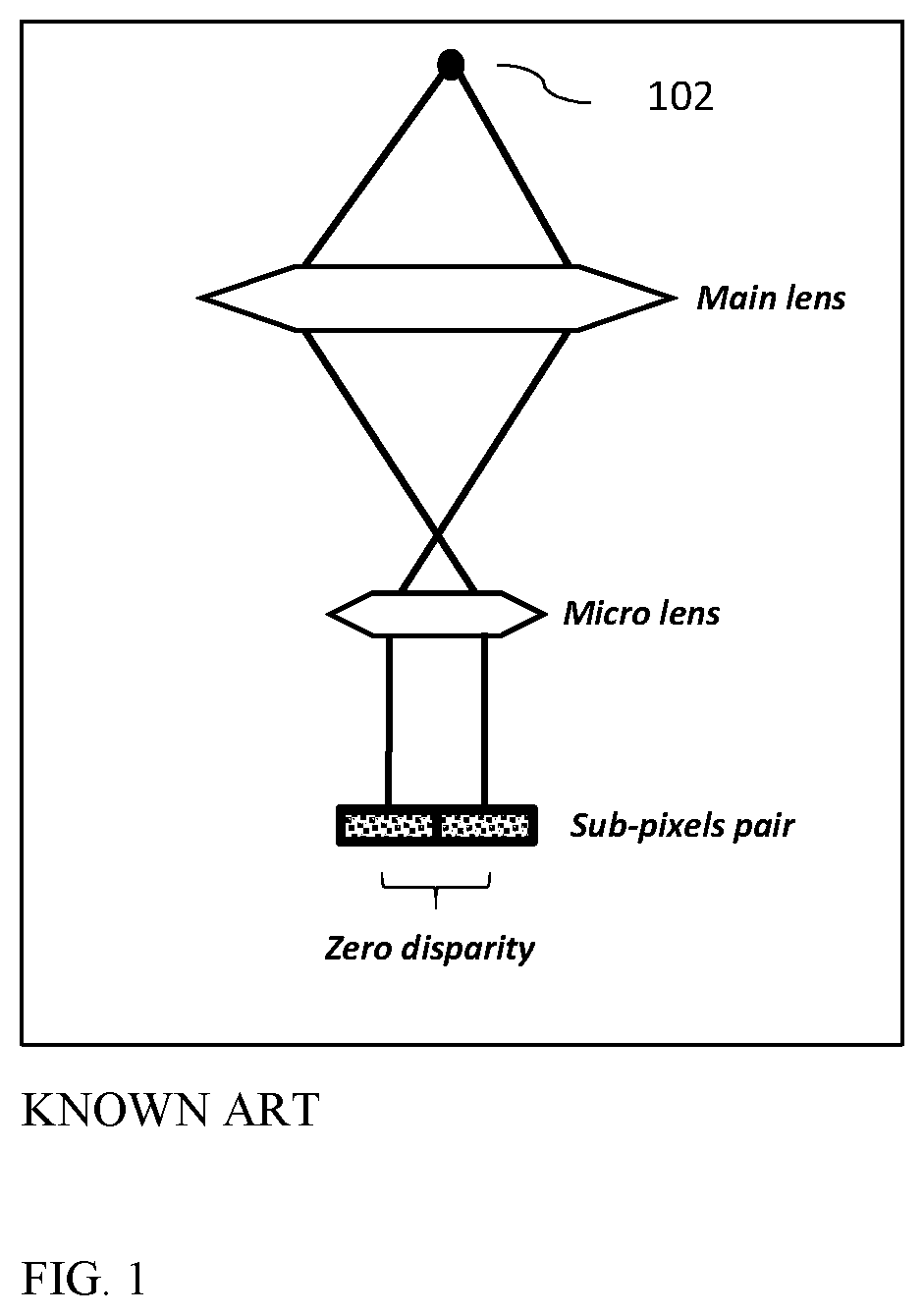
A depth map obtained with a dual-aperture camera is referred to as "stereoscopic" depth map. In some dual-aperture cameras, one ("reference") camera is equipped with a Wide lens and with a Phase-Detection (PD) sensor. The second camera is equipped with a Tele lens, so that the overlapping field of view of the two cameras is partial relative to the FOV reference camera. The region of the Tele FOV that overlaps the Wide FOV is referred to as "overlap region". All regions in the Wide FOV that are not overlapped by the Tele FOV are referred to as "non-overlap regions". Alternatively, in some embodiments both cameras may be equipped with a 2PD sensor, i.e. a sensor in which each sensor pixel is divided into 2 sub-pixels and supports depth estimation via calculation of disparity between the image produced by all the right sub-pixels and that produced by all left sub-pixels. PD sensors take advantage of multiple micro-lenses (or partially covered micro-lenses) to detect pixels in and out of focus. Micro-lenses are calibrated so that objects in focus are projected onto the sensor plane at the same location relative to the lens, see FIG. 1.
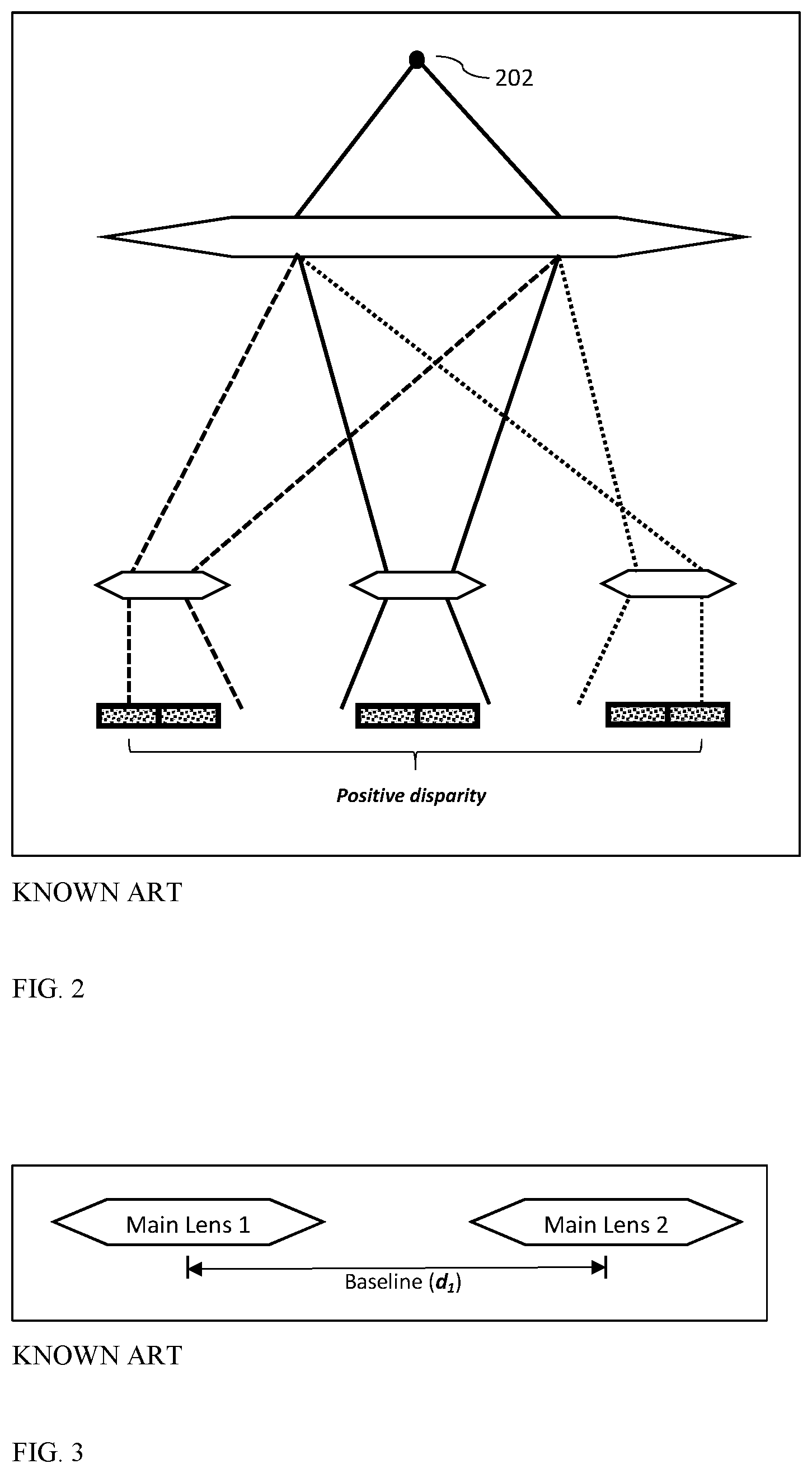
FIG. 1 shows a point object 102 in focus, with a micro-lens projecting the light from the object onto the center of two sub-pixels, causing zero-disparity. FIG. 2 shows light-rays from a point object 202 out of focus. The left micro-lens projects the light from the object onto the center of the left sub-pixel. The right micro-lens projects the same object onto the right sub-pixel, causing a positive disparity value of 2, which is not directly related to the true distance of the object from the sensor. Objects before/after the focal plane are projected to different locations relative to each lens, creating a positive/negative disparity between the projections. As stated above, this disparity is zero for the focal plane and increases in magnitude as the object moves further away from that plane. The 2PD disparity information can be used to create a "2PD depth map". Note that this 2PD depth map is both crude (due to a very small baseline) and relative to the focal plane. That is, zero-disparity is detected for objects in focus, rather than for objects at infinity.
All known methods to obtain depth maps using dual or multi-aperture cameras suffer from the problem that while the depth map is accurate in an overlap region, it is inaccurate in the non-overlap region. For camera arrays where the FOV of the modules is different (e.g. dual- or multi-aperture cameras with Wide and Tele lenses), a fine and absolute depth map can be extracted only for the overlap region using mainly the stereoscopic information. No absolute depth map can be obtained for the non-overlap regions. There is therefore a need for and it would be advantageous to have systems and methods to extend the absolute depth information to the non-overlap regions as well. Further, it would be advantageous to enhance the accuracy of the depth map in the overlap region, by relying on additional information from 2PD sensor(s).
SUMMARY
In an exemplary embodiment there is provided a method comprising providing an imaging system having a first camera with a first FOV and a second camera with a second FOV smaller than the first FOV, wherein the first FOV and the second FOV overlap over an overlap region, calculating a stereoscopic depth map in the overlap region using respective image information provided by the first and second cameras, obtaining a first camera 2 sub-pixel phase detection (2PD) disparity map in the entire first FOV, and improving the stereoscopic depth map or the 2PD depth map in at least the overlap region using the stereoscopic depth map in the overlap region and/or the first camera 2PD disparity map in the entire first FOV.
In an exemplary embodiment, the improving the stereoscopic depth map or the 2PD depth map in at least the overlap region includes using the stereoscopic depth map in the overlap region and/or the first camera 2PD disparity map in the entire first FOV to provide a calibrated 2PD depth map in the entire first FOV.
In an exemplary embodiment, the calculating a stereoscopic depth map in the overlap region includes calculating an absolute stereoscopic depth map in the overlap region.
In an exemplary embodiment, the calculating an absolute stereoscopic depth map in the overlap region includes cropping the image information provided by the first camera to match the second FOV so that disparity at infinity is zero.
In an exemplary embodiment, the using the stereoscopic depth map in the overlap region and the first camera 2PD disparity map in the entire first FOV to provide a calibrated PD depth map in the entire first FOV includes converting disparities in the first camera 2PD disparity map in the entire first FOV from pixel units into calibrated physical units based on the calibrated result of a stereo disparity.
In an exemplary embodiment, the improving the stereoscopic depth map or the 2PD depth map in at least the overlap region includes using the 2PD depth map to improve the stereoscopic depth map in the overlap region.
In an exemplary embodiment, the obtaining a 2PD depth map in the entire first FOV includes obtaining the 2PD depth map using a first camera image sensor.
In an exemplary embodiment, the obtaining a 2PD depth map in the entire first FOV includes obtaining the 2PD depth map using a first camera image sensor and a second camera image sensor.
BRIEF DESCRIPTION OF THE DRAWINGS
Non-limiting examples of embodiments disclosed herein are described below with reference to figures attached hereto that are listed following this paragraph. The drawings and descriptions are meant to illuminate and clarify embodiments disclosed herein, and should not be considered limiting in any way. Like elements in different drawings may be indicated by like numerals. Elements in the drawings are not necessarily drawn to scale.
FIG. 2 shows an object in focus, with a micro-lens projecting the light from the object onto the center of two sub-pixels, causing zero-disparity;
FIG. 3 shows an object out of focus, with a left micro-lens projecting the light from the object onto the center of the left sub-pixel and a right micro-lens projecting the same object onto the center of the right sub-pixel, causing a positive disparity value of 2, which has no physical meaning of the true object distance;
FIG. 3 shows an exemplary baseline (d.sub.1) between two cameras used for stereoscopic depth calculation;
FIG. 4 shows on the left an exemplary disparity map obtained from the 2PD sensor and on the right the disparity map for the same image generated using a stereoscopic method;
FIG. 5 shows an exemplary baseline (d.sub.2) used for 2PD depth calculation;
FIG. 6 shows in a flow chart an exemplary embodiment of a method disclosed herein;
FIG. 7 shows in (a) an exemplary disparity map for an image generated using a 2PD sensor and on the right, in (b) the disparity map for the same image generated using a stereoscopic method, and in (c) a calibrated result with physical distance units as produced by the method described in the flow chart of FIG. 6.
DETAILED DESCRIPTION
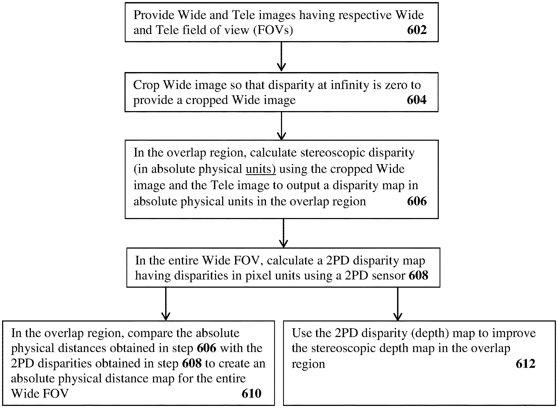
An exemplary embodiment of a method to extend the absolute depth information obtained by stereoscopic vision in the overlap region to the non-overlap region as well is described next, with reference to FIG. 6. In the exemplary embodiment, the method includes:
In a step 602, provide Wide and Tele images having respective Wide and Tele field of view (FOVs)
In a step 604, crop the Wide image so that disparity at infinity is zero to provide a cropped Wide image. This prepares the Wide camera image for depth calculation.
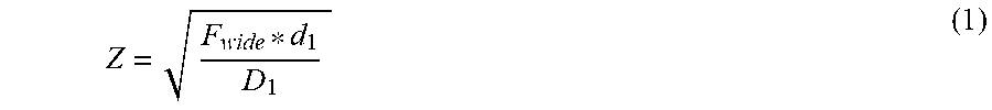
In a step 606, calculate stereoscopic disparity (in absolute physical units) in the overlap region using the cropped Wide image and the Tele image to output a disparity map in absolute physical units in the overlap region. Such a disparity map has zero-disparity at infinity and in general follows equation 1:
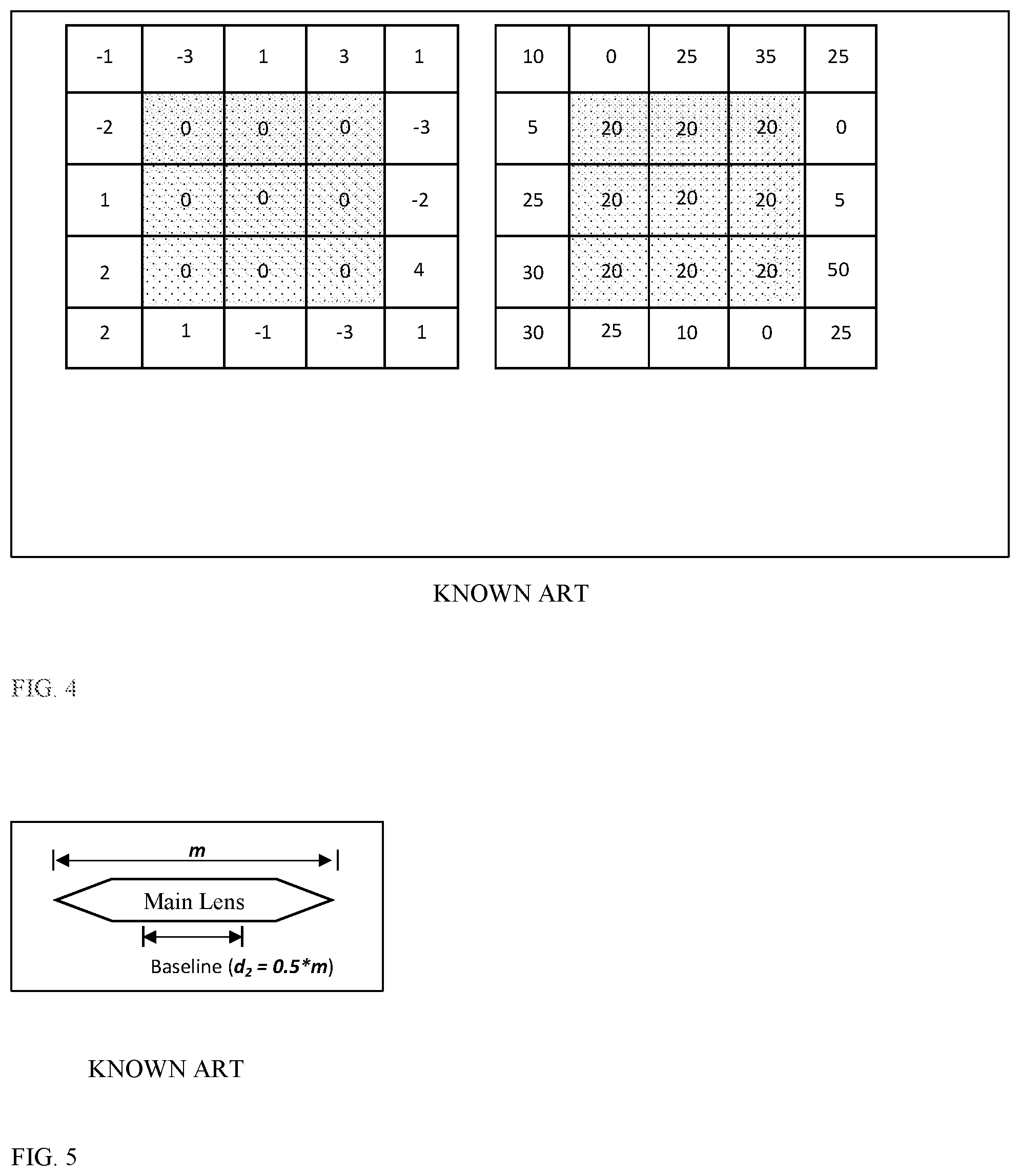
##EQU00001## where Z is the reference (in this case Wide) camera-to-object distance in physical units (e.g. in mm), F.sub.wide the focal length of the Wide camera, d.sub.1 the distance between the centers of the main lenses (baseline) and D.sub.1 is the disparity in pixels (see FIG. 3 for more details). For example, d.sub.1=10 mm. Equation 1 provides stereoscopic conversion from disparity in pixel units to distance in physical units. Note that this equation is true for optimal conditions, which can be obtained by applying a known calibration process. In a step 608, calculate a 2PD disparity map with disparities in pixel units in the entire Wide FOV using a 2PD sensor. FIG. 4 shows on the left an exemplary 2PD disparity map obtained from a 2PD sensor: the central region (marked with dots) is in focus and thus has zero disparity (pixel units). Other pixels have different disparity values, i.e. are out of focus, but their camera-to-object distance is unknown. On the right, FIG. 4 shows a disparity map for the same image generated using a known stereoscopic method the disparity in pixels is zero for objects at infinity and increases as the object distance from the camera decreases. Thus, the 2PD disparity values can be converted to the physical camera-to-object distances. Disparities in the stereoscopic map are much larger, as the baseline is larger (d.sub.2<d.sub.1). The 2PD disparities may be converted from pixel units to distance in physical units using Equation 2.
##EQU00002## where Z is the camera-to-object distance in physical units (e.g. mm), F.sub.wide the focal length of the Wide camera, d.sub.2 is approximately equal to 0.5.times.m where m is the diameter of the wide camera lens aperture and, D.sub.infinity is the disparity of objects at infinity and D.sub.2 the disparity in pixels, dependent on focal position (see FIG. 5 for more details). For example, m=2 mm. Note that D.sub.infinity depends on the focus position. In a step 610, compare the absolute stereoscopic physical distances obtained in step 606 with the 2PD disparities obtained in step 608 in the overlap region to create an absolute physical distance map for the entire Wide FOV For a given pixel in the overlap region, its camera-to-object distance in physical units (Z), should be identical for both (stereoscopic and 2PD) methods Based on equation 1 and equation 2, D.sub.infinity is found using equation 3:
.times. ##EQU00003## Using D.sub.infinity, the disparities in the non-overlap region can now be converted into calibrated physical units, by applying equation 2.
FIG. 7 shows in (a) an exemplary disparity map for an image generated using a 2PD sensor and in (b) the disparity map for the same image generated using a stereoscopic method. Both (a) and (b) show disparities (offsets) in units of pixel. FIG. 7 shows in (c) a calibrated depth map obtained over the entire Wide FOV with a method disclosed herein, with physical distance units (e.g. cm). The dotted areas in (a), (b) and (c) represent the overlap region.
Alternatively or in addition to the extension of the absolute depth information obtained by stereoscopic vision in the overlap region to the non-overlap region, one may use the 2PD disparity map from step 608 above to enhance the result of stereoscopic disparity, step 612. The 2PD disparities may be obtained from the Wide camera alone, of from both the Wide and Tele cameras. The 2PD disparity map can be used to define a local search range for the stereoscopic algorithm. 2PD disparity can be calculated along a vertical (e.g. Y) axis, while stereoscopic disparity can be calculated along a horizontal (e.g. X) axis, or vice-versa (depending on hardware assembly). Objects lying along a single axis will be better detected by one calculation than by the other (i.e. by 2PD disparity vs. stereoscopic disparity or vice versa). Such objects are detected and greater reliability is assigned to the appropriate choice.
The level of disagreement between the depth calculated by the 2PD disparity and the depth calculated by stereoscopic disparity algorithms can be used as a reliability measure per pixel. For example, after the calibration of the 2PD disparity map (using steps 600-610 above for the overlap region only), one may compare the depth calculated by both methods. In case of significant disagreement (for example, if the stereoscopic disparity method can reach an accuracy of .+-.1 pixel, "significant disagreement" may be defined as more than 2 pixels), this depth value can be considered unreliable and marked as an outlier.
In conclusion, using either steps 600-610 or steps 600-608 plus the enhancement of stereoscopic disparity described above, the entire FOV of the Wide camera will have absolute disparity values (i.e. true physical distance to an object), with the overlap region obtaining these absolute values from the stereoscopic+2PD values and the non-overlap region obtaining these absolute values based on Equation 3.
While this disclosure has been described in terms of certain embodiments and generally associated methods, alterations and permutations of the embodiments and methods will be apparent to those skilled in the art. For example, while the usage of 2 cameras for depth calculation is described in some detail, depth information may be extracted from multiple (>2) cameras as well. The disclosure is to be understood as not limited by the specific embodiments described herein.
All references mentioned in this application are hereby incorporated by reference in their entirety for all purposes set forth herein. It is emphasized that citation or identification of any reference in this application shall not be construed as an admission that such a reference is available or admitted as prior art.
* * * * *
D00000
D00001
D00002
D00003
D00004
D00005
M00001
M00002
M00003
XML
uspto.report is an independent third-party trademark research tool that is not affiliated, endorsed, or sponsored by the United States Patent and Trademark Office (USPTO) or any other governmental organization. The information provided by uspto.report is based on publicly available data at the time of writing and is intended for informational purposes only.
While we strive to provide accurate and up-to-date information, we do not guarantee the accuracy, completeness, reliability, or suitability of the information displayed on this site. The use of this site is at your own risk. Any reliance you place on such information is therefore strictly at your own risk.
All official trademark data, including owner information, should be verified by visiting the official USPTO website at www.uspto.gov. This site is not intended to replace professional legal advice and should not be used as a substitute for consulting with a legal professional who is knowledgeable about trademark law.