Container networking using communication tunnels
Tollet , et al. January 26, 2
U.S. patent number 10,904,342 [Application Number 16/049,401] was granted by the patent office on 2021-01-26 for container networking using communication tunnels. This patent grant is currently assigned to CISCO TECHNOLOGY, INC.. The grantee listed for this patent is Cisco Technology, Inc.. Invention is credited to Keith Burns, Giles Douglas Yorke Heron, Andre Jean-Marie Surcouf, Jerome Tollet.


| United States Patent | 10,904,342 |
| Tollet , et al. | January 26, 2021 |
Container networking using communication tunnels
Abstract
Systems, methods, and computer-readable media for enabling container networking are disclosed. In one aspect, a method includes receiving a request from a first network container on a source server to establish a data session with a second network container on a destination server; determining a destination switch of the destination server based on the request; identifying a communication tunnel between the source server and the destination server; generating a data stream to be embedded in the pre-established communication tunnel, wherein a communication protocol associated with the request is different from a communication protocol used by the data stream; receiving a data packet to be sent to the destination container; mapping the data packet to the data stream; and sending the data packet to the destination server via the data stream over the communication tunnel.
| Inventors: | Tollet; Jerome (Paris, FR), Heron; Giles Douglas Yorke (London, GB), Burns; Keith (San Jose, CA), Surcouf; Andre Jean-Marie (St. Leu la Foret, FR) | ||||||||||
|---|---|---|---|---|---|---|---|---|---|---|---|
| Applicant: |
|
||||||||||
| Assignee: | CISCO TECHNOLOGY, INC. (San
Jose, CA) |
||||||||||
| Appl. No.: | 16/049,401 | ||||||||||
| Filed: | July 30, 2018 |
Prior Publication Data
| Document Identifier | Publication Date | |
|---|---|---|
| US 20200036796 A1 | Jan 30, 2020 | |
| Current U.S. Class: | 1/1 |
| Current CPC Class: | G06F 9/547 (20130101); H04L 67/141 (20130101); H04L 63/029 (20130101) |
| Current International Class: | G06F 15/16 (20060101); H04L 29/08 (20060101); G06F 9/54 (20060101); H04L 29/06 (20060101) |
References Cited [Referenced By]
U.S. Patent Documents
| 5812773 | September 1998 | Norin |
| 5825772 | October 1998 | Dobbins |
| 5889896 | March 1999 | Meshinsky et al. |
| 6108782 | August 2000 | Fletcher et al. |
| 6178453 | January 2001 | Mattaway et al. |
| 6298153 | October 2001 | Oishi |
| 6343290 | January 2002 | Cossins et al. |
| 6643260 | November 2003 | Kloth et al. |
| 6683873 | January 2004 | Kwok et al. |
| 6721804 | April 2004 | Rubin et al. |
| 6733449 | May 2004 | Krishnamurthy et al. |
| 6735631 | May 2004 | Oehrke et al. |
| 6996615 | February 2006 | McGuire |
| 7054930 | May 2006 | Cheriton |
| 7058706 | June 2006 | Lyer et al. |
| 7062571 | June 2006 | Dale et al. |
| 7111177 | September 2006 | Chauvel et al. |
| 7212490 | May 2007 | Kao et al. |
| 7277948 | October 2007 | Igarashi et al. |
| 7313667 | December 2007 | Pullela et al. |
| 7379846 | May 2008 | Williams et al. |
| 7480672 | January 2009 | Hahn et al. |
| 7496043 | February 2009 | Leong et al. |
| 7536476 | May 2009 | Alleyne |
| 7567504 | July 2009 | Darling et al. |
| 7583665 | September 2009 | Duncan et al. |
| 7606147 | October 2009 | Luft et al. |
| 7606929 | October 2009 | Gbadegesin |
| 7644437 | January 2010 | Volpano |
| 7647594 | January 2010 | Togawa |
| 7773510 | August 2010 | Back et al. |
| 7808897 | October 2010 | Mehta et al. |
| 7881957 | February 2011 | Cohen et al. |
| 7917647 | March 2011 | Cooper et al. |
| 8010598 | August 2011 | Tanimoto |
| 8028071 | September 2011 | Mahalingam et al. |
| 8041714 | October 2011 | Aymeloglu et al. |
| 8121117 | February 2012 | Amdahl et al. |
| 8171415 | May 2012 | Appleyard et al. |
| 8234377 | July 2012 | Cohn |
| 8244559 | August 2012 | Horvitz et al. |
| 8250215 | August 2012 | Stienhans et al. |
| 8280880 | October 2012 | Aymeloglu et al. |
| 8284664 | October 2012 | Aybay et al. |
| 8301746 | October 2012 | Head et al. |
| 8345692 | January 2013 | Smith |
| 8406141 | March 2013 | Couturier et al. |
| 8407413 | March 2013 | Yucel et al. |
| 8448171 | May 2013 | Donnellan et al. |
| 8477610 | July 2013 | Zuo et al. |
| 8495356 | July 2013 | Ashok et al. |
| 8495725 | July 2013 | Ahn |
| 8510469 | August 2013 | Portolani |
| 8514868 | August 2013 | Hill |
| 8532108 | September 2013 | Li et al. |
| 8533687 | September 2013 | Greifeneder et al. |
| 8547974 | October 2013 | Guruswamy et al. |
| 8560639 | October 2013 | Murphy et al. |
| 8560663 | October 2013 | Baucke et al. |
| 8589543 | November 2013 | Dutta et al. |
| 8590050 | November 2013 | Nagpal et al. |
| 8611356 | December 2013 | Yu et al. |
| 8612625 | December 2013 | Andreis et al. |
| 8630291 | January 2014 | Shaffer et al. |
| 8639787 | January 2014 | Lagergren et al. |
| 8656024 | February 2014 | Krishnan et al. |
| 8660129 | February 2014 | Brendel et al. |
| 8719804 | May 2014 | Jain |
| 8775576 | July 2014 | Hebert et al. |
| 8797867 | August 2014 | Chen et al. |
| 8805951 | August 2014 | Faibish et al. |
| 8850002 | September 2014 | Dickinson et al. |
| 8850182 | September 2014 | Fritz et al. |
| 8856339 | October 2014 | Mestery et al. |
| 8909928 | December 2014 | Ahmad et al. |
| 8918510 | December 2014 | Gmach et al. |
| 8924720 | December 2014 | Raghuram et al. |
| 8930747 | January 2015 | Levijarvi et al. |
| 8938775 | January 2015 | Roth et al. |
| 8959526 | February 2015 | Kansal et al. |
| 8977754 | March 2015 | Curry, Jr. et al. |
| 9009697 | April 2015 | Breiter et al. |
| 9015324 | April 2015 | Jackson |
| 9043439 | May 2015 | Bicket et al. |
| 9049115 | June 2015 | Rajendran et al. |
| 9063789 | June 2015 | Beaty et al. |
| 9065727 | June 2015 | Liu et al. |
| 9075649 | July 2015 | Bushman et al. |
| 9130846 | September 2015 | Szabo et al. |
| 9164795 | October 2015 | Vincent |
| 9167050 | October 2015 | Durazzo et al. |
| 9201701 | December 2015 | Boldyrev et al. |
| 9201704 | December 2015 | Chang et al. |
| 9203784 | December 2015 | Chang et al. |
| 9223634 | December 2015 | Chang et al. |
| 9244776 | January 2016 | Koza et al. |
| 9251114 | February 2016 | Ancin et al. |
| 9264478 | February 2016 | Hon et al. |
| 9294408 | March 2016 | Dickinson et al. |
| 9313048 | April 2016 | Chang et al. |
| 9361192 | June 2016 | Smith et al. |
| 9379982 | June 2016 | Krishna et al. |
| 9380075 | June 2016 | He et al. |
| 9432245 | August 2016 | Sorenson, III et al. |
| 9432294 | August 2016 | Sharma et al. |
| 9444744 | September 2016 | Sharma et al. |
| 9473365 | October 2016 | Melander et al. |
| 9503530 | November 2016 | Niedzielski |
| 9558078 | January 2017 | Farlee et al. |
| 9571570 | February 2017 | Mutnuru |
| 9613078 | April 2017 | Vermeulen et al. |
| 9628471 | April 2017 | Sundaram et al. |
| 9658876 | May 2017 | Chang et al. |
| 9692802 | June 2017 | Bicket et al. |
| 9755858 | September 2017 | Bagepalli et al. |
| 9847938 | December 2017 | Chanda et al. |
| 10498654 | December 2019 | Shalev |
| 10516496 | December 2019 | Kits van Heyningen |
| 2001/0055303 | December 2001 | Horton et al. |
| 2002/0073337 | June 2002 | Ioele et al. |
| 2002/0143928 | October 2002 | Maltz et al. |
| 2002/0166117 | November 2002 | Abrams et al. |
| 2002/0174216 | November 2002 | Shorey et al. |
| 2003/0018591 | January 2003 | Komisky |
| 2003/0056001 | March 2003 | Mate et al. |
| 2003/0228585 | December 2003 | Inoko et al. |
| 2004/0004941 | January 2004 | Malan et al. |
| 2004/0034702 | February 2004 | He |
| 2004/0088542 | May 2004 | Daude et al. |
| 2004/0095237 | May 2004 | Chen et al. |
| 2004/0131059 | July 2004 | Ayyakad et al. |
| 2004/0197079 | October 2004 | Latvala et al. |
| 2004/0264481 | December 2004 | Darling et al. |
| 2005/0060418 | March 2005 | Sorokopud |
| 2005/0125424 | June 2005 | Herriott et al. |
| 2006/0062187 | March 2006 | Rune |
| 2006/0104286 | May 2006 | Cheriton |
| 2006/0126665 | June 2006 | Ward et al. |
| 2006/0146825 | July 2006 | Hofstaedter et al. |
| 2006/0155875 | July 2006 | Cheriton |
| 2006/0168338 | July 2006 | Bruegl et al. |
| 2006/0233106 | October 2006 | Achlioptas et al. |
| 2007/0174663 | July 2007 | Crawford et al. |
| 2007/0223487 | September 2007 | Kajekar et al. |
| 2007/0242830 | October 2007 | Conrado et al. |
| 2008/0005293 | January 2008 | Bhargava et al. |
| 2008/0080524 | April 2008 | Tsushima et al. |
| 2008/0084880 | April 2008 | Dharwadkar |
| 2008/0165778 | July 2008 | Ertemalp |
| 2008/0198752 | August 2008 | Fan et al. |
| 2008/0198858 | August 2008 | Townsley et al. |
| 2008/0201711 | August 2008 | Amir Husain |
| 2008/0235755 | September 2008 | Blaisdell et al. |
| 2009/0006527 | January 2009 | Gingell, Jr. et al. |
| 2009/0019367 | January 2009 | Cavagnari et al. |
| 2009/0031312 | January 2009 | Mausolf et al. |
| 2009/0083183 | March 2009 | Rao et al. |
| 2009/0138763 | May 2009 | Arnold |
| 2009/0177775 | July 2009 | Radia et al. |
| 2009/0178058 | July 2009 | Stillwell, III et al. |
| 2009/0182874 | July 2009 | Morford et al. |
| 2009/0265468 | October 2009 | Annambhotla et al. |
| 2009/0265753 | October 2009 | Anderson et al. |
| 2009/0293056 | November 2009 | Ferris |
| 2009/0300608 | December 2009 | Ferris et al. |
| 2009/0313562 | December 2009 | Appleyard et al. |
| 2009/0323706 | December 2009 | Germain et al. |
| 2009/0328031 | December 2009 | Pouyadou et al. |
| 2010/0036903 | February 2010 | Ahmad et al. |
| 2010/0042720 | February 2010 | Stienhans et al. |
| 2010/0061250 | March 2010 | Nugent |
| 2010/0115341 | May 2010 | Baker et al. |
| 2010/0131765 | May 2010 | Bromley et al. |
| 2010/0149966 | June 2010 | Achlioptas et al. |
| 2010/0191783 | July 2010 | Mason et al. |
| 2010/0192157 | July 2010 | Jackson et al. |
| 2010/0205601 | August 2010 | Abbas et al. |
| 2010/0211782 | August 2010 | Auradkar et al. |
| 2010/0293270 | November 2010 | Augenstein et al. |
| 2010/0318609 | December 2010 | Lahiri et al. |
| 2010/0325199 | December 2010 | Park et al. |
| 2010/0325441 | December 2010 | Laurie et al. |
| 2010/0333116 | December 2010 | Prahlad et al. |
| 2011/0016214 | January 2011 | Jackson |
| 2011/0035754 | February 2011 | Srinivasan |
| 2011/0055396 | March 2011 | Dehaan |
| 2011/0055398 | March 2011 | Dehaan et al. |
| 2011/0055470 | March 2011 | Portolani |
| 2011/0072489 | March 2011 | Parann-Nissany |
| 2011/0075667 | March 2011 | Li et al. |
| 2011/0110382 | May 2011 | Jabr et al. |
| 2011/0116443 | May 2011 | Yu et al. |
| 2011/0126099 | May 2011 | Anderson et al. |
| 2011/0138055 | June 2011 | Daly et al. |
| 2011/0145413 | June 2011 | Dawson et al. |
| 2011/0145657 | June 2011 | Bishop et al. |
| 2011/0173303 | July 2011 | Rider |
| 2011/0185063 | July 2011 | Head et al. |
| 2011/0185065 | July 2011 | Stanisic et al. |
| 2011/0206052 | August 2011 | Tan et al. |
| 2011/0213966 | September 2011 | Fu et al. |
| 2011/0219434 | September 2011 | Betz et al. |
| 2011/0231715 | September 2011 | Kunii et al. |
| 2011/0231899 | September 2011 | Pulier et al. |
| 2011/0239039 | September 2011 | Dieffenbach et al. |
| 2011/0252327 | October 2011 | Awasthi et al. |
| 2011/0261811 | October 2011 | Battestilli et al. |
| 2011/0261828 | October 2011 | Smith |
| 2011/0276675 | November 2011 | Singh et al. |
| 2011/0276951 | November 2011 | Jain |
| 2011/0283013 | November 2011 | Grosser et al. |
| 2011/0295998 | December 2011 | Ferris et al. |
| 2011/0305149 | December 2011 | Scott et al. |
| 2011/0307531 | December 2011 | Gaponenko et al. |
| 2011/0320870 | December 2011 | Kenigsberg et al. |
| 2012/0005724 | January 2012 | Lee |
| 2012/0036234 | February 2012 | Staats et al. |
| 2012/0054367 | March 2012 | Ramakrishnan et al. |
| 2012/0072318 | March 2012 | Akiyama et al. |
| 2012/0072578 | March 2012 | Alam |
| 2012/0072581 | March 2012 | Tung et al. |
| 2012/0072985 | March 2012 | Davne et al. |
| 2012/0072992 | March 2012 | Arasaratnam et al. |
| 2012/0084445 | April 2012 | Brock et al. |
| 2012/0084782 | April 2012 | Chou et al. |
| 2012/0096134 | April 2012 | Suit |
| 2012/0102193 | April 2012 | Rathore et al. |
| 2012/0102199 | April 2012 | Hopmann et al. |
| 2012/0131174 | May 2012 | Ferris et al. |
| 2012/0137215 | May 2012 | Kawara |
| 2012/0158967 | June 2012 | Sedayao et al. |
| 2012/0159097 | June 2012 | Jennas, II et al. |
| 2012/0167094 | June 2012 | Suit |
| 2012/0173710 | July 2012 | Rodriguez |
| 2012/0179909 | July 2012 | Sagi et al. |
| 2012/0180044 | July 2012 | Donnellan et al. |
| 2012/0182891 | July 2012 | Lee et al. |
| 2012/0185913 | July 2012 | Martinez et al. |
| 2012/0192016 | July 2012 | Gotesdyner et al. |
| 2012/0192075 | July 2012 | Ebtekar et al. |
| 2012/0201135 | August 2012 | Ding et al. |
| 2012/0214506 | August 2012 | Skaaksrud et al. |
| 2012/0222106 | August 2012 | Kuehl |
| 2012/0236716 | September 2012 | Anbazhagan et al. |
| 2012/0240113 | September 2012 | Hur |
| 2012/0265976 | October 2012 | Spiers et al. |
| 2012/0272025 | October 2012 | Park et al. |
| 2012/0281706 | November 2012 | Agarwal et al. |
| 2012/0281708 | November 2012 | Chauhan et al. |
| 2012/0290647 | November 2012 | Ellison et al. |
| 2012/0297238 | November 2012 | Watson et al. |
| 2012/0311106 | December 2012 | Morgan |
| 2012/0311568 | December 2012 | Jansen |
| 2012/0324092 | December 2012 | Brown et al. |
| 2012/0324114 | December 2012 | Dutta et al. |
| 2013/0003567 | January 2013 | Gallant et al. |
| 2013/0013248 | January 2013 | Brugler et al. |
| 2013/0036213 | February 2013 | Hasan et al. |
| 2013/0044636 | February 2013 | Koponen et al. |
| 2013/0066940 | March 2013 | Shao |
| 2013/0080509 | March 2013 | Wang |
| 2013/0080624 | March 2013 | Nagai et al. |
| 2013/0091557 | April 2013 | Gurrapu |
| 2013/0097601 | April 2013 | Podvratnik et al. |
| 2013/0104140 | April 2013 | Meng et al. |
| 2013/0111540 | May 2013 | Sabin |
| 2013/0117337 | May 2013 | Dunham |
| 2013/0124712 | May 2013 | Parker |
| 2013/0125124 | May 2013 | Kempf et al. |
| 2013/0138816 | May 2013 | Kuo et al. |
| 2013/0144978 | June 2013 | Jain et al. |
| 2013/0152076 | June 2013 | Patel |
| 2013/0152175 | June 2013 | Hromoko et al. |
| 2013/0159097 | June 2013 | Schory et al. |
| 2013/0159496 | June 2013 | Hamilton et al. |
| 2013/0160008 | June 2013 | Cawlfield et al. |
| 2013/0162753 | June 2013 | Hendrickson et al. |
| 2013/0169666 | July 2013 | Pacheco et al. |
| 2013/0179941 | July 2013 | McGloin et al. |
| 2013/0182712 | July 2013 | Aguayo et al. |
| 2013/0185433 | July 2013 | Zhu et al. |
| 2013/0191106 | July 2013 | Kephart et al. |
| 2013/0198374 | August 2013 | Zalmanovitch et al. |
| 2013/0201989 | August 2013 | Hu et al. |
| 2013/0204849 | August 2013 | Chacko |
| 2013/0232491 | September 2013 | Radhakrishnan et al. |
| 2013/0246588 | September 2013 | Borowicz et al. |
| 2013/0250770 | September 2013 | Zou et al. |
| 2013/0254415 | September 2013 | Fullen et al. |
| 2013/0262347 | October 2013 | Dodson |
| 2013/0283364 | October 2013 | Chang et al. |
| 2013/0297769 | November 2013 | Chang et al. |
| 2013/0318240 | November 2013 | Hebert et al. |
| 2013/0318546 | November 2013 | Kothuri et al. |
| 2013/0339949 | December 2013 | Spiers et al. |
| 2014/0006481 | January 2014 | Frey et al. |
| 2014/0006535 | January 2014 | Reddy |
| 2014/0006585 | January 2014 | Dunbar et al. |
| 2014/0040473 | February 2014 | Ho et al. |
| 2014/0040883 | February 2014 | Tompkins |
| 2014/0052877 | February 2014 | Mao |
| 2014/0056146 | February 2014 | Hu et al. |
| 2014/0059310 | February 2014 | Du et al. |
| 2014/0074850 | March 2014 | Noel et al. |
| 2014/0075048 | March 2014 | Yuksel et al. |
| 2014/0075108 | March 2014 | Dong et al. |
| 2014/0075357 | March 2014 | Flores et al. |
| 2014/0075501 | March 2014 | Srinivasan et al. |
| 2014/0089727 | March 2014 | Cherkasova et al. |
| 2014/0098762 | April 2014 | Ghai et al. |
| 2014/0108985 | April 2014 | Scott et al. |
| 2014/0122560 | May 2014 | Ramey et al. |
| 2014/0136779 | May 2014 | Guha et al. |
| 2014/0140211 | May 2014 | Chandrasekaran et al. |
| 2014/0141720 | May 2014 | Princen et al. |
| 2014/0156557 | June 2014 | Zeng et al. |
| 2014/0164486 | June 2014 | Ravichandran et al. |
| 2014/0188825 | July 2014 | Muthukkaruppan et al. |
| 2014/0189095 | July 2014 | Lindberg et al. |
| 2014/0189125 | July 2014 | Amies et al. |
| 2014/0215471 | July 2014 | Cherkasova |
| 2014/0222953 | August 2014 | Karve et al. |
| 2014/0233384 | August 2014 | Howard |
| 2014/0244851 | August 2014 | Lee |
| 2014/0245298 | August 2014 | Zhou et al. |
| 2014/0281173 | September 2014 | Im et al. |
| 2014/0282536 | September 2014 | Dave et al. |
| 2014/0282611 | September 2014 | Campbell et al. |
| 2014/0282889 | September 2014 | Ishaya et al. |
| 2014/0289200 | September 2014 | Kato |
| 2014/0295831 | October 2014 | Karra et al. |
| 2014/0297569 | October 2014 | Clark et al. |
| 2014/0297835 | October 2014 | Buys |
| 2014/0310391 | October 2014 | Sorensen, III et al. |
| 2014/0310417 | October 2014 | Sorensen, III et al. |
| 2014/0310418 | October 2014 | Sorensen, III et al. |
| 2014/0314078 | October 2014 | Jilani |
| 2014/0317261 | October 2014 | Shatzkamer et al. |
| 2014/0321278 | October 2014 | Cafarelli et al. |
| 2014/0330976 | November 2014 | van Bemmel |
| 2014/0330977 | November 2014 | van Bemmel |
| 2014/0334488 | November 2014 | Guichard et al. |
| 2014/0362682 | December 2014 | Guichard et al. |
| 2014/0365680 | December 2014 | van Bemmel |
| 2014/0366155 | December 2014 | Chang et al. |
| 2014/0369204 | December 2014 | Anand et al. |
| 2014/0372567 | December 2014 | Ganesh et al. |
| 2014/0379938 | December 2014 | Bosch et al. |
| 2015/0033086 | January 2015 | Sasturkar et al. |
| 2015/0043576 | February 2015 | Dixon et al. |
| 2015/0052247 | February 2015 | Threefoot et al. |
| 2015/0052517 | February 2015 | Raghu et al. |
| 2015/0058382 | February 2015 | St. Laurent et al. |
| 2015/0058459 | February 2015 | Amendjian et al. |
| 2015/0071285 | March 2015 | Kumar et al. |
| 2015/0085870 | March 2015 | Narasimha et al. |
| 2015/0089082 | March 2015 | Patwardhan et al. |
| 2015/0100471 | April 2015 | Curry, Jr. et al. |
| 2015/0103827 | April 2015 | Quinn et al. |
| 2015/0106802 | April 2015 | Ivanov et al. |
| 2015/0106805 | April 2015 | Melander et al. |
| 2015/0117199 | April 2015 | Chinnaiah Sankaran et al. |
| 2015/0117458 | April 2015 | Gurkan et al. |
| 2015/0120914 | April 2015 | Wada et al. |
| 2015/0124622 | May 2015 | Kovvali et al. |
| 2015/0138973 | May 2015 | Kumar et al. |
| 2015/0178133 | June 2015 | Phelan et al. |
| 2015/0189009 | July 2015 | van Bemmel |
| 2015/0215819 | July 2015 | Bosch et al. |
| 2015/0227405 | August 2015 | Jan et al. |
| 2015/0242204 | August 2015 | Hassine et al. |
| 2015/0249709 | September 2015 | Teng et al. |
| 2015/0263901 | September 2015 | Kumar et al. |
| 2015/0280980 | October 2015 | Bitar |
| 2015/0281067 | October 2015 | Wu |
| 2015/0281113 | October 2015 | Siciliano et al. |
| 2015/0309908 | October 2015 | Pearson et al. |
| 2015/0319063 | November 2015 | Zourzouvillys et al. |
| 2015/0326524 | November 2015 | Tankala et al. |
| 2015/0339210 | November 2015 | Kopp et al. |
| 2015/0358850 | December 2015 | La Roche, Jr. et al. |
| 2015/0365324 | December 2015 | Kumar et al. |
| 2015/0373108 | December 2015 | Fleming et al. |
| 2016/0011925 | January 2016 | Kulkarni et al. |
| 2016/0013990 | January 2016 | Kulkarni et al. |
| 2016/0026684 | January 2016 | Mukherjee et al. |
| 2016/0062786 | March 2016 | Meng et al. |
| 2016/0094389 | March 2016 | Jain et al. |
| 2016/0094398 | March 2016 | Choudhury et al. |
| 2016/0094453 | March 2016 | Jain et al. |
| 2016/0094454 | March 2016 | Jain et al. |
| 2016/0094455 | March 2016 | Jain et al. |
| 2016/0094456 | March 2016 | Jain et al. |
| 2016/0094480 | March 2016 | Kulkarni et al. |
| 2016/0094643 | March 2016 | Jain et al. |
| 2016/0099847 | April 2016 | Melander et al. |
| 2016/0099853 | April 2016 | Nedeltchev et al. |
| 2016/0099864 | April 2016 | Akiya et al. |
| 2016/0105393 | April 2016 | Thakkar et al. |
| 2016/0127184 | May 2016 | Bursell |
| 2016/0134557 | May 2016 | Steinder et al. |
| 2016/0156708 | June 2016 | Jalan et al. |
| 2016/0164780 | June 2016 | Timmons et al. |
| 2016/0164914 | June 2016 | Madhav et al. |
| 2016/0182378 | June 2016 | Basavaraja et al. |
| 2016/0188527 | June 2016 | Cherian et al. |
| 2016/0234071 | August 2016 | Nambiar et al. |
| 2016/0239399 | August 2016 | Babu et al. |
| 2016/0253078 | September 2016 | Ebtekar et al. |
| 2016/0254968 | September 2016 | Ebtekar et al. |
| 2016/0261564 | September 2016 | Foxhoven et al. |
| 2016/0277355 | September 2016 | Shetty et al. |
| 2016/0277368 | September 2016 | Narayanaswamy et al. |
| 2017/0005948 | January 2017 | Melander et al. |
| 2017/0024260 | January 2017 | Chandrasekaran et al. |
| 2017/0026294 | January 2017 | Basavaraja et al. |
| 2017/0026470 | January 2017 | Bhargava et al. |
| 2017/0041342 | February 2017 | Efremov et al. |
| 2017/0054659 | February 2017 | Ergin et al. |
| 2017/0093921 | March 2017 | Duan |
| 2017/0097841 | April 2017 | Chang et al. |
| 2017/0099188 | April 2017 | Chang et al. |
| 2017/0104755 | April 2017 | Arregoces et al. |
| 2017/0147297 | May 2017 | Krishnamurthy et al. |
| 2017/0149878 | May 2017 | Mutnuru |
| 2017/0163531 | June 2017 | Kumar et al. |
| 2017/0171158 | June 2017 | Hoy et al. |
| 2017/0214550 | July 2017 | Kumar |
| 2017/0264663 | September 2017 | Bicket et al. |
| 2017/0339070 | November 2017 | Chang et al. |
| 2018/0143885 | May 2018 | Dong |
| 101719930 | Jun 2010 | CN | |||
| 101394360 | Jul 2011 | CN | |||
| 102164091 | Aug 2011 | CN | |||
| 104320342 | Jan 2015 | CN | |||
| 105740084 | Jul 2016 | CN | |||
| 2228719 | Sep 2010 | EP | |||
| 2439637 | Apr 2012 | EP | |||
| 2645253 | Nov 2014 | EP | |||
| 10-2015-0070676 | May 2015 | KR | |||
| M394537 | Dec 2010 | TW | |||
| WO-2004043014 | May 2004 | WO | |||
| W0 2009/155574 | Dec 2009 | WO | |||
| WO 2010/030915 | Mar 2010 | WO | |||
| WO 2013/158707 | Oct 2013 | WO | |||
| 2016187168 | Nov 2016 | WO | |||
| 2017053441 | Mar 2017 | WO | |||
Other References
|
Cask Data, Inc., Flows and Flowlets, 2014-2016, https://docs.cask.co/cdap/3.6.0/en/developers-manual/building-blocks/flow- s-flowlets/index.html. (Year: 2016). cited by examiner . Amedro, Brian, et al., "An Efficient Framework for Running Applications on Clusters, Grids and Cloud," 2010, 17 pages. cited by applicant . Author Unknown, "5 Benefits of a Storage Gateway in the Cloud," Blog, TwinStrata, Inc., Jul. 25, 2012, XP055141645, 4 pages, https://web.archive.org/web/20120725092619/http://blog.twinstrata.com/201- 2/07/10//5-benefits-of-a-storage-gateway-in-the-cloud. cited by applicant . Author Unknown, "Joint Cisco and VMWare Solution for Optimizing Virtual Desktop Delivery: Data Center 3.0: Solutions to Accelerate Data Center Virtualization," Cisco Systems, Inc. and VMware, Inc., Sep. 2008, 10 pages. cited by applicant . Author Unknown, "A Look at DeltaCloud: The Multi-Cloud API," Feb. 17, 2012, 4 pages. cited by applicant . Author Unknown, "About Deltacloud," Apache Software Foundation, Aug. 18, 2013, 1 page. cited by applicant . Author Unknown, "Architecture for Managing Clouds, A White Paper from the Open Cloud Standards Incubator," Version 1.0.0, Document No. DSP-IS0102, Jun. 18, 2010, 57 pages. cited by applicant . Author Unknown, "Cloud Infrastructure Management Interface--Common Information Model (CIMI-CIM)," Document No. DSP0264, Version 1.0.0, Dec. 14, 2012, 21 pages. cited by applicant . Author Unknown, "Cloud Infrastructure Management Interface (CIMI) Primer," Document No. DSP2027, Version 1.0.1, Sep. 12, 2012, 30 pages. cited by applicant . Author Unknown, "cloudControl Documentation," Aug. 25, 2013, 14 pages. cited by applicant . Author Unknown, "Interoperable Clouds, A White Paper from the Open Cloud Standards Incubator," Version 1.0.0, Document No. DSP-IS0101, Nov. 11, 2009, 21 pages. cited by applicant . Author Unknown, "Microsoft Cloud Edge Gateway (MCE) Series Appliance," Iron Networks, Inc., 2014, 4 pages. cited by applicant . Author Unknown, "Open Data Center Alliance Usage: Virtual Machine (VM) Interoperability in a Hybrid Cloud Environment Rev. 1.2," Open Data Center Alliance, Inc., 2013, 18 pages. cited by applicant . Author Unknown, "Real-Time Performance Monitoring on Juniper Networks Devices, Tips and Tools for Assessing and Analyzing Network Efficiency," Juniper Networks, Inc., May 2010, 35 pages. cited by applicant . Author Unknown, "Use Cases and Interactions for Managing Clouds, A White Paper from the Open Cloud Standards Incubator," Version 1.0.0, Document No. DSP-ISO0103, Jun. 16, 2010, 75 pages. cited by applicant . Author Unknown, "Apache Ambari Meetup What's New," Hortonworks Inc., Sep. 2013, 28 pages. cited by applicant . Author Unknown, "Introduction," Apache Ambari project, Apache Software Foundation, 2014, 1 page. cited by applicant . Baker, F., "Requirements for IP Version 4 Routers," Jun. 1995, 175 pages, Network Working Group, Cisco Systems. cited by applicant . Beyer, Steffen, "Module "Data::Locations?!"," YAPC::Europe, London, UK,ICA, Sep. 22-24, 2000, XP002742700, 15 pages. cited by applicant . Blanchet, M., "A Flexible Method for Managing the Assignment of Bits of an IPv6 Address Block," Apr. 2003, 8 pages, Network Working Group, Viagnie. cited by applicant . Borovick, Lucinda, et al., "Architecting the Network for the Cloud," IDC White Paper, Jan. 2011, 8 pages. cited by applicant . Bosch, Greg, "Virtualization," last modified Apr. 2012 by B. Davison, 33 pages. cited by applicant . Broadcasters Audience Research Board, "What's Next," http://lwww.barb.co.uk/whats-next, accessed Jul. 22, 2015, 2 pages. cited by applicant . Cisco Systems, Inc. "Best Practices in Deploying Cisco Nexus 1000V Series Switches on Cisco UCS B and C Series Cisco UCS Manager Servers," Cisco White Paper, Apr. 2011, 36 pages, http://www.cisco.com/en/US/prod/collateral/switches/ps9441/ps9902/white_p- aper_c11-558242.pdf. cited by applicant . Cisco Systems, Inc., "Cisco Unified Network Services: Overcome Obstacles to Cloud-Ready Deployments," Cisco White Paper, Jan. 2011, 6 pages. cited by applicant . Cisco Systems, Inc., "Cisco Intercloud Fabric: Hybrid Cloud with Choice, Consistency, Control and Compliance," Dec. 10, 2014, 22 pages. cited by applicant . Cisco Technology, Inc., "Cisco Expands Videoscape TV Platform Into the Cloud," Jan. 6, 2014, Las Vegas, Nevada, Press Release, 3 pages. cited by applicant . Citrix, "Citrix StoreFront 2.0" White Paper, Proof of Concept Implementation Guide, Citrix Systems, Inc., 2013, 48 pages. cited by applicant . Citrix, "CloudBridge for Microsoft Azure Deployment Guide," 30 pages. cited by applicant . Citrix, "Deployment Practices and Guidelines for NetScaler 10.5 on Amazon Web Services," White Paper, citrix.com, 2014, 14 pages. cited by applicant . CSS Corp, "Enterprise Cloud Gateway (ECG)--Policy driven framework for managing multi-cloud environments," original published on or about Feb. 11, 2012; 1 page; http://www.css-cloud.com/platform/enterprise-cloud-gateway.php. cited by applicant . Fang K., "LISP MAC-EID-TO-RLOC Mapping (LISP based L2VPN)," Network Working Group, Internet Draft, Cisco Systems, Jan. 2012, 12 pages. cited by applicant . Ford, Bryan, et al., Peer-to-Peer Communication Across Network Address Translators, in USENIX Annual Technical Conference, 2005, pp. 179-192. cited by applicant . Gedymin, Adam, "Cloud Computing with an emphasis on Google App Engine," Sep. 2011, 146 pages. cited by applicant . Good, Nathan A., "Use Apache Deltacloud to administer multiple instances with a single API," Dec. 17, 2012, 7 pages. cited by applicant . Herry, William, "Keep It Simple, Stupid: OpenStack nova-scheduler and its algorithm", May 12, 2012, IBM, 12 pages. cited by applicant . Hewlett-Packard Company, "Virtual context management on network devices", Research Disclosure, vol. 564, No. 60, Apr. 1, 2011, Mason Publications, Hampshire, GB, Apr. 1, 2011, 524. cited by applicant . Juniper Networks, Inc., "Recreating Real Application Traffic in Junosphere Lab," Solution Brief, Dec. 2011, 3 pages. cited by applicant . Kenhui, "Musings on Cloud Computing and IT-as-a-Service: [Updated for Havana] Openstack Computer for VSphere Admins, Part 2: Nova-Scheduler and DRS", Jun. 26, 2013, Cloud Architect Musings, 12 pages. cited by applicant . Kolyshkin, Kirill, "Virtualization in Linux," Sep. 1, 2006, XP055141648, 5 pages, https://web.archive.org/web/20070120205111/http://download.openvz.- org/doc/openvz-intro.pdf. cited by applicant . Kumar, S., et al., "Infrastructure Service Forwarding for NSH," Service Function Chaining Internet Draft, draft-kumar-sfc-nsh-forwarding-00, Dec. 5, 2015, 10 pages. cited by applicant . Kunz, Thomas, et al., "OmniCloud--The Secure and Flexible Use of Cloud Storage Services," 2014, 30 pages. cited by applicant . Lerach, S.R.O., "Golem," http://www.lerach.cz/en/products/golem, accessed Jul. 22, 2015, 2 pages. cited by applicant . Linthicum, David, "VM Import could be a game changer for hybrid clouds", InfoWorld, Dec. 23, 2010, 4 pages. cited by applicant . Logan, Marcus, "Hybrid Cloud Application Architecture for Elastic Java-Based Web Applications," F5 Deployment Guide Version 1.1, 2016, 65 pages. cited by applicant . Lynch, Sean, "Monitoring cache with Claspin" Facebook Engineering, Sep. 19, 2012, 5 pages. cited by applicant . Meireles, Fernando Miguel Dias, "Integrated Management of Cloud Computing Resources," 2013-2014, 286 pages. cited by applicant . Meraki, "meraki releases industry's first cloud-managed routers," Jan. 13, 2011, 2 pages. cited by applicant . Mu, Shuai, et al., "uLibCloud: Providing High Available and Uniform Accessing to Multiple Cloud Storages," 2012 IEEE, 8 pages. cited by applicant . Naik, Vijay K., et al., "Harmony: A Desktop Grid for Delivering Enterprise Computations," Grid Computing, 2003, Fourth International Workshop on Proceedings, Nov. 17, 2003, pp. 1-11. cited by applicant . Nair, Srijith K. et al., "Towards Secure Cloud Bursting, Brokerage and Aggregation," 2012, 8 pages, www.flexiant.com. cited by applicant . Nielsen, "SimMetry Audience Measurement--Technology," http://www.nielsen-admosphere.eu/products-and-services/simmetry-audience-- measurement-technology/, accessed Jul. 22, 2015, 6 pages. cited by applicant . Nielsen, "Television," http://www.nielsen.com/us/en/solutions/measurement/television.html, accessed Jul. 22, 2015, 4 pages. cited by applicant . Open Stack, "Filter Scheduler," updated Dec. 17, 2017, 5 pages, accessed on Dec. 18, 2017, https://docs.openstack.org/nova/latest/user/filter-scheduler.html. cited by applicant . Quinn, P., et al., "Network Service Header," Internet Engineering Task Force Draft, Jul. 3, 2014, 27 pages. cited by applicant . Quinn, P., et al., "Service Function Chaining (SFC) Architecture," Network Working Group, Internet Draft, draft-quinn-sfc-arch-03.txt, Jan. 22, 2014, 21 pages. cited by applicant . Rabadan, J., et al., "Operational Aspects of Proxy-ARP/ND in EVPN Networks," BESS Worksgroup Internet Draft, draft-snr-bess-evpn-proxy-arp-nd-02, Oct. 6, 2015, 22 pages. cited by applicant . Saidi, Ali, et al., "Performance Validation of Network-Intensive Workloads on a Full-System Simulator," Interaction between Operating System and Computer Architecture Workshop, (IOSCA 2005), Austin, Texas, Oct. 2005, 10 pages. cited by applicant . Shunra, "Shunra for HP Software; Enabling Confidence in Application Performance Before Deployment," 2010, 2 pages. cited by applicant . Son, Jungmin, "Automatic decision system for efficient resource selection and allocation in inter-clouds," Jun. 2013, 35 pages. cited by applicant . Sun, Aobing, et al., "IaaS Public Cloud Computing Platform Scheduling Model and Optimization Analysis," Int. J. Communications, Network and System Sciences, 2011, 4, 803-811, 9 pages. cited by applicant . Szymaniak, Michal, et al., "Latency-Driven Replica Placement", vol. 47 No. 8, IPSJ Journal, Aug. 2006, 12 pages. cited by applicant . Toews, Everett, "Introduction to Apache jclouds," Apr. 7, 2014, 23 pages. cited by applicant . Von Laszewski, Gregor, et al., "Design of a Dynamic Provisioning System for a Federated Cloud and Bare-metal Environment," 2012, 8 pages. cited by applicant . Wikipedia, "Filter (software)", Wikipedia, Feb. 8, 2014, 2 pages, https://en.wikipedia.org/w/index.php?title=Filter_%28software%29&oldid=59- 4544359. cited by applicant . Wikipedia; "Pipeline (Unix)", Wikipedia, May 4, 2014, 4 pages, https://en.wikipedia.org/w/index.php?title=Pipeline2/028Unix%29&oldid=606- 980114. cited by applicant . Ye, Xianglong, et al., "A Novel Blocks Placement Strategy for Hadoop," 2012 IEEE/ACTS 11.sup.th International Conference on Computer and Information Science, 2012 IEEE, 5 pages. cited by applicant. |
Primary Examiner: Meky; Moustafa M
Assistant Examiner: Waugh; Thorne E
Attorney, Agent or Firm: Polsinelli PC
Claims
What is claimed is:
1. A method comprising: receiving, at a source switch, a request from a first network container on a source server to establish a data session with a second network container on a destination server; identifying, by the source switch, a pre-established communication tunnel between the source server and the destination server; generating, by the source switch, a data stream to be embedded in the pre-established communication tunnel, wherein a communication protocol associated with the request is different from a communication protocol used by the data stream for communicating data between the first network container and the second network container; receiving a data packet, at the source switch, to be sent to the destination server; mapping, by the source switch, the data packet to the data stream; and sending, by the source switch, the data packet to the destination server via the data stream over the communication tunnel.
2. The method of claim 1, wherein the data session requested by the first network container is a transmission control protocol (TCP) session.
3. The method of claim 2, further comprising: determining, by the source switch, a destination switch of the destination server based on the request, wherein determining the destination switch is based on an IP address included in a TCP SYN packet received as part of the request.
4. The method of claim 2, wherein mapping the data packet to the data stream is based on a flow table that maps a 5-tuple of the TCP session to the data stream.
5. The method of claim 1, wherein the communication tunnel is a Hyper Text Transfer Protocol 2 (HTTP2) tunnel and the data stream is an HTTP2 stream; or the communication tunnel is a Quick UDP Internet Connection (QUIC) tunnel and the data stream is a QUIC stream; and the communication tunnel is part of a mesh of communication tunnels between a pair of servers, each communication tunnel being configured to have at least one data stream embedded therein for enabling communication between two network containers on a corresponding pair of servers.
6. The method of claim 1, wherein mapping the data packet to the data stream comprises: extracting payload of the data packet to yield extracted payload; and embedding the extracted payload into a data field of the data stream.
7. The method of claim 1, further comprising: determining whether the data session has been terminated or not; and in response to determining that the data session has been terminated, closing the data stream and updating a corresponding flow table for maintaining mapping of one or more data sessions to one or more data streams.
8. A device comprising: one or more network containers implemented thereon; and a network switch configured to: receive a request from a first network container of the one or more network containers on the server to establish a data session with a second network container on a destination server; identify a communication tunnel between the server and the destination server; generate a data stream to be embedded in the communication tunnel for exchange of data packets between the first network container and the second network container, wherein a communication protocol associated with the request received from the first network container is different from a communication protocol used by the data stream for facilitating the exchange of data packets between the first network container and the second network container; receive a data packet from the first network container to be sent to the destination server; map the data packet to the data stream; and send the data packet to the destination server via the data stream over the communication tunnel.
9. The device of claim 8, wherein the switch is a virtual switch.
10. The device of claim 8, wherein the data session requested by the first network container is a transmission control protocol (TCP) session.
11. The device of claim 10, wherein the switch is configured to determine the destination switch based on an IP address included in a TCP SYN packet received as part of the request.
12. The device of claim 10, wherein the switch is configured to map the data packet to the data stream based on a flow table that maps a 5-tuple of the TCP session to the data stream.
13. The device of claim 8, wherein the communication tunnel is a Hyper Text Transfer Protocol 2 (HTTP2) tunnel and the data stream is an HTTP2 stream; or the communication tunnel is a Quick UDP Internet Connection (QUIC) tunnel and the data stream is a QUIC stream; and the communication tunnel is part of a mesh of communication tunnels between a pair of servers, each communication tunnel being configured to have at least one data stream embedded therein for enabling communication between two network containers on a corresponding pair of servers.
14. The device of claim 8, wherein the switch is configured to map the data packet to the data stream by: extracting payload of the data packet to yield extracted payload; and embedding the extracted payload into a data field of the data stream.
15. The device of claim 8, wherein the switch is further configured to: determine whether the data session has been terminated or not; and in response to determining that the data session has been terminated, close the data stream and update a corresponding flow table for maintaining mapping of one or more data sessions to one or more data streams.
16. The device of claim 8, wherein multiple data streams are multiplexed onto the communication tunnel for carrying data packets to the destination server.
17. One or more non-transitory computer-readable medium having computer-readable instructions stored therein, which when executed by one or more processors, cause the one or more processors to function as a virtual switch of a server to: receive a request from a first network container on the server to establish a transfer control protocol (TCP) session with a second network container on a destination server; identify a communication tunnel between the server and the destination server; generate a data stream to be embedded in the communication tunnel for exchange of data packets between the first network container and the second network container, wherein a communication used by the data stream for facilitating the exchange of data packets between the first network container and the second network container is different from a TCP protocol used for the TCP session; receive a TCP data packet from the first network container to be sent to the destination container; map the TCP data packet to the data stream; and transmit the TCP data packet to the destination server via the data stream over the communication tunnel.
18. The one or more non-transitory computer-readable medium of claim 17, wherein the virtual switch is configured to map the TCP data packet to the data stream based on a flow table that maps a 5-tuple of the TCP session to the data stream.
19. The one or more non-transitory computer-readable medium of claim 17, wherein the communication tunnel is a Hyper Text Transfer Protocol 2 (HTTP2) tunnel and the data stream is an HTTP2 stream; or the communication tunnel is a Quick UDP Internet Connection (QUIC) tunnel and the data stream is a QUIC stream; and the communication tunnel is part of a mesh of communication tunnels between a pair of servers, each communication tunnel being configured to have at least one data stream embedded therein for enabling communication between two network containers on a corresponding pair of servers.
20. The one or more non-transitory computer-readable medium of claim 17, wherein the virtual switch is configured to: determine whether the data session has been terminated or not; and in response to determining that the data session has been terminated, close the data stream and update a corresponding flow table for maintaining mapping of one or more data sessions to one or more data streams.
Description
TECHNICAL FIELD
The present technology pertains in general to interconnecting containers for micro-service based applications and more specifically to enabling traffic flow and data communication between network containers hosted on different physical hosts without performing a handshake process for establishing a communication channel therebetween.
BACKGROUND
With the introduction of microservices architecture into cloud computing, it is now common to see different services of an application distributed into different containers. For example, in a service chaining environment, it is common to see different service functions instantiated as different containers over one or more physical hosts/servers.
Traffic between such containers is usually carried with Secure Socket Layer (SSL)/Transport Layer Security (TSL) encoded traffic on top of Hyper Text Transfer Protocol (HTTP)1/2 layers. This transport requires a handshake process to be completed between containers, which consume a significant number of CPU cycles. Considering highly meshed applications and services, a number of requested and active Transport Control Protocol (TCP) connections between containers grows with a square of the number of containers (e.g., by (N(N-1)/2, with N being the number of containers).
Furthermore, in such highly meshed applications and with multiple micro-services implementing such applications, the number of active flows increases. This increase is problematic for some Network Fabric elements that cannot scale with the increase of number of flows such as Natural Address Translation (NAT), Load Balancing, Reflexive Access Lists (ACLs) elements. For example, there can be increased latency and CPU cycles used to setup connections between containers and there can be a large number of flows and states used for container networking in Network fabrics.
BRIEF DESCRIPTION OF THE DRAWINGS
In order to describe the manner in which the above-recited and other advantages and features of the disclosure can be obtained, a more particular description of the principles briefly described above will be rendered by reference to specific embodiments thereof which are illustrated in the appended drawings. Understanding that these drawings depict only exemplary embodiments of the disclosure and are not therefore to be considered to be limiting of its scope, the principles herein are described and explained with additional specificity and detail through the use of the accompanying drawings in which:
FIG. 1A illustrates an example cloud computing architecture, according to one aspect of the present disclosure;
FIG. 1B illustrates an example fog computing architecture, according to one aspect of the present disclosure;
FIG. 2 illustrates a schematic diagram of an example network architecture, according to one aspect of the present disclosure;
FIG. 3 illustrates an example structure of containers instantiated over two physical hosts, according to one aspect of the present disclosure;
FIG. 4 is a method of container networking, according to one aspect of the present disclosure; and
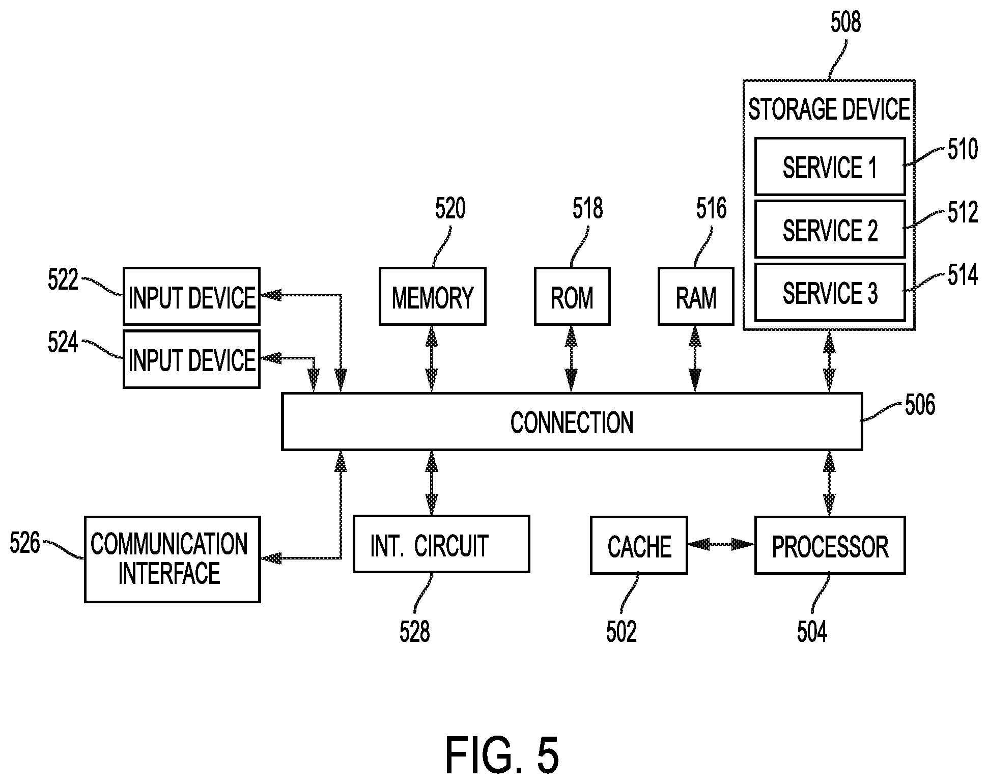
FIG. 5 illustrates an example system including various hardware computing components, according to an aspect of the present disclosure.
DETAILED DESCRIPTION
Various example embodiments of the disclosure are discussed in detail below. While specific implementations are discussed, it should be understood that this is done for illustration purposes only. A person skilled in the relevant art will recognize that other components and configurations may be used without parting from the spirit and scope of the disclosure. Thus, the following description and drawings are illustrative and are not to be construed as limiting. Numerous specific details are described to provide a thorough understanding of the disclosure. However, in certain instances, well-known or conventional details are not described in order to avoid obscuring the description. References to one or an embodiment in the present disclosure can be references to the same embodiment or any embodiment; and, such references mean at least one of the embodiments.
Reference to "one embodiment" or "an embodiment" means that a particular feature, structure, or characteristic described in connection with the embodiment is included in at least one embodiment of the disclosure. The appearances of the phrase "in one embodiment" in various places in the specification are not necessarily all referring to the same embodiment, nor are separate or alternative embodiments mutually exclusive of other embodiments. Moreover, various features are described which may be exhibited by some embodiments and not by others.
The terms used in this specification generally have their ordinary meanings in the art, within the context of the disclosure, and in the specific context where each term is used. Alternative language and synonyms may be used for any one or more of the terms discussed herein, and no special significance should be placed upon whether or not a term is elaborated or discussed herein. In some cases, synonyms for certain terms are provided. A recital of one or more synonyms does not exclude the use of other synonyms. The use of examples anywhere in this specification including examples of any terms discussed herein is illustrative only, and is not intended to further limit the scope and meaning of the disclosure or of any example term. Likewise, the disclosure is not limited to various embodiments given in this specification.
Without intent to limit the scope of the disclosure, examples of instruments, apparatus, methods and their related results according to the embodiments of the present disclosure are given below. Note that titles or subtitles may be used in the examples for convenience of a reader, which in no way should limit the scope of the disclosure. Unless otherwise defined, technical and scientific terms used herein have the meaning as commonly understood by one of ordinary skill in the art to which this disclosure pertains. In the case of conflict, the present document, including definitions will control.
Additional features and advantages of the disclosure will be set forth in the description which follows, and in part will be obvious from the description, or can be learned by practice of the herein disclosed principles. The features and advantages of the disclosure can be realized and obtained by means of the instruments and combinations particularly pointed out in the appended claims. These and other features of the disclosure will become more fully apparent from the following description and appended claims, or can be learned by the practice of the principles set forth herein.
As referenced herein, a Function Router can include a service that provides for registration and management of execution endpoints, FaaS services, functions, clients, locations, and routing rules on an account. The Function Router can receive requests for function execution from clients and dynamically route them to the `best` endpoint to execute that function based on defined rules.
An Execution Endpoint (EE) can include a compute-capable system that can run functions. Non-limiting examples can include computers, laptops, IoT devices, servers, switches (e.g., virtual switches and routers (vswitches/vrouters), mobile phones, kiosks, workstations, etc. EEs can be registered in the Function Router for use in executing functions. Execution endpoints can run various FaaS runtime environments and services.
A client can include a device and/or application seeking to execute a function on an Execution Endpoint. Non-limiting examples of a client can include a robot arm, mobile phone, hand scanner, application, printer, kiosk, etc.
A function can include a piece of code. The piece of code can represent, for example, an ephemeral, self-contained set of business logic. Serverless functions can be compared to stored procedures in that they do a specific thing, and are called and executed when needed, only to go back to being dormant (but ready) when execution completes.
A location can include a physical location (e.g., a building, a floor, etc.) and/or a logical location. A location can be associated with specific latitude and longitude coordinates. For example, a location can refer to specific latitude and longitude coordinates corresponding to the manufacturing floor where a robot resides or a conference room where an FaaS device is plugged in, or a region associated with an environment.
Function routing rules can include policies and controls around who, what, when, where, why, and/or how for function execution. The rules can include IT-defined guardrails that affect the entire system, and other rules specified by IT or a development team for a specific function. Example rules can include: Function A can run on any endpoint but Function B must only run on a private endpoint; or Function A can be called by any client in a specific location, but function B can only be called by specific clients in any location.
Overview
Disclosed are systems, methods, and computer-readable media for enabling traffic flow and data communication between network containers hosted on different physical hosts without performing a handshake process for establishing a communication channel therebetween.
In one aspect of the present disclosure, a method includes receiving, at a source switch, a request from a first network container on a source server to establish a data session with a second network container on a destination server; determining, by the source switch, a destination switch of the destination server based on the request; identifying, by the source switch, a pre-established communication tunnel between the source server and the destination server; generating, by the source switch, a data stream to be embedded in the pre-established communication tunnel, wherein a communication protocol associated with the request is different from a communication protocol used by the data stream for communicating data between the first and second network containers; receiving a data packet, at the source switch, to be sent to the destination container; mapping, by the source switch, the data packet to the data stream; and sending, by the source switch, the data packet to the destination server via the data stream over the communication tunnel.
In one aspect of the present disclosure, a device includes one or more network containers implemented thereon and a network switch configured that is configured to receive a request from a first network container of the one or more network containers on the server to establish a data session with a second network container on a destination server; determine a destination switch of the destination network based on the request; identify a communication tunnel between the server and the destination server; generate a data stream to be embedded in the communication tunnel for exchange of data packets between the first network container and the second network container, wherein a communication protocol associated with the request received from the first network container is different from a communication protocol used by the data stream for facilitating the exchange of data packets between the first and second network containers; receive a data packet from the first network container to be sent to the destination container; map the data packet to the data stream; and send the data packet to the destination server via the data stream over the communication tunnel.
In one aspect of the present disclosure, one or more non-transitory computer-readable medium have computer-readable instructions stored thereon, which when executed by one or more processors, cause the one or more processors to function as a virtual switch of a server to receive a request from a first network container on the server to establish a transfer control protocol (TCP) session with a second network container on a destination server; determine a destination switch of the destination network based on the request; identify a communication tunnel between the server and the destination server; generate a data stream to be embedded in the communication tunnel for exchange of data packets between the first network container and the second network container, wherein a communication used by the data stream for facilitating the exchange of data packets between the first and second network containers is different from a TCP protocol used for the TCP session; receive a TCP data packet from the first network container to be sent to the destination container; map the TCP data packet to the data stream; and transmit the TCP data packet to the destination server via the data stream over the communication tunnel.
DETAILED DESCRIPTION
The disclosed technology addresses the need in the art for reducing latency and CPU cycles used to setup connections between network containers and the large number of flows and states used for container networking in Network fabrics.
The disclosure begins with a description of example network environments and architectures which can be implemented for serverless computing and service function chaining, as illustrated in FIGS. 1A, 1B, and 2, is first disclosed herein.
FIG. 1A illustrates an example cloud computing architecture, according to one aspect of the present disclosure. FIG. 1A illustrates a diagram of an example cloud computing architecture 100 or simply architecture 100. Architecture 100 can include a cloud 102. Cloud 102 can include one or more private clouds, public clouds, and/or hybrid clouds. Moreover, cloud 102 can include cloud elements 104-114. Cloud elements 104-114 can include, for example, servers 104, virtual machines (VMs) 106, one or more software platforms 108, applications or services 110, software containers 112, and infrastructure nodes 114. The infrastructure nodes 114 can include various types of nodes, such as compute nodes, storage nodes, network nodes, management systems, etc.
Cloud 102 can provide various cloud computing services via cloud elements 104-114, such as software as a service (SaaS) (e.g., collaboration services, email services, enterprise resource planning services, content services, communication services, etc.), infrastructure as a service (IaaS) (e.g., security services, networking services, systems management services, etc.), platform as a service (PaaS) (e.g., web services, streaming services, application development services, etc.), function as a service (FaaS), and other types of services such as desktop as a service (DaaS), information technology management as a service (ITaaS), managed software as a service (MSaaS), mobile backend as a service (MBaaS), etc.
Client endpoints 116 can connect with cloud 102 to obtain one or more specific services from cloud 102. Client endpoints 116 can communicate with elements 104-114 via one or more public networks (e.g., Internet), private networks, and/or hybrid networks (e.g., virtual private network). Client endpoints 116 can include any device with networking capabilities, such as a laptop computer, a tablet computer, a server, a desktop computer, a smartphone, a network device (e.g., an access point, a router, a switch, etc.), a smart television, a smart car, a sensor, a GPS device, a game system, a smart wearable object (e.g., smartwatch, etc.), a consumer object (e.g., Internet refrigerator, smart lighting system, etc.), a city or transportation system (e.g., traffic control, toll collection system, etc.), an internet of things (IoT) device, a camera, a network printer, a transportation system (e.g., airplane, train, motorcycle, boat, etc.), or any smart or connected object (e.g., smart home, smart building, smart retail, smart glasses, etc.), and so forth.
FIG. 1B illustrates an example fog computing architecture, according to one aspect of the present disclosure. FIG. 1B illustrates a diagram of an example fog computing architecture 150. Fog computing architecture 150 can include cloud layer 154, which includes cloud 102 and any other cloud system or environment, and fog layer 156, which includes fog nodes 162. Client endpoints 116 can communicate with cloud layer 154 and/or fog layer 156. Architecture 150 can include one or more communication links 152 between cloud layer 154, fog layer 156, and client endpoints 116. Communications can flow up to cloud layer 154 and/or down to client endpoints 116.
Fog layer 156 or "the fog" provides the computation, storage and networking capabilities of traditional cloud networks, but closer to the endpoints. Fog 156 can thus extend cloud 102 to be closer to client endpoints 116. Fog nodes 162 can be the physical implementation of fog networks. Moreover, fog nodes 162 can provide local or regional services and/or connectivity to the client endpoints 116. As a result, traffic and/or data can be offloaded from cloud 102 to fog layer 156 (e.g., via fog nodes 162). Fog layer 156 can thus provide faster services and/or connectivity to client endpoints 116, with lower latency, as well as other advantages such as security benefits from keeping the data inside the local or regional network(s).
Fog nodes 162 can include any networked computing devices, such as servers, switches (e.g., vswitches/vrouters), routers, controllers, cameras, access points, kiosks, gateways, etc. Moreover, fog nodes 162 can be deployed anywhere with a network connection, such as a factory floor, a power pole, alongside a railway track, in a vehicle, on an oil rig, in an airport, on an aircraft, in a shopping center, in a hospital, in a park, in a parking garage, in a library, etc.
In some configurations, one or more fog nodes 162 can be deployed within fog instances 158, 160. Fog instances 158, 160 can be local or regional clouds or networks. For example, fog instances 158, 160 can be a regional cloud or data center, a local area network, a network of fog nodes 162, etc. In some configurations, one or more fog nodes 162 can be deployed within a network, or as standalone or individual nodes, for example. Moreover, one or more of fog nodes 162 can be interconnected with each other via links 164 in various topologies, including star, ring, mesh or hierarchical arrangements, for example.
In some cases, one or more fog nodes 162 can be mobile fog nodes. The mobile fog nodes can move to different geographic locations, logical locations or networks, and/or fog instances while maintaining connectivity with cloud layer 154 and/or endpoints 116. For example, a particular fog node can be placed in a vehicle, such as an aircraft or train, which can travel from one geographic location and/or logical location to a different geographic location and/or logical location. In this example, the particular fog node may connect to a particular physical and/or logical connection point with cloud 154 while located at the starting location and switch to a different physical and/or logical connection point with cloud 154 while located at the destination location. The particular fog node can thus move within particular clouds and/or fog instances and, therefore, serve endpoints from different locations at different times.
FIG. 2 illustrates a schematic diagram of an example network architecture, according to one aspect of the present disclosure. FIG. 2 illustrates example network architecture 200. In some examples, the architecture 200 can include a data center, which can support and/or host cloud 102. Moreover, architecture 200 includes a network fabric 212 with spines 202A, 202B, . . . , 202N (collectively "202") connected to leafs 204A, 204B, 204C, . . . , 204N (collectively "204") in network fabric 212. Spines 202 and leafs 204 can be Layer 2 and/or Layer 3 devices, such as vswitches or vrouters. For the sake of clarity, they will be referenced herein as spine switches 202 and leaf switches 204.
Spine switches 202 can connect to leaf switches 204 in fabric 212. Leaf switches 204 can include access ports (or non-fabric ports) and fabric ports. Fabric ports can provide uplinks to spine switches 202, while access ports can provide connectivity for devices, hosts, endpoints, VMs, or external networks to fabric 212.
Leaf switches 204 can reside at the boundary between fabric 212 and the tenant or customer space. Leaf switches 204 can route and/or bridge the tenant packets and apply network policies. In some cases, a leaf switch can perform one or more additional functions, such as implementing a mapping cache, sending packets to the proxy function when there is a miss in the cache, encapsulate packets, enforce ingress or egress policies, etc.
Moreover, leaf switches 204 can contain virtual switching and/or tunneling functionalities, such as a virtual tunnel endpoint (VTEP) function. Thus, leaf switches 204 can connect fabric 212 to an overlay (e.g., VXLAN network).
Network connectivity in fabric 212 can flow through leaf switches 204. Leaf switches 204 can provide servers, resources, endpoints, external networks, containers, or VMs access to fabric 212, and can connect leaf switches 204 to each other. Leaf switches 204 can connect applications and/or endpoint groups ("EPGs") to other resources inside or outside of fabric 212 as well as any external networks.
Endpoints 210A-E (collectively "210") can connect to fabric 212 via leaf switches 204. For example, endpoints 210A and 210B can connect directly to leaf switch 204A, which can connect endpoints 210A and 210B to fabric 212 and/or any other of leaf switches 204. Similarly, endpoint 210E can connect directly to leaf switch 204C, which can connect endpoint 210E to fabric 212 and/or any other of leaf switches 204. On the other hand, endpoints 210C and 210D can connect to leaf switch 204A and 204B via network 206. Moreover, wide area network (WAN) 208 can connect to leaf switches 204N.
Endpoints 210 can include any communication device or resource, such as a computer, a server, a cluster, a switch, a container, a VM, a virtual application, etc. In some cases, endpoints 210 can include a server or switch configured with a virtual tunnel endpoint functionality which connects an overlay network with fabric 212. For example, in some cases, endpoints 210 can represent hosts (e.g., servers) with virtual tunnel endpoint capabilities, and running virtual environments (e.g., hypervisor, virtual machine(s), containers, etc.). An overlay network associated with the endpoints 210 can host physical devices, such as servers; applications; EPGs; virtual segments; virtual workloads; etc. Likewise, endpoints 210 can also host virtual workloads and applications, which can connect with fabric 212 or any other device or network, including an external network.
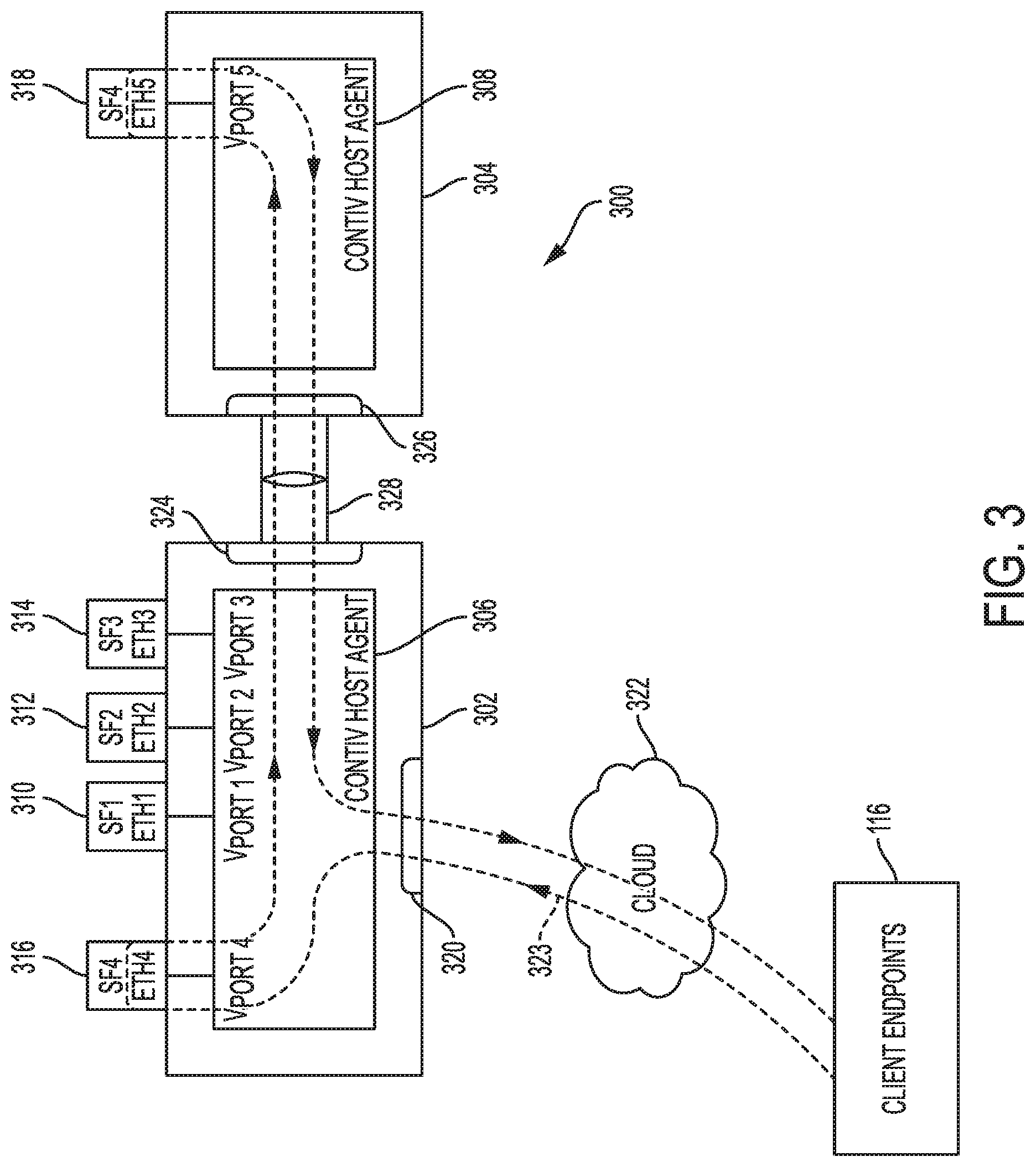
FIG. 3 illustrates an example structure of containers instantiated over two physical hosts, according to one aspect of the present disclosure.
Environment 300 includes two physical hosts 302 and 304 (which can be the same as two of servers 104 shown in and described with reference to FIG. 1A). Each one of physical hosts 302 and 304 can have a Contiv HostAgent operating thereon such as Contiv HostAgents 306 and 308. Contiv HostAgents 306 and 308 can deliver policy-based management of various service functions deployed/instantiated as containers on a corresponding physical host.
Physical host 302 can have one or more containers (network containers) instantiated thereon such as containers 310, 312, 314 and/or 316. A container may also be referred to as a Point of Delivery (pod). For example, each container 310, 312, 314 can provide one service function (SF) such as one of SF1, SF2 or SF3 on physical host 302. Furthermore, physical host 302 can have a service function forwarder (SFF) 316, provided by a separate container running on physical host 302 or alternatively provided by one of containers 310, 312, 314 providing SF1, SF2 and/or SF3 that can direct data traffic and tasks to different containers depending on the specific function to be performed. Each of containers 310, 213, 314,316 can interface with Contiv HostAgent 306 via a virtual port thereof (i.e., one of ETH0-ETH4) and corresponding virtual ports of Contiv HostAgent 306 (i.e., one of Vport1-Vport4). Similarly, physical host 304 can have a SF4 running on container 318. Container 318 can also act as a SFF in a similar manner as SFF running on container 316. Container 318 can interface with Contiv HostAgent 308 via a virtual port thereof (i.e., ETH5) and corresponding virtual port of Contiv HostAgent 308 (i.e., Vport5).
Physical host 302 may have a physical port 320 through which data from client end points such as client endpoints 116 of FIG. 1A are received via cloud 322. For example, cloud 322 can be cloud 102 of FIG. 1A or fog 156 of FIG. 1B. Incoming data may be sent to container 316 (SFF) to be directed to one or more of containers 310, 312, 314 and/or 318 for servicing. An example data flow 323 through physical hosts 302/304 and containers 310, 312, 314, 316, 318 is shown in FIG. 3. However, inventive concepts are not limited thereto.
Furthermore, physical host 302 can have a switch 324 which may be a physical or virtual switch (vswitch) for establishing connection with other network components such as physical host 304 and container 318 running thereon. Similarly, physical host 304 can have a switch 326 which may be a physical or a virtual switch (vswitch) for establishing connection with other network components such as physical host 302 and containers 310, 312, 314, 316 running thereon.
In one example, SF1-SF4 provide a firewall service to one or more customers such as client endpoints 116 of FIG. 1A. Accordingly, in the example of FIG. 3, different service functions are instantiated as different ones of containers 310, 312, 314 and 318 on two different physical hosts, namely physical hosts 302 and 304. This distribution of service functions over different physical hosts can be due to, for example, high demand for particular service function being provided by a container on a given physical host and can be done for purposes of load balancing.
Accordingly, one of more of containers 310, 312, 314 on physical host 302 may attempt to establish a connection with container 318 on physical host 304. As briefly mentioned above, data traffic between such containers is usually carried via Secure Socket Layer (SSL)/Transport Layer Security (TSL) encoded traffic on top of Hyper Text Transfer Protocol (HTTP)1/2 layers. This transport requires a handshake process to be completed between containers, which consumes a significant number of CPU cycles. Considering highly meshed applications and services, a number of requested and active Transport Control Protocol (TCP) connections between containers grows with a square of the number of containers (e.g., by (N(N-1)/2, with N being the number of containers). Furthermore, in such highly meshed applications and multiple containers implementing such applications, the number of active flows increases. This increase is problematic for some Network Fabric elements that cannot scale with the increase of number of flows such as Natural Address Translation (NAT), Load Balancing, Reflexive Access Lists (ACLs) elements.
Hereinafter a process will be described for establishing a data communication session between network containers without performing the handshake process. This will be further described below with reference to FIG. 4.
For the functionalities, which will be described with reference to FIG. 4, the following assumptions can be taken into consideration: First, a server, physical or virtual such as physical host 302 or 304, has one virtual switch/router (vswitches 324 or 326, respectively) and has at least one IPv4 or IPv6 address. Second, a network container has at least one IPv4 or IPv6 address associated therewith. Third, when a server/physical host joins a cluster of servers/physical hosts, the joining server/physical host establishes an HTTP2 tunnel over a SSL connection to every other server in the cluster, such as tunnel 328 between physical hosts 302 and 304. Another example communication tunnel over a SSL connection is a Quick User Datagram Protocol (UDP) Internet Connection (QUIC) tunnel. While HTTP2 and QUIC are provided as example protocols for establishing communication tunnels over a SSL connection, the present disclosure is not limited thereto and any other known, or to be developed, applicable communication protocol may be used.
While FIG. 3 illustrates only two physical hosts, as the number of physical hosts increase, it is easy to see that any two physical host can be connected via a communication tunnel such as tunnel 328, thus resulting in a mesh of tunnels, each having one or more data streams embedded therein for establishing a data session between containers residing on the two corresponding physical hosts.
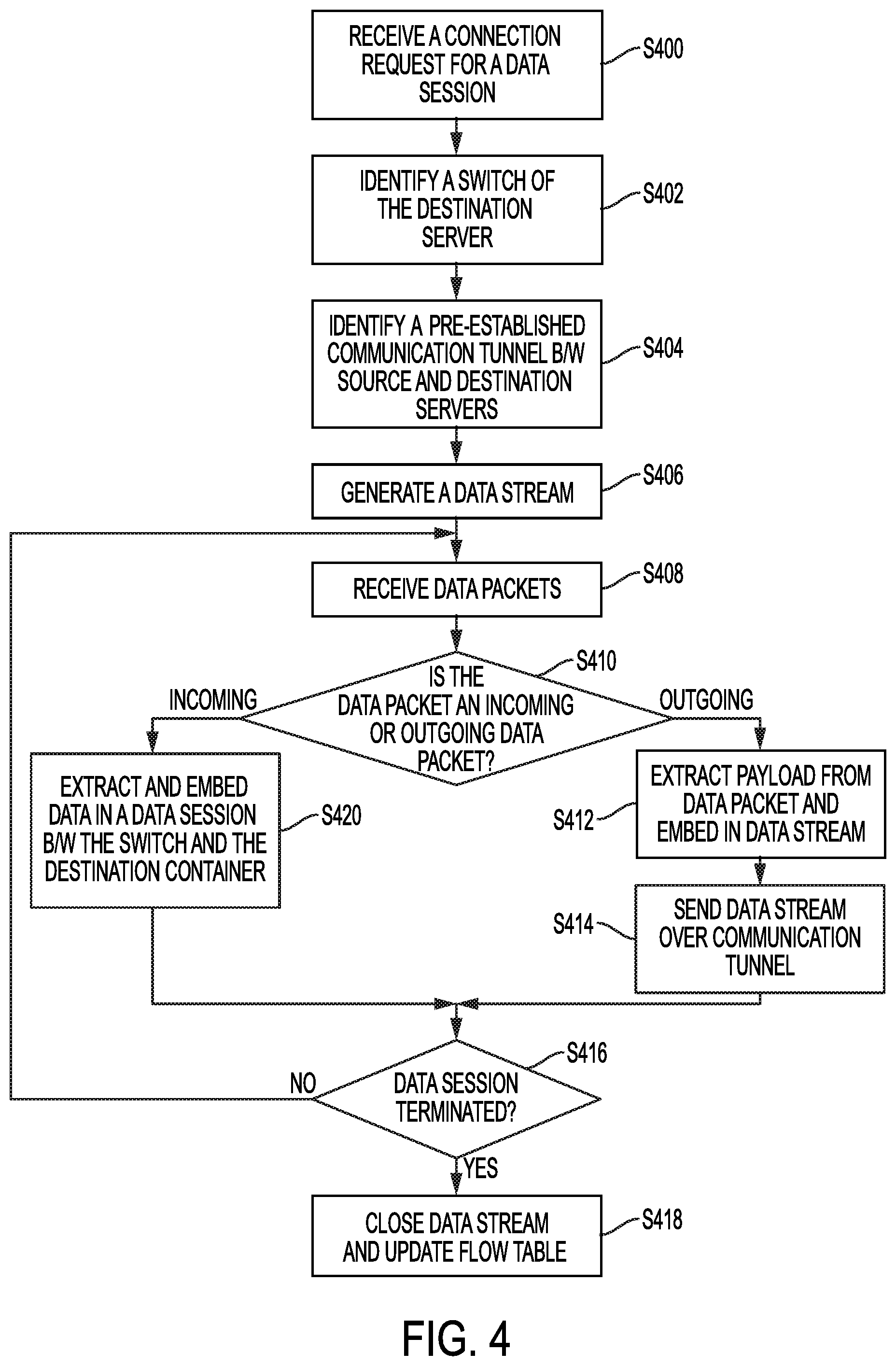
With the above assumptions, the disclosure now turns to FIG. 4. FIG. 4 is a method of container networking, according to some aspects of the present disclosure. FIG. 4 will be described from the perspective of switch 324 of physical host 302. However, it is readily ascertainable that the method of FIG. 4 can be implemented by switch 326 of physical host 304 or a switch of any other network connected server/physical host providing resources for running container-based services and applications. Furthermore, in describing FIG. 4, switch 324 may be referred as the source switch, switch 326 may be referred to as the destination switch, physical host 302 may be referred to as the source server and physical host 304 may be referred to as the destination server.
At S400, switch 324 receives a connection request from a first container (e.g., one of containers 310, 312, 314, 316 hosted on physical host 302) to establish a data session with a second container (e.g., container 318 hosted on physical host 304). This connection and the requested data session can also be referred to as a container-to-container connection request and a container-to-container data session. The requested data session may be a TCP session to the second container for exchanging data.
In one example, as part of the connection request, switch 324 receives a TCP synchronization (TCP SYN) packet from the first container. TCP SYN packet can include various information including, but not limited to, an IP address of container 318 (second container), which can be a virtual or actual IP address assigned to container 318. This may be referred to as the destination IP address.
In one example, if the destination IP address is a virtual IP address, switch 324 may assign an actual (physical) IP address of the destination container 318 thereto using any known or to be developed selection algorithm (e.g., cluster IP mode implemented in Kubernetes or Contiv-VPP).
In one example, and upon receiving the connection request, switch 324 can establish a TCP session between first network container, from which the connection request is received at S400 and switch 324.
At S402, switch 324 identifies a switch (a destination switch) of the destination server based on the destination IP address. Included in the TCP SYN packet. This can be switch 326 of physical host 304 in FIG. 3.
In one example, each of the source switch (e.g., switch 324) and the destination switch (e.g., switch 326) can be a virtual switch/virtual router or a physical switch/physical router.
At S404 and after identifying the destination server and destination switch at S402, switch 324 identifies a pre-established/existing communication tunnel between the source and destination servers (e.g., the HTTP2 tunnel 328 of FIG. 3 established between physical host 302 and physical host 304).
At S406, switch 324 generates a data stream to be embedded in the communication tunnel for communicating data packets (e.g., TCP data packets) received from the source container to be sent to the destination. The data stream may be an HTTP2 stream in the HTTP2 tunnel. In one example, switch 324 generates the HTTP2 stream by creating a packet using a ":connect" method in a header field of the packet and including the destination IP address and ports (e.g., virtual ports connection Contiv HostAgent 306 to the source container (e.g., one of containers 310, 312, 314, 316), which can be extracted from the TCP SYN packet.
In another example and when a QUIC stream in a QUIC tunnel is used instead of HTTP2, appropriate QUIC headers and methods may be utilized to generate the data stream.
Accordingly, the communication protocol used by the data stream for sending and receiving data between physical hosts 302 and 304 is different from the communication protocol originally requested by the source container at S400 (e.g., HTTP2 v. TCP).
In one example, switch 324 (the source switch) has a flow table created for mapping 5-tuple of container to container TCP connection requested at S400 to an identifier of the HTTP2 stream.
Having established the HTTP2 stream, at S408, switch 324 receives data packets from the source container (e.g., one of containers 310, 312, 314, 316).
In one example, at S408, the data packet received by switch 324 can be an outgoing TCP data packet originating from the source container and destined for the destination container, as described above. In the alternative, the data packet received by switch 324 at S408 can be an incoming HTTP2 Data (or alternatively, QUIC data), which was originally sent by another container (e.g., container 318) hosted on a different server (e.g., physical host 304) as a TCP data packet but converted and transmitted by the switch (e.g., switch 326) of the different server into HTTP2 data before transmission thereof to switch 324 and ultimately to the target container (e.g., one of containers 310, 312, 314, 316 hosted on physical host 302).
Therefore, at S410, switch 324 determines if a received data packet is an outgoing packet or an incoming packet. If at S410, switch 324 determines that the packet is an outgoing TCP data packet, then at S412, switch 324 extracts the payload of the TCP data packet received at S408 and embeds the same into data packets portion of the HTTP2 stream.
In one example and at any given point, switch 324 may have multiple HTTP2 sessions created, all of which can be multiplexed onto the HTTP2 tunnel destined for the destination server and containers hosted thereon. Therefore, using the flow table, switch 324 can manage the incoming/outgoing data packets and map them to the correct HTTP2 streams.
Thereafter, at S414, switch 324 sends the HTTP2 stream over the HTTP2 tunnel to the destination switch (e.g., switch 326). By using the HTTP2 session over an existing HTTP2 tunnel, the need for establishing a TCP connection between the source and destination containers and the underlying handshake process is eliminated.
At S416, switch 324 determines if the data session (e.g., the TCP session) has been terminated. Switch 324 may determine the termination of the TCP session by receiving a notification of termination from the source container.
If at S416, switch 324 determines that the TCP session is still active/alive (NO at S416), the process reverts back to S408 and switch 324 continues to receive TCP packets. However, if at S416, switch 324 determines that the TCP session is terminated, then at S418, switch 324 closes the data stream (HTTP2 stream) and updates the flow table accordingly (e.g., removes the corresponding TCP connection-HTTP2 stream mapping entry from the flow table).
Referring back to S410, if switch 324 determines that the received packet is an incoming HTTP2 data packet, then at S420, switch 324 extracts the data from the received HTTP2 data packet and embeds the same into an existing TCP data packet to be sent to the target container (e.g., one of containers 310, 312, 314, 316) for which a TCP session with switch 324 is active. Thereafter, the process reverts back to S416 and S416 and S418 are repeated.
The process of FIG. 4 can provide the following advantages. First, the number of active and open TCP sessions grows with the square of the number of servers/physical hosts in a cluster of connected servers and not the square of the number of containers (there can be multiple containers on a single physical host). Given that containers are spawned very frequently to provide services, persistent connections between the containers are no longer needed but instead existing persistent connection between their physical hosts to create "as-needed" container-to-container connections as streams embedded in an HTTP2 tunnel between physical hosts.
Second, connections between source and destination containers are no longer visible at the physical infrastructure since they are tunneled through HTTP2 streams established on-demand. Furthermore, TCP connections between containers and hence the network resource consuming handshake process thereof are also eliminated, which reduces the number of flows in the network Fabric generated as a result of the large number of containers that implement highly meshed applications
The disclosure now turns to FIG. 5, which illustrates an example device. These example device can function as any one of network components such as physical host 302 and/or 304 of FIG. 3 to enable instantiation of containers that in turn provide service functions to end client devices and perform the above described method of FIG. 4.
FIG. 5 illustrates an example system including various hardware computing components, according to an aspect of the present disclosure. The more appropriate embodiment will be apparent to those of ordinary skill in the art when practicing the present technology. Persons of ordinary skill in the art will also readily appreciate that other system embodiments are possible.
FIG. 5 illustrates a system bus computing system architecture 500 wherein the components of the system are in electrical communication with each other using a connection 506. Exemplary system 500 includes a processing unit (CPU or processor) 504 and a system connection 506 that couples various system components including the system memory 520, such as read only memory (ROM) 518 and random access memory (RAM) 516, to the processor 504. The system 500 can include a cache of high-speed memory connected directly with, in close proximity to, or integrated as part of the processor 504. The system 500 can copy data from the memory 520 and/or the storage device 508 to the cache 502 for quick access by the processor 504. In this way, the cache can provide a performance boost that avoids processor 504 delays while waiting for data. These and other modules can control or be configured to control the processor 504 to perform various actions. Other system memory 520 may be available for use as well. The memory 520 can include multiple different types of memory with different performance characteristics. The processor 504 can include any general purpose processor and a service component, such as service 1 510, service 2 512, and service 3 514 stored in storage device 508, configured to control the processor 504 as well as a special-purpose processor where software instructions are incorporated into the actual processor design. The processor 504 may essentially be a completely self-contained computing system, containing multiple cores or processors, a bus, memory controller, cache, etc. A multi-core processor may be symmetric or asymmetric.
To enable user interaction with the computing device 500, an input device 522 can represent any number of input mechanisms, such as a microphone for speech, a touch-sensitive screen for gesture or graphical input, keyboard, mouse, motion input, speech and so forth. An output device 524 can also be one or more of a number of output mechanisms known to those of skill in the art. In some instances, multimodal systems can enable a user to provide multiple types of input to communicate with the computing device 500. The communications interface 526 can generally govern and manage the user input and system output. There is no restriction on operating on any particular hardware arrangement and therefore the basic features here may easily be substituted for improved hardware or firmware arrangements as they are developed.
Storage device 508 is a non-volatile memory and can be a hard disk or other types of computer readable media which can store data that are accessible by a computer, such as magnetic cassettes, flash memory cards, solid state memory devices, digital versatile disks, cartridges, random access memories (RAMs) 516, read only memory (ROM) 518, and hybrids thereof.
The system 500 can include an integrated circuit 528, such as an application-specific integrated circuit (ASIC) configured to perform various operations. The integrated circuit 528 can be coupled with the connection 506 in order to communicate with other components in the system 500.
The storage device 508 can include software services 510, 512, 514 for controlling the processor 504. Other hardware or software modules are contemplated. The storage device 508 can be connected to the system connection 506. In one aspect, a hardware module that performs a particular function can include the software component stored in a computer-readable medium in connection with the necessary hardware components, such as the processor 504, connection 506, output device 524, and so forth, to carry out the function.
For clarity of explanation, in some instances the present technology may be presented as including individual functional blocks including functional blocks comprising devices, device components, steps or routines in a method embodied in software, or combinations of hardware and software.
In some example embodiments the computer-readable storage devices, mediums, and memories can include a cable or wireless signal containing a bit stream and the like. However, when mentioned, non-transitory computer-readable storage media expressly exclude media such as energy, carrier signals, electromagnetic waves, and signals per se.
Methods according to the above-described examples can be implemented using computer-executable instructions that are stored or otherwise available from computer readable media. Such instructions can comprise, for example, instructions and data which cause or otherwise configure a general purpose computer, special purpose computer, or special purpose processing device to perform a certain function or group of functions. Portions of computer resources used can be accessible over a network. The computer executable instructions may be, for example, binaries, intermediate format instructions such as assembly language, firmware, or source code. Examples of computer-readable media that may be used to store instructions, information used, and/or information created during methods according to described examples include magnetic or optical disks, flash memory, USB devices provided with non-volatile memory, networked storage devices, and so on.
Devices implementing methods according to these disclosures can comprise hardware, firmware and/or software, and can take any of a variety of form factors. Typical examples of such form factors include laptops, smart phones, small form factor personal computers, personal digital assistants, rackmount devices, standalone devices, and so on. Functionality described herein also can be embodied in peripherals or add-in cards. Such functionality can also be implemented on a circuit board among different chips or different processes executing in a single device, by way of further example.
The instructions, media for conveying such instructions, computing resources for executing them, and other structures for supporting such computing resources are means for providing the functions described in these disclosures.
Although a variety of examples and other information was used to explain aspects within the scope of the appended claims, no limitation of the claims should be implied based on particular features or arrangements in such examples, as one of ordinary skill would be able to use these examples to derive a wide variety of implementations. Further and although some subject matter may have been described in language specific to examples of structural features and/or method steps, it is to be understood that the subject matter defined in the appended claims is not necessarily limited to these described features or acts. For example, such functionality can be distributed differently or performed in components other than those identified herein. Rather, the described features and steps are disclosed as examples of components of systems and methods within the scope of the appended claims.
Claim language reciting "at least one of" a set indicates that one member of the set or multiple members of the set satisfy the claim. For example, claim language reciting "at least one of A and B" means A, B, or A and B.
* * * * *
References
-
docs.cask.co/cdap/3.6.0/en/developers-manual/building-blocks/flows-flowlets/index.html
-
blog.twinstrata.com/2012/07/10//5-benefits-of-a-storage-gateway-in-the-cloud
-
lbarb.co.uk/whats-next
-
cisco.com/en/US/prod/collateral/switches/ps9441/ps9902/white_paper_c11-558242.pdf
-
css-cloud.com/platform/enterprise-cloud-gateway.php
-
download.openvz.org/doc/openvz-intro.pdf
-
lerach.cz/en/products/golem
-
flexiant.com
-
nielsen-admosphere.eu/products-and-services/simmetry-audience-measurement-technology
-
nielsen.com/us/en/solutions/measurement/television.html
-
docs.openstack.org/nova/latest/user/filter-scheduler.html
-
en.wikipedia.org/w/index.php?title=Filter_%28software%29&oldid=594544359
-
D00000
D00001
D00002
D00003
D00004
D00005
D00006
XML
uspto.report is an independent third-party trademark research tool that is not affiliated, endorsed, or sponsored by the United States Patent and Trademark Office (USPTO) or any other governmental organization. The information provided by uspto.report is based on publicly available data at the time of writing and is intended for informational purposes only.
While we strive to provide accurate and up-to-date information, we do not guarantee the accuracy, completeness, reliability, or suitability of the information displayed on this site. The use of this site is at your own risk. Any reliance you place on such information is therefore strictly at your own risk.
All official trademark data, including owner information, should be verified by visiting the official USPTO website at www.uspto.gov. This site is not intended to replace professional legal advice and should not be used as a substitute for consulting with a legal professional who is knowledgeable about trademark law.