Modular box assembly
Sollie , et al. January 26, 2
U.S. patent number 10,899,531 [Application Number 16/552,277] was granted by the patent office on 2021-01-26 for modular box assembly. This patent grant is currently assigned to Pratt Retail Specialties, LLC. The grantee listed for this patent is Pratt Retail Specialties, LLC. Invention is credited to Shifeng Chen, Greg Sollie, Jamie Waitermire.


View All Diagrams
| United States Patent | 10,899,531 |
| Sollie , et al. | January 26, 2021 |
Modular box assembly
Abstract
A modular box assembly includes a box having a top end, an opposed bottom end, and side panels extending from the top end to the bottom end. A bottom panel is disposed at the bottom end such that the side panels and the bottom panel define a box cavity and the top end defines a box opening. A shoulder is attached to two side panel and extends inward from the side panels into the box cavity, wherein each shoulder is spaced from the top end a predetermined distance. A box top covers the box opening, the box top being selectively movable about and between a closed position and an open position. In the closed position, the top panel engages the shoulders to support the top panel, and in the closed position an upper surface of the top panel is substantially flush with the top end of the box.
| Inventors: | Sollie; Greg (Sharpsburg, GA), Waitermire; Jamie (Peachtree City, GA), Chen; Shifeng (Newport News, GA) | ||||||||||
|---|---|---|---|---|---|---|---|---|---|---|---|
| Applicant: |
|
||||||||||
| Assignee: | Pratt Retail Specialties, LLC
(Conyers, GA) |
||||||||||
| Appl. No.: | 16/552,277 | ||||||||||
| Filed: | August 27, 2019 |
Prior Publication Data
| Document Identifier | Publication Date | |
|---|---|---|
| US 20190382186 A1 | Dec 19, 2019 | |
Related U.S. Patent Documents
| Application Number | Filing Date | Patent Number | Issue Date | ||
|---|---|---|---|---|---|
| 15845545 | Dec 18, 2017 | 10507968 | |||
| Current U.S. Class: | 1/1 |
| Current CPC Class: | B65D 5/48012 (20130101); F25D 3/14 (20130101); B65D 81/3862 (20130101); B65D 5/46016 (20130101); B65D 81/3858 (20130101); B65D 5/4295 (20130101); B65D 5/3678 (20130101); B65D 5/46072 (20130101); F25D 2303/0844 (20130101) |
| Current International Class: | B65D 81/38 (20060101); B65D 5/46 (20060101); F25D 3/14 (20060101); B65D 5/48 (20060101); B65D 5/42 (20060101); B65D 5/36 (20060101) |
| Field of Search: | ;220/592.01-592.28 ;229/108,112,113,114,117.01,190,117.05 |
References Cited [Referenced By]
U.S. Patent Documents
| 265985 | October 1882 | Seabury |
| 1527167 | February 1925 | Birdseye |
| 1677565 | July 1928 | Oppenheim |
| 1682410 | August 1928 | Oppenheim |
| 1747980 | February 1930 | Kondolf |
| 1753813 | April 1930 | Washburn |
| 1868996 | July 1932 | Sharp |
| 1896393 | February 1933 | Devine |
| 1899892 | February 1933 | D'Este et al. |
| 1930680 | October 1933 | Hinton |
| 1935923 | November 1933 | Thoke |
| 1937263 | November 1933 | Bubb |
| 1942917 | January 1934 | D'Este et al. |
| 1954013 | April 1934 | Lilienfield |
| 2018519 | October 1935 | Hall |
| 2070747 | February 1937 | Ostrom |
| 2116513 | May 1938 | Frankenstein |
| 2148454 | February 1939 | Gerard |
| 2165327 | July 1939 | Zalkind |
| 2289060 | July 1942 | Merkle |
| 2293361 | August 1942 | Roberts |
| 2360806 | October 1944 | Van Rosen |
| 2386905 | October 1945 | Meitzen |
| 2389601 | November 1945 | De Witt |
| 2554004 | May 1951 | Bergstein |
| 2632311 | March 1953 | Sullivan |
| 2650016 | August 1953 | McMillan |
| 2753102 | July 1956 | Paige |
| 2899103 | August 1959 | Ebert |
| 2927720 | March 1960 | Adams |
| 2987239 | June 1961 | Atwood |
| 3029008 | April 1962 | Membrino |
| 3031121 | April 1962 | Chase |
| 3065895 | November 1962 | Lipschutz |
| 3096879 | July 1963 | Schumacher |
| 3097782 | July 1963 | Koropatkin et al. |
| 3182913 | May 1965 | Brian |
| 3193176 | July 1965 | Gullickson |
| 3222843 | December 1965 | Schneider |
| 3236206 | February 1966 | Willinger |
| 3282411 | November 1966 | Jardine |
| 3286825 | November 1966 | Laas |
| 3335941 | August 1967 | Gatward |
| 3371462 | March 1968 | Nordkvist et al. |
| 3375934 | April 1968 | Bates |
| 3420363 | January 1969 | Blickensderfer |
| 3435736 | April 1969 | Reiche |
| 3503550 | March 1970 | Main et al. |
| 3551945 | January 1971 | Eyberg et al. |
| 3670948 | June 1972 | Berg |
| 3703383 | November 1972 | Kuchenbecker |
| 3734336 | May 1973 | Rankow et al. |
| 3747743 | July 1973 | Hoffman, Jr. |
| 3749299 | July 1973 | Ingle |
| 3836044 | September 1974 | Tilp et al. |
| 3843038 | October 1974 | Sax |
| 3880341 | April 1975 | Bamburg et al. |
| 3887743 | June 1975 | Lane |
| 3890762 | June 1975 | Ernst et al. |
| 3980005 | September 1976 | Buonaiuto |
| 4030227 | June 1977 | Oftedahl |
| 4050264 | September 1977 | Tanaka |
| 4068779 | January 1978 | Canfield |
| 4091852 | May 1978 | Jordan et al. |
| 4169540 | October 1979 | Larsson et al. |
| 4211267 | July 1980 | Skovgaard |
| 4213310 | July 1980 | Buss |
| 4335844 | June 1982 | Egli |
| 4342416 | August 1982 | Philips |
| 4380314 | April 1983 | Langston, Jr. et al. |
| 4396144 | August 1983 | Gutierrez et al. |
| 4418864 | December 1983 | Neilsen |
| 4488623 | December 1984 | Linnell, II et al. |
| 4509645 | April 1985 | Hotta |
| 4679242 | July 1987 | Brockhaus |
| 4682708 | July 1987 | Pool |
| 4819793 | April 1989 | Willard et al. |
| 4828133 | May 1989 | Hougendobler |
| 4830282 | May 1989 | Knight, Jr. |
| 4889252 | December 1989 | Rockom et al. |
| 4930903 | June 1990 | Mahoney |
| 4989780 | February 1991 | Foote et al. |
| 5016813 | May 1991 | Simons |
| 5020481 | June 1991 | Nelson |
| 5062527 | November 1991 | Westerman |
| 5094547 | March 1992 | Graham |
| 5102004 | April 1992 | Hollander et al. |
| 5154309 | October 1992 | Wischusen, III et al. |
| 5158371 | October 1992 | Moravek |
| 5165583 | November 1992 | Kouwenberg |
| 5185904 | February 1993 | Rogers et al. |
| 5263339 | November 1993 | Evans |
| 5358757 | October 1994 | Robinette et al. |
| 5372429 | December 1994 | Beaver, Jr. et al. |
| 5417342 | May 1995 | Hutchison |
| 5418031 | May 1995 | English |
| 5441170 | August 1995 | Bane, III |
| 5454471 | October 1995 | Norvell |
| 5491186 | February 1996 | Kean et al. |
| 5493874 | February 1996 | Landgrebe |
| 5499473 | March 1996 | Ramberg |
| 5505810 | April 1996 | Kirby et al. |
| 5511667 | April 1996 | Carder |
| 5512345 | April 1996 | Tsutsumi et al. |
| 5516580 | May 1996 | Frenette et al. |
| 5562228 | October 1996 | Ericson |
| 5573119 | November 1996 | Luray |
| 5596880 | January 1997 | Welker et al. |
| 5613610 | March 1997 | Bradford |
| 5615795 | April 1997 | Tipps |
| 5638978 | June 1997 | Cadiente |
| 5775576 | July 1998 | Stone |
| 5842571 | December 1998 | Rausch |
| 5906290 | May 1999 | Haberkorn |
| 5996366 | December 1999 | Renard |
| 6003719 | December 1999 | Steward, III |
| 6041958 | March 2000 | Tremelo |
| 6050412 | April 2000 | Clough et al. |
| 6138902 | October 2000 | Welch |
| 6164526 | December 2000 | Dalvey |
| 6168040 | January 2001 | Sautner et al. |
| 6220473 | April 2001 | Lehman et al. |
| 6223551 | May 2001 | Mitchell |
| 6238091 | May 2001 | Mogil |
| 6244458 | June 2001 | Frysinger et al. |
| 6247328 | June 2001 | Mogil |
| 6295830 | October 2001 | Newman |
| 6295860 | October 2001 | Sakairi et al. |
| 6308850 | October 2001 | Coom et al. |
| 6325281 | December 2001 | Grogan |
| 6443309 | September 2002 | Becker |
| 6453682 | September 2002 | Jennings et al. |
| 6478268 | November 2002 | Bidwell et al. |
| 6510705 | January 2003 | Jackson |
| 6582124 | June 2003 | Mogil |
| 6618868 | September 2003 | Minnick |
| 6688133 | February 2004 | Donefrio |
| 6725783 | April 2004 | Sekino |
| 6726017 | April 2004 | Maresh et al. |
| 6736309 | May 2004 | Westerman et al. |
| 6771183 | August 2004 | Hunter |
| 6821019 | November 2004 | Mogil |
| 6837420 | January 2005 | Westerman et al. |
| 6868982 | March 2005 | Gordon |
| 6875486 | April 2005 | Miller |
| 6899229 | May 2005 | Dennison et al. |
| 6910582 | June 2005 | Lantz |
| 6971539 | December 2005 | Abbe |
| 7000962 | February 2006 | Le |
| 7019271 | March 2006 | Wnek et al. |
| 7094192 | August 2006 | Schoenberger et al. |
| 7140773 | November 2006 | Becker et al. |
| 7225632 | June 2007 | Derifield |
| 7225970 | June 2007 | Philips |
| 7229677 | June 2007 | Miller |
| 7264147 | September 2007 | Benson et al. |
| 7392931 | July 2008 | Issler |
| 7452316 | November 2008 | Cals et al. |
| D582676 | December 2008 | Rothschild |
| 7597209 | October 2009 | Rothschild et al. |
| 7607563 | October 2009 | Hanna et al. |
| 7677406 | March 2010 | Maxson |
| 7681405 | March 2010 | Williams |
| 7784301 | August 2010 | Sasaki et al. |
| 7807773 | October 2010 | Matsuoka et al. |
| 7841512 | November 2010 | Westerman et al. |
| 7845508 | December 2010 | Rothschild et al. |
| 7870992 | January 2011 | Schille et al. |
| 7909806 | March 2011 | Goodman et al. |
| 7971720 | July 2011 | Minkler |
| 8118177 | February 2012 | Drapela et al. |
| 8343024 | January 2013 | Costanzo, Jr. |
| 8365943 | February 2013 | Bentley |
| 8465404 | June 2013 | Hadley |
| 8579183 | November 2013 | Belfort et al. |
| 8596520 | December 2013 | Scott |
| 8613202 | December 2013 | Williams |
| 8651593 | February 2014 | Bezich et al. |
| 8763811 | July 2014 | Lantz |
| 8763886 | July 2014 | Hall |
| 8795470 | August 2014 | Henderson et al. |
| 8919082 | December 2014 | Cataldo |
| 8960528 | February 2015 | Sadlier |
| 9272475 | March 2016 | Ranade et al. |
| 9290313 | March 2016 | De Lesseux et al. |
| 9322136 | April 2016 | Ostendorf et al. |
| D758182 | June 2016 | Sponselee |
| 9408445 | August 2016 | Mogil et al. |
| 9429350 | August 2016 | Chapman, Jr. |
| 9499294 | November 2016 | Costanzo, Jr. |
| 9550618 | January 2017 | Jobe |
| 9605382 | March 2017 | Virtanen |
| 9611067 | April 2017 | Collison |
| 9635916 | May 2017 | Bezich et al. |
| 9701437 | July 2017 | Bugas et al. |
| 9738420 | August 2017 | Miller |
| 9738432 | August 2017 | Petrucci et al. |
| 9834366 | December 2017 | Giuliani |
| 9908680 | March 2018 | Shi et al. |
| 9908684 | March 2018 | Collison |
| 9920517 | March 2018 | Sollie et al. |
| 9950830 | April 2018 | De Lesseux et al. |
| 9981797 | May 2018 | Aksan et al. |
| 10046901 | August 2018 | Jobe |
| 10094126 | October 2018 | Collison et al. |
| 10112756 | October 2018 | Menzel, Jr. |
| 10226909 | March 2019 | Frem et al. |
| 10266332 | April 2019 | Aksan et al. |
| 10357936 | July 2019 | Vincent et al. |
| 10442600 | October 2019 | Waltermire et al. |
| 10507968 | December 2019 | Sollie et al. |
| 10551110 | February 2020 | Waltermire et al. |
| 10583977 | March 2020 | Collison et al. |
| 10800595 | October 2020 | Waltermire et al. |
| 2001/0010312 | August 2001 | Mogil |
| 2002/0020188 | February 2002 | Sharon et al. |
| 2002/0162767 | November 2002 | Ohtsubo |
| 2003/0145561 | August 2003 | Cals et al. |
| 2004/0004111 | January 2004 | Cardinale |
| 2004/0031842 | February 2004 | Westerman et al. |
| 2004/0079794 | April 2004 | Mayer |
| 2005/0109655 | May 2005 | Vershum et al. |
| 2005/0189404 | September 2005 | Xiaohai et al. |
| 2005/0214512 | September 2005 | Fascio |
| 2005/0224501 | October 2005 | Folkert et al. |
| 2005/0279963 | December 2005 | Church et al. |
| 2006/0053828 | March 2006 | Shallman et al. |
| 2006/0078720 | April 2006 | Toas et al. |
| 2006/0096978 | May 2006 | Lafferty et al. |
| 2006/0193541 | August 2006 | Norcom |
| 2007/0000932 | January 2007 | Cron et al. |
| 2007/0000983 | January 2007 | Spurrell et al. |
| 2007/0051782 | March 2007 | Lantz |
| 2007/0193298 | August 2007 | Derifield |
| 2007/0209307 | September 2007 | Andersen |
| 2007/0257040 | November 2007 | Price, Jr. et al. |
| 2008/0095959 | April 2008 | Warner et al. |
| 2008/0135564 | June 2008 | Romero |
| 2008/0173703 | July 2008 | Westerman et al. |
| 2008/0190940 | August 2008 | Scott |
| 2008/0203090 | August 2008 | Dickinson |
| 2008/0289302 | November 2008 | Vulpitta |
| 2008/0296356 | December 2008 | Hatcher et al. |
| 2008/0308616 | December 2008 | Phung |
| 2008/0314794 | December 2008 | Bowman |
| 2009/0034883 | February 2009 | Giuliani |
| 2009/0114311 | May 2009 | McDowell |
| 2009/0193765 | August 2009 | Lantz |
| 2009/0214142 | August 2009 | Bossel et al. |
| 2009/0283578 | November 2009 | Miller |
| 2009/0288791 | November 2009 | Hammer et al. |
| 2010/0001056 | January 2010 | Chandaria |
| 2010/0006630 | January 2010 | Humphries et al. |
| 2010/0062921 | March 2010 | Veiseh |
| 2010/0072105 | March 2010 | Glaser et al. |
| 2010/0139878 | June 2010 | Clemente |
| 2010/0151164 | June 2010 | Grant et al. |
| 2010/0258574 | October 2010 | Bentley |
| 2010/0282827 | November 2010 | Padovani |
| 2010/0284634 | November 2010 | Hadley |
| 2010/0314397 | December 2010 | Williams et al. |
| 2010/0314437 | December 2010 | Dowd |
| 2011/0042449 | February 2011 | Copenhaver et al. |
| 2011/0100868 | May 2011 | Lantz |
| 2011/0114513 | May 2011 | Miller |
| 2011/0235950 | September 2011 | Lin |
| 2011/0284556 | November 2011 | Palmer et al. |
| 2011/0311758 | December 2011 | Burns et al. |
| 2011/0317944 | December 2011 | Liu |
| 2012/0031957 | February 2012 | Whitaker |
| 2012/0074823 | March 2012 | Bezich et al. |
| 2012/0145568 | June 2012 | Collison et al. |
| 2012/0243808 | September 2012 | De Lesseux et al. |
| 2012/0248101 | October 2012 | Tumber et al. |
| 2012/0251818 | October 2012 | Axrup et al. |
| 2012/0279896 | November 2012 | Lantz |
| 2013/0112694 | May 2013 | Bentley |
| 2013/0112695 | May 2013 | Hall |
| 2013/0140317 | June 2013 | Roskoss |
| 2014/0000306 | January 2014 | Chapman, Jr. |
| 2014/0021208 | January 2014 | Anti et al. |
| 2014/0093697 | April 2014 | Perry et al. |
| 2014/0248003 | September 2014 | Mogil et al. |
| 2014/0319018 | October 2014 | Collison |
| 2014/0367393 | December 2014 | Ranade |
| 2015/0110423 | April 2015 | Fox et al. |
| 2015/0166244 | June 2015 | Wood et al. |
| 2015/0175338 | June 2015 | Culp et al. |
| 2015/0238033 | August 2015 | Zavitsanos |
| 2015/0239639 | August 2015 | Wenner et al. |
| 2015/0259126 | September 2015 | McGoff et al. |
| 2015/0284131 | October 2015 | Genender |
| 2015/0345853 | December 2015 | Oeyen |
| 2016/0015039 | January 2016 | Pierce |
| 2016/0052696 | February 2016 | Cook et al. |
| 2016/0060017 | March 2016 | De Lesseux et al. |
| 2016/0304267 | October 2016 | Aksan |
| 2016/0325915 | November 2016 | Aksan |
| 2017/0015080 | January 2017 | Collison et al. |
| 2017/0043937 | February 2017 | Lantz |
| 2017/0198959 | July 2017 | Morris |
| 2017/0225870 | August 2017 | Collison |
| 2017/0233134 | August 2017 | Grajales et al. |
| 2017/0283157 | October 2017 | Jobe |
| 2017/0305639 | October 2017 | Kuhn et al. |
| 2017/0320653 | November 2017 | Mogil et al. |
| 2017/0334622 | November 2017 | Menzel, Jr. |
| 2017/0341847 | November 2017 | Chase et al. |
| 2017/0369226 | December 2017 | Chase et al. |
| 2018/0050857 | February 2018 | Collison |
| 2018/0051460 | February 2018 | Sollie et al. |
| 2018/0148246 | May 2018 | Fu et al. |
| 2018/0194534 | July 2018 | Jobe |
| 2018/0215525 | August 2018 | Vogel et al. |
| 2018/0229917 | August 2018 | Jobe |
| 2018/0237207 | August 2018 | Aksan et al. |
| 2018/0274837 | September 2018 | Christensen |
| 2018/0290813 | October 2018 | Waltermire et al. |
| 2018/0290815 | October 2018 | Waltermire et al. |
| 2018/0299059 | October 2018 | McGoff et al. |
| 2018/0327171 | November 2018 | Waltermire et al. |
| 2018/0327172 | November 2018 | Waltermire et al. |
| 2018/0334308 | November 2018 | Moore et al. |
| 2018/0335241 | November 2018 | Li et al. |
| 2019/0032991 | January 2019 | Waltermire et al. |
| 2019/0047775 | February 2019 | Waltermire et al. |
| 2019/0185246 | June 2019 | Sollie et al. |
| 2019/0185247 | June 2019 | Sollie et al. |
| 2019/0193916 | June 2019 | Waltermire et al. |
| 2019/0210790 | July 2019 | Rizzo et al. |
| 2019/0234679 | August 2019 | Waltermire et al. |
| 2019/0248573 | August 2019 | Collison et al. |
| 2019/0270572 | September 2019 | Collison et al. |
| 2019/0270573 | September 2019 | Collison et al. |
| 2019/0352075 | November 2019 | Waltermire et al. |
| 2019/0352076 | November 2019 | Waltermire et al. |
| 2019/0352080 | November 2019 | Waltermire et al. |
| 2019/0359412 | November 2019 | Sollie et al. |
| 2019/0359413 | November 2019 | Sollie et al. |
| 2019/0359414 | November 2019 | Sollie et al. |
| 2019/0367209 | December 2019 | Jobe |
| 2019/0376636 | December 2019 | Fellinger et al. |
| 2019/0390892 | December 2019 | Waltermire et al. |
| 2020/0088458 | March 2020 | Waltermire et al. |
| 2020/0103159 | April 2020 | Waltermire et al. |
| 2020/0122896 | April 2020 | Waltermire et al. |
| 2020/0148409 | May 2020 | Sollie et al. |
| 2020/0148410 | May 2020 | Sollie et al. |
| 2020/0148453 | May 2020 | Sollie et al. |
| 2020/0283188 | September 2020 | Sollie et al. |
| 2020/0346816 | November 2020 | Sollie et al. |
| 2020/0346841 | November 2020 | Sollie et al. |
| 2019104 | Dec 1991 | CA | |||
| 206494316 | Sep 2017 | CN | |||
| 108001787 | May 2018 | CN | |||
| 1897846 | Jul 1964 | DE | |||
| 102011016500 | Oct 2012 | DE | |||
| 202017103230 | Jul 2017 | DE | |||
| 202017003908 | Oct 2017 | DE | |||
| 0133539 | Feb 1985 | EP | |||
| 0537058 | Apr 1993 | EP | |||
| 2990196 | Mar 2016 | EP | |||
| 1241878 | Sep 1960 | FR | |||
| 2705317 | Nov 1994 | FR | |||
| 2820718 | Aug 2002 | FR | |||
| 2821786 | Sep 2002 | FR | |||
| 3016352 | Jul 2015 | FR | |||
| 217683 | Jun 1924 | GB | |||
| 235673 | Jun 1925 | GB | |||
| 528289 | Jan 1940 | GB | |||
| 713640 | Aug 1954 | GB | |||
| 1204058 | Sep 1970 | GB | |||
| 1305212 | Jan 1973 | GB | |||
| 1372054 | Oct 1974 | GB | |||
| 2400096 | May 2006 | GB | |||
| 2516490 | Jan 2015 | GB | |||
| 01254557 | Oct 1989 | JP | |||
| 2005139582 | Jun 2005 | JP | |||
| 2005247329 | Sep 2005 | JP | |||
| 2012126440 | Jul 2012 | JP | |||
| 8807476 | Oct 1988 | WO | |||
| 9726192 | Jul 1997 | WO | |||
| 9932374 | Jul 1999 | WO | |||
| 2001070592 | Sep 2001 | WO | |||
| 2014147425 | Sep 2014 | WO | |||
| 2016187435 | May 2016 | WO | |||
| 2016187435 | Nov 2016 | WO | |||
| 2018089365 | May 2018 | WO | |||
| 2018093586 | May 2018 | WO | |||
| 2018227047 | Dec 2018 | WO | |||
| 2019125904 | Jun 2019 | WO | |||
| 2019125906 | Jun 2019 | WO | |||
| 2019226199 | Nov 2019 | WO | |||
| 2020101939 | May 2020 | WO | |||
| 2020102023 | May 2020 | WO | |||
| 2020122921 | Jun 2020 | WO | |||
| 2020222943 | Nov 2020 | WO | |||
Other References
|
US 10,562,676 B2, 02/2020, Waltermire et al. (withdrawn) cited by applicant . Waltermire, Jamie; Non-Final Office Action for U.S. Appl. No. 15/482,186, filed Apr. 7, 2017, dated Aug. 20, 2019, 81 pgs. cited by applicant . Waltermire, Jamie; Requirement for Restriction/Election for U.S. Appl. No. 15/482,186, filed Apr. 7, 2017, dated Apr. 17, 2019, 7 pgs. cited by applicant . Waltermire, Jamie; Final Office Action for U.S. Appl. No. 15/482,200, filed Apr. 7, 2017, dated Jan. 2, 2019, 23 pgs. cited by applicant . Waltermire, Jamie; Non-Final Office Action for U.S. Appl. No. 15/482,200, filed Apr. 7, 2017, dated Jun. 11, 2018, 36 pgs. cited by applicant . Waltermire, Jamie; Notice of Allowance for U.S. Appl. No. 15/482,200, filed Apr. 7, 2017, dated May 14, 2019, 25 pgs. cited by applicant . Waltermire, Jamie; Supplemental Notice of Allowance for U.S. Appl. No. 15/482,200, filed Apr. 7, 2017, dated Jul. 26, 2019, 9 pgs. cited by applicant . Waltermire, Jamie; Supplemental Notice of Allowance for U.S. Appl. No. 15/482,200, filed Apr. 7, 2017, dated Aug. 12, 2019, 7 pgs. cited by applicant . Waltermire, Jamie; Supplemental Notice of Allowance for U.S. Appl. No. 15/482,200, filed Apr. 7, 2017, dated Sep. 10, 2019, 8 pgs. cited by applicant . Waltermire, Jamie; Final Office Action for U.S. Appl. No. 15/590,345, filed May 9, 2017, dated Mar. 19, 2019, 42 pgs. cited by applicant . Waltermire, Jamie; Non-Final Office Action for U.S. Appl. No. 15/590,345, filed May 9, 2017, dated Aug. 24, 2018, 41 pgs. cited by applicant . Waltermire, Jamie; Notice of Allowance for U.S. Appl. No. 15/590,345, filed May 9, 2017, dated Oct. 1, 2019, 28 pgs. cited by applicant . Waltermire, Jamie; Final Office Action for U.S. Appl. No. 15/590,349, filed May 9, 2017, dated May 9, 2019, 31 pgs. cited by applicant . Waltermire, Jamie; Non-Final Office Action for U.S. Appl. No. 15/590,349, filed May 9, 2017, dated Nov. 5, 2018, 41 pgs. cited by applicant . Waltermire, Jamie; Non-Final Office Action for U.S. Appl. No. 15/590,349, filed May 9, 2017, dated Sep. 5, 2019, 25 pgs. cited by applicant . Waltermire, Jamie; Requirement for Restriction/Election for U.S. Appl. No. 15/590,349, filed May 9, 2017, dated Aug. 30, 2018, 10 pgs. cited by applicant . Waltermire, Jamie; Final Office Action for U.S. Appl. No. 15/663,905, filed Jul. 31, 2017, dated Aug. 22, 2019, 23 pgs. cited by applicant . Waltermire, Jamie; Non-Final Office Action for U.S. Appl. No. 15/663,905, filed Jul. 31, 2017, dated Jun. 25, 2019, 66 pgs. cited by applicant . Waltermire, Jamie; Notice of Allowance for U.S. Appl. No. 15/663,905, filed Jul. 31, 2017, dated Nov. 4, 2019, 18 pgs. cited by applicant . Waltermire, Jamie; Requirement for Restriction/Election for U.S. Appl. No. 15/663,905, filed Jul. 31, 2017, mailed Mar. 21, 2019, 8 pgs. cited by applicant . Waltermire, Jamie; Non-Final Office Action for U.S. Appl. No. 16/381,678, filed Apr. 11, 2019, dated Sep. 9, 2019, 50 pgs. cited by applicant . Sollie, Greg; Corrected Notice of Allowance for U.S. Appl. No. 15/845,545, filed Dec. 18, 2017, dated Oct. 1, 2019, 7 pgs. cited by applicant . Sollie, Greg; Corrected Notice of Allowance for U.S. Appl. No. 15/845,545, filed Dec. 18, 2017, dated Oct. 31, 2019, 12 pgs. cited by applicant . Sollie, Greg; Non-Final Office Action for U.S. Appl. No. 15/845,545, filed Dec. 18, 2017, dated Mar. 5, 2019, 41 pgs. cited by applicant . Sollie, Greg; Notice of Allowance for U.S. Appl. No. 15/845,545, filed Dec. 18, 2017, dated Jun. 19, 2019, 20 pgs. cited by applicant . Sollie, Greg; Final Office Action for U.S. Appl. No. 15/845,540, filed Dec. 18, 2017, dated Oct. 30, 2019, 56 pgs. cited by applicant . Sollie, Greg; Non-Final Office Action for U.S. Appl. No. 15/845,540, filed Dec. 18, 2017, dated Apr. 2, 2019, 50 pgs. cited by applicant . "Green Cell Foam Shipping Coolers", located at <https://www.greencellfoam.com/shipping-coolers>, accessed on Oct. 18, 2019, 4 pgs. cited by applicant . Collison, Alan B.; Applicant Interview Summary for U.S. Appl. No. 15/677,738, filed Aug. 15, 2017, dated Dec. 5, 2018, 4 pgs. cited by applicant . Collison, Alan B.; Applicant Interview Summary for U.S. Appl. No. 15/677,738, filed Aug. 15, 2017, dated Apr. 22, 2019, 4 pgs. cited by applicant . Collison, Alan B.; Corrected Notice of Allowance for U.S. Appl. No. 15/677,738, filed Aug. 15, 2017, dated Jul. 15, 2019, 7 pgs. cited by applicant . Collison, Alan B.; Final Office ACtion for U.S. Appl. No. 15/677,738, filed Aug. 15, 2017, dated Feb. 28, 2019, 14 pgs. cited by applicant . Collison, Alan B.; Non-Final Office Action for U.S. Appl. No. 15/677,738, filed Aug. 15, 2017, dated Oct. 23, 2018, 11 pgs. cited by applicant . Collison, Alan B.; Notice of Allowance for U.S. Appl. No. 15/677,738, filed Aug. 15, 2017, dated Oct. 29, 2019, 14 pgs. cited by applicant . Collison, Alan B.; Notice of Allowance for U.S. Appl. No. 15/677,738, filed Aug. 15, 2017, dated Jun. 19, 2019, 10 pgs. cited by applicant . Collison, Alan B.; Requirement for Restriction/Election for U.S. Appl. No. 15/677,738, filed Aug. 15, 2017, dated Jul. 3, 2018, 8 pgs. cited by applicant . Collison, Alan B.; Requirement for Restriction/Election for U.S. Appl. No. 15/677,738, filed Aug. 15, 2017, dated Jul. 31, 2018, 8 pgs. cited by applicant . CooLiner.RTM. Insulated Shipping Bags, available at <http://www/chem-tran.com/packaging/supplies/cooliner-insulated-shippi- ng-bags.php>, accessed on Oct. 18, 2019, 4 pgs. cited by applicant . Sollie, Greg; Final Office Action for U.S. Appl. No. 15/988,550, filed May 24, 2018, dated Aug. 14, 2019, 19 pgs. cited by applicant . Sollie, Greg; Non-Final Office Action for U.S. Appl. No. 15/988,550, filed May 24, 2018, dated Oct. 9, 2019, 17 pgs. cited by applicant . Sollie, Greg; Non-Final Office Action for U.S. Appl. No. 15/988,550, filed May 24, 2018, dated May 29, 2019, 48 pgs. cited by applicant . Sollie, Greg; Final Office Action for U.S. Appl. No. 16/280,595, filed Feb. 20, 2019, dated Oct. 3, 2019, 19 pgs. cited by applicant . Sollie, Greg; Non-Final Office Action for U.S. Appl. No. 16/280,595, filed Feb. 20, 2019, dated May 29, 2019, 60 pgs. cited by applicant . Sollie, Greg; Non-Final Office Action for U.S. Appl. No. 16/530,052, filed Aug. 2, 2019, dated Oct. 2, 2019, 12 pgs. cited by applicant . Cellulose Material Solutions, LLC; Brochure for Infinity Care Thermal Liner, accessed on Oct. 22, 2018, 2 pgs. cited by applicant . Uline; Article entitled: Corrugated Corner Protectors--4 .times. 4'', accessed on Oct. 25, 2018, 1 pg. cited by applicant . DHL Express; Brochure for Dry Ice Shipping Guidelines, accessed on Oct. 26, 2018, 12 pgs. cited by applicant . Sollie, Greg; Non-Final Office Action for U.S. Appl. No. 16/382,710, filed Apr. 12, 2019, dated Oct. 10, 2019, 49 pgs. cited by applicant . Sollie, Greg; Requirement for Restriction/Election for U.S. Appl. No. 16/382,710, filed Apr. 12, 2019, dated Jul. 15, 2019, 6 pgs. cited by applicant . Thomas Scientific; Article entitled: "Thermosafe: Test Tube Shipper/Rack", accessed on Oct. 26, 2018, 2 pgs. cited by applicant . Stinson, Elizabeth; Article entitled: "A Pizza Geek Discovers the World's Smartest Pizza Box", published Jan. 17, 2014, 8 pgs. cited by applicant . Singh, et al; Article entitled: "Performance Comparison of Thermal Insulated Packaging Boxes, Bags and Refrigerants for Single-parcel Shipments", published Mar. 13, 2007, 19 pgs. cited by applicant . Periwrap; Article entitled: "Insulated Solutions", located at <https://www.peri-wrap.com/insulation/>, accessed on Dec. 3, 2018, 9 pgs. cited by applicant . UN Packaging; Article entitled: "CooLiner.RTM. Insulated Shipping Bags", available at <http://www.chem-tran.com/packaging/supplies/cooliner-insulated-shippi- ng-bags.php>, accessed on Aug. 30, 2017, 2 pgs. cited by applicant . Greenblue; "Environmental Technical Briefs of Common Packaging Materials--Fiber-Based Materials", Sustainable Packaging Solution, 2009. cited by applicant . MP Global Products; Article entitled: "Thermopod mailer envelopes and Thermokeeper insulated box liners", located at < http://www.mhpn.com/product/thermopod_mailer_envelopes_and_thermokeeper_i- nsulated_box_liners/packaging>, accessed on Aug. 30, 2017, 2 pgs. cited by applicant . Images of Novolex bag, including an outer paper bag, a corrugated cardboard insert, and an inner foil-covered bubble-wrap bag, publicly available prior to May 9, 2017, 7 pgs. cited by applicant . Duro Bag; Article entitled: "The Load and Fold Bag", accessed on May 24, 2017, copyrighted Apr. 2017, 3 pgs. cited by applicant . TERA-PAK; Article entitled: "Insulated Shipping Containers", located at <http://www.tera-pak.com/>, accessed on Mar. 20, 2017, 3 pgs. cited by applicant . American Bag Company; Article entitled: "Cool Green Bag, Small", located at <http://hotcoldbags.com/items/Cool%20Green%20Bag,%20Small>, accessed on Mar. 20, 2017, 2 pgs. cited by applicant . weiku.com; Article entitled: "100% Biodegradable Packing materials Green Cell Foam Stock Coolers", located at <http://www.weiku.com/products/18248504/100_Biodegradable_Packing_mate- rials_Green_Cell_Foam_Stock_Coolers.html>, accessed on Sep. 28, 2017, 7 pgs. cited by applicant . Salazar Packaging; Article entitle: "Custom Packaging and Design", located at <https://salazarpackaging.com/custom-packaging-and-design/>, accessed on Sep. 28, 2017, 2 pgs. cited by applicant . Voluntary Standard for Repulping and Recycling Corrugated Fiberboard Treated to Improve Its Performance in the Presence of Water and Water Vapor. (revises Aug. 16, 2013) Fibre Box Association (FBA), Elk Grove Village, IL, 1-23, Retrieved from http://www.corrugated.org/wp-content/uploads/PDFs/Recycling/Vol_Std_Proto- col_2013. pdf. cited by applicant . MP Global Products, LLC; International Search Report and Written Opinion of the International Searching Authority for PCT/US2017/060403, filed Nov. 7, 2017, dated Feb. 19, 2018, 15 pgs. cited by applicant . Cold Keepers; Article entitled: "Insulated Shipping Boxes--Coldkeepers, Thermal Shipping Solutions", located at <https://www.coldkeepers.com/product-category/shipping/>, (Accessed: Jan. 12, 2017), 3 pgs. cited by applicant . Needles `N` Knowledge; Article entitled: "Tall Box With Lid", located at <http://needlesnknowledge.blogspot.com/2017/10/tall-box-with-lid.html&- gt; (Accessed: Jan. 12, 2017), 10 pgs. cited by applicant . Sollie, Greg; Non-Final Office Action for U.S. Appl. No. 16/408,981, filed May 10, 2019, dated Aug. 20, 2019, 50 pgs. cited by applicant . Waltermire, Jamie; International Search Report and Written Opinion for PCT Application No. PCT/US18/65464, filed Dec. 13, 2018, dated Mar. 11, 2019, 9 pgs. cited by applicant . Sollie, Greg; International Search Report and Written Opinion for PCT Application No. PCT/US18/65459, filed Dec. 13, 2018, dated May 1, 2019, 15 pgs. cited by applicant . Sollie, Greg; International Search Report and Written Opinion for PCT Application No. PCT/US18/65461, filed Dec. 13, 2018, dated Mar. 21, 2019, 13 pgs. cited by applicant . Sollie, Greg; International Search Report and Written Opinion for PCT/US18/65463, filed Dec. 13, 2018, dated Mar. 25, 2019, 11 pgs. cited by applicant . Waltermire, Jamie; Notice of Allowance for U.S. Appl. No. 15/482,186, filed Apr. 7, 2017, dated Mar. 5, 2020, 29 pgs. cited by applicant . Waltermire, Jamie; Corrected Notice of Allowance for U.S. Appl. No. 15/590,345, filed May 9, 2017, dated Feb. 18, 2020, 9 pgs. cited by applicant . Waltermire, Jamie; Requirement for Restriction/Election for U.S. Appl. No. 16/293,716, filed Mar. 6, 2019, dated Feb. 26, 2020, 6 pgs. cited by applicant . Waltermire, Jamie; Non-Final Office Action for U.S. Appl. No. 16/526,555, filed Jul. 30, 2019, dated Apr. 2, 2020, 63 pgs. cited by applicant . Waltermire, Jamie; Advisory Action for U.S. Appl. No. 16/381,678, filed Apr. 11, 2019, dated Feb. 26, 2020, 3 pgs. cited by applicant . Waltermire, Jamie; Non-Final Office Action for U.S. Appl. No. 16/381,678, filed Apr. 11, 2019, dated Apr. 17, 2020, 30 pgs. cited by applicant . Waltermire, Jamie; Requirement for Restriction/Election for U.S. Appl. No. 16/561,203, filed Sep. 5, 2019, dated Feb. 26, 2020, 5 pgs. cited by applicant . Sollie, Greg; Non-Final Office Action for U.S. Appl. No. 15/845,540, filed Dec. 18, 2017, dated Feb. 19, 2020, 32 pgs. cited by applicant . Sollie, Greg; Non-Final Office Action for U.S. Appl. No. 15/988,550, filed May 24, 2018, dated Mar. 11, 2020, 35 pgs. cited by applicant . Sollie, Greg; Final Office Action for U.S. Appl. No. 16/280,595, filed Feb. 20, 2019, dated Mar. 24, 2020, 20 pgs. cited by applicant . Sollie, Greg; Applicant-Initiated Interview Summary for U.S. Appl. No. 16/530,052, filed Aug. 2, 2019, dated Feb. 5, 2020, 2 pgs. cited by applicant . Sollie, Greg; Non-Final Office Action for U.S. Appl. No. 16/530,052, filed Aug. 2, 2019, dated Mar. 3, 2020, 24 pgs. cited by applicant . Sollie, Greg; Non-Final Office Action for U.S. Appl. No. 16/401,603, filed May 2, 2019, dated Mar. 10, 2020, 67 pgs. cited by applicant . Sollie, Greg; Requirement for Restriction/Election for U.S. Appl. No. 16/401,603, filed May 2, 2019, dated Feb. 18, 2020, 6 pgs. cited by applicant . Sollie, Greg; Final Office Action for U.S. Appl. No. 16/382,710, filed Apr. 12, 2019, dated Apr. 6, 2020, 33 pgs. cited by applicant . Sollie, Greg; Final Office Action for U.S. Appl. No. 16/408,981, filed May 10, 2019, dated Feb. 24, 2020, 29 pgs. cited by applicant . Waltermire, Jamie; Non-Final Office Action for U.S. Appl. No. 16/526,511, filed Jul. 30, 2019, dated Dec. 9, 2019, 55 pgs. cited by applicant . Waltermire, Jamie; Non-Final Office Action for U.S. Appl. No. 16/530,045, filed Aug. 2, 2019, dated Dec. 20, 2019, 61 pgs. cited by applicant . Waltermire, Jamie; Supplemental Notice of Allowance for U.S. Appl. No. 15/590,345, filed May 9, 2017, dated Jan. 9, 2020, 8 pgs. cited by applicant . Waltermire, Jamie; Supplemental Notice of Allowance for U.S. Appl. No. 15/590,345, filed May 9, 2017, dated Dec. 3, 2019, 14 pgs. cited by applicant . Waltermire, Jamie; Applicant-Initiated Interview Summary for U.S. Appl. No. 15/590,349, filed May 9, 2017, dated Dec. 3, 2019, 3 pgs. cited by applicant . Waltermire, Jamie; Final Office Action for U.S. Appl. No. 15/590,349, filed May 9, 2017, dated Jan. 6, 2020, 26 pgs. cited by applicant . Waltermire, Jamie; Requirement for Restriction/Election for U.S. Appl. No. 16/526,555, filed Jul. 30, 2019, dated Jan. 17, 2020, 7 pgs. cited by applicant . Waltermire, Jamie; Corrected Notice of Allowance for U.S. Appl. No. 15/663,905, filed Jul. 31, 2017, dated Nov. 18, 2019, 6 pgs. cited by applicant . Waltermire, Jamie; Corrected Notice of Allowance for U.S. Appl. No. 15/663,905, filed Jul. 31, 2017, dated Dec. 26, 2019, 7 pgs. cited by applicant . Waltermire, Jamie; Final Office Action for U.S. Appl. No. 16/381,678, filed Apr. 11, 2019, dated Dec. 30, 2019, 17 pgs. cited by applicant . Collison, Alan B.; Supplemental Notice of Allowance for U.S. Appl. No. 15/677,738, filed Aug. 15, 2017, dated Dec. 10, 2019, 4 pgs. cited by applicant . Sollie, Greg; Applicant Initiated Interview Summary for U.S. Appl. No. 15/988,550, filed May 24, 2018, dated Dec. 27, 2019, 3 pgs. cited by applicant . Sollie, Greg; Non-Final Office Action for U.S. Appl. No. 16/280,595, filed Feb. 20, 2019, dated Dec. 19, 2019, 23 pgs. cited by applicant . Sollie, Greg; Final Office Action for U.S. Appl. No. 16/530,052, filed Aug. 2, 2019, dated Dec. 27, 2019, 49 pgs. cited by applicant . Sollie, Greg; Non-Final Office Action for U.S. Appl. No. 16/567,192, filed Sep. 11, 2019, dated Dec. 10, 2019, 49 pgs. cited by applicant . Sollie, Greg; International Search Report and Written Opinion for PCT Application No. PCT/US19/60486, filed Nov. 18, 2019, dated Jan. 13, 2020, 10 pgs. cited by applicant . Sollie, Greg; Invitation to Pay Additional Fees for PCT/US19/59764, filed Nov. 5, 2019, dated Jan. 2, 2020, 2 pgs. cited by applicant . Waltermire, Jamie; Corrected Notice of Allowance for U.S. Appl. No. 15/482,186, filed Apr. 7, 2017, dated Jun. 2, 2020, 10 pgs. cited by applicant . Waltermire, Jamie; Applicant-Initiated Interview Summary for U.S. Appl. No. 16/526,511, filed Jul. 30, 2019, dated Jun. 12, 2020, 5 pgs. cited by applicant . Waltermire, Jamie; Final Office Action for U.S. Appl. No. 16/526,511, filed Jul. 30, 2019, dated May 19, 2020, 39 pgs. cited by applicant . Waltermire, Jamie; Non-Final Office Action for U.S. Appl. No. 16/526,511, filed Jul. 30, 2019, dated Jul. 10, 2020, 23 pgs. cited by applicant . Waltermire, Jamie; Applicant-Initiated Interview Summary for U.S. Appl. No. 16/530,045, filed Aug. 2, 2019, dated Jun. 15, 2020, 3 pgs. cited by applicant . Waltermire, Jamie; Non-Final Office Action for U.S. Appl. No. 16/530,045, filed Aug. 2, 2019, dated Jun. 27, 2020, 38 pgs. cited by applicant . Waltermire, Jamie; Non-Final Office Action for U.S. Appl. No. 15/590,349, filed May 9, 2017, dated Jun. 12, 2020, 30 pgs. cited by applicant . Waltermire, Jamie; Non-Final Office Action for U.S. Appl. No. 16/293,716, filed Mar. 6, 2019, dated May 5, 2020, 70 pgs. cited by applicant . Waltermire, Jamie; Final Office Action for U.S. Appl. No. 16/381,678, filed Apr. 11, 2019, dated Jun. 16, 2020, 8 pgs. cited by applicant . Waltermire, Jamie; Non-Final Office Action for U.S. Appl. No. 16/561,203, filed Sep. 5, 2019, dated May 6, 2020, 59 pgs. cited by applicant . Collison, Alan B.; Applicant Interview Summary for U.S. Appl. No. 16/658,756, filed Oct. 21, 2019, dated May 6, 2020, 3 pgs. cited by applicant . Collison, Alan B.; Applicant Interview Summary for U.S. Appl. No. 16/658,756, filed Oct. 21, 2019, dated Jun. 29, 2020, 3 pgs. cited by applicant . Collison, Alan B.; Final Office Action for U.S. Appl. No. 16/658,756, filed Oct. 21, 2019, dated Jun. 17, 2020, 10 pgs. cited by applicant . Collison, Alan B.; Non-Final Office Action for U.S. Appl. No. 16/658,756, filed Oct. 21, 2019, dated Feb. 4, 2020, 14 pgs. cited by applicant . MP Global Products LLC: European Search Report for serial No. 17868605.1, dated Mar. 16, 2020, 7 pgs. cited by applicant . Collison, Alan B.; Non-Final Office Action for U.S. Appl. No. 16/414,309, filed May 16, 2019, dated Jul. 17, 2020, 77 pgs. cited by applicant . Collison, Alan B.; Requirement for Restriction/Election for U.S. Appl. No. 16/414,309, filed May 16, 2019, dated Jun. 16, 2020, 5 pgs. cited by applicant . Collison, Alan B.; Non-Final Office Action for U.S. Appl. No. 16/414,310, filed May 16, 2019, dated Jul. 8, 2020, 84 pgs. cited by applicant . Sollie, Greg; Advisory Action for U.S. Appl. No. 16/280,595, filed Feb. 20, 2019, dated Jul. 6, 2020, 3 pgs. cited by applicant . Sollie, Greg; Applicant-Initiated Interview Summary for U.S. Appl. No. 16/280,595, filed Feb. 20, 2019 dated May 6, 2020, 3 pgs. cited by applicant . Sollie, Greg; Applicant-Initiated Interview Summary for U.S. Appl. No. 16/401,603, filed May 2, 2019, dated May 15, 2020, 3 pgs. cited by applicant . Sollie, Greg; Final Office Action for U.S. Appl. No. 16/401,603, filed May 2, 2019, dated Jun. 30, 2020, 13 pgs. cited by applicant . Sollie, Greg; Notice of Allowance for U.S. Appl. No. 16/382,710, filed Apr. 12, 2019, dated Jun. 3, 2020, 12 pgs. cited by applicant . Sollie, Greg; Final Office Action for U.S. Appl. No. 16/567,192, filed Sep. 11, 2019, dated Jun. 8, 2020, 20 pgs. cited by applicant . Sollie, Greg; International Preliminary Report on Patentability for PCT Application No. PCT/US18/65459, filed Dec. 13, 2018, dated Jul. 2, 2020, 11 pgs. cited by applicant . Sollie, Greg; International Preliminary Report on Patentability for PCT Application No. PCT/US18/65461, filed Dec. 13, 2018, dated Jul. 2, 2020, 12 pgs. cited by applicant . Sollie, Greg; International Search Report and Written Opinion for PCT Application No. PCT/US20/24820, filed Mar. 26, 2020, dated Jul. 2, 2020, 14 pgs. cited by applicant . Sollie, Greg; International Search Report and Written Opinion for PCT Application No. PCT/US19/59764, filed Nov. 5, 2019, dated Jul. 1, 2020, 13 pgs. cited by applicant . Waltermire, Jamie; Corrected Notice of Allowance for U.S. Appl. No. 15/482,186, filed Apr. 7, 2017, dated Sep. 2, 2020, 12 pgs. cited by applicant . Waltermire, Jamie; Notice of Allowance for U.S. Appl. No. 16/526,511, filed Jul. 30, 2019, dated Sep. 14, 2020, 18 pgs. cited by applicant . Waltermire, Jamie; Final Office Action for U.S. Appl. No. 16/293,716, filed Mar. 6, 2019, dated Sep. 10, 2020, 24 pgs. cited by applicant . Waltermire, Jamie; Final Office Action for U.S. Appl. No. 16/381,678, filed Apr. 11, 2019, dated Aug. 20, 2020, 21 pgs. cited by applicant . Waltermire, Jamie; Notice of Allowance for U.S. Appl. No. 16/381,678, filed Apr. 11, 2019, dated Jul. 30, 2020, 15 pgs. cited by applicant . Waltermire, Jamie; Final Office Action for U.S. Appl. No. 16/561,203, filed Sep. 5, 2019, dated Sep. 10, 2020, 25 pgs. cited by applicant . Waltermire, Jamie; Requirement for Restriction/Election for U.S. Appl. No. 16/689,433, filed Nov. 20, 2019, dated Oct. 16, 2020, 6 pgs. cited by applicant . Sollie, Greg; Final Office Action for U.S. Appl. No. 15/845,540, filed Dec. 18, 2017, dated Sep. 2, 2020, 28 pgs. cited by applicant . Sollie, Greg; Notice of Allowance for U.S. Appl. No. 15/845,540, filed Dec. 18, 2017, dated Sep. 17, 2020, 5 pgs. cited by applicant . Collison, Alan B.; Applicant-Initiated Interview Summary for U.S. Appl. No. 16/414,309, filed May 16, 2019, dated Aug. 21, 2020, 3 pgs. cited by applicant . Collison, Alan B.; Applicant-Initiated Interview Summary for U.S. Appl. No. 16/414/309, filed May 16, 2019, dated Oct. 15, 2020, 3 pgs. cited by applicant . Collison, Alan B.; Final Office Action for U.S. Appl. No. 16/414,309, filed May 16, 2019, dated Oct. 8, 2020, 15 pgs. cited by applicant . Collison, Alan B.; Applicant-Initiated Interview Summary for U.S. Appl. No. 16/414,310, filed May 16, 2019, dated Jul. 30, 2020, 3 pgs. cited by applicant . Collison, Alan; Final Office Action for U.S. Appl. No. 16/414,310, filed May 16, 2019, dated Oct. 13, 2020, 30 pgs. cited by applicant . Sollie, Greg; Final Office Action for U.S. Appl. No. 15/988,550, filed May 24, 2018, dated Aug. 27, 2020, 27 pgs. cited by applicant . Sollie, Greg; Non-Final Office Action for U.S. Application No. 16/280,595, filed Feb. 20, 2019, dated Aug. 28, 2020, 26 pgs. cited by applicant . Sollie, Greg; Final Office Action for U.S. Appl. No. 16/530,052, filed Aug. 2, 2019, dated Aug. 28, 2020, 29 pgs. cited by applicant . Sollie, Greg; Notice of Allowance for U.S. Appl. No. 16/401,603, filed May 2, 2019, dated Aug. 31, 2020, 14 pgs. cited by applicant . Sollie, Greg; Non-Final Office Action for U.S. Appl. No. 16/401,607, filed May 2, 2019, dated Aug. 19, 2020, 88 pgs. cited by applicant . Sollie, Greg; Corrected Notice of Allowance for U.S. Appl. No. 16/382,710, filed Apr. 12, 2019, dated Aug. 24, 2020, 9 pgs. cited by applicant . Sollie, Greg; Notice of Allowance for U.S. Appl. No. 16/567,192, filed Sep. 11, 2019, dated Aug. 7, 2020, 14 pgs. cited by applicant . Sollie, Greg; Non-Final Office Action for U.S. Appl. No. 16/408,981, filed May 10, 2019, dated Sep. 16, 2020, 40 pgs. cited by applicant . MP Global Products LLC: European Search Report Response for serial No. 17868605.1, filed Oct. 2, 2020, 15 pgs. cited by applicant . Waltermire, Jamie; Corrected Notice of Allowance for U.S. Appl. No. 16/526,511, filed Jul. 30, 2019, dated Oct. 30, 2020, 14 pgs. cited by applicant . Waltermire, Jamie; Corrected Notice of Allowance for U.S. Appl. No. 15/590,349, filed May 9, 2017, dated Nov. 2, 2020, 9 pgs. cited by applicant . Waltermire, Jamie; Notice of Allowance for U.S. Appl. No. 15/590,349, filed May 9, 2017, dated Oct. 20, 2020, 20 pgs. cited by applicant . Waltermire, Jamie; Final Office Action for U.S. Appl. No. 16/293,716, filed Mar. 6, 2019, dated Oct. 29, 2020, 19 pgs. cited by applicant . Waltermire, Jamie; Non-Final Office Action for U.S. Application No. 16/526,555, filed Jul. 30, 2019, dated Oct. 27, 2020, 39 pgs. cited by applicant . Waltermire, Jamie; Final Office Action for U.S. Appl. No. 16/381,678, filed Apr. 11, 2019, dated Oct. 19, 2020, 24 pgs. cited by applicant . Waltermire, Jamie; Notice of Allowance for U.S. Appl. No. 16/561,203, filed Sep. 5, 2019, dated Nov. 3, 2020, 14 pgs. cited by applicant . Waltermire, Jamie; Requirement for Restriction/Election for U.S. Appl. No. 16/689,407, filed Nov. 20, 2019, dated Oct. 29, 2020, 6 pgs. cited by applicant . Collison, Alan B.; Advisory Action for U.S. Appl. No. 16/658,756, filed Oct. 21, 2019, dated Sep. 25, 2020, pgs. cited by applicant . Collison, Alan B.; Notice of Allowance for U.S. Appl. No. 16/658,756, filed Oct. 21, 2019, dated Oct. 23, 2020, 10 pgs. cited by applicant . Collison, Alan B.; Notice of Allowance for U.S. Appl. No. 16/414/309, filed May 16, 2019, dated Oct. 21, 2020, 6 pgs. cited by applicant . Sollie, Greg; Corrected Notice of Allowance for U.S. Appl. No. 16/401,603, filed May 2, 2019, dated Nov. 3, 2020, 9 pgs. cited by applicant . Sollie, Greg; Notice of Allowance for U.S. Appl. No. 16/382,710, filed Apr. 12, 2019, dated Oct. 21, 2020, 5 pgs. cited by applicant . Sollie, Greg; Corrected Notice of Allowance for U.S. Appl. No. 16/567,192, filed Sep. 11, 2019, dated Oct. 20, 2020, 8 pgs. cited by applicant . Collison, Alan B.; Notice of Allowance for U.S. Appl. No. 16/414,310, filed May 16, 2019, dated Nov. 13, 2020, 15 pgs. cited by applicant . Collison, Alan B.; Corrected Notice of Allowance for U.S. Appl. No. 16/414,309, filed May 16, 2019, dated Nov. 16, 2020, 10 pgs. cited by applicant. |
Primary Examiner: Thomas; Kareen K
Attorney, Agent or Firm: Taylor English Duma LLP
Parent Case Text
CROSS-REFERENCE TO RELATED APPLICATIONS
This application is a continuation of U.S. application Ser. No. 15/845,545, filed on Dec. 18, 2017, which is hereby incorporated by reference herein in its entirety.
Claims
That which is claimed is:
1. A box comprising: a side panel; a bottom panel attached to the side panel, the side panel and bottom panel at least partially defining a box cavity, the bottom panel defining: four bottom panel corners; a center subpanel defining a rectangle, the rectangle comprising: a first pair of edge fold lines extending in a longitudinal direction; a second pair of edge fold lines extending transverse to the first pair of edge fold lines; and four subpanel corners, each subpanel corner joining one of the first pair of edge fold lines to one of the second pair of edge fold lines; and a V-shaped fold line comprising a first fold line extending from a first one of the bottom panel corners to a longitudinal center line of the bottom panel and a second fold line extending from a second one of the bottom panel corners to the longitudinal center line, wherein the first fold line and second fold line meet at an apex along the longitudinal center line; and an insulating liner received in the box cavity.
2. The box of claim 1, wherein the bottom panel is symmetric about the longitudinal center line.
3. The box of claim 1, wherein the V-shaped fold line is a first V-shaped fold line, and the bottom panel further comprises a second V-shaped fold line.
4. The box of claim 1, further comprising a first corner fold line extending from the first one of the bottom panel corners to a first one of the subpanel corners.
5. The box of claim 1, wherein the bottom panel is symmetric about a transverse center line that is perpendicular to the longitudinal center line.
6. The box of claim 1, wherein the bottom panel comprises a center fold line substantially aligned with the longitudinal center line.
7. The box of claim 1, wherein the side panel is a first side panel, and the box further comprises: a third side panel opposed to the first side panel, a second side panel positioned between and coupled to the first side panel and the third side panel, and a fourth side panel opposed to the second side panel, the fourth side panel being positioned between and coupled to the first and third side panels.
8. The box of claim 7, wherein a center fold line extends across each of the bottom panel, first side panel, and the third side panel.
9. The box of claim 7, further comprising: a first wing attached to a side of the first side panel; and a second wing attached to the first wing and to the second side panel.
10. The box of claim 9, wherein the box is symmetric about the longitudinal center line.
11. The box of claim 1, wherein: the box is configured to collapse to a collapsed configuration; and a width between the first pair of edge fold lines is approximately a thickness of the box in the collapsed configuration.
12. The box of claim 9 wherein: each one of the panels or wings defines a layer; and the thickness of the collapsed configuration comprises eight layers.
Description
JOINT RESEARCH AGREEMENT
The subject matter disclosed was developed and the claimed invention was made by, or on behalf of, one or more parties to a joint research agreement between MP Global Products LLC of Norfolk, Nebr. and Pratt Retail Specialties, LLC of Conyers, Ga., that was in effect on or before the effective filing date of the claimed invention, and the claimed invention was made as a result of activities undertaken within the scope of the joint research agreement.
TECHNICAL FIELD
This disclosure relates to packaging. More specifically, this disclosure relates to a modular box assembly.
BACKGROUND
Packaging and shipping temperature sensitive contents can pose challenges. The contents can spoil, destabilize, freeze, melt, or evaporate during storage or shipping if the temperature of the contents is not maintained or the packaging is not protected from hot or cold environmental conditions. Contents such as food, pharmaceuticals, electronics, or other temperature sensitive items can be damaged if exposed to temperature extremes. Many insulated packages are bulky and difficult to store prior to use. Additionally, many insulated packages are specialized to ship or carry hot goods, chilled goods, or frozen goods, and shippers must maintain large stocks of specialized packaging for each application. Additionally, many insulated packages cannot be recycled and are often disposed of in landfills.
SUMMARY
It is to be understood that this summary is not an extensive overview of the disclosure. This summary is exemplary and not restrictive, and it is intended to neither identify key or critical elements of the disclosure nor delineate the scope thereof. The sole purpose of this summary is to explain and exemplify certain concepts of the disclosure as an introduction to the following complete and extensive detailed description.
Disclosed is a modular box assembly comprising a box having a top end and an opposed bottom end, the box comprising: a first side panel, a third side panel opposed to the first side panel, a second side panel positioned between and coupled to the first side panel and the third side panel, and a fourth side panel opposed to the second side panel, the fourth side panel being positioned between and coupled to the first and third side panels, wherein each of the side panels extends from the top end to the bottom end; a bottom panel disposed at the bottom end of the box, the bottom panel being coupled to each of the side panels such that the side panels and the bottom panel define a box cavity, and the top end defines a box opening in communication with the box cavity; and a first shoulder attached to the second side panel, the first shoulder extending inward from the first side panel and the third side panel into the box cavity; a second shoulder attached to the fourth side panel, the second shoulder extending inward from the first side panel and the third side panel into the box cavity, wherein each shoulder is spaced from the top end a predetermined distance; and a box top comprising a top panel configured to cover the box opening, the box top being selectively movable about and between a closed position, in which the box top encloses the box cavity, and an open position, in which the box top is spaced from the top end and the box cavity is accessible, wherein in the closed position, a lower surface of the top panel engages the first shoulder and the second shoulder to support the top panel, and in the closed position an upper surface of the top panel is substantially flush with the top end of the box.
Also disclosed is a modular box assembly comprising: a box having a top end and an opposed bottom end, the box comprising: a first side panel, a third side panel opposed to the first side panel, a second side panel positioned between and coupled to the first side panel and the third side panel, and a fourth side panel opposed to the second side panel, the fourth side panel being positioned between and coupled to the first and third side panels, wherein each of the side panels extends from the top end to the bottom end; a bottom panel disposed at the bottom end of the box, the bottom panel being coupled to each of the side panels such that the side panels and the bottom panel define a box cavity, and the top end defines a box opening in communication with the box cavity; and a first shoulder attached to the second side panel, the first shoulder extending inward from the first side panel and the third side panel into the box cavity; a second shoulder attached to the fourth side panel, the second shoulder extending inward from the first side panel and the third side panel into the box cavity, wherein each shoulder spaced from the top end a predetermined distance; and a paper handle configured to facilitate carrying of the box, the handle comprising a first end coupled to the second side panel with tape, a second end coupled to the second side panel with tape, and a central portion extending away from the second side panel.
Also disclosed is a modular box assembly comprising: a box having a top end and an opposed bottom end, the box being adjustable about and between an expanded configuration in which the box has an expanded volume, and a collapsed configuration in which the box has a collapsed volume that is less than the expanded volume, the box comprising: a first side panel, a third side panel opposed to the first side panel, a second side panel positioned between and coupled to the first side panel and the third side panel, and a fourth side panel opposed to the second side panel, the fourth side panel being positioned between and coupled to the first and third side panels, wherein each of the side panels extends from the top end to the bottom end; a bottom panel disposed at the bottom end of the box, the bottom panel being coupled to each of the side panels such that the side panels and the bottom panel define a box cavity, and the top end defines a box opening in communication with the box cavity; a box top comprising a top panel and a pair of opposed side tabs extending away from the top panel, the box top configured to cover the box opening in the expanded configuration, the box top being selectively movable about and between a closed position, in which the box top encloses the box cavity, and an open position, in which the box top is spaced from the top end and the box cavity is accessible; and an insulating liner positioned in the box cavity and configured to maintain a desired temperature within the box cavity, wherein in the collapsed and a bundled configuration, the insulating liner is positioned adjacent to the collapsed box and the box top is positioned adjacent to the liner such that the pair of opposed side tabs of the box top wrap around at least a portion of the liner and the collapsed box to contain the liner and the box.
Various implementations described in the present disclosure may include additional systems, methods, features, and advantages, which may not necessarily be expressly disclosed herein but will be apparent to one of ordinary skill in the art upon examination of the following detailed description and accompanying drawings. It is intended that all such systems, methods, features, and advantages be included within the present disclosure and protected by the accompanying claims. The features and advantages of such implementations may be realized and obtained by means of the systems, methods, features particularly pointed out in the appended claims. These and other features will become more fully apparent from the following description and appended claims, or may be learned by the practice of such exemplary implementations as set forth hereinafter.
BRIEF DESCRIPTION OF THE DRAWINGS
The features and components of the following figures are illustrated to emphasize the general principles of the present disclosure. The drawings are not necessarily drawn to scale. Corresponding features and components throughout the figures may be designated by matching reference characters for the sake of consistency and clarity.
FIG. 1 is a perspective view of a modular box assembly comprising an insulated box, a box top, and a handle in accordance with one aspect of the current disclosure.
FIG. 2 is a perspective view of the modular box assembly of FIG. 1 in a partially open position.
FIG. 3 is a perspective view of the modular box assembly of FIG. 1 in a collapsed and bundled configuration.
FIG. 4 is a top view of a box blank of the box top of FIG. 1, according to one aspect.
FIG. 5 is a cross-section of the box of FIG. 1 taken along line 5-5 shown in FIG. 2.
FIG. 6 is a cross-section of the modular box assembly of FIG. 1 taken along line 6-6 shown in FIG. 2.
FIG. 7 is a top view of a box blank of the box of FIG. 1, according to one aspect.
FIG. 8 is a top view of a box blank of the box of FIG. 1, according to one aspect.
FIG. 9 is a perspective view of the box of FIG. 1 in a collapsed configuration.
FIG. 10 is a perspective view of an inner portion of the box of FIG. 1, in accordance with one aspect.
FIG. 11 is a perspective view of an inner portion of the box of FIG. 1, in accordance with one aspect.
FIG. 12 is an exploded perspective view of the box of FIG. 1, in which the box is an insulated box comprising at least one liner, according to one aspect.
FIG. 13 is an exploded perspective view of the box of FIG. 1, in which the box is an insulated box comprising at least one liner, according to one aspect
FIG. 14 is a perspective view of a liner of the insulated box of FIGS. 12 and 13, in which a portion of the liner is disassembled to show the interior of the liner.
FIG. 15 is a perspective view of an inner box in accordance with one aspect of the present disclosure.
FIG. 16 is a top view of an inner box blank of the inner box of FIG. 15.
FIG. 17 is a side cross-section of the modular box assembly of FIG. 12, further comprising the inner box of FIG. 15, in accordance with another aspect of the present disclosure.
FIG. 18 is a side cross-section of the modular box assembly of FIG. 12, further comprising the inner box of FIG. 15, in accordance with another aspect.
DETAILED DESCRIPTION
The present disclosure can be understood more readily by reference to the following detailed description, examples, drawings, and claims, and the previous and following description. However, before the present devices, systems, and/or methods are disclosed and described, it is to be understood that this disclosure is not limited to the specific devices, systems, and/or methods disclosed unless otherwise specified, and, as such, can, of course, vary. It is also to be understood that the terminology used herein is for the purpose of describing particular aspects only and is not intended to be limiting.
The following description is provided as an enabling teaching of the present devices, systems, and/or methods in its best, currently known aspect. To this end, those skilled in the relevant art will recognize and appreciate that many changes can be made to the various aspects of the present devices, systems, and/or methods described herein, while still obtaining the beneficial results of the present disclosure. It will also be apparent that some of the desired benefits of the present disclosure can be obtained by selecting some of the features of the present disclosure without utilizing other features. Accordingly, those who work in the art will recognize that many modifications and adaptations to the present disclosure are possible and can even be desirable in certain circumstances and are a part of the present disclosure. Thus, the following description is provided as illustrative of the principles of the present disclosure and not in limitation thereof.
As used throughout, the singular forms "a," "an" and "the" include plural referents unless the context clearly dictates otherwise. Thus, for example, reference to "an element" can include two or more such elements unless the context indicates otherwise.
Ranges can be expressed herein as from "about" one particular value, and/or to "about" another particular value. When such a range is expressed, another aspect includes from the one particular value and/or to the other particular value. Similarly, when values are expressed as approximations, by use of the antecedent "about," it will be understood that the particular value forms another aspect. It will be further understood that the endpoints of each of the ranges are significant both in relation to the other endpoint, and independently of the other endpoint.
For purposes of the current disclosure, a material property or dimension measuring about X or substantially X on a particular measurement scale measures within a range between X plus an industry-standard upper tolerance for the specified measurement and X minus an industry-standard lower tolerance for the specified measurement. Because tolerances can vary between different materials, processes and between different models, the tolerance for a particular measurement of a particular component can fall within a range of tolerances.
As used herein, the terms "optional" or "optionally" mean that the subsequently described event or circumstance can or cannot occur, and that the description includes instances where said event or circumstance occurs and instances where it does not.
The word "or" as used herein means any one member of a particular list and also includes any combination of members of that list. Further, one should note that conditional language, such as, among others, "can," "could," "might," or "may," unless specifically stated otherwise, or otherwise understood within the context as used, is generally intended to convey that certain aspects include, while other aspects do not include, certain features, elements and/or steps. Thus, such conditional language is not generally intended to imply that features, elements and/or steps are in any way required for one or more particular aspects or that one or more particular aspects necessarily include logic for deciding, with or without user input or prompting, whether these features, elements and/or steps are included or are to be performed in any particular aspect.
Disclosed are components that can be used to perform the disclosed methods and systems. These and other components are disclosed herein, and it is understood that when combinations, subsets, interactions, groups, etc. of these components are disclosed that while specific reference of each various individual and collective combinations and permutation of these may not be explicitly disclosed, each is specifically contemplated and described herein, for all methods and systems. This applies to all aspects of this application including, but not limited to, steps in disclosed methods. Thus, if there are a variety of additional steps that can be performed it is understood that each of these additional steps can be performed with any specific aspect or combination of aspects of the disclosed methods.
Disclosed is a modular box assembly and associated methods, systems, devices, and various apparatus. The modular box assembly comprises a box and a box top. It would be understood by one of skill in the art that the disclosed modular box assembly is described in but a few exemplary embodiments among many. No particular terminology or description should be considered limiting on the disclosure or the scope of any claims issuing therefrom.
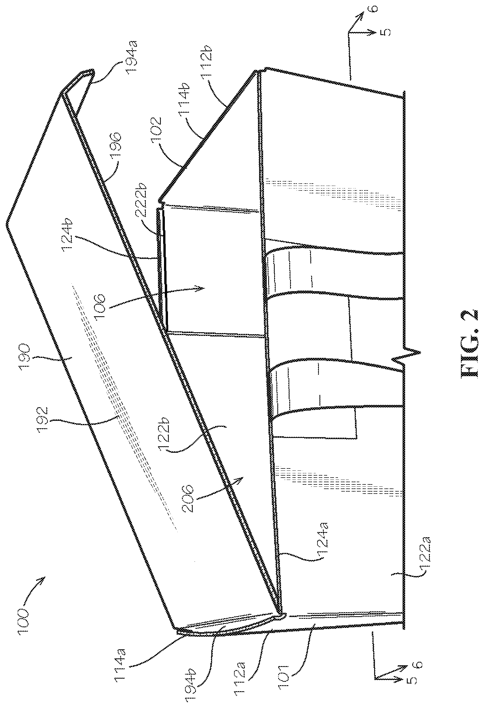
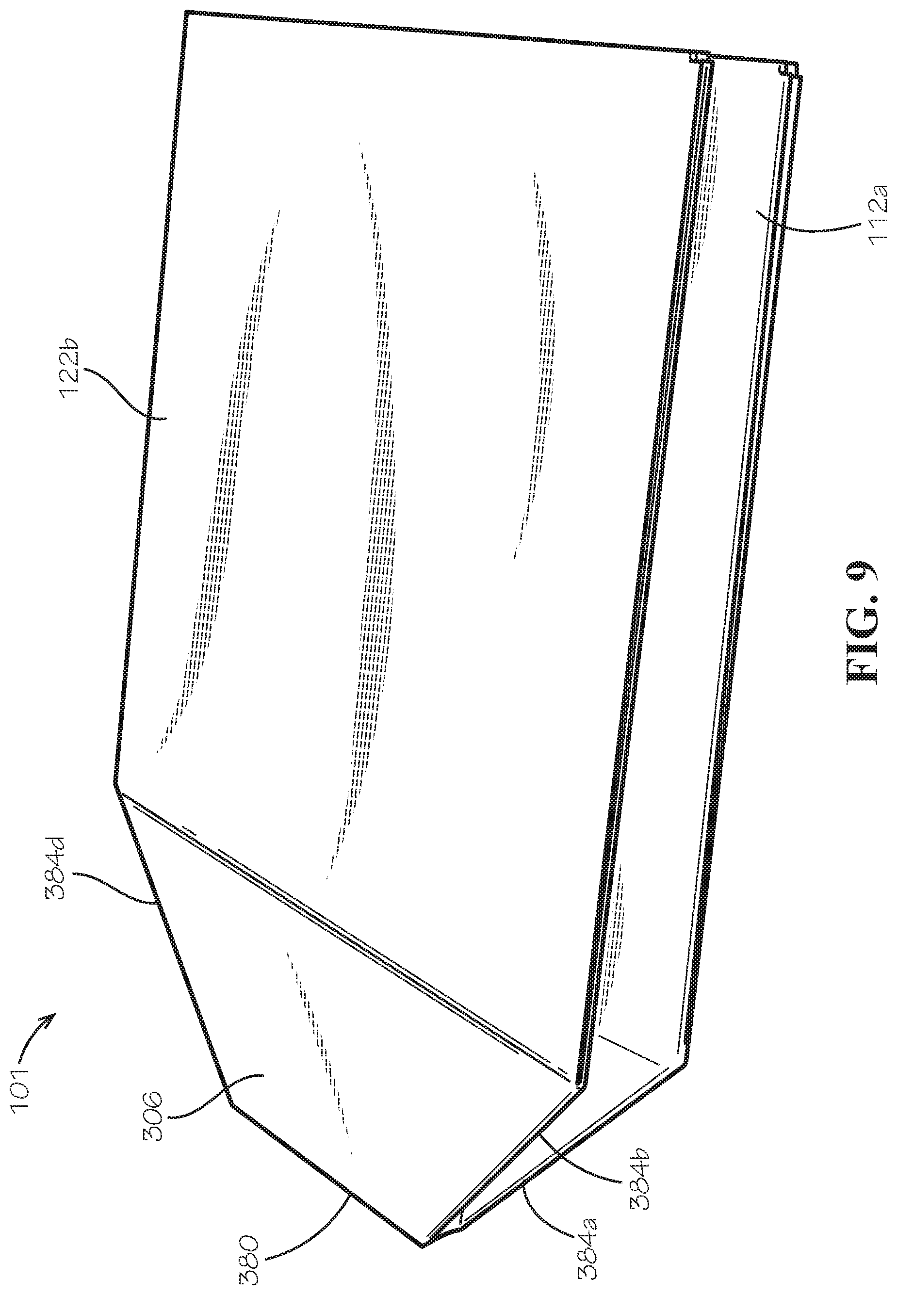
FIG. 1 is a perspective view of a modular box assembly 100 in a closed position in accordance with one aspect of the present disclosure. The modular box assembly 100 can comprise a box 101 and a variety of accessories configured to adapt the box for different applications, such as shipping hot goods, chilled goods, frozen goods, or goods at ambient temperature. FIGS. 1-18 depict these accessories as well as several different exemplary configurations for the box 101. In one aspect, the box can be adjustable about and between an expanded configuration (illustrated in FIG. 1) in which the box 101 has an expanded volume, and a collapsed configuration (illustrated in FIG. 9) in which the box has a collapsed volume that is less than the expanded volume. In the expanded configuration, the box 101 can be used to contain goods for shipment, and while in the collapsed configuration, the box takes up a minimal amount of space and thus the box 101 can be shipped and stored in the collapsed configuration for space-efficient packing. In use, a user can simply press a portion of the box against a surface, such as the ground, and the box 101 can reconfigure to the expanded configuration.
In the present aspect, the modular box assembly 100 can comprise the box 101, at least one handle 170, and a box top 190. The box can be configured as one aspect of an insulated box 110 comprising at least one insulating liner 2310. The box 101 can comprise a rigid board material such as corrugated cardboard; however in other aspects, the box can comprise other suitable rigid board materials, such as wood, plastic, metal, or any other material. The box 101 can be configured as an uninsulated box, useful when, for example, goods are transported at ambient temperature. In other aspects, however, the insulated box 110 can be configured to transport hot, chilled, or frozen goods, and the at least one liner 2310 can help maintain a desired temperature within the insulated box. The box 101 can also be conveyable, such as on a conveyor belt, and the box can be rigid and strong enough to resist collapse on the conveyor belt. The box 101 is but one example of a box, and the methods discussed below for insulating the box to form the insulated box 110 can be applied to a box of another shape, size, or form.
The box 101 can comprise a first pair of opposing side panels 112a,b and a second pair of opposing side panels 122a,b. That is, the box can comprise a first side panel 112a, a second side panel 112b opposed to the first side panel, a third side panel 122a positioned between the first side panel 112a and the second side panel 112b, and a fourth side panel 122b opposed to the third side panel 122a and positioned between the first and second side panels 112a,b. The side panels 112a,b,122a,b can each be a rigid panel. In one aspect, the side panel 112a can be substantially parallel to the side panel 112b, and the side panel 122a can be substantially parallel to the side panel 122b. Each of the first pair of side panels 112a,b can be substantially perpendicular to the second pair of side panels 122a,b. In one aspect, the box 101 can define a rectangular or square cross-sectional shape; however, in other aspects, the box can define a different cross-sectional shape such as a circular, triangular, pentagonal, or hexagonal, shape or any other desired shape.
The box 101 can have a top end 102 and a bottom end 104 disposed opposite from the top end. In one aspect, each side panel of the second pair of side panels 122a,b can define lips 124a,b, respectively, disposed proximate to the top end 102 of the box. In another aspect, each side panel of the first pair of side panels 112a,b can define lips 114a,b, respectively, disposed proximate to the top end 102 of the box. The box 101 can define a box opening 106 at the top end 102. The box top 190 can be sized and shaped to fit between at least a portion of the first pair of side panels 112a,b and the second pair of side panels 122a,b to cover the box opening when the box is in the closed position. In one aspect, the lips 114a,b,124a,b can be configured to be flush with a top panel 192 of the box top 190 when the box is in the closed position.
The handle 170 can facilitate hand carrying of the box 101. In one aspect, the handle 170 can be formed from a flat paper or tape such as a heavy kraft paper, plastic, posterboard, cardboard, or other suitable materials. In another aspect, the handle 170 can be formed from twisted paper rope. In still other aspects, the handle 170 can comprise a fiber such as cotton, hemp, jute, or bamboo fiber.
In one aspect, the handle 170 can be attached to the box 101 with an adhesive, such as a glue, cement, epoxy, mastic, double-sided tape, cohesive, a water activated tape or any other suitable material. In other aspects, the handle 170 can be mechanically attached, such as with a hook-and-loop fastener, stitching, or staples, and the mechanical attachment of the handle can be configured to be selectively attached and detached from the box 101 such as with hook-and-loop fasteners.
In another aspect, the handle 170 can be a U-shaped handle having a first end 172 and a second end 174 of the handle 170 adhered to the same side panel 122a, and a central portion 176 of the handle extending away from the side panel 122a. The first end 172 and the second end 174 of the handle 170 can be sized and configured such that a surface area of each end 172, 174 is large enough that an adhesive applied to each end 172, 174 and/or the side panel 122a can adhere the handle 170 to the box 101 with sufficient shear strength and with sufficient side-pull strength. For example, if the handle 170 is formed from flat paper, the first end 172 and the second end 174 of the handle 170 can be attached to the side panel 122a with water activated tape. The size of the first end 172 and the second end 174 can be selected so that the ends 172, 174 have sufficient surface area for the water activated tape to securedly adhere the ends 172, 174 to the box 101.
In one aspect, the at least one handle 170 can comprise a plurality of handles, such as two, three, four or more handles. In this aspect, each handle 170 can be coupled to the same or a different side panel than the other handles.
FIG. 2 is a perspective view of the modular box assembly 100 of FIG. 1 with the box top 190 in a partially open position. In an open position, the box top can be removed from the box opening 106, thereby exposing a box cavity 206 defined within the box 101. The first pair of opposing side panels 112a,b and the second pair of opposing side panels 122a,b of the box 101 can define the box cavity 206. A pair of shoulders 222a,b can extend inwards into the box cavity 206 from each of the side panels 122a,b, as represented by the shoulder 222b (shoulder 222a shown in FIG. 5). The shoulders 222a,b can be spaced from the top end 102 a predetermined distance and can be configured to support the box top 190 when the box top 190 is in the closed position. In the closed position, the box top 190 can cover the box opening 106 and enclose the box cavity 206.
FIG. 3 is a perspective view of the modular box assembly 100 of FIG. 1 in a collapsed and bundled configuration, according to one aspect. In this aspect, the box 101 can be in a collapsed configuration as further discussed below with respect to FIG. 9. If the box 101 is an insulated box 110, the insulating liner 2310 can be folded and positioned adjacent to the collapsed box 101, such as on top of the collapsed box 101. The box top 190 can be position on top of the liner 2310 or the collapsed box 101, with a pair of opposed side tabs 194a,b (illustrated in FIG. 4) of the box top 190 wrapping around at least a portion of the liner 2310 and/or the collapsed box 101. That is, in one aspect, the side tabs 194a,b of the box top 190 can be configured to wrap around and help contain the liner 2310 and/or the box 101 when the modular box assembly 100 is in the collapsed and bundled configuration. In another aspect, the modular box assembly 100 can further comprise at least one strap 12 configured to hold the box top 190, the box 101, and/or the liner 2310 in the collapsed and bundled configuration.
Referring now to FIG. 4, in the present aspect, the box top 190 can be formed separate from the box 101 and can comprise the top panel 192 and the pair of opposed side tabs 194a,b extending away from the top panel 192. In another aspect, each side tab 194a,b can have a width D1 that is less than a width D2 of the top panel 192. In use, described more fully below, the side tabs 194a,b can extend away from the top panel 192 so that the side tabs 194a,b can be positioned in the box cavity 206. The box top 190 can be configured to fit over the top end 102 of the box 101 so that a lower surface 196 of the top panel 192 rests on the shoulders 222a,b of the box 101. The narrower width of the side tabs 194a,b relative to the top panel 192 can allow the side panels 194a,b to fit between the shoulder 222a,b.
In one aspect, the top panel can be a rigid panel. Optionally, in other aspects, the box top can further comprise an insulated panel coupled to the top panel 192. For example, the insulated panel can be positioned beneath the top panel. In other aspects, the box top 190 need not comprise the insulated panel, and the top panel 192 can be uninsulated. The box top can comprise corrugated cardboard in the present aspect; however, in other aspects the box top can be comprise a suitable rigid board material such as wood, plastic, metal, or any other material.
FIG. 5 is a cross-section of the box 101 of FIG. 1 taken along line 5-5 shown in FIG. 2, with the handle 170 and the box top 190 removed. In one aspect, each shoulder 222a,b can comprise two sub-shoulders 322. The shoulder 222a can comprise sub-shoulders 322a,b, and the shoulder 222b can comprise sub-shoulders 322c,d. The sub-shoulders 322a-d can be defined by a plurality of first wings 312a-d and a plurality of second wings 324a-d. The first wings 312a,b can be attached at opposite sides of the side panel 112a, and the first wings 312c,d can be attached at opposite sides of the side panel 112b. The second wings 324a,b can be attached at opposite sides of the side panel 122a, and the second wings 324c,d can be attached at opposite sides of the side panel 122b.
The second wing 324a can be folded inwards at a hinge 365a and positioned adjacent to an inner side surface 326a of by the side panel 122a, and the first wing 312c can be folded at a hinge 370c and positioned adjacent to the second wing 324a. The second wing 324a and the first wing 312c can be secured in position, such as with an adhesive, to form the sub-shoulder 322a. The second wing 324b can be folded inwards at a hinge 365b and positioned adjacent to the inner side surface 326a, and the first wing 312a can be folded at a hinge 370a and positioned adjacent to the second wing 324b. The second wing 324b and the first wing 312a can be secured in position, such as with an adhesive, to form the sub-shoulder 322b.
To form the sub-shoulder 322c of shoulder 222b, the second wing 324c can be folded inward at a hinge 365c and positioned adjacent to an inner side surface 326b of by the side panel 122b. The first wing 312d can be folded at a hinge 370d and positioned adjacent to the second wing 324c. The first wing 312d and the second wing 324c can be secured in position, such as with an adhesive, to form the sub-shoulder 322c. To form the sub-shoulder 322d of shoulder 222b, the second wing 324d can be folded inward at a hinge 365d and positioned adjacent to the inner side surface 326b. The first wing 312b can be folded at a hinge 370b and positioned adjacent to the second wing 324d. The first wing 312b and the second wing 324d can be secured in position, such as with an adhesive, to form the sub-shoulder 322d.
The formation of the sub-shoulders 322a-d can also secure each of the first pair of side panels 112a,b to each of the second pair of side panels 122a,b, thereby defining the square or rectangular horizontal cross-section of the box 101. In one aspect, the box can further comprise a bottom panel 306. The bottom panel can be a rigid panel. The bottom panel 306 can be disposed at the bottom end 104 of the box 101, and the bottom panel 306 can be attached to each of the side panels 112a,b,122a,b. The bottom panel can further define the box cavity 206. According to example aspects, the bottom panel 306 can define a square or rectangular shape defined by four bottom panel edges 310a-d. The bottom panel 306 can further define four bottom panel corners 308a-d, as shown.
In the present aspect, the bottom panel 306 can define a center subpanel 380 disposed substantially at a center of the bottom panel 306. The center subpanel 380 can be substantially rectangular in shape. A center fold line 382 such as, for example, a scored crease, can extend between the center subpanel 380 and each side panel 112a,b, and the center fold line can substantially bisect the bottom panel 306, with the exception of within the center subpanel 380. The center fold line 382 can also bisect each side panel 112a,b, as shown and further described with respect to FIG. 7. Example aspects of the center fold line 382 can be substantially aligned with a longitudinal center line 387 of the box 101, as shown. A transverse center line 389 of the box 101 can be oriented about perpendicular to the longitudinal center line 387 and the center fold line 382. In one aspect, and with respect to FIG. 8, the center fold line 382 can comprise a double center fold line. That is, the center fold line can comprise at least a first center fold line 382a and a second center fold line 382b positioned adjacent to each other. In this aspect, the center fold line can comprise two substantially parallel fold lines spaced a predetermined distance apart. In another aspect, the distance between the center fold lines 382a,b can be less than a width of the center subpanel 380. According to example aspects, the rectangular center subpanel 380 can be defined by a first pair of edge fold lines 381a,b extending in a longitudinal direction and a second pair of edge fold lines 383a,b extending transverse to the first pair of edge fold lines 381a,b. The center subpanel 380 can define four subpanel corners 385a-d, wherein each subpanel corner 385a-d can join a corresponding one of the first pair of edge fold lines 381a,b with a corresponding one of the second pair of edge fold lines 383a,b.
In one aspect, four corner fold lines 384a-d can extend between the corners of the center subpanel 380 and the hinges 370a-d. For example, a first corner fold line 384a can extend from a first hinge 370a to the center subpanel 380, a second corner fold line 384b can extend from a second hinge 370b to the center subpanel 380, a third corner fold line 384c can extend from a third hinge 370c to the center subpanel 380 and a fourth corner fold line 384d can extend from a fourth hinge 370d to the center subpanel 380.
A plurality of V-shaped fold lines 386a-f can extend between the hinges 370a-d and the center fold line 382. In one aspect, the V-shaped fold lines 386a-c can each extend from the first hinge 370a to the center fold line 382 and then to the second hinge 370b. The V-shaped fold lines 386a-c can be defined between the corner fold lines 384a and 384b. The V-shaped fold lines 386d-f can each extend from the third hinge 370c to the center fold line 382 and then to the fourth hinge 370d. The V-shaped fold lines 386d-f can be defined between the corner fold lines 384c and 384d. In use, the center subpanel 380, the center fold line 382, the corner fold lines 384a-d, and the V-shaped fold lines 386a-f can cooperate to collapse the box 101. Optionally, the center subpanel 380, the center fold line 382, the corner fold lines 384a-d, and the V-shaped fold lines 386a-f can provide the bottom panel with a truncated pyramidal shape when collapsed, as further discussed below with respect to FIG. 9. As shown, each of the V-shaped fold lines 386a-f can comprise a first fold line 388a and a second fold line 388b. For example, each of the V-shaped fold lines 386a-c can define the first fold line 388a extending from the first corner to the center fold line 382 (i.e., the longitudinal center line 387) and the corresponding second fold line 388b extending from the second corner to the center fold line 382, such the each pair of corresponding first and second fold lines 388a,b meet at an apex 190 along the center fold line.
FIG. 6 is a cross-section of the modular box assembly 100 of FIG. 1 taken along line 6-6 shown in FIG. 2. In the present view, the handle 170 has been removed for clarity. In one aspect, the box top 190 can be positioned on the two sub-shoulders 322a,b of the box 101 such that an upper surface 199 of the top panel 192 of the box top 190 is substantially flush with the top end 102 of the box 101. In one aspect, at least one of the bottom panel 306 and the side panels 112a,b can have a single wall material thickness. In another aspect, at least one of the bottom panel and the side panels 112a,b can be uninsulated.
FIGS. 7 and 8 are top views of box blanks 710 which can be assembled to form the box 101. In one aspect, the box blank 710 can define four corner fold lines 750a-d, such as a scored crease. In other aspects, the box blank 710 can define cuts in place of the corner fold lines 750a-d. A first corner fold line 750a can extend outwards from the bottom panel 306 to separate the first wing 312a from the second wing 324b. A second corner fold line 750b can extend outwards from the bottom panel 306 to separate the first wing 312b from the second wing 324d. A third corner fold line 750c can extend outwards from the bottom panel 306 to separate the first wing 312c from the second wing 324a. A fourth corner fold line 750d can extend outwards from the bottom panel 306 to separate the first wing 312d from the second wing 324c. In the present aspect, the adjacent first wings 312a-d and first wings 324a-d can be hingedly connected by the corner fold lines 750a-d. In other aspects, the corner fold lines 750a-d can be cuts which separate the adjacent first wings 312a-d and second wings 324a-d.
In one aspect, the box blank 710 can further define a first length fold line 712a and a second length fold line 712b extending from the side panel 112a to the side panel 112b. The first length fold line 712a can facilitate folding of the first wing 312a relative to the side panel 112a, the side panel 122a relative to the bottom panel 306, and the first wing 312c relative to the second side panel 112b. The second length fold line 712b can facilitate folding of the first wing 312b relative to the side panel 112a, the side panel 122b relative to the bottom panel 306, and the first wing 312d relative to the side panel 112b.
The box blank 710 can further define a first width fold line 722a and a second width fold line 722b. In one aspect, the width fold lines 722a,b can be substantially perpendicular to the length fold lines 712a,b. The first width fold line 722a can facilitate folding of the second wing 324a relative to the side panel 122a, the side panel 112b relative to the bottom panel 306, and the second wing 324c relative to the side panel 122b. The second width fold line 722b can facilitate folding of the second wing 324b relative to the side panel 122a, the side panel 112a relative to the bottom panel 306, and the second wing 324d relative to the side panel 122b.
The center fold line 382 can extend across and substantially bisect each side panel 112a,b. In one aspect, the center fold line can facilitate each of the side panels 112a,b folding inwards about the center fold line 382 and towards the bottom panel 306 to facilitate collapsing the box 101 as shown in FIG. 9. If the center fold line comprise a double center fold line 382a,b, as illustrated in FIG. 8, the center fold lines can facilitate each of the side panels 112a,b more easily folding inwards about the first center fold line 382a and the second center fold line 382b and towards the bottom panel 306 to facilitate collapsing the box 101.
FIG. 9 is a perspective view of the box 101 of FIG. 1 in a collapsed configuration. In the present view, the handle 170 and the box top 190 are removed for clarity. As the box 101 collapses, the side panels 122a,b move inwards and towards one another, and the side panels 112a,b fold inwards towards one another. The V-shaped fold lines 386a-f (shown in FIG. 5) cooperate to transition the bottom panel 306 from a substantially planar shape to the truncated pyramidal shape. In the truncated pyramidal shape, the center subpanel 380 extends outwards and away from the side panels 112a,b and the side panels 122a,b. Exerting a force upon the center subpanel 380, such as by positioning the center subpanel on a surface and urging the side panels 112a,b, 122a,b towards the center subpanel 380 can cause the box to self-expand into an expanded configuration (shown in FIG. 1) with a substantially rectangular prism shape. The self-expanding action can be desirable to allow for quick and easy reconfiguration of the box 101, unlike many boxes which must be folded and taped together. The box can be shipped and stored in the collapsed configuration for space-efficient packing, and a user can simply press upon the center subpanel 380, such as by pressing the center subpanel against the ground, and the box 101 can reconfigure to the expanded configuration.
With reference again to FIGS. 1 and 2, the box top 190 can be positioned on the box 101 to cover the box opening 106 and enclose the box cavity 206. In one aspect, the box top 190 can comprise the top panel 192 and a pair of side tabs, as represented by side tabs 194a,b extending down from the top panel 192. The box top 190 can be configured to fit over the top end 102 of the box 101 so that the lower surface 196 of the top panel rests on the shoulders 222a,b of the box. The side tabs can extend away from the top panel 192 so that the side tabs 194a,b can be positioned in the box cavity 206. In one aspect, the lips 114a,b,124a,b can extend upwards from the shoulders 222a,b by a height substantially equal to a thickness of the top panel 192 such that the top panel rests substantially flush with the lips 114a,b,124a,b (as illustrated in FIG. 1). That is, with the box top 190 in the closed position, the top panel 192 can be substantially flush with the top end 102 of the box 101. In other aspects, the lips 114a,b,124a,b can extend upwards beyond the top panel 190.
The box top 190 can be secured to the box 101 by tape, banding, a strap, adhesive, or other restraint mechanism. For example, at least one tape strip 198 can extend from the side panel 112a, over the top panel 192, and down the side panel 112b to secure the top panel to the box 101. In some aspects, the tape can be a water activated tape or any other suitable material.
In one aspect, the rigidity of the box top 190 can be desirable to prevent inadvertent collapse of the box 101. Collapse of one aspect of the box is demonstrated in FIG. 9. Inadvertent or accidental collapse of the box 101 during shipping or handling can crush or damage the contents of the box. By placing the box top in the box cavity 206 such that the side tabs 194a,b of the box top 190 can engage or contact the side panels 112a,b of the box, the rigidity of the box top can prevent or restrict folding of the bottom panel 306 along the center fold line 382, the corner fold lines 384a-d, and/or the V-shaped fold lines 386a-f, thereby preventing collapse of the box 101.
FIGS. 10 and 11 are perspective views of the interior of the box 101 in the expanded configuration, according to various aspects. As demonstrated by the shoulder 222a, each shoulder 222a,b can define a shoulder channel 1922a,b. In one aspect, a first shoulder channel 1922a can be defined by the side panel 122a and the two sub-shoulders 322a,b of the shoulder 222a, and a second shoulder channel 1922b can be defined by the side panel 122b and the two sub-shoulders 322c,d of the shoulder 222b. The shoulder channel 1922a can be representative of both shoulder channels 1922a,b, though shoulder channel 1922a is not necessarily representative of both shoulder channels 1922a,b.
In one aspect, each shoulder channel 1922a,b can have a channel width having a predetermined distance. For example and as illustrated in FIG. 10, the channel width can be greater than zero such that a distal edge 1924a of the first wing 312a is spaced from a distal edge 1924c of the first wing 312c, and a distal edge 1926a of the second wing 324a is spaced from a distal edge 1926b of the second wing 324b. In another example and as illustrated in FIG. 11, the channel width can be substantially zero such that the distal edge 1924a of the first wing 312a is adjacent to and/or in contact with the distal edge 1924c of the first wing 312c and the distal edge 1926a of the second wing 324a is adjacent to and/or in contact with the distal edge 1926b of the second wing 324b. In another aspect, the predetermined distance of the channel width of each shoulder channel 1922a,b can be any distance between zero and the width of the side panel 122a,b.
In the present aspect, the first wings 312a,c can be substantially flush with the second wings 324a,b of the sub-shoulders 322a,b. In other aspects, the first wings 312a,c can extend further into the support channel 1922a than the second wings 324a,b to provide a groove (not shown) between the first wing 312a, the second wing 324b, and the side panel 122a and another groove between the first wing 312c, the second wing 324b, and the side panel 122a.
In one aspect, the box 101 can be the insulated box 110 comprising at least one liner 2310, such as an A-B liner and the like configured to be positioned in the box cavity 206 of the box. FIG. 12 is an exploded perspective view of an insulated box in accordance with another aspect of the present disclosure. The insulated box 110 of the present aspect can be an internally insulated box. In another aspect, the liner can be easily insertable and/or removable from the box cavity 206 of the insulated box 110.
In one aspect, the liner 2310 can comprise a first liner 2312a and a second liner 2312b. In this aspect, each of the first liner and the second liner can be formed by insulated panels 510 which can each be folded into a desired shape, such as, for example and without limitation, C-shaped, U-shaped and L-shaped.
The first liner 2312a can comprise a center panel 2314a disposed between at least one of a first liner side panel 2316a and a second liner side panel 2316b. A border 158 of the first liner 2312a can comprise a first end border portion 2320a defined by the first liner side panel 2316a and a second end border portion 2320b defined by the second liner side panel 2316b and disposed opposite from the first end portion 2320a. A fold 2318a can be defined between the first liner side panel 2316a and the center panel 2314a, and a fold 2318b can be defined between the second liner side panel 2316b and the center panel 2314a. A pair of side border portions 2322a,b of the border 158 can be defined by the liner side panels 2316a,b and the center panel 2314a, and the side border portions 2322a,b can extend between the respective end border portions 2320a,b.
The second liner 2312b can comprise a center panel 2314b disposed between at least one of a first liner side panel 2316c and a second liner side panel 2316d. The border 158 of the second liner 2312b can comprise a first end border portion 2320c defined by the first liner side panel 2316c and a second end border portion 2320d defined by the second liner side panel 2316d and disposed opposite from the first end border portion 2320c. A fold 2318c can be defined between the first liner side panel 2316c and the center panel 2314b, and a fold 2318d can be defined between the second liner side panel 2316d and the center panel 2314b. A pair of side border portions 2322c,d of the border 158 can be defined by the liner side panels 2316c,d and the center panel 2314b, and the side border portions 2322c,d can extend between the respective end border portions 2320c,d.
The first liner 2312a and the second liner 2312b can fit together to define a substantially cubic or rectangular prism shape with an inner insulated cavity (not shown) defined by the A-B liner 2310. The end border portions 2320a,b of the border 158 of the first liner 2312a can contact the center panel 2314b of the second liner 2312b, and the end border portions 2320c,d of the border 158 of the second liner 2312b can contact the center panel 2314a of the first liner 2312a. The side border portions 2322c,d of the border 158 of the second liner 2312b can each extend around the sides of a different one of the liner side panels 2316a,b. The side border portions 2322a,b of the border 158 of the first liner 2312a can each extend around the sides of a different one of the liner side panels 2316c,d.
In the present aspect, the liner 2310 can be oriented so that the center panel 2314a of the first liner 2312a substantially covers the box opening 106 of the box 101, the center panel 2314b of the second liner 2312b substantially covers the bottom panel 306, and the liner side panels 2316a,b,c,d substantially cover the side panels 112a,b,122a,b of the box 101. In the present aspect, the side panels liner 2316a,b can substantially cover the side panels 122a,b, and the side panels liner 2316c,d can substantially cover the side panels 112a,b. In other aspects, the side panels liner 2316a,b can substantially cover the side panels 112a,b, and the liner side panels 2316c,d can substantially cover the side panels 122a,b.
In still other aspects and as illustrated in FIG. 13, the liner 2310 can be orientated such that the first liner side panel 2316a of the first liner 2312a substantially covers the box opening 106, and the second liner side panel 2316b of the first liner 2312a substantially covers the bottom panel 306 of the box 101. The side panels 112a,b,122a,b of the box 101 can be substantially covered by the second liner 2312b and the center panel 2314a of the first liner 2312a. Such a configuration can be desirable because the first liner side panel 2316a can act as a lid which can be folded about the fold 2318a to open and close the inner insulated cavity of the liner 2310 without requiring removal of either of the first and second liners 2312a,b from the insulated box 110. As can be appreciated, other arrangements of the first liner 2312a relative to the second liner 2312b are contemplated.
In one aspect, the liner 2310 can be the A-B liner configured such that the first liner 2312a engages portions of the second liner 2312b to form the inner insulated cavity of the liner 2310, as shown in FIGS. 12 and 13. That is, the first liner and the second liner can be arranged in a "trunk-lid" configuration. Optionally, in other aspects, in applications in which less insulation is needed or desired, only one of the first liner 2312a or the second liner 2312b can be positioned in the box cavity 206. In this aspect, for example, the second liner 2312b can be oriented so that the center panel 2314b of the second liner 2312b substantially covers the bottom panel 306, and the liner side panels 2316c,d of the second liner substantially cover the side panels 112a,b of the box 101. Note that less insulation can be needed along side panels 122a and 122 because of the triple-wall material thickness on these panels, as can be seen in FIG. 5.
Referring now to FIG. 14, in one aspect, the liner 2310 can comprise an insulation batt 350, a first sheet 352, and a second sheet 354. In another aspect, the first sheet 352 and the second sheet 354 can be sized and shaped complimentary to each other; however in some aspects, the sheets 352,354 can differ in size and shape. The insulation batt 350 and the sheets 352,354 can each be flat and substantially planar before assembly. In the present aspect, the insulation batt 350 can be approximately 3/8 inches thick; however this thickness is not limiting. The thickness can range from 1/16 inches to over 2 inches, such as a range of 1/4 inches to 1/2 inches.
The insulation batt 350 can be positioned between the first sheet 352 and the second sheet 354 in a panel cavity 351 defined between the first sheet and the second sheet. The sheets 352,354 can be sized to overhang the insulation batt 350 on all sides with perimeter portions of the first sheet and second sheet extending beyond a perimeter 359 of the insulation batt 350. In one aspect, the insulation batt can be encapsulated by the border 158 which can extend around the perimeter of the insulation batt 350, thereby sealing the panel cavity 351. The panel cavity containing the insulation batt can define an insulated portion 161 of the liner 2310. In another aspect, the border 158 can be a seam formed by attaching a perimeter portion of the first sheet 352 which overhangs the perimeter 359 of the insulation batt 350 with a perimeter portion of the second sheet 354 which also overhangs the perimeter 359 of the insulation batt 350. The first sheet 352 can be attached to the second sheet 354 with an adhesive such as a glue, cement, epoxy, mastic, cohesive, double-side tape or other suitable adhesive to form the border 158. In some aspects, the border 158 can be formed by mechanically fastening the first sheet 352 to the second sheet 354, such as by stapling, stitching, or any other suitable method of fastening.
The fold 2318 can be defined in the liner 2310 a predetermined distance from the border 158. For example, the fold 2318a and the fold 2318b can be substantially equally spaced relative to the border of the first liner 2312a so that the first liner side panel 2316a and the second liner side panel 2316b have substantially the same area. In one aspect, the insulation batt 350 can extend through each fold 2318. In other aspects, however, the insulation batt can be disjoint so that the insulation batt 350 does not extend through the fold such that the side panels and the center panels 2314 are easily folded relative to each other.
FIG. 15 is a perspective view of an inner box 1500, according to one aspect, and FIG. 16 is a top view of an inner box blank 1600 of the inner box 1500. The inner box blank 1600 can comprise a center panel 1610, a pair of side flap panels 1618a,b attached at opposite ends of the center panel 1610, and a first locking panel 1614 and a second locking panel 1616 disposed at opposite ends of the center panel 1610. Each side flap panel 1618a,b can comprise a side subpanel 1540a,b respectively attached to the center panel 1610 and a flap subpanel 1640a,b disposed opposite from the center panel 1610. Each side subpanel 1540a,b can comprise a side tab 1642a,b, respectively. Each side tab 1642a,b can be cut out from the respective flap subpanel 1640a,b by a side tab cutout 1643a,b, respectively. Each side tab 1642a,b can be configured to extend outwards from the flap subpanel 1640a,b when the side tabs 1642a,b are folded relative to the flap subpanels 1640a,b.
The first locking panel 1614 can comprise a side subpanel 1532a attached to the center panel 1610 and a first locking subpanel 1510 disposed opposite from the center panel 1610. The first locking subpanel 1510 can comprise a pair of wings 1512a,b, and each wing 1512a,b can define a locking slot 1514a,b. The first locking subpanel 1510 can also comprise a channel tab 1530a which can be cut out from the side subpanel 1532a. The channel tab 1530a can be configured to extend outwards from the side subpanel 1532a when the first locking subpanel 1510 is folded relative to the side subpanel 1532a.
The second locking panel 1616 can comprise a side subpanel 1532b attached to the center panel 1610 and a second locking subpanel 1520 disposed opposite from the center panel 1610. The second locking subpanel 1520 can comprise a pair of locking tabs 1522a,b which can be hingedly attached to the second locking subpanel 1520. A pair of locking notches 1624a,b can be defined between the second locking subpanel 1520 and the locking tabs 1522a,b. The second locking subpanel 1520 can also comprise a channel tab 1530b which can be cut out from the side subpanel 1532b. The channel tab 1530b can be configured to extend outwards from the side subpanel 1532b when the second locking subpanel 1520 is folded relative to the side subpanel 1532b.
In an assembled configuration shown in FIG. 15, the side subpanels 1532a,b, 1540a,b can define four sides of the inner box 1500. The center panel 1610 can define a bottom panel of the inner box 1500. The first locking subpanel 1510 and the second locking subpanel 1520 can overlap to define a top panel of the inner box 1500. The side flap panels 1618a,b can be folded inwards so that the flap subpanels 1640a,b lie flat against the first locking subpanel 1510 and the second locking subpanel 1520. The side tabs 1642a,b can engage the locking slots 1514a,b of the first locking subpanel 1510 to prevent the side flap panels 1618a,b from unfolding. Additionally, locking tabs 1522a,b can extend through the locking slots 1514a,b and through openings defined by the side tap cutouts 1643a,b to prevent the side flap panels 1618a,b from unfolding.
With the locking tabs 1522a,b extending through the locking slots 1514a,b, the first locking subpanel 1510 can be secured to the second locking subpanel 1520. The locking notches 1624a,b can engage the locking slots 1514a,b to prevent withdrawal of the locking tabs 1522a,b from the locking slots 1514a,b. The second locking subpanel 1520 can be positioned overlapping the first locking subpanel 1510, and the locking tabs 1522a,b can be inserted through the locking slots 1514a,b to secure the first locking subpanel 1510 to the second locking subpanel 1520. In one aspect, the inner box 1500 can be sized to fit closely within the box cavity 206. Optionally, the wings 1512a,b of the inner box can contact the side panels 112a,b. In some aspects, the channel tabs 1530a,b of the inner box 1500 can extend outwards from the inner box and engage a portion of the liner 2310, such as the border 158 of the liner, to secure and suspend the inner box 1500 within the box cavity 206, as shown in FIG. 17. In other aspects, however, the inner box 1500 can be sized to fit closely within the box cavity can be positioned on contents 10 of the box, as shown in FIG. 18. That is, in some aspects, the inner box 1500 can be positioned directly on the contents 10 of the box 101 in the box cavity 206 regardless of the presence or absence of the liner 2310.
For example, if the liner 2310 is orientated as in FIG. 13 with the first liner side panel 2316a of the first liner 2312a covering the box opening 106, the inner box 1500 can be placed in the box cavity 206 by lifting the first liner side panel 2316a of the first liner 2312a like a lid which can be opened and closed. The inner box 1500 can engage a portion of the second liner 2312b to secure and suspend the inner box 1500 within the box cavity 206, and the first liner side panel 2316a can be lower into the box cavity 206 over the inner box 1500. Alternatively, in another example, if the liner 2310 is orientated as in FIG. 13 with the first liner side panel 2316a of the first liner 2312a covering the box opening 106, the inner box 1500 can be placed in the box cavity 206 by lifting the first liner side panel 2316a of the first liner 2312a. The inner box 1500 can be positioned directly on the contents 10 of the box 101 in the box cavity 206 and the first liner side panel 2316a can be lower into the box cavity 206.
In one aspect, the inner box 1500 can contain a temperature maintaining material 2110 positioned within a cavity 2108 of the inner box. In some aspects, the inner box 1500 can contain a cooling material, such as, for example and without limitation, carbon dioxide dry ice, configured to keep contents of the insulated box 110 cold or frozen. In such aspects, as the dry ice sublimes into carbon dioxide gas, the cold carbon dioxide gas can pass downwards from the inner box 1500 through a plurality of vents 1612 defined by the center panel 1610, which can be oriented as the bottom panel. The inner box can prevent a user from making direct contact with the dry ice by which can cause burns to bare skin. In other aspects, the inner box 1500 can contain a different temperature maintaining material configured to cool the insulated box 110. For example, in some aspects, the temperature maintaining material 2110 can be a mixture of materials configured to undergo a controlled endothermic reaction. For example and without limitation, the temperature maintaining material can comprise water, ammonium nitrate, calcium ammonium nitrate, and/or urea in a container which can undergo an endothermic reaction as the water dissolves solid material in the container, as commonly used in so-called "instant ice packs". In such aspects, the temperature maintaining material 2110 can absorb heat through the endothermic reaction.
In other aspects, the temperature maintaining material 2110 can be a heat emitting material configured to keep contents of the insulated box 110 warm or hot. For example and without limitation, the inner box 1500 can contain heat packs which emit residual heat from a heated material defining a high specific heat capacity. For example, a heated water bottle or bag can emit residual heat over time. In other aspects, the inner box can contain a heat emitting material which can undergo a controlled exothermic reaction to produce heat within the insulated box 110. One example can include a pouch of supersaturated crystallizing solution, such as, for example and without limitation, sodium acetate, which release heat as crystallization occurs. Another example can be a mixture which can comprise cellulose, iron, activated carbon, vermiculite, and/or salt which can release heat as oxygen oxidizes the iron. In such aspects, the temperature maintaining material 2110 can produce heat through the exothermic reaction.
In the present aspect, the first sheet 352 and the second sheet 354 of the liner 2310 can comprise paper, such as kraft paper; however, in other embodiments, the sheets can comprise posterboard, cardboard, plastic sheeting, cellulose film, cloth, or any other suitable material. In some aspects, the sheets can comprise a water-proof or water-resistant material, such as water-proof paper. In some aspects, at least one of the first sheet 352 and the second sheet 354 of the liner can comprised a material different from another of the sheets. In the present aspect, the box 101 can comprise a paper fiber-based material such as corrugated cardboard or poster board; however, the box can be comprised of any suitable rigid board material such as wood, plastic, metal, or any other material.
The insulation batt 350 of the liner 2310 can comprise paper or other paper fiber materials; however, in other aspects, the insulation batts can comprise cotton, foam, rubber, plastics, fiberglass, mineral wool, or any other flexible insulation material. In the present application, the insulation batt can be repulpable. In the present aspect, the modular box assembly 100 can be 100% recyclable. In the present aspect, the modular box assembly can be single-stream recyclable wherein all materials comprised by the modular box assembly 100 can be recycled by a single processing train without requiring separation of any materials or components of the modular box assembly. In the present aspect, the modular box assembly 100 can be compostable. In the present aspect, the modular box assembly can be repulpable. In the present aspect, the modular box assembly 100 and at least each of the box 101, the box top 190 and the liner 2310 can be repulpable in accordance with the requirements of the Aug. 16, 2013, revision of the "Voluntary Standard For Repulping and Recycling Corrugated Fiberboard Treated to Improve Its Performance in the Presence of Water and Water Vapor" provided by the Fibre Box Association of Elk Grove Village, Ill. which is hereby incorporated in its entirety. In the present aspect, the modular box assembly 100 and at least each of the box 101, the box top 190 and the liner 2310 can be recyclable in accordance with the requirements of the Aug. 16, 2013, revision of the "Voluntary Standard For Repulping and Recycling Corrugated Fiberboard Treated to Improve Its Performance in the Presence of Water and Water Vapor" provided by the Fibre Box Association of Elk Grove Village, Ill.
Recyclable and repulpable insulation materials are further described in U.S. Patent Application No. 62/375,555, filed Aug. 16, 2016, U.S. Patent Application No. 62/419,894, filed Nov. 9, 2016, and U.S. Patent Application No. 62/437,365, filed Dec. 21, 2016, which are each incorporated by reference in their entirety herein.
The modular box assembly 100 can be used in applications in which a user wants to quickly open a box from the collapsed configuration of FIG. 9 to the expanded configuration of FIG. 1. In one aspect, by exerting a force upon at least one of the side panels 112a,b 122a,b in a direction towards the bottom end 104, with the center subpanel 380 held in place can cause the box to self-expand into an expanded configuration with a substantially rectangular prism shape. That is, by placing the center subpanel on a surface, such as the ground and pushing the box 101 against the ground can cause the box to self-expand into an expanded. The self-expanding action can be desirable to allow for quick and easy reconfiguration of the box 101, unlike many boxes which must be folded and taped together. The box can be shipped and stored in the collapsed configuration for space-efficient packing, and a user can simply press upon the center subpanel 380, such as by pressing the center subpanel against the ground, and the box 101 can reconfigure to the expanded configuration.
If an insulated box 110 is desired, with the box in the expanded configuration, the user can insert the liner 2310 into the box cavity 206. If further temperature control is desired, the inner box 1500 containing the temperature maintaining material 2110 can also be positioned within the box cavity.
The modular box assembly 100 can be used in applications in which a user or mail carrier transports perishable or temperature-sensitive goods, such as frozen, chilled, or hot goods. For example and without limitation, the modular box assembly 100 can be used to transport groceries, medications, electronics, or any other goods. The modular box assembly 100 can improve upon a common cardboard box by providing recyclable insulation to prevent spoilage of the contents. The modular box assembly 100 can also be used to deliver hot goods, such as warm foods.
In order to ship temperature-sensitive goods, common cardboard boxes are often packed with insulating materials made of plastics or foams which are not accepted by many recycling facilities or curb-side recycling programs in which a waste management service collects recyclables at a user's home. Consequently, shipping temperature-sensitive goods often produces non-recyclable waste which is deposited in landfills. The insulation materials often decompose very slowly, sometimes over the course of several centuries. In some instances, non-recyclable and non-biodegradable insulating materials can enter the oceans where the insulation materials can remain for years and harm marine life. In some aspects, the modular box assembly 100 can reduce waste and pollution by comprising materials which are recyclable or biodegradable. In aspects in which the modular box assembly 100 is curb-side or single-stream recyclable, the user may be more likely to recycle the modular box assembly 100 due to the ease of curb-side collection.
One should note that conditional language, such as, among others, "can," "could," "might," or "may," unless specifically stated otherwise, or otherwise understood within the context as used, is generally intended to convey that certain embodiments include, while other embodiments do not include, certain features, elements and/or steps. Thus, such conditional language is not generally intended to imply that features, elements and/or steps are in any way required for one or more particular embodiments or that one or more particular embodiments necessarily include logic for deciding, with or without user input or prompting, whether these features, elements and/or steps are included or are to be performed in any particular embodiment.
It should be emphasized that the above-described embodiments are merely possible examples of implementations, merely set forth for a clear understanding of the principles of the present disclosure. Any process descriptions or blocks in flow diagrams should be understood as representing modules, segments, or portions of code which include one or more executable instructions for implementing specific logical functions or steps in the process, and alternate implementations are included in which functions may not be included or executed at all, may be executed out of order from that shown or discussed, including substantially concurrently or in reverse order, depending on the functionality involved, as would be understood by those reasonably skilled in the art of the present disclosure. Many variations and modifications may be made to the above-described embodiment(s) without departing substantially from the spirit and principles of the present disclosure. Further, the scope of the present disclosure is intended to cover any and all combinations and sub-combinations of all elements, features, and aspects discussed above. All such modifications and variations are intended to be included herein within the scope of the present disclosure, and all possible claims to individual aspects or combinations
* * * * *
References
-
greencellfoam.com/shipping-coolers
-
www/chem-tran.com/packaging/supplies/cooliner-insulated-shipping-bags.php
-
peri-wrap.com/insulation
-
-
mhpn.com/product/thermopod_mailer_envelopes_and_thermokeeper_insulated_box_liners/packaging
-
tera-pak.com
-
hotcoldbags.com/items/Cool%20Green%20Bag
-
weiku.com/products/18248504/100_Biodegradable_Packing_materials_Green_Cell_Foam_Stock_Coolers.html
-
salazarpackaging.com/custom-packaging-and-design
-
corrugated.org/wp-content/uploads/PDFs/Recycling/Vol_Std_Protocol_2013
-
coldkeepers.com/product-category/shipping
-
needlesnknowledge.blogspot.com/2017/10/tall-box-with-lid.html
D00000
D00001
D00002
D00003
D00004
D00005
D00006
D00007
D00008
D00009
D00010
D00011
D00012
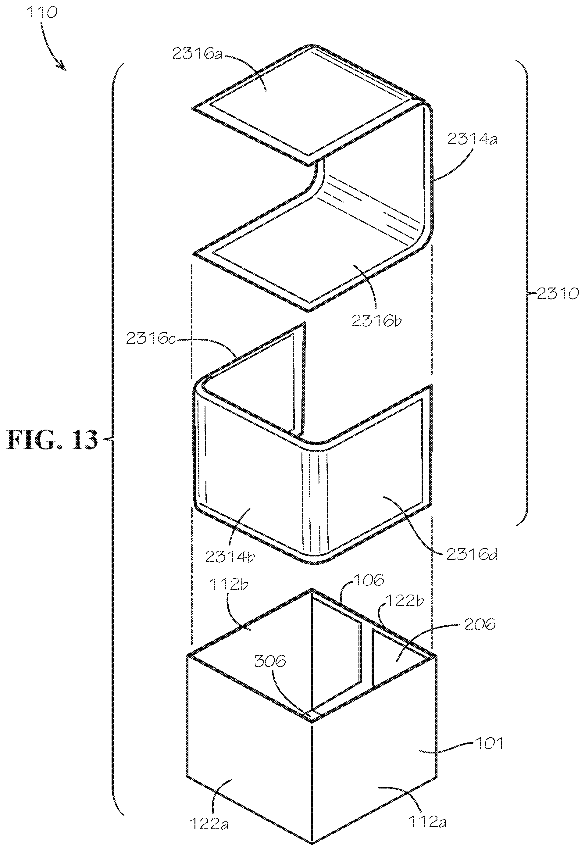
D00013
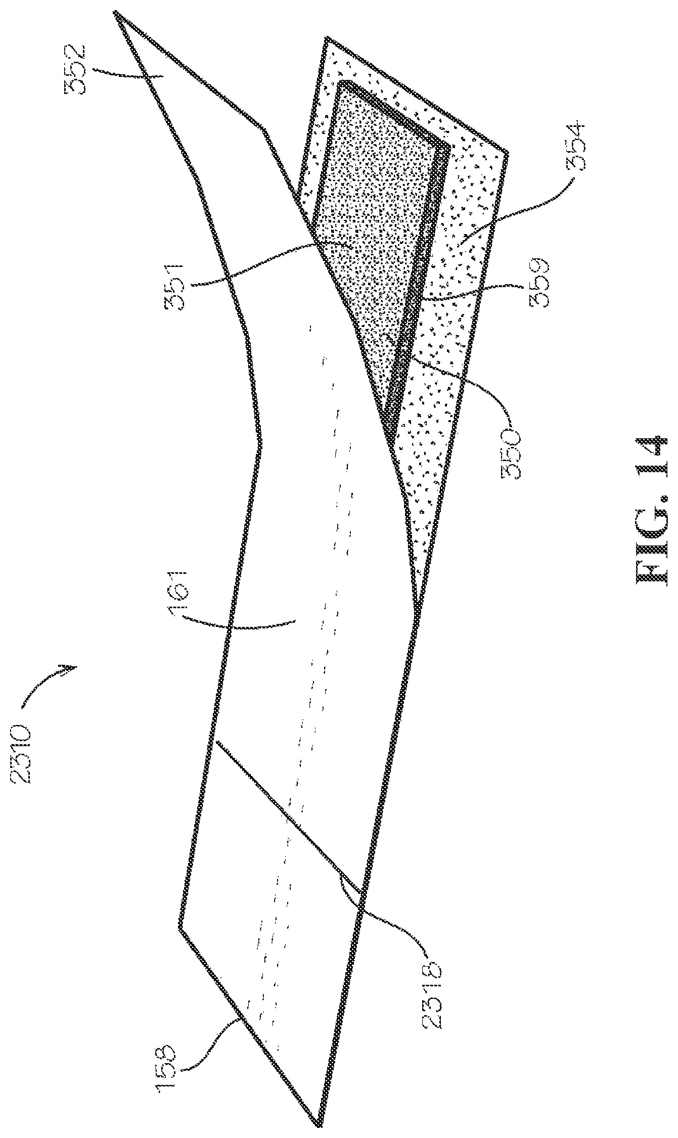
D00014

D00015

D00016
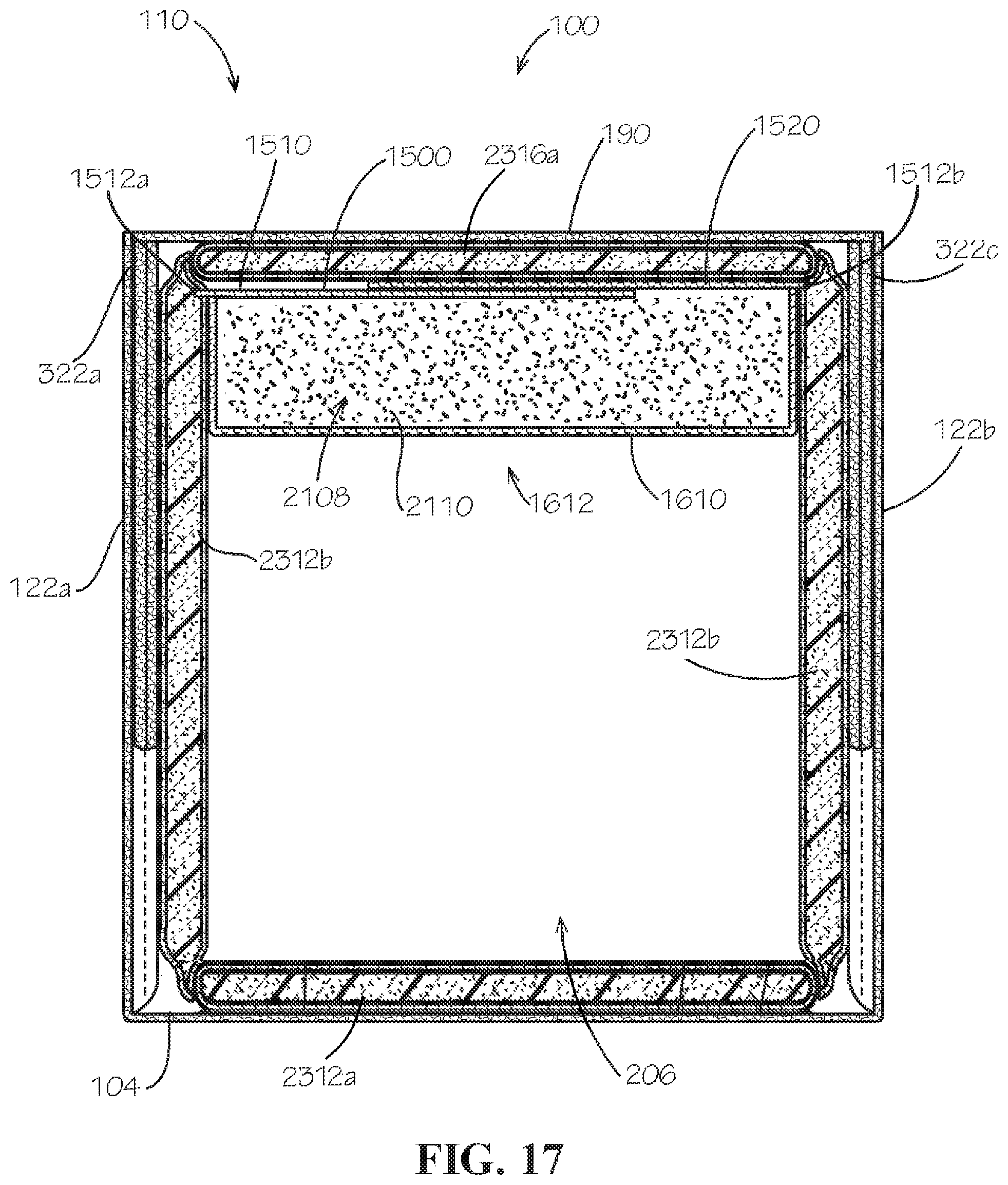
D00017

XML
uspto.report is an independent third-party trademark research tool that is not affiliated, endorsed, or sponsored by the United States Patent and Trademark Office (USPTO) or any other governmental organization. The information provided by uspto.report is based on publicly available data at the time of writing and is intended for informational purposes only.
While we strive to provide accurate and up-to-date information, we do not guarantee the accuracy, completeness, reliability, or suitability of the information displayed on this site. The use of this site is at your own risk. Any reliance you place on such information is therefore strictly at your own risk.
All official trademark data, including owner information, should be verified by visiting the official USPTO website at www.uspto.gov. This site is not intended to replace professional legal advice and should not be used as a substitute for consulting with a legal professional who is knowledgeable about trademark law.