LCP based predictive timing for cardiac resynchronization
Stahmann January 19, 2
U.S. patent number 10,894,163 [Application Number 15/805,239] was granted by the patent office on 2021-01-19 for lcp based predictive timing for cardiac resynchronization. This patent grant is currently assigned to CARDIAC PACEMAKERS, INC.. The grantee listed for this patent is CARDIAC PACEMAKERS, INC.. Invention is credited to Jeffrey E. Stahmann.


View All Diagrams
| United States Patent | 10,894,163 |
| Stahmann | January 19, 2021 |
LCP based predictive timing for cardiac resynchronization
Abstract
Methods, systems and devices for providing cardiac resynchronization therapy (CRT) to a patient using a leadless cardiac pacemaker (LCP) implanted in or proximate the left ventricle of a patient. A setup phase is used to establish parameters in the therapy delivery. In operation, the method and/or device will sense at least one non-paced cardiac cycle to determine a native R-R interval, and then delivers a synchronization pace at an interval less than the native R-R interval followed by a plurality of pace therapies delivered at the R-R interval or a modification thereof.
| Inventors: | Stahmann; Jeffrey E. (Ramsey, MN) | ||||||||||
|---|---|---|---|---|---|---|---|---|---|---|---|
| Applicant: |
|
||||||||||
| Assignee: | CARDIAC PACEMAKERS, INC. (St.
Paul, MN) |
||||||||||
| Appl. No.: | 15/805,239 | ||||||||||
| Filed: | November 7, 2017 |
Prior Publication Data
| Document Identifier | Publication Date | |
|---|---|---|
| US 20180140848 A1 | May 24, 2018 | |
Related U.S. Patent Documents
| Application Number | Filing Date | Patent Number | Issue Date | ||
|---|---|---|---|---|---|
| 62424582 | Nov 21, 2016 | ||||
| Current U.S. Class: | 1/1 |
| Current CPC Class: | A61N 1/3756 (20130101); A61N 1/3682 (20130101); A61N 1/37235 (20130101); A61N 1/0587 (20130101); A61N 1/37512 (20170801); A61N 1/3622 (20130101); A61N 1/3627 (20130101); A61N 1/37288 (20130101); A61N 1/36585 (20130101); A61N 1/36507 (20130101) |
| Current International Class: | A61N 1/36 (20060101); A61N 1/05 (20060101); A61N 1/375 (20060101); A61N 1/365 (20060101); A61N 1/368 (20060101); A61N 1/362 (20060101); A61N 1/372 (20060101) |
References Cited [Referenced By]
U.S. Patent Documents
| 3835864 | September 1974 | Rasor et al. |
| 3943936 | March 1976 | Rasor et al. |
| 4142530 | March 1979 | Wittkampf |
| 4151513 | April 1979 | Menken et al. |
| 4157720 | June 1979 | Greatbatch |
| RE30366 | August 1980 | Rasor et al. |
| 4243045 | January 1981 | Maas |
| 4250884 | February 1981 | Hartlaub et al. |
| 4256115 | March 1981 | Bilitch |
| 4263919 | April 1981 | Levin |
| 4310000 | January 1982 | Lindemans |
| 4312354 | January 1982 | Walters |
| 4323081 | April 1982 | Wiebusch |
| 4357946 | November 1982 | Dutcher et al. |
| 4365639 | December 1982 | Goldreyer |
| 4440173 | April 1984 | Hudziak et al. |
| 4476868 | October 1984 | Thompson |
| 4522208 | June 1985 | Buffet |
| 4537200 | August 1985 | Widrow |
| 4556063 | December 1985 | Thompson et al. |
| 4562841 | January 1986 | Brockway et al. |
| 4593702 | June 1986 | Kepski et al. |
| 4593955 | June 1986 | Leiber |
| 4630611 | December 1986 | King |
| 4635639 | January 1987 | Hakala et al. |
| 4674508 | June 1987 | DeCote |
| 4712554 | December 1987 | Garson |
| 4729376 | March 1988 | DeCote |
| 4754753 | July 1988 | King |
| 4759366 | July 1988 | Callaghan |
| 4776338 | October 1988 | Lekholm et al. |
| 4787389 | November 1988 | Tarjan |
| 4793353 | December 1988 | Borkan |
| 4819662 | April 1989 | Heil et al. |
| 4858610 | August 1989 | Callaghan et al. |
| 4886064 | December 1989 | Strandberg |
| 4887609 | December 1989 | Cole, Jr. |
| 4928688 | May 1990 | Mower |
| 4967746 | November 1990 | Vandegriff |
| 4987897 | January 1991 | Funke |
| 4989602 | February 1991 | Sholder et al. |
| 5012806 | May 1991 | De Bellis |
| 5036849 | August 1991 | Hauck et al. |
| 5040534 | August 1991 | Mann et al. |
| 5058581 | October 1991 | Silvian |
| 5078134 | January 1992 | Heilman et al. |
| 5109845 | May 1992 | Yuuchi et al. |
| 5113859 | May 1992 | Funke |
| 5113869 | May 1992 | Nappholz et al. |
| 5117824 | June 1992 | Keimel et al. |
| 5127401 | July 1992 | Grevious et al. |
| 5133353 | July 1992 | Hauser |
| 5144950 | September 1992 | Stoop et al. |
| 5170784 | December 1992 | Ramon et al. |
| 5179945 | January 1993 | Van Hofwegen et al. |
| 5193539 | March 1993 | Schulman et al. |
| 5193540 | March 1993 | Schulman et al. |
| 5241961 | September 1993 | Henry |
| 5243977 | September 1993 | Trabucco et al. |
| 5259387 | November 1993 | dePinto |
| 5269326 | December 1993 | Verrier |
| 5284136 | February 1994 | Hauck et al. |
| 5300107 | April 1994 | Stokes et al. |
| 5301677 | April 1994 | Hsung |
| 5305760 | April 1994 | McKown et al. |
| 5312439 | May 1994 | Loeb |
| 5313953 | May 1994 | Yomtov et al. |
| 5314459 | May 1994 | Swanson et al. |
| 5318597 | June 1994 | Hauck et al. |
| 5324316 | June 1994 | Schulman et al. |
| 5331966 | July 1994 | Bennett et al. |
| 5334222 | August 1994 | Salo et al. |
| 5342408 | August 1994 | deCoriolis et al. |
| 5370667 | December 1994 | Alt |
| 5372606 | December 1994 | Lang et al. |
| 5376106 | December 1994 | Stahmann et al. |
| 5383915 | January 1995 | Adams |
| 5388578 | February 1995 | Yomtov et al. |
| 5404877 | April 1995 | Nolan et al. |
| 5405367 | April 1995 | Schulman et al. |
| 5411031 | May 1995 | Yomtov |
| 5411525 | May 1995 | Swanson et al. |
| 5411535 | May 1995 | Fujii et al. |
| 5456691 | October 1995 | Snell |
| 5458622 | October 1995 | Alt |
| 5466246 | November 1995 | Silvian |
| 5468254 | November 1995 | Hahn et al. |
| 5472453 | December 1995 | Alt |
| 5522866 | June 1996 | Fernald |
| 5540727 | July 1996 | Tockman et al. |
| 5545186 | August 1996 | Olson et al. |
| 5545202 | August 1996 | Dahl et al. |
| 5571146 | November 1996 | Jones et al. |
| 5591214 | January 1997 | Lu |
| 5620466 | April 1997 | Haefner et al. |
| 5634938 | June 1997 | Swanson et al. |
| 5649968 | July 1997 | Alt et al. |
| 5662688 | September 1997 | Haefner et al. |
| 5674259 | October 1997 | Gray |
| 5683426 | November 1997 | Greenhut et al. |
| 5683432 | November 1997 | Goedeke et al. |
| 5702427 | December 1997 | Ecker et al. |
| 5706823 | January 1998 | Wodlinger |
| 5709215 | January 1998 | Perttu et al. |
| 5720770 | February 1998 | Nappholz et al. |
| 5728154 | March 1998 | Crossett et al. |
| 5741314 | April 1998 | Daly et al. |
| 5741315 | April 1998 | Lee et al. |
| 5752976 | May 1998 | Duffin et al. |
| 5752977 | May 1998 | Grevious et al. |
| 5755736 | May 1998 | Gillberg et al. |
| 5759199 | June 1998 | Snell et al. |
| 5774501 | June 1998 | Halpern et al. |
| 5792195 | August 1998 | Carlson et al. |
| 5792202 | August 1998 | Rueter |
| 5792203 | August 1998 | Schroeppel |
| 5792205 | August 1998 | Alt et al. |
| 5792208 | August 1998 | Gray |
| 5814089 | September 1998 | Stokes et al. |
| 5827216 | October 1998 | Igo et al. |
| 5836985 | November 1998 | Goyal et al. |
| 5836987 | November 1998 | Baumann et al. |
| 5842977 | December 1998 | Lesho et al. |
| 5855593 | January 1999 | Olson et al. |
| 5873894 | February 1999 | Vandegriff et al. |
| 5891184 | April 1999 | Lee et al. |
| 5897586 | April 1999 | Molina |
| 5899876 | May 1999 | Flower |
| 5899928 | May 1999 | Sholder et al. |
| 5919214 | July 1999 | Ciciarelli et al. |
| 5935078 | August 1999 | Feierbach |
| 5941906 | August 1999 | Barreras, Sr. et al. |
| 5944744 | August 1999 | Paul et al. |
| 5954757 | September 1999 | Gray |
| 5978713 | November 1999 | Prutchi et al. |
| 5991660 | November 1999 | Goyal |
| 5991661 | November 1999 | Park et al. |
| 5999848 | December 1999 | Gord et al. |
| 5999857 | December 1999 | Weijand et al. |
| 6016445 | January 2000 | Baura |
| 6026320 | February 2000 | Carlson et al. |
| 6029085 | February 2000 | Olson et al. |
| 6041250 | March 2000 | dePinto |
| 6044298 | March 2000 | Salo et al. |
| 6044300 | March 2000 | Gray |
| 6055454 | April 2000 | Heemels |
| 6073050 | June 2000 | Griffith |
| 6076016 | June 2000 | Feierbach |
| 6077236 | June 2000 | Cunningham |
| 6080187 | June 2000 | Alt et al. |
| 6083248 | July 2000 | Thompson |
| 6106551 | August 2000 | Crossett et al. |
| 6115636 | September 2000 | Ryan |
| 6128526 | October 2000 | Stadler et al. |
| 6141581 | October 2000 | Olson et al. |
| 6141588 | October 2000 | Cox et al. |
| 6141592 | October 2000 | Pauly |
| 6144879 | November 2000 | Gray |
| 6162195 | December 2000 | Igo et al. |
| 6164284 | December 2000 | Schulman et al. |
| 6167310 | December 2000 | Grevious |
| 6201993 | March 2001 | Kruse et al. |
| 6208894 | March 2001 | Schulman et al. |
| 6211799 | April 2001 | Post et al. |
| 6221011 | April 2001 | Bardy |
| 6240316 | May 2001 | Richmond et al. |
| 6240317 | May 2001 | Villaseca et al. |
| 6256534 | July 2001 | Dahl |
| 6259947 | July 2001 | Olson et al. |
| 6266558 | July 2001 | Gozani et al. |
| 6266567 | July 2001 | Ishikawa et al. |
| 6270457 | August 2001 | Bardy |
| 6272377 | August 2001 | Sweeney et al. |
| 6273856 | August 2001 | Sun et al. |
| 6277072 | August 2001 | Bardy |
| 6280380 | August 2001 | Bardy |
| 6285907 | September 2001 | Kramer et al. |
| 6292698 | September 2001 | Duffin et al. |
| 6295473 | September 2001 | Rosar |
| 6297943 | October 2001 | Carson |
| 6298271 | October 2001 | Weijand |
| 6307751 | October 2001 | Bodony et al. |
| 6312378 | November 2001 | Bardy |
| 6315721 | November 2001 | Schulman et al. |
| 6336903 | January 2002 | Bardy |
| 6345202 | February 2002 | Richmond et al. |
| 6351667 | February 2002 | Godie |
| 6351669 | February 2002 | Hartley et al. |
| 6353759 | March 2002 | Hartley et al. |
| 6358203 | March 2002 | Bardy |
| 6361780 | March 2002 | Ley et al. |
| 6368284 | April 2002 | Bardy |
| 6371922 | April 2002 | Baumann et al. |
| 6398728 | June 2002 | Bardy |
| 6400982 | June 2002 | Sweeney et al. |
| 6400990 | June 2002 | Silvian |
| 6408208 | June 2002 | Sun |
| 6409674 | June 2002 | Brockway et al. |
| 6411848 | June 2002 | Kramer et al. |
| 6424865 | July 2002 | Ding |
| 6434429 | August 2002 | Kraus et al. |
| 6438410 | August 2002 | Hsu et al. |
| 6438417 | August 2002 | Rockwell et al. |
| 6438421 | August 2002 | Stahmann et al. |
| 6440066 | August 2002 | Bardy |
| 6441747 | August 2002 | Khair et al. |
| 6442426 | August 2002 | Kroll |
| 6442432 | August 2002 | Lee |
| 6443891 | September 2002 | Grevious |
| 6445953 | September 2002 | Bulkes et al. |
| 6453200 | September 2002 | Koslar |
| 6459929 | October 2002 | Hopper et al. |
| 6470215 | October 2002 | Kraus et al. |
| 6471645 | October 2002 | Warkentin et al. |
| 6480745 | November 2002 | Nelson et al. |
| 6487443 | November 2002 | Olson et al. |
| 6490487 | December 2002 | Kraus et al. |
| 6498951 | December 2002 | Larson et al. |
| 6505077 | January 2003 | Kast et al. |
| 6507755 | January 2003 | Gozani et al. |
| 6507759 | January 2003 | Prutchi et al. |
| 6512940 | January 2003 | Brabec et al. |
| 6522915 | February 2003 | Ceballos et al. |
| 6526311 | February 2003 | Begemann |
| 6539253 | March 2003 | Thompson et al. |
| 6542775 | April 2003 | Ding et al. |
| 6553258 | April 2003 | Stahmann et al. |
| 6561975 | May 2003 | Pool et al. |
| 6564807 | May 2003 | Schulman et al. |
| 6574506 | June 2003 | Kramer et al. |
| 6584351 | June 2003 | Ekwall |
| 6584352 | June 2003 | Combs et al. |
| 6597948 | July 2003 | Rockwell et al. |
| 6597951 | July 2003 | Kramer et al. |
| 6622046 | September 2003 | Fraley et al. |
| 6628985 | September 2003 | Sweeney et al. |
| 6647292 | November 2003 | Bardy et al. |
| 6666844 | December 2003 | Igo et al. |
| 6689117 | February 2004 | Sweeney et al. |
| 6690959 | February 2004 | Thompson |
| 6694189 | February 2004 | Begemann |
| 6704602 | March 2004 | Berg et al. |
| 6718212 | April 2004 | Parry et al. |
| 6721597 | April 2004 | Bardy et al. |
| 6738670 | May 2004 | Almendinger et al. |
| 6746797 | June 2004 | Benson et al. |
| 6749566 | June 2004 | Russ |
| 6758810 | July 2004 | Lebel et al. |
| 6763269 | July 2004 | Cox |
| 6778860 | August 2004 | Ostroff et al. |
| 6788971 | September 2004 | Sloman et al. |
| 6788974 | September 2004 | Bardy et al. |
| 6804558 | October 2004 | Haller et al. |
| 6807442 | October 2004 | Myklebust et al. |
| 6847844 | January 2005 | Sun et al. |
| 6871095 | March 2005 | Stahmann et al. |
| 6878112 | April 2005 | Linberg et al. |
| 6885889 | April 2005 | Chinchoy |
| 6892094 | May 2005 | Ousdigian et al. |
| 6897788 | May 2005 | Khair et al. |
| 6904315 | June 2005 | Panken et al. |
| 6922592 | July 2005 | Thompson et al. |
| 6931282 | August 2005 | Esler |
| 6934585 | August 2005 | Schloss et al. |
| 6957107 | October 2005 | Rogers et al. |
| 6978176 | December 2005 | Lattouf |
| 6985773 | January 2006 | Von Arx et al. |
| 6990375 | January 2006 | Kloss et al. |
| 7001366 | February 2006 | Ballard |
| 7003350 | February 2006 | Denker et al. |
| 7006864 | February 2006 | Echt et al. |
| 7013178 | March 2006 | Reinke et al. |
| 7027871 | April 2006 | Burnes et al. |
| 7050849 | May 2006 | Echt et al. |
| 7060031 | June 2006 | Webb et al. |
| 7063693 | June 2006 | Guenst |
| 7082336 | July 2006 | Ransbury et al. |
| 7085606 | August 2006 | Flach et al. |
| 7092758 | August 2006 | Sun et al. |
| 7110824 | September 2006 | Amundson et al. |
| 7120504 | October 2006 | Osypka |
| 7130681 | October 2006 | Gebhardt et al. |
| 7139613 | November 2006 | Reinke et al. |
| 7142912 | November 2006 | Wagner et al. |
| 7146225 | December 2006 | Guenst et al. |
| 7146226 | December 2006 | Lau et al. |
| 7149575 | December 2006 | Ostroff et al. |
| 7149581 | December 2006 | Goedeke |
| 7149588 | December 2006 | Lau et al. |
| 7158839 | January 2007 | Lau |
| 7162307 | January 2007 | Patrias |
| 7164952 | January 2007 | Lau et al. |
| 7177700 | February 2007 | Cox |
| 7181505 | February 2007 | Haller et al. |
| 7184830 | February 2007 | Echt et al. |
| 7186214 | March 2007 | Ness |
| 7189204 | March 2007 | Ni et al. |
| 7191015 | March 2007 | Lamson et al. |
| 7200437 | April 2007 | Nabutovsky et al. |
| 7200439 | April 2007 | Zdeblick et al. |
| 7206423 | April 2007 | Feng et al. |
| 7209785 | April 2007 | Kim et al. |
| 7209790 | April 2007 | Thompson et al. |
| 7211884 | May 2007 | Davis et al. |
| 7212871 | May 2007 | Morgan |
| 7226440 | June 2007 | Gelfand et al. |
| 7228183 | June 2007 | Sun et al. |
| 7236821 | June 2007 | Cates et al. |
| 7236829 | June 2007 | Farazi et al. |
| 7254448 | August 2007 | Almendinger et al. |
| 7260436 | August 2007 | Kilgore et al. |
| 7270669 | September 2007 | Sra |
| 7272448 | September 2007 | Morgan et al. |
| 7277755 | October 2007 | Falkenberg et al. |
| 7280872 | October 2007 | Mosesov et al. |
| 7288096 | October 2007 | Chin |
| 7289847 | October 2007 | Gill et al. |
| 7289852 | October 2007 | Helfinstine et al. |
| 7289853 | October 2007 | Campbell et al. |
| 7289855 | October 2007 | Nghiem et al. |
| 7302294 | November 2007 | Kamath et al. |
| 7305266 | December 2007 | Kroll |
| 7310556 | December 2007 | Bulkes |
| 7319905 | January 2008 | Morgan et al. |
| 7333853 | February 2008 | Mazar et al. |
| 7336994 | February 2008 | Hettrick et al. |
| 7347819 | March 2008 | Lebel et al. |
| 7366572 | April 2008 | Heruth et al. |
| 7373207 | May 2008 | Lattouf |
| 7376458 | May 2008 | Palreddy et al. |
| 7384403 | June 2008 | Sherman |
| 7386342 | June 2008 | Falkenberg et al. |
| 7392090 | June 2008 | Sweeney et al. |
| 7406105 | July 2008 | DelMain et al. |
| 7406349 | July 2008 | Seeberger et al. |
| 7410497 | August 2008 | Hastings et al. |
| 7425200 | September 2008 | Brockway et al. |
| 7433739 | October 2008 | Salys et al. |
| 7477935 | January 2009 | Palreddy et al. |
| 7496409 | February 2009 | Greenhut et al. |
| 7496410 | February 2009 | Heil |
| 7502652 | March 2009 | Gaunt et al. |
| 7512448 | March 2009 | Malick et al. |
| 7515969 | April 2009 | Tockman et al. |
| 7526342 | April 2009 | Chin et al. |
| 7529589 | May 2009 | Williams et al. |
| 7532933 | May 2009 | Hastings et al. |
| 7536222 | May 2009 | Bardy et al. |
| 7536224 | May 2009 | Ritscher et al. |
| 7539541 | May 2009 | Quiles et al. |
| 7544197 | June 2009 | Kelsch et al. |
| 7558631 | July 2009 | Cowan et al. |
| 7565195 | July 2009 | Kroll et al. |
| 7584002 | September 2009 | Burnes et al. |
| 7590455 | September 2009 | Heruth et al. |
| 7606621 | October 2009 | Brisken et al. |
| 7610088 | October 2009 | Chinchoy |
| 7610092 | October 2009 | Cowan et al. |
| 7610099 | October 2009 | Almendinger et al. |
| 7610104 | October 2009 | Kaplan et al. |
| 7616991 | November 2009 | Mann et al. |
| 7617001 | November 2009 | Penner et al. |
| 7617007 | November 2009 | Williams et al. |
| 7630767 | December 2009 | Poore et al. |
| 7634313 | December 2009 | Kroll et al. |
| 7637867 | December 2009 | Zdeblick |
| 7640060 | December 2009 | Zdeblick |
| 7647109 | January 2010 | Hastings et al. |
| 7650186 | January 2010 | Hastings et al. |
| 7657311 | February 2010 | Bardy et al. |
| 7668596 | February 2010 | Von Arx et al. |
| 7682316 | March 2010 | Anderson et al. |
| 7691047 | April 2010 | Ferrari |
| 7702392 | April 2010 | Echt et al. |
| 7713194 | May 2010 | Zdeblick |
| 7713195 | May 2010 | Zdeblick |
| 7729783 | June 2010 | Michels et al. |
| 7734333 | June 2010 | Ghanem et al. |
| 7734343 | June 2010 | Ransbury et al. |
| 7738958 | June 2010 | Zdeblick et al. |
| 7738964 | June 2010 | Von Arx et al. |
| 7742812 | June 2010 | Ghanem et al. |
| 7742816 | June 2010 | Masoud et al. |
| 7742822 | June 2010 | Masoud et al. |
| 7743151 | June 2010 | Vallapureddy et al. |
| 7747335 | June 2010 | Williams |
| 7751881 | July 2010 | Cowan et al. |
| 7758521 | July 2010 | Morris et al. |
| 7761150 | July 2010 | Ghanem et al. |
| 7761164 | July 2010 | Verhoef et al. |
| 7765001 | July 2010 | Echt et al. |
| 7769452 | August 2010 | Ghanem et al. |
| 7783340 | August 2010 | Sanghera et al. |
| 7783362 | August 2010 | Whitehurst et al. |
| 7792588 | September 2010 | Harding |
| 7797059 | September 2010 | Bornzin et al. |
| 7801596 | September 2010 | Fischell et al. |
| 7809438 | October 2010 | Echt et al. |
| 7809441 | October 2010 | Kane et al. |
| 7840281 | November 2010 | Kveen et al. |
| 7844331 | November 2010 | Li et al. |
| 7844348 | November 2010 | Swoyer et al. |
| 7846088 | December 2010 | Ness |
| 7848815 | December 2010 | Brisken et al. |
| 7848823 | December 2010 | Drasler et al. |
| 7860455 | December 2010 | Fukumoto et al. |
| 7871433 | January 2011 | Lattouf |
| 7877136 | January 2011 | Moffitt et al. |
| 7877142 | January 2011 | Moaddeb et al. |
| 7881786 | February 2011 | Jackson |
| 7881798 | February 2011 | Miesel et al. |
| 7881810 | February 2011 | Chitre et al. |
| 7890173 | February 2011 | Brisken et al. |
| 7890181 | February 2011 | Denzene et al. |
| 7890192 | February 2011 | Kelsch et al. |
| 7894885 | February 2011 | Bartal et al. |
| 7894894 | February 2011 | Stadler et al. |
| 7894907 | February 2011 | Cowan et al. |
| 7894910 | February 2011 | Cowan et al. |
| 7894915 | February 2011 | Chitre et al. |
| 7899537 | March 2011 | Kroll et al. |
| 7899541 | March 2011 | Cowan et al. |
| 7899542 | March 2011 | Cowan et al. |
| 7899554 | March 2011 | Williams et al. |
| 7901360 | March 2011 | Yang et al. |
| 7904170 | March 2011 | Harding |
| 7907993 | March 2011 | Ghanem et al. |
| 7920928 | April 2011 | Yang et al. |
| 7925343 | April 2011 | Min et al. |
| 7930022 | April 2011 | Zhang et al. |
| 7930040 | April 2011 | Kelsch et al. |
| 7937135 | May 2011 | Ghanem et al. |
| 7937148 | May 2011 | Jacobson |
| 7937161 | May 2011 | Hastings et al. |
| 7941214 | May 2011 | Kleckner et al. |
| 7945333 | May 2011 | Jacobson |
| 7946997 | May 2011 | Hubinette |
| 7949404 | May 2011 | Hill |
| 7949405 | May 2011 | Feher |
| 7953486 | May 2011 | Daum et al. |
| 7953493 | May 2011 | Fowler et al. |
| 7962202 | June 2011 | Bhunia |
| 7974702 | July 2011 | Fain et al. |
| 7979136 | July 2011 | Young et al. |
| 7983753 | July 2011 | Severin |
| 7991467 | August 2011 | Markowitz et al. |
| 7991471 | August 2011 | Ghanem et al. |
| 7996087 | August 2011 | Cowan et al. |
| 8000791 | August 2011 | Sunagawa et al. |
| 8000807 | August 2011 | Morris et al. |
| 8001975 | August 2011 | DiSilvestro et al. |
| 8002700 | August 2011 | Ferek-Petric et al. |
| 8010209 | August 2011 | Jacobson |
| 8019419 | September 2011 | Panescu et al. |
| 8019434 | September 2011 | Quiles et al. |
| 8027727 | September 2011 | Freeberg |
| 8027729 | September 2011 | Sunagawa et al. |
| 8032219 | October 2011 | Neumann et al. |
| 8036743 | October 2011 | Savage et al. |
| 8046080 | October 2011 | Von Arx et al. |
| 8050297 | November 2011 | DelMain et al. |
| 8050759 | November 2011 | Stegemann et al. |
| 8050774 | November 2011 | Kveen et al. |
| 8055345 | November 2011 | Li et al. |
| 8055350 | November 2011 | Roberts |
| 8060212 | November 2011 | Rios et al. |
| 8065018 | November 2011 | Haubrich et al. |
| 8073542 | December 2011 | Doerr |
| 8078278 | December 2011 | Penner |
| 8078283 | December 2011 | Cowan et al. |
| 8079959 | December 2011 | Sanghera et al. |
| 8095123 | January 2012 | Gray |
| 8102789 | January 2012 | Rosar et al. |
| 8103359 | January 2012 | Reddy |
| 8103361 | January 2012 | Moser |
| 8112148 | February 2012 | Giftakis et al. |
| 8114021 | February 2012 | Robertson et al. |
| 8116867 | February 2012 | Ostroff |
| 8121680 | February 2012 | Falkenberg et al. |
| 8123684 | February 2012 | Zdeblick |
| 8126545 | February 2012 | Flach et al. |
| 8131334 | March 2012 | Lu et al. |
| 8140161 | March 2012 | Willerton et al. |
| 8150521 | April 2012 | Crowley et al. |
| 8157813 | April 2012 | Ko et al. |
| 8160672 | April 2012 | Kim et al. |
| 8160700 | April 2012 | Ryu |
| 8160702 | April 2012 | Mann et al. |
| 8160704 | April 2012 | Freeberg |
| 8165694 | April 2012 | Carbanaru et al. |
| 8175715 | May 2012 | Cox |
| 8180451 | May 2012 | Hickman et al. |
| 8185213 | May 2012 | Kveen et al. |
| 8187161 | May 2012 | Li et al. |
| 8195293 | June 2012 | Limousin et al. |
| 8195308 | June 2012 | Frank et al. |
| 8200341 | June 2012 | Sanghera et al. |
| 8204595 | June 2012 | Pianca et al. |
| 8204605 | June 2012 | Hastings et al. |
| 8209014 | June 2012 | Doerr |
| 8214043 | July 2012 | Matos |
| 8224244 | July 2012 | Kim et al. |
| 8229556 | July 2012 | Li |
| 8233985 | July 2012 | Bulkes et al. |
| 8265748 | September 2012 | Liu et al. |
| 8265757 | September 2012 | Mass et al. |
| 8262578 | October 2012 | Bharmi et al. |
| 8280521 | October 2012 | Haubrich et al. |
| 8285387 | October 2012 | Utsi et al. |
| 8290598 | October 2012 | Boon et al. |
| 8290600 | October 2012 | Hastings et al. |
| 8295939 | October 2012 | Jacobson |
| 8301254 | October 2012 | Mosesov et al. |
| 8315701 | November 2012 | Cowan et al. |
| 8315708 | November 2012 | Berthelsdorf et al. |
| 8321021 | November 2012 | Kisker et al. |
| 8321036 | November 2012 | Brockway et al. |
| 8332034 | December 2012 | Patangay et al. |
| 8332036 | December 2012 | Hastings et al. |
| 8335563 | December 2012 | Stessman |
| 8335568 | December 2012 | Heruth et al. |
| 8340750 | December 2012 | Prakash et al. |
| 8340780 | December 2012 | Hastings et al. |
| 8352025 | January 2013 | Jacobson |
| 8352028 | January 2013 | Wenger |
| 8352038 | January 2013 | Mao et al. |
| 8359098 | January 2013 | Lund et al. |
| 8364261 | January 2013 | Stubbs et al. |
| 8364276 | January 2013 | Willis |
| 8369959 | February 2013 | Meskens |
| 8369962 | February 2013 | Abrahamson |
| 8380320 | February 2013 | Spital |
| 8386051 | February 2013 | Rys |
| 8391981 | March 2013 | Mosesov |
| 8391990 | March 2013 | Smith et al. |
| 8406874 | March 2013 | Liu et al. |
| 8406879 | March 2013 | Shuros et al. |
| 8406886 | March 2013 | Gaunt et al. |
| 8412352 | April 2013 | Griswold et al. |
| 8417340 | April 2013 | Goossen |
| 8417341 | April 2013 | Freeberg |
| 8423149 | April 2013 | Hennig |
| 8428722 | April 2013 | Verhoef et al. |
| 8433402 | April 2013 | Ruben et al. |
| 8433409 | April 2013 | Johnson et al. |
| 8433420 | April 2013 | Bange et al. |
| 8447412 | May 2013 | Dal Molin et al. |
| 8452413 | May 2013 | Young et al. |
| 8457740 | June 2013 | Osche |
| 8457742 | June 2013 | Jacobson |
| 8457744 | June 2013 | Janzig et al. |
| 8457761 | June 2013 | Wariar |
| 8478399 | July 2013 | Degroot et al. |
| 8478407 | July 2013 | Demmer et al. |
| 8478408 | July 2013 | Hastings et al. |
| 8478431 | July 2013 | Griswold et al. |
| 8483843 | July 2013 | Sanghera et al. |
| 8494632 | July 2013 | Sun et al. |
| 8504156 | August 2013 | Bonner et al. |
| 8509910 | August 2013 | Sowder et al. |
| 8515559 | August 2013 | Roberts et al. |
| 8525340 | September 2013 | Eckhardt et al. |
| 8527068 | September 2013 | Ostroff |
| 8532790 | September 2013 | Griswold |
| 8538526 | September 2013 | Stahmann et al. |
| 8541131 | September 2013 | Lund et al. |
| 8543205 | September 2013 | Ostroff |
| 8547248 | October 2013 | Zdeblick et al. |
| 8548605 | October 2013 | Ollivier |
| 8554333 | October 2013 | Wu et al. |
| 8565878 | October 2013 | Allavatam et al. |
| 8565882 | October 2013 | Matos |
| 8565897 | October 2013 | Regnier et al. |
| 8571678 | October 2013 | Wang |
| 8577327 | November 2013 | Makdissi et al. |
| 8588926 | November 2013 | Moore et al. |
| 8612002 | December 2013 | Faltys et al. |
| 8615310 | December 2013 | Khairkhahan et al. |
| 8626280 | January 2014 | Allavatam et al. |
| 8626294 | January 2014 | Sheldon et al. |
| 8626310 | January 2014 | Barror et al. |
| 8634908 | January 2014 | Cowan |
| 8634912 | January 2014 | Bornzin et al. |
| 8634919 | January 2014 | Hou et al. |
| 8639335 | January 2014 | Peichel et al. |
| 8644934 | February 2014 | Hastings et al. |
| 8649859 | February 2014 | Smith et al. |
| 8670842 | March 2014 | Bornzin et al. |
| 8676319 | March 2014 | Knoll |
| 8676335 | March 2014 | Katoozi et al. |
| 8700173 | April 2014 | Edlund |
| 8700181 | April 2014 | Bornzin et al. |
| 8705599 | April 2014 | dal Molin et al. |
| 8718766 | May 2014 | Wahlberg |
| 8718773 | May 2014 | Willis et al. |
| 8725260 | May 2014 | Shuros et al. |
| 8738133 | May 2014 | Shuros et al. |
| 8738147 | May 2014 | Hastings et al. |
| 8744555 | June 2014 | Allavatam et al. |
| 8744572 | June 2014 | Greenhut et al. |
| 8747314 | June 2014 | Stahmann et al. |
| 8755884 | June 2014 | Demmer et al. |
| 8758365 | June 2014 | Bonner et al. |
| 8768483 | July 2014 | Schmitt et al. |
| 8774572 | July 2014 | Hamamoto |
| 8781605 | July 2014 | Bornzin et al. |
| 8788035 | July 2014 | Jacobson |
| 8788053 | July 2014 | Jacobson |
| 8798740 | August 2014 | Samade et al. |
| 8798745 | August 2014 | Jacobson |
| 8798762 | August 2014 | Fain et al. |
| 8798770 | August 2014 | Reddy |
| 8805505 | August 2014 | Roberts |
| 8805528 | August 2014 | Corndorf |
| 8812109 | August 2014 | Blomqvist et al. |
| 8818504 | August 2014 | Bodner et al. |
| 8827913 | September 2014 | Havel et al. |
| 8831747 | September 2014 | Min et al. |
| 8855789 | October 2014 | Jacobson |
| 8868186 | October 2014 | Kroll |
| 8886325 | November 2014 | Boling et al. |
| 8886339 | November 2014 | Faltys et al. |
| 8903473 | December 2014 | Rogers et al. |
| 8903500 | December 2014 | Smith et al. |
| 8903513 | December 2014 | Ollivier |
| 8909336 | December 2014 | Navarro-Paredes et al. |
| 8914131 | December 2014 | Bornzin et al. |
| 8923795 | December 2014 | Makdissi et al. |
| 8923963 | December 2014 | Bonner et al. |
| 8938300 | January 2015 | Rosero |
| 8942806 | January 2015 | Sheldon et al. |
| 8958892 | February 2015 | Khairkhahan et al. |
| 8977358 | March 2015 | Ewert et al. |
| 8989873 | March 2015 | Locsin |
| 8996109 | March 2015 | Karst et al. |
| 9002467 | April 2015 | Smith et al. |
| 9008776 | April 2015 | Cowan et al. |
| 9008777 | April 2015 | Dianaty et al. |
| 9014818 | April 2015 | Deterre et al. |
| 9017341 | April 2015 | Bornzin et al. |
| 9020611 | April 2015 | Khairkhahan et al. |
| 9037262 | May 2015 | Regnier et al. |
| 9042984 | May 2015 | Demmer et al. |
| 9072911 | July 2015 | Hastings et al. |
| 9072913 | July 2015 | Jacobson |
| 9072914 | July 2015 | Greenhut et al. |
| 9079035 | July 2015 | Sanghera et al. |
| 9155882 | October 2015 | Grubac et al. |
| 9168372 | October 2015 | Fain |
| 9168380 | October 2015 | Greenhut et al. |
| 9168383 | October 2015 | Jacobson et al. |
| 9180285 | November 2015 | Moore et al. |
| 9192774 | November 2015 | Jacobson |
| 9205225 | December 2015 | Khairkhahan et al. |
| 9216285 | December 2015 | Boling et al. |
| 9216293 | December 2015 | Berthiaume et al. |
| 9216298 | December 2015 | Jacobson |
| 9227077 | January 2016 | Jacobson |
| 9238145 | January 2016 | Wenzel et al. |
| 9242102 | January 2016 | Khairkhahan et al. |
| 9242113 | January 2016 | Smith et al. |
| 9248300 | February 2016 | Rys et al. |
| 9265436 | February 2016 | Min et al. |
| 9265962 | February 2016 | Dianaty et al. |
| 9272155 | March 2016 | Ostroff |
| 9278218 | March 2016 | Karst et al. |
| 9278229 | March 2016 | Reinke et al. |
| 9283381 | March 2016 | Grubac et al. |
| 9283382 | March 2016 | Berthiaume et al. |
| 9289612 | March 2016 | Sambelashvili et al. |
| 9302115 | April 2016 | Molin et al. |
| 9333364 | May 2016 | Echt et al. |
| 9358387 | June 2016 | Suwito et al. |
| 9358400 | June 2016 | Jacobson |
| 9364675 | June 2016 | Deterre et al. |
| 9370663 | June 2016 | Moulder |
| 9375580 | June 2016 | Bonner et al. |
| 9375581 | June 2016 | Baru et al. |
| 9381365 | July 2016 | Kibler et al. |
| 9393424 | July 2016 | Demmer et al. |
| 9393436 | July 2016 | Doerr |
| 9399139 | July 2016 | Demmer et al. |
| 9399140 | July 2016 | Cho et al. |
| 9409033 | August 2016 | Jacobson |
| 9427594 | August 2016 | Bornzin et al. |
| 9433368 | September 2016 | Stahmann et al. |
| 9433780 | September 2016 | Regnier et al. |
| 9457193 | October 2016 | Klimovitch et al. |
| 9492668 | November 2016 | Sheldon et al. |
| 9492669 | November 2016 | Demmer et al. |
| 9492674 | November 2016 | Schmidt et al. |
| 9492677 | November 2016 | Greenhut et al. |
| 9511233 | December 2016 | Sambelashvili |
| 9511236 | December 2016 | Varady et al. |
| 9511237 | December 2016 | Deterre et al. |
| 9522276 | December 2016 | Shen et al. |
| 9522280 | December 2016 | Fishler et al. |
| 9526522 | December 2016 | Wood et al. |
| 9526891 | December 2016 | Eggen et al. |
| 9526909 | December 2016 | Stahmann et al. |
| 9533163 | January 2017 | Klimovitch et al. |
| 9561382 | February 2017 | Persson et al. |
| 9566012 | February 2017 | Greenhut et al. |
| 9636511 | May 2017 | Carney et al. |
| 9669223 | June 2017 | Auricchio et al. |
| 9687654 | June 2017 | Sheldon et al. |
| 9687655 | June 2017 | Pertijs et al. |
| 9687659 | June 2017 | Von Arx et al. |
| 9694186 | July 2017 | Carney et al. |
| 9782594 | October 2017 | Stahmann et al. |
| 9782601 | October 2017 | Ludwig |
| 9789317 | October 2017 | Greenhut et al. |
| 9789319 | October 2017 | Sambelashvili |
| 9808617 | November 2017 | Ostroff et al. |
| 9808628 | November 2017 | Sheldon et al. |
| 9808631 | November 2017 | Maile et al. |
| 9808632 | November 2017 | Reinke et al. |
| 9808633 | November 2017 | Bonner et al. |
| 9808637 | November 2017 | Sharma et al. |
| 9855414 | January 2018 | Marshall et al. |
| 9855430 | January 2018 | Ghosh et al. |
| 9855435 | January 2018 | Sahabi et al. |
| 9861815 | January 2018 | Tran et al. |
| 2002/0032470 | March 2002 | Linberg |
| 2002/0035376 | March 2002 | Bardy et al. |
| 2002/0035377 | March 2002 | Bardy et al. |
| 2002/0035378 | March 2002 | Bardy et al. |
| 2002/0035380 | March 2002 | Rissmann et al. |
| 2002/0035381 | March 2002 | Bardy et al. |
| 2002/0042629 | April 2002 | Bardy et al. |
| 2002/0042630 | April 2002 | Bardy et al. |
| 2002/0042634 | April 2002 | Bardy et al. |
| 2002/0049475 | April 2002 | Bardy et al. |
| 2002/0052636 | May 2002 | Bardy et al. |
| 2002/0068958 | June 2002 | Bardy et al. |
| 2002/0072773 | June 2002 | Bardy et al. |
| 2002/0082665 | June 2002 | Haller et al. |
| 2002/0091414 | July 2002 | Bardy et al. |
| 2002/0095196 | July 2002 | Linberg |
| 2002/0099423 | July 2002 | Berg et al. |
| 2002/0103510 | August 2002 | Bardy et al. |
| 2002/0107545 | August 2002 | Rissmann et al. |
| 2002/0107546 | August 2002 | Ostroff et al. |
| 2002/0107547 | August 2002 | Erlinger et al. |
| 2002/0107548 | August 2002 | Bardy et al. |
| 2002/0107549 | August 2002 | Bardy et al. |
| 2002/0107559 | August 2002 | Sanders et al. |
| 2002/0120299 | August 2002 | Ostroff et al. |
| 2002/0173830 | November 2002 | Starkweather et al. |
| 2002/0193846 | December 2002 | Pool et al. |
| 2003/0009203 | January 2003 | Lebel et al. |
| 2003/0028082 | February 2003 | Thompson |
| 2003/0040779 | February 2003 | Engmark et al. |
| 2003/0041866 | March 2003 | Linberg et al. |
| 2003/0045805 | March 2003 | Sheldon et al. |
| 2003/0088278 | May 2003 | Bardy et al. |
| 2003/0097153 | May 2003 | Bardy et al. |
| 2003/0105497 | June 2003 | Zhu et al. |
| 2003/0114908 | June 2003 | Flach |
| 2003/0135242 | July 2003 | Mongeon |
| 2003/0144701 | July 2003 | Mehra et al. |
| 2003/0187460 | October 2003 | Chin et al. |
| 2003/0187461 | October 2003 | Chin |
| 2004/0024435 | February 2004 | Leckrone et al. |
| 2004/0068302 | April 2004 | Rodgers et al. |
| 2004/0087938 | May 2004 | Leckrone et al. |
| 2004/0088035 | May 2004 | Guenst et al. |
| 2004/0102830 | May 2004 | Williams |
| 2004/0127959 | July 2004 | Amundson et al. |
| 2004/0133242 | July 2004 | Chapman et al. |
| 2004/0147969 | July 2004 | Mann et al. |
| 2004/0147973 | July 2004 | Hauser |
| 2004/0167558 | August 2004 | Igo et al. |
| 2004/0167587 | August 2004 | Thompson |
| 2004/0172071 | September 2004 | Bardy et al. |
| 2004/0172077 | September 2004 | Chinchoy |
| 2004/0172104 | September 2004 | Berg et al. |
| 2004/0176817 | September 2004 | Wahlstrand et al. |
| 2004/0176818 | September 2004 | Wahlstrand et al. |
| 2004/0176830 | September 2004 | Fang |
| 2004/0186529 | September 2004 | Bardy et al. |
| 2004/0204673 | October 2004 | Flaherty |
| 2004/0210292 | October 2004 | Bardy et al. |
| 2004/0210293 | October 2004 | Bardy et al. |
| 2004/0210294 | October 2004 | Bardy et al. |
| 2004/0215308 | October 2004 | Bardy et al. |
| 2004/0220624 | November 2004 | Ritscher et al. |
| 2004/0220626 | November 2004 | Wagner |
| 2004/0220639 | November 2004 | Mulligan et al. |
| 2004/0249431 | December 2004 | Ransbury et al. |
| 2004/0260348 | December 2004 | Bakken et al. |
| 2004/0267303 | December 2004 | Guenst |
| 2005/0061320 | March 2005 | Lee et al. |
| 2005/0070962 | March 2005 | Echt et al. |
| 2005/0102003 | May 2005 | Grabek et al. |
| 2005/0149138 | July 2005 | Min et al. |
| 2005/0165466 | July 2005 | Morris et al. |
| 2005/0182465 | August 2005 | Ness |
| 2005/0203410 | September 2005 | Jenkins |
| 2005/0283208 | December 2005 | Arx et al. |
| 2005/0288743 | December 2005 | Ahn et al. |
| 2006/0042830 | March 2006 | Maghribi et al. |
| 2006/0052829 | March 2006 | Sun et al. |
| 2006/0052830 | March 2006 | Spinelli et al. |
| 2006/0064135 | March 2006 | Brockway |
| 2006/0064149 | March 2006 | Belacazar et al. |
| 2006/0085039 | April 2006 | Hastings et al. |
| 2006/0085041 | April 2006 | Hastings et al. |
| 2006/0085042 | April 2006 | Hastings et al. |
| 2006/0095078 | May 2006 | Tronnes |
| 2006/0106442 | May 2006 | Richardson et al. |
| 2006/0116746 | June 2006 | Chin |
| 2006/0135999 | June 2006 | Bodner et al. |
| 2006/0136004 | June 2006 | Cowan et al. |
| 2006/0161061 | July 2006 | Echt et al. |
| 2006/0200002 | September 2006 | Guenst |
| 2006/0206151 | September 2006 | Lu |
| 2006/0212079 | September 2006 | Routh et al. |
| 2006/0241701 | October 2006 | Markowitz et al. |
| 2006/0241705 | October 2006 | Neumann et al. |
| 2006/0247672 | November 2006 | Vidlund et al. |
| 2006/0259088 | November 2006 | Pastore et al. |
| 2006/0265018 | November 2006 | Smith et al. |
| 2007/0004979 | January 2007 | Wojciechowicz et al. |
| 2007/0016098 | January 2007 | Kim et al. |
| 2007/0027508 | February 2007 | Cowan |
| 2007/0078490 | April 2007 | Cowan et al. |
| 2007/0088394 | April 2007 | Jacobson |
| 2007/0088396 | April 2007 | Jacobson |
| 2007/0088397 | April 2007 | Jacobson |
| 2007/0088398 | April 2007 | Jacobson |
| 2007/0088405 | April 2007 | Jacobson |
| 2007/0135882 | June 2007 | Drasler et al. |
| 2007/0135883 | June 2007 | Drasler et al. |
| 2007/0150037 | June 2007 | Hastings et al. |
| 2007/0150038 | June 2007 | Hastings et al. |
| 2007/0156190 | July 2007 | Cinbis |
| 2007/0219525 | September 2007 | Gelfand et al. |
| 2007/0219590 | September 2007 | Hastings et al. |
| 2007/0225545 | September 2007 | Ferrari |
| 2007/0233206 | October 2007 | Frikart et al. |
| 2007/0239244 | October 2007 | Morgan et al. |
| 2007/0255376 | November 2007 | Michels et al. |
| 2007/0276444 | November 2007 | Gelbart et al. |
| 2007/0293900 | December 2007 | Sheldon et al. |
| 2007/0293904 | December 2007 | Gelbart et al. |
| 2008/0004663 | January 2008 | Jorgenson |
| 2008/0021505 | January 2008 | Hastings et al. |
| 2008/0021519 | January 2008 | De Geest et al. |
| 2008/0021532 | January 2008 | Kveen et al. |
| 2008/0065183 | March 2008 | Whitehurst et al. |
| 2008/0065185 | March 2008 | Worley |
| 2008/0071318 | March 2008 | Brooke et al. |
| 2008/0109054 | May 2008 | Hastings et al. |
| 2008/0119911 | May 2008 | Rosero |
| 2008/0130670 | June 2008 | Kim et al. |
| 2008/0154139 | June 2008 | Shuros et al. |
| 2008/0154322 | June 2008 | Jackson et al. |
| 2008/0228234 | September 2008 | Stancer |
| 2008/0234771 | September 2008 | Chinchoy et al. |
| 2008/0243217 | October 2008 | Wildon |
| 2008/0269814 | October 2008 | Rosero |
| 2008/0269825 | October 2008 | Chinchoy et al. |
| 2008/0275518 | November 2008 | Ghanem et al. |
| 2008/0275519 | November 2008 | Ghanem et al. |
| 2008/0275522 | November 2008 | Dong et al. |
| 2008/0288039 | November 2008 | Reddy |
| 2008/0294208 | November 2008 | Willis et al. |
| 2008/0294210 | November 2008 | Rosero |
| 2008/0306359 | December 2008 | Zdeblick et al. |
| 2009/0018599 | January 2009 | Hastings et al. |
| 2009/0024180 | January 2009 | Kisker et al. |
| 2009/0036941 | February 2009 | Corbucci |
| 2009/0048646 | February 2009 | Katoozi et al. |
| 2009/0062895 | March 2009 | Stahmann et al. |
| 2009/0082827 | March 2009 | Kveen et al. |
| 2009/0082828 | March 2009 | Ostroff |
| 2009/0088813 | April 2009 | Brockway et al. |
| 2009/0131907 | May 2009 | Chin et al. |
| 2009/0135886 | May 2009 | Robertson et al. |
| 2009/0143835 | June 2009 | Pastore et al. |
| 2009/0171408 | July 2009 | Solem |
| 2009/0171414 | July 2009 | Kelly et al. |
| 2009/0204163 | August 2009 | Shuros et al. |
| 2009/0204170 | August 2009 | Hastings et al. |
| 2009/0210024 | August 2009 | Brooke |
| 2009/0216292 | August 2009 | Pless et al. |
| 2009/0234407 | September 2009 | Hastings et al. |
| 2009/0234411 | September 2009 | Sambelashvili et al. |
| 2009/0264949 | October 2009 | Dong et al. |
| 2009/0266573 | October 2009 | Engmark et al. |
| 2009/0270937 | October 2009 | Yonce et al. |
| 2009/0275998 | November 2009 | Burnes et al. |
| 2009/0275999 | November 2009 | Burnes et al. |
| 2009/0299447 | December 2009 | Jensen et al. |
| 2010/0013668 | January 2010 | Kantervik |
| 2010/0016911 | January 2010 | Willis et al. |
| 2010/0023085 | January 2010 | Wu et al. |
| 2010/0030061 | February 2010 | Canfield et al. |
| 2010/0030327 | February 2010 | Chatel |
| 2010/0042108 | February 2010 | Hibino |
| 2010/0056871 | March 2010 | Govari et al. |
| 2010/0063375 | March 2010 | Kassab et al. |
| 2010/0063562 | March 2010 | Cowan et al. |
| 2010/0094367 | April 2010 | Sen |
| 2010/0094370 | April 2010 | Levin |
| 2010/0114209 | May 2010 | Krause et al. |
| 2010/0114214 | May 2010 | Morelli et al. |
| 2010/0125281 | May 2010 | Jacobson et al. |
| 2010/0168761 | July 2010 | Kassab et al. |
| 2010/0168819 | July 2010 | Freeberg |
| 2010/0198288 | August 2010 | Ostroff |
| 2010/0198304 | August 2010 | Wang |
| 2010/0217367 | August 2010 | Belson |
| 2010/0228308 | September 2010 | Cowan et al. |
| 2010/0234906 | September 2010 | Koh |
| 2010/0234924 | September 2010 | Willis |
| 2010/0241185 | September 2010 | Mahapatra et al. |
| 2010/0249729 | September 2010 | Morris et al. |
| 2010/0286744 | November 2010 | Echt et al. |
| 2010/0305646 | December 2010 | Schulte et al. |
| 2010/0312309 | December 2010 | Harding |
| 2010/0331905 | December 2010 | Li et al. |
| 2011/0022113 | January 2011 | Zdeblick et al. |
| 2011/0071586 | March 2011 | Jacobson |
| 2011/0077708 | March 2011 | Ostroff |
| 2011/0112600 | May 2011 | Cowan et al. |
| 2011/0118588 | May 2011 | Komblau et al. |
| 2011/0118810 | May 2011 | Cowan et al. |
| 2011/0137187 | June 2011 | Yang et al. |
| 2011/0144720 | June 2011 | Cowan et al. |
| 2011/0152970 | June 2011 | Jollota et al. |
| 2011/0160558 | June 2011 | Rassatt et al. |
| 2011/0160565 | June 2011 | Stubbs et al. |
| 2011/0160801 | June 2011 | Markowitz et al. |
| 2011/0160806 | June 2011 | Lyden et al. |
| 2011/0166620 | July 2011 | Cowan et al. |
| 2011/0166621 | July 2011 | Cowan et al. |
| 2011/0178567 | July 2011 | Pei et al. |
| 2011/0184491 | July 2011 | Kivi |
| 2011/0190835 | August 2011 | Brockway et al. |
| 2011/0208260 | August 2011 | Jacobson |
| 2011/0218587 | September 2011 | Jacobson |
| 2011/0230734 | September 2011 | Fain et al. |
| 2011/0237967 | September 2011 | Moore et al. |
| 2011/0245890 | October 2011 | Brisben et al. |
| 2011/0251660 | October 2011 | Griswold |
| 2011/0251662 | October 2011 | Griswold et al. |
| 2011/0270099 | November 2011 | Ruben et al. |
| 2011/0270339 | November 2011 | Murray, III et al. |
| 2011/0270340 | November 2011 | Pellegrini et al. |
| 2011/0276102 | November 2011 | Cohen |
| 2011/0282423 | November 2011 | Jacobson |
| 2012/0004527 | January 2012 | Thompson et al. |
| 2012/0029323 | February 2012 | Zhao |
| 2012/0029335 | February 2012 | Sudam et al. |
| 2012/0041508 | February 2012 | Rousso et al. |
| 2012/0059433 | March 2012 | Cowan et al. |
| 2012/0059436 | March 2012 | Fontaine et al. |
| 2012/0065500 | March 2012 | Rogers et al. |
| 2012/0078322 | March 2012 | Molin et al. |
| 2012/0089198 | April 2012 | Ostroff |
| 2012/0093245 | April 2012 | Makdissi et al. |
| 2012/0095521 | April 2012 | Hintz |
| 2012/0095539 | April 2012 | Khairkhahan et al. |
| 2012/0101540 | April 2012 | O'Brien et al. |
| 2012/0101553 | April 2012 | Reddy |
| 2012/0109148 | May 2012 | Bonner et al. |
| 2012/0109149 | May 2012 | Bonner et al. |
| 2012/0109236 | May 2012 | Jacobson et al. |
| 2012/0109259 | May 2012 | Bond et al. |
| 2012/0116489 | May 2012 | Khairkhahan et al. |
| 2012/0150251 | June 2012 | Giftakis et al. |
| 2012/0158111 | June 2012 | Khairkhahan et al. |
| 2012/0165827 | June 2012 | Khairkhahan et al. |
| 2012/0172690 | July 2012 | Anderson et al. |
| 2012/0172891 | July 2012 | Lee |
| 2012/0172892 | July 2012 | Grubac et al. |
| 2012/0172942 | July 2012 | Berg |
| 2012/0185007 | July 2012 | Ziegler |
| 2012/0197350 | August 2012 | Roberts et al. |
| 2012/0197373 | August 2012 | Khairkhahan et al. |
| 2012/0215285 | August 2012 | Tahmasian et al. |
| 2012/0232565 | September 2012 | Kveen et al. |
| 2012/0277600 | November 2012 | Greenhut |
| 2012/0277606 | November 2012 | Ellingson et al. |
| 2012/0283795 | November 2012 | Stancer et al. |
| 2012/0283807 | November 2012 | Deterre et al. |
| 2012/0290025 | November 2012 | Keimel |
| 2012/0296381 | November 2012 | Matos |
| 2012/0303082 | November 2012 | Dong et al. |
| 2012/0316613 | December 2012 | Keefe et al. |
| 2013/0012151 | January 2013 | Hankins |
| 2013/0023975 | January 2013 | Locsin |
| 2013/0030484 | January 2013 | Zhang et al. |
| 2013/0035748 | February 2013 | Bonner et al. |
| 2013/0041422 | February 2013 | Jacobson |
| 2013/0053908 | February 2013 | Smith et al. |
| 2013/0053915 | February 2013 | Holmstrom et al. |
| 2013/0053921 | February 2013 | Bonner et al. |
| 2013/0060298 | March 2013 | Splett et al. |
| 2013/0066169 | March 2013 | Rys et al. |
| 2013/0072770 | March 2013 | Rao et al. |
| 2013/0079798 | March 2013 | Tran et al. |
| 2013/0079861 | March 2013 | Reinert et al. |
| 2013/0085350 | April 2013 | Schugt et al. |
| 2013/0085403 | April 2013 | Gunderson et al. |
| 2013/0085550 | April 2013 | Polefko et al. |
| 2013/0096649 | April 2013 | Martin et al. |
| 2013/0103047 | April 2013 | Steingisser et al. |
| 2013/0103109 | April 2013 | Jacobson |
| 2013/0110008 | May 2013 | Bourget et al. |
| 2013/0110127 | May 2013 | Bornzin et al. |
| 2013/0110192 | May 2013 | Tran et al. |
| 2013/0110219 | May 2013 | Bornzin et al. |
| 2013/0116529 | May 2013 | Min et al. |
| 2013/0116738 | May 2013 | Samade et al. |
| 2013/0116740 | May 2013 | Bornzin et al. |
| 2013/0116741 | May 2013 | Bornzin et al. |
| 2013/0123872 | May 2013 | Bornzin et al. |
| 2013/0123875 | May 2013 | Varady et al. |
| 2013/0131591 | May 2013 | Berthiaume et al. |
| 2013/0131693 | May 2013 | Berthiaume et al. |
| 2013/0138006 | May 2013 | Bornzin et al. |
| 2013/0150695 | June 2013 | Biela et al. |
| 2013/0150911 | June 2013 | Perschbacher et al. |
| 2013/0150912 | June 2013 | Perschbacher et al. |
| 2013/0184776 | July 2013 | Shuros et al. |
| 2013/0196703 | August 2013 | Masoud et al. |
| 2013/0197609 | August 2013 | Moore et al. |
| 2013/0231710 | September 2013 | Jacobson |
| 2013/0238072 | September 2013 | Deterre et al. |
| 2013/0238073 | September 2013 | Makdissi et al. |
| 2013/0245709 | September 2013 | Bohn et al. |
| 2013/0253342 | September 2013 | Griswold et al. |
| 2013/0253343 | September 2013 | Waldhauser et al. |
| 2013/0253344 | September 2013 | Griswold et al. |
| 2013/0253345 | September 2013 | Griswold et al. |
| 2013/0253346 | September 2013 | Griswold et al. |
| 2013/0253347 | September 2013 | Griswold et al. |
| 2013/0261497 | October 2013 | Pertijs et al. |
| 2013/0265144 | October 2013 | Banna et al. |
| 2013/0268042 | October 2013 | Hastings et al. |
| 2013/0274828 | October 2013 | Willis |
| 2013/0274847 | October 2013 | Ostroff |
| 2013/0282070 | October 2013 | Cowan et al. |
| 2013/0282073 | October 2013 | Cowan et al. |
| 2013/0296727 | November 2013 | Sullivan et al. |
| 2013/0303872 | November 2013 | Taff et al. |
| 2013/0310890 | November 2013 | Sweeney |
| 2013/0324825 | December 2013 | Ostroff et al. |
| 2013/0325081 | December 2013 | Karst et al. |
| 2013/0345770 | December 2013 | Dianaty et al. |
| 2014/0012344 | January 2014 | Hastings et al. |
| 2014/0018876 | January 2014 | Ostroff |
| 2014/0018877 | January 2014 | Demmer et al. |
| 2014/0031836 | January 2014 | Ollivier |
| 2014/0039570 | February 2014 | Carroll et al. |
| 2014/0039591 | February 2014 | Drasler et al. |
| 2014/0043146 | February 2014 | Makdissi et al. |
| 2014/0046395 | February 2014 | Regnier et al. |
| 2014/0046420 | February 2014 | Moore et al. |
| 2014/0058240 | February 2014 | Mothilal et al. |
| 2014/0058494 | February 2014 | Ostroff et al. |
| 2014/0074114 | March 2014 | Khairkhahan et al. |
| 2014/0074186 | March 2014 | Faltys et al. |
| 2014/0094891 | April 2014 | Pare et al. |
| 2014/0100627 | April 2014 | Min |
| 2014/0107723 | April 2014 | Hou et al. |
| 2014/0121719 | May 2014 | Bonner et al. |
| 2014/0121720 | May 2014 | Bonner et al. |
| 2014/0121722 | May 2014 | Sheldon et al. |
| 2014/0128935 | May 2014 | Kumar et al. |
| 2014/0135865 | May 2014 | Hastings et al. |
| 2014/0142648 | May 2014 | Smith et al. |
| 2014/0148675 | May 2014 | Nordstrom et al. |
| 2014/0148815 | May 2014 | Wenzel et al. |
| 2014/0155950 | June 2014 | Hastings et al. |
| 2014/0163631 | June 2014 | Maskara et al. |
| 2014/0169162 | June 2014 | Romano et al. |
| 2014/0172060 | June 2014 | Bornzin et al. |
| 2014/0180306 | June 2014 | Grubac et al. |
| 2014/0180366 | June 2014 | Edlund |
| 2014/0207013 | July 2014 | Lian et al. |
| 2014/0207149 | July 2014 | Hastings et al. |
| 2014/0207210 | July 2014 | Willis et al. |
| 2014/0214104 | July 2014 | Greenhut et al. |
| 2014/0222098 | August 2014 | Baru et al. |
| 2014/0222099 | August 2014 | Sweeney |
| 2014/0222109 | August 2014 | Moulder |
| 2014/0228913 | August 2014 | Molin et al. |
| 2014/0236172 | August 2014 | Hastings et al. |
| 2014/0236253 | August 2014 | Ghosh et al. |
| 2014/0243848 | August 2014 | Auricchio et al. |
| 2014/0255298 | September 2014 | Cole et al. |
| 2014/0257324 | September 2014 | Fain |
| 2014/0257422 | September 2014 | Herken |
| 2014/0257444 | September 2014 | Cole et al. |
| 2014/0276929 | September 2014 | Foster et al. |
| 2014/0303704 | October 2014 | Suwito et al. |
| 2014/0309706 | October 2014 | Jacobson |
| 2014/0379041 | December 2014 | Foster |
| 2015/0025612 | January 2015 | Haasl et al. |
| 2015/0032173 | January 2015 | Ghosh |
| 2015/0039041 | February 2015 | Smith et al. |
| 2015/0051609 | February 2015 | Schmidt et al. |
| 2015/0051610 | February 2015 | Schmidt et al. |
| 2015/0051611 | February 2015 | Schmidt et al. |
| 2015/0051612 | February 2015 | Schmidt et al. |
| 2015/0051613 | February 2015 | Schmidt et al. |
| 2015/0051614 | February 2015 | Schmidt et al. |
| 2015/0051615 | February 2015 | Schmidt et al. |
| 2015/0051616 | February 2015 | Haasl et al. |
| 2015/0051682 | February 2015 | Schmidt et al. |
| 2015/0057520 | February 2015 | Foster et al. |
| 2015/0057558 | February 2015 | Stahmann et al. |
| 2015/0057721 | February 2015 | Stahmann et al. |
| 2015/0088155 | March 2015 | Stahmann et al. |
| 2015/0105836 | April 2015 | Bonner et al. |
| 2015/0142069 | May 2015 | Sambelashvili |
| 2015/0142070 | May 2015 | Sambelashvili |
| 2015/0157861 | June 2015 | Aghassian |
| 2015/0165199 | June 2015 | Karst et al. |
| 2015/0173655 | June 2015 | Demmer et al. |
| 2015/0182751 | July 2015 | Ghosh et al. |
| 2015/0190638 | July 2015 | Smith et al. |
| 2015/0196756 | July 2015 | Stahmann et al. |
| 2015/0196757 | July 2015 | Stahmann et al. |
| 2015/0196758 | July 2015 | Stahmann et al. |
| 2015/0196769 | July 2015 | Stahmann et al. |
| 2015/0217119 | August 2015 | Nikolski et al. |
| 2015/0221898 | August 2015 | Chi et al. |
| 2015/0224315 | August 2015 | Stahmann |
| 2015/0224320 | August 2015 | Stahmann |
| 2015/0258345 | September 2015 | Smith et al. |
| 2015/0290468 | October 2015 | Zhang |
| 2015/0297902 | October 2015 | Stahmann et al. |
| 2015/0297905 | October 2015 | Greenhut et al. |
| 2015/0297907 | October 2015 | Zhang |
| 2015/0305637 | October 2015 | Greenhut et al. |
| 2015/0305638 | October 2015 | Zhang |
| 2015/0305639 | October 2015 | Greenhut et al. |
| 2015/0305640 | October 2015 | Reinke et al. |
| 2015/0305641 | October 2015 | Stadler et al. |
| 2015/0305642 | October 2015 | Reinke et al. |
| 2015/0306374 | October 2015 | Seifert et al. |
| 2015/0306375 | October 2015 | Marshall et al. |
| 2015/0306406 | October 2015 | Crutchfield et al. |
| 2015/0306407 | October 2015 | Crutchfield et al. |
| 2015/0306408 | October 2015 | Greenhut et al. |
| 2015/0321012 | November 2015 | Cinbis et al. |
| 2015/0321016 | November 2015 | O'Brien et al. |
| 2015/0328459 | November 2015 | Chin et al. |
| 2015/0360036 | December 2015 | Kane et al. |
| 2016/0007873 | January 2016 | Huelskamp et al. |
| 2016/0015322 | January 2016 | Anderson et al. |
| 2016/0023000 | January 2016 | Cho et al. |
| 2016/0030757 | February 2016 | Jacobson |
| 2016/0033177 | February 2016 | Barot et al. |
| 2016/0038742 | February 2016 | Stahmann et al. |
| 2016/0045131 | February 2016 | Siejko |
| 2016/0045132 | February 2016 | Siejko |
| 2016/0045136 | February 2016 | Siejko et al. |
| 2016/0059007 | March 2016 | Koop |
| 2016/0059022 | March 2016 | Stahmann et al. |
| 2016/0059024 | March 2016 | Stahmann et al. |
| 2016/0059025 | March 2016 | Stahmann et al. |
| 2016/0089539 | March 2016 | Gilkerson et al. |
| 2016/0121127 | May 2016 | Klimovitch et al. |
| 2016/0121128 | May 2016 | Fishler et al. |
| 2016/0121129 | May 2016 | Persson et al. |
| 2016/0144190 | May 2016 | Cao et al. |
| 2016/0151621 | June 2016 | Maile et al. |
| 2016/0175601 | June 2016 | Nabutovsky et al. |
| 2016/0206892 | July 2016 | Demmer |
| 2016/0213919 | July 2016 | Suwito et al. |
| 2016/0213937 | July 2016 | Reinke et al. |
| 2016/0213939 | July 2016 | Carney et al. |
| 2016/0228026 | August 2016 | Jackson |
| 2016/0250478 | September 2016 | Greenhut et al. |
| 2016/0271406 | September 2016 | Maile et al. |
| 2016/0277097 | September 2016 | Ludwig et al. |
| 2016/0296131 | October 2016 | An et al. |
| 2016/0317825 | November 2016 | Jacobson |
| 2016/0367823 | December 2016 | Cowan et al. |
| 2017/0014629 | January 2017 | Ghosh et al. |
| 2017/0021159 | January 2017 | Reddy et al. |
| 2017/0035315 | February 2017 | Jackson |
| 2017/0043173 | February 2017 | Sharma et al. |
| 2017/0043174 | February 2017 | Greenhut et al. |
| 2017/0056665 | March 2017 | Kane et al. |
| 2017/0056666 | March 2017 | Kane et al. |
| 2017/0112399 | April 2017 | Brisben et al. |
| 2017/0113040 | April 2017 | Brisben et al. |
| 2017/0113050 | April 2017 | Brisben et al. |
| 2017/0113053 | April 2017 | Brisben et al. |
| 2017/0156617 | June 2017 | Allavatam et al. |
| 2017/0189681 | July 2017 | Anderson |
| 2017/0281261 | October 2017 | Shuros et al. |
| 2017/0281952 | October 2017 | Shuros et al. |
| 2017/0281953 | October 2017 | Min et al. |
| 2017/0281955 | October 2017 | Maile et al. |
| 2017/0312531 | November 2017 | Sawchuk |
| 2017/0368360 | December 2017 | Hahn et al. |
| 2018/0008829 | January 2018 | An et al. |
| 2018/0008831 | January 2018 | An et al. |
| 2018/0021567 | January 2018 | An et al. |
| 2018/0021581 | January 2018 | An et al. |
| 2018/0021582 | January 2018 | An et al. |
| 2018/0021584 | January 2018 | An et al. |
| 2018/0036527 | February 2018 | Reddy et al. |
| 2018/0056075 | March 2018 | Hahn et al. |
| 2018/0056079 | March 2018 | Hahn et al. |
| 2018/0078773 | March 2018 | Thakur et al. |
| 2018/0116593 | May 2018 | An et al. |
| 2008279789 | Oct 2011 | AU | |||
| 2008329620 | May 2014 | AU | |||
| 2014203793 | Jul 2014 | AU | |||
| 1003904 | Jan 1977 | CA | |||
| 202933393 | May 2013 | CN | |||
| 0362611 | Apr 1990 | EP | |||
| 503823 | Sep 1992 | EP | |||
| 1702648 | Sep 2006 | EP | |||
| 1904166 | Jun 2011 | EP | |||
| 2433675 | Jan 2013 | EP | |||
| 2441491 | Jan 2013 | EP | |||
| 2452721 | Nov 2013 | EP | |||
| 1948296 | Jan 2014 | EP | |||
| 2662113 | Jan 2014 | EP | |||
| 2471452 | Dec 2014 | EP | |||
| 2760541 | May 2016 | EP | |||
| 2833966 | May 2016 | EP | |||
| 2000051373 | Feb 2000 | JP | |||
| 2002502640 | Jan 2002 | JP | |||
| 2004512105 | Apr 2004 | JP | |||
| 2005508208 | Mar 2005 | JP | |||
| 2005245215 | Sep 2005 | JP | |||
| 2008540040 | Nov 2008 | JP | |||
| 5199867 | Feb 2013 | JP | |||
| 9500202 | Jan 1995 | WO | |||
| 9636134 | Nov 1996 | WO | |||
| 9724981 | Jul 1997 | WO | |||
| 9826840 | Jun 1998 | WO | |||
| 9939767 | Aug 1999 | WO | |||
| 0234330 | Jan 2003 | WO | |||
| 02098282 | May 2003 | WO | |||
| 2005000206 | Apr 2005 | WO | |||
| 2005042089 | May 2005 | WO | |||
| 2006065394 | Jun 2006 | WO | |||
| 2006086435 | Aug 2006 | WO | |||
| 2006113659 | Oct 2006 | WO | |||
| 2006124833 | May 2007 | WO | |||
| 2007075974 | Jul 2007 | WO | |||
| 2009006531 | Jan 2009 | WO | |||
| 2012054102 | Apr 2012 | WO | |||
| 2013080038 | Jun 2013 | WO | |||
| 2013098644 | Aug 2013 | WO | |||
| 2013184787 | Dec 2013 | WO | |||
| 2014120769 | Aug 2014 | WO | |||
| 2016118735 | Jul 2016 | WO | |||
Other References
|
US 8,886,318 B2, 11/2014, Jacobson et al. (withdrawn) cited by applicant . International Search Report and Written Opinion dated Jan. 26, 2018 for International Application No. PCT/US2017/060284. cited by applicant . "Instructions for Use System 1, Leadless Cardiac Pacemaker (LCP) and Delivery Catheter," Nanostim Leadless Pacemakers, pp. 1-28, 2013. cited by applicant . Hachisuka et al., "Development and Performance Analysis of an Intra-Body Communication Device," The 12th International Conference on Solid State Sensors, Actuators and Microsystems, vol. 4A1.3, pp. 1722-1725, 2003. cited by applicant . Spickler et al., "Totally Self-Contained Intracardiac Pacemaker," Journal of Electrocardiology, vol. 3(3&4): 324-331, 1970. cited by applicant . Wegmuller, "Intra-Body Communication for Biomedical Sensor Networks," Diss. ETH, No. 17323, 1-173, 2007. cited by applicant . Seyedi et al., "A Survey on Intrabody Communications for Body Area Network Application," IEEE Transactions on Biomedical Engineering,vol. 60(8): 2067-2079, 2013. cited by applicant. |
Primary Examiner: Hulbert; Amanda K
Assistant Examiner: Patel; Natasha
Attorney, Agent or Firm: Seager, Tufte & Wickhem LLP
Parent Case Text
CROSS REFERENCE TO RELATED APPLICATIONS
The present application claims the benefit of and priority to U.S. Provisional Patent Application Ser. No. 62/424,582, filed on Nov. 21, 2016, and titled LCP BASED PREDICTIVE TIMING FOR CARDIAC RESYNCHRONIZATION, the disclosure of which is incorporated herein by reference.
Claims
The claimed invention is:
1. A leadless cardiac pacemaker (LCP) configured for implantation entirely within a heart chamber of a patient or adjacent to a heart chamber of a patient, the LCP comprising: a plurality of electrodes for cardiac therapy delivery and cardiac electrical sensing; pacing circuitry configured to generate pacing therapy outputs; and control circuitry configured to analyze signals from the electrodes and to control the use of the pacing circuitry for cardiac resynchronization therapy (CRT); wherein the control circuitry is configured for: sensing a native R-R interval from the patient's heart; calculating a synchronization interval by reducing the native R-R interval using a reduction factor; sensing a native ventricular event; delivering a synchronization pace therapy upon expiration of the synchronization interval following the native ventricular event; and delivering a predetermined number, N, of additional pace therapies at intervals approximately equal to the native R-R interval.
2. The LCP of claim 1, wherein the control circuitry is configured to provide the CRT without using an atrial sense reference.
3. The LCP of claim 1, wherein the control circuitry is configured to perform an initialization of CRT to determine the reduction factor by: determining a PR interval for the patient's cardiac activity; and multiplying the PR interval by a variable, % PR, to calculate the reduction factor.
4. The LCP of claim 1, wherein the control circuitry is configured to perform an initialization of CRT to determine the reduction factor by: sensing one or more native ventricular events to calculate an RR interval between native ventricular events and a PR interval within one or more native ventricular events; calculating a RR:PR ratio as a ratio of the RR interval to the PR interval; obtaining a variable, % PR, from memory or from an external programmer; and calculating the reduction factor as one minus the product of the first variable and the % PR; and further wherein the control circuitry is configured to calculate the synchronization interval by multiplying the reduction factor and the native beat interval.
5. The LCP of claim 1, wherein the control circuitry is configured to perform an initialization of CRT to determine the reduction factor by: sensing one or more native ventricular events to calculate an RR interval between native ventricular events; communicating with a second device to determine when P-waves occurred in the one or more native ventricular events and calculating a PR interval; calculating a RR:PR ratio as a ratio of the RR interval to the PR interval; obtaining a variable, % PR, from memory or from an external programmer; and calculating the reduction factor as one minus the product of the first variable and the % PR; and further wherein the control circuitry is configured to calculate the synchronization interval by multiplying the reduction factor and the native beat interval.
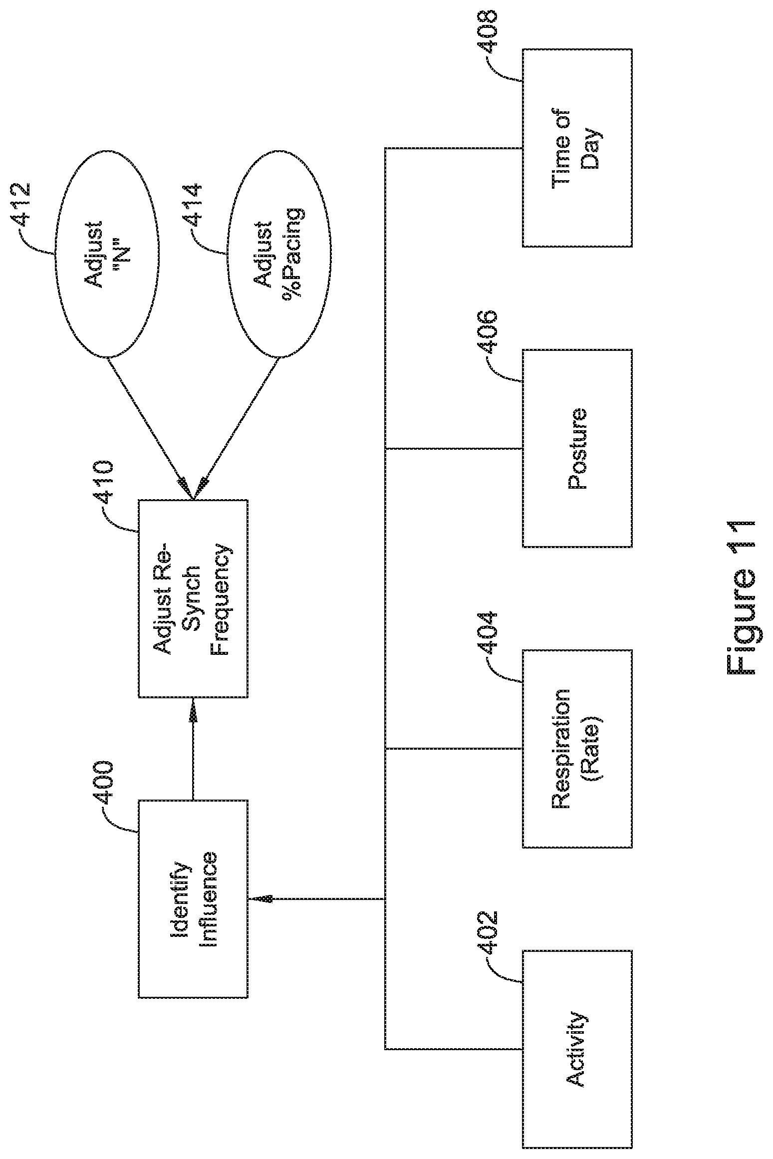
6. The LCP of claim 1, wherein the control circuitry is configured to monitor patient status and make adjustments to the CRT including: sensing for a patient condition that would influence the reduction factor; detecting a change in the patient condition; and adjusting the reduction factor.
7. The LCP of claim 1, further comprising a posture sensor, wherein the control circuitry is configured to monitor patient posture and make adjustments to the CRT including: sensing a posture of the patient; determining whether the patient has changed postures; and in response to finding that the patient has changed postures, adjusting the reduction factor.
8. The LCP of claim 1, wherein the control circuitry is configured to monitor patient status and make adjustments to the CRT including sensing for a predetermined patient condition that may influence PR interval, and in response to sensing the predetermined patient condition, adjusting "N".
9. The LCP of claim 1, further comprising a posture sensor, wherein the control circuitry is configured to monitor patient posture and make adjustments to the CRT including: sensing a posture of the patient; determining that the patient has changed postures between standing and one of sitting or laying down; and: if the patient has gone from standing to sitting or laying down, increasing "N"; or if the patient has gone from sitting or laying down to standing, reducing "N".
10. The LCP of claim 1, wherein the control circuitry is configured to iteratively provide the CRT in sets and to adjust N after delivery of a plurality of sets by: observing changes in native R-R intervals, to calculate an R-R drift; and calculating N using the calculated drift.
11. The LCP of claim 1, wherein the control circuitry is configured for at least first and second modes of CRT therapy wherein: the first mode comprises delivering sets of CRT therapy via the combination of sensing a native R-R interval, delivering a synchronization pace therapy, and delivering a plurality of additional pace therapies; the second mode comprises obtaining atrial event timing information from a second implantable or wearable medical device to control or optimize pace therapy timing.
Description
BACKGROUND
Cardiac resynchronization therapy (CRT) modifies the electrical activation and contractions of the heart's chambers to enhance pumping efficiency. Benefits may include increased exercise capacity and reduced hospitalization and mortality. More particularly, CRT devices operate by affecting the timing of contraction of one or more cardiac chambers relative to one or more other cardiac chambers. For example, contractions of one or more of the ventricle(s) may be timed relative to contraction of the atria, or contractions of the left and right ventricles may be timed relative to one another.
A "fusion" beat occurs when multiple activation signals affect the same cardiac tissue at the same time. For example, electrical fusion between pacing of one ventricle with spontaneous activation of another ventricle (for example, paced left ventricular (LV) activation and intrinsic right ventricular (RV) activation) produces a fusion beat. The generation of fusion beats is a goal of CRT in many circumstances.
Prior systems generally include intracardiac electrodes coupled via transvenous leads to an implanted pulse generator. The leads of such systems are widely known as introducing various morbidities and are prone to eventual conductor and/or insulator failure. Such issues likely reduce usage of CRT within the indicated population of heart failure patients.
Such prior lead systems typically include ventricular and atrial components to facilitate sensing of atrial and ventricular events to enhance CRT timing. For example, in some patients, CRT may be achieved by pacing the left ventricle at a specific time relative to detection of an atrial event. The sensed atrial signal may conduct to the right ventricle (RV) via natural conduction to generate an RV contraction, with paced LV contraction occurring at a desirable time relative to the RV contraction to yield a fusion beat. The interval from the atrial sensed event to the LV pace may be adjusted to enhance cardiac response in prior systems.
Newer generation pacemakers include the leadless cardiac pacemaker (LCP), which can be implanted entirely within the heart and does not require a transvenous (or any) lead. Such devices are commercially available on a limited basis, but are currently indicated for and capable of use in only bradycardia pacing. With further enhancements, the LCP also presents an opportunity to provide an alternative to traditional CRT using transvenous leads. New and alternative systems, devices and methods directed at providing CRT using the LCP are desired.
OVERVIEW
The present inventor has recognized, among other things, that a problem to be solved is that the absence of an intracardiac lead makes detection of an atrial event for purposes of CRT potentially difficult for a system using one or more ventricular LCP devices. Methods and devices to facilitate CRT from an LCP implanted in the left ventricle are disclosed. These methods may be used in a stand-alone LCP, or in a system comprising both an LCP and one or more additional devices such as another LCP, an implantable cardiac monitor, or an implantable defibrillator.
A first illustrative and non-limiting example takes the form of a method of delivering cardiac resynchronization therapy (CRT) from a leadless cardiac pacemaker (LCP) implanted in or proximate to the left ventricle of a patient, the method comprising: in an initialization phase: determining a PR interval for the patient's cardiac activity; and determining a reduction factor related to at least the PR interval; in a pacing phase, performing the following in iterations: measuring a native beat interval; delivering at least one synchronization pace at an interval that is reduced relative to the native beat interval by the reduction factor; and delivering a plurality, "N", of pacing therapies at a therapy interval; wherein the therapy interval is approximately equal to the native beat interval.
Additionally or alternatively, the LCP may be implanted such that the LCP lacks an atrial lead or electrodes to independently provide timing references from the atria for therapy delivery.
Additionally or alternatively, the step of determining the reduction factor may comprise using an external programmer to receive the reduction factor.
Additionally or alternatively, the step of determining the reduction factor may comprise multiplying the PR interval by a variable, % PR, to determine the reduction factor.
Additionally or alternatively, the variable % PR may be obtained using an external programmer or from a stored value in the LCP.
Additionally or alternatively, the reduction factor may be calculated as follows: in the initialization phase, a ratio of the RR interval between native ventricular events and a PR interval within one or more native ventricular events is calculated and stored as a first variable; a variable, % PR is obtained from memory or from a user/physician; and the reduction factor is calculated as one minus the product of the first variable and the % PR; and further wherein in the pacing phase, the synchronization pace is delivered at an interval calculated by multiplying the reduction factor and native beat interval.
Additionally or alternatively, the PR interval may be obtained in-clinic and entered via an external programmer. Additionally or alternatively, the PR interval is measured by a second implantable medical device monitoring one or more cardiac electrical signals and is then communicated to the LCP.
Additionally or alternatively, the first illustrative method may further comprise: sensing for a patient condition that would influence the reduction factor; detecting a change in the patient condition; and adjusting the reduction factor.
Additionally or alternatively, the first illustrative method may further comprise sensing a posture of the patient; determining that the patient has changed postures; determining that the reduction factor should be adjusted in light of the patient posture change; and adjusting the reduction factor.
Additionally or alternatively, the first illustrative method may further comprise sensing for a patient condition that may influence PR interval, finding that the patient condition has changed, and adjusting "N".
Additionally or alternatively, the first illustrative method may further comprise sensing a posture of the patient; determining that the patient has changed postures between standing and one of sitting or laying down; and: if the patient has gone from standing to sitting or laying down, increasing "N"; or if the patient has gone from sitting or laying down to standing, reducing "N".
A second illustrative and non-limiting example takes the form of a method of delivering cardiac resynchronization therapy (CRT) from a leadless cardiac pacemaker (LCP) implanted in or proximate to the left ventricle of the patient, the method comprising performing a method the first illustrative and non-limiting example (and/or any variant thereof just noted) and further: performing the initialization phase at least once; performing the pacing phase in at least first and second iterations using at least first and second measured native beat intervals; comparing the at least first and second measured native beat intervals and calculating a drift of the native beat interval in the at least first and second iterations; and determining N for use in a subsequent iteration of the pacing phase using the calculated drift.
A third illustrative and non-limiting example takes the form of a method of delivering cardiac resynchronization therapy (CRT) in an implantable medical device system comprising at least a leadless cardiac pacemaker (LCP) and a second implantable medical device, the method comprising: at a first time, delivering CRT in a first CRT method using the LCP to deliver pace therapy and using CRT timing information communicated by the second implantable medical device to control or optimize the CRT; encountering a difficulty with the first CRT method; and switching to performing the method as in the first illustrative and non-limiting example (and/or any variant thereof just noted) or second illustrative example.
A fourth illustrative and non-limiting example takes the form of a leadless cardiac pacemaker (LCP) configured for implantation entirely within a heart chamber of a patient or adjacent to a heart chamber of a patient, the LCP comprising: a plurality of electrodes for therapy delivery and cardiac electrical sensing; pacing circuitry to generate pacing therapy outputs; and control circuitry to control the use of the pacing circuitry using signals sensed from the electrodes; wherein the control circuitry is configured to provide cardiac resynchronization therapy (CRT) in sets using a predetermined reduction factor and a set parameter, "N", comprising delivering sets of CRT therapy including N pacing therapy outputs by: sensing a native R-R interval for the patient's heart; delivering a synchronization pace therapy at an interval, relative to a native ventricular event, calculated using the native R-R interval and the reduction factor; and delivering a plurality of additional pace therapies at intervals approximately equal to the native R-R interval.
Additionally or alternatively, the LCP may be implanted such that the LCP lacks an atrial lead or electrodes to independently provide timing references from the atria for therapy delivery.
Additionally or alternatively, the control circuitry may be configured to provide the CRT without using an atrial sense reference.
Additionally or alternatively, the control circuitry may be configured to perform an initialization of CRT to determine the reduction factor by: determining a PR interval for the patient's cardiac activity; and multiplying the PR interval by a variable, % PR, to calculate the reduction factor.
Additionally or alternatively, the control circuitry may be configured to obtain % PR either by communication with an external programmer or from a stored value in the LCP.
Additionally or alternatively, the control circuitry may be configured to perform an initialization of CRT to determine the reduction factor by: sensing one or more native ventricular events to calculate an RR interval between native ventricular events and a PR interval within one or more native ventricular events; calculating a RR:PR ratio as a ratio of the RR interval to the PR interval; obtaining a variable, % PR, from memory or from an external programmer; and calculating the reduction factor as one minus the product of the first variable and the % PR; and further wherein the control circuitry is configured to calculate the interval for the synchronization pace therapy by multiplying the reduction factor and the native beat interval.
Additionally or alternatively, the control circuitry may be configured to perform an initialization of CRT to determine the reduction factor by: sensing one or more native ventricular events to calculate an RR interval between native ventricular events; communicating with a second device to determine when P-waves occurred in the one or more native ventricular events and calculating a PR interval; calculating a RR:PR ratio as a ratio of the RR interval to the PR interval; obtaining a variable, % PR, from memory or from an external programmer; and calculating the reduction factor as one minus the product of the first variable and the % PR; and further wherein the control circuitry is configured to calculate the interval for the synchronization pace therapy by multiplying the reduction factor and the native beat interval.
Additionally or alternatively, the control circuitry may be configured to monitor patient status and make adjustments to the CRT including: sensing for a patient condition that would influence the reduction factor; detecting a change in the patient condition; and adjusting the reduction factor.
Additionally or alternatively, the LCP may further comprise a posture sensor, wherein the control circuitry may be configured to monitor patient status and make adjustments to the CRT including: sensing a posture of the patient; determining whether the patient has changed postures; and in response to finding that the patient has changed postures, adjusting the reduction factor.
Additionally or alternatively, the control circuitry may be configured to monitor patient status and make adjustments to the CRT including sensing for a predetermined patient condition that may influence PR interval, and in response to sensing the predetermined patient condition, adjusting "N".
Additionally or alternatively, the LCP may further comprise a posture sensor, wherein the control circuitry may be configured to monitor patient status and make adjustments to the CRT including: sensing a posture of the patient; determining that the patient has changed postures between standing and one of sitting or laying down; and: if the patient has gone from standing to sitting or laying down, increasing "N"; or if the patient has gone from sitting or laying down to standing, reducing "N".
Additionally or alternatively, the control circuitry may be configured to iteratively provide the CRT in sets of N pacing pulses and to adjust N after delivery of a plurality of sets of N pacing pulses by: observing changes in native R-R intervals measured prior to delivery of the synchronization pace therapy in the plurality of sets, to calculate an R-R drift; and calculating N using the calculated drift.
Additionally or alternatively, the control circuitry may be configured for at least first and second modes of CRT therapy wherein: the first mode comprises delivering sets of CRT therapy including N pacing therapy outputs via the combination of sensing a native R-R interval, delivering a synchronization pace therapy, and delivering a plurality of additional pace therapies; and the second mode comprises obtaining atrial even timing information from a second implantable or wearable medical device to control or optimize pace therapy timing.
A fifth illustrative and non-limiting example takes the form of an implantable medical device system comprising at least a leadless cardiac pacemaker (LCP) as in the fourth illustrative and non-limiting example (or any of the above variants thereof) and a second implantable medical device, the LCP and the second implantable medical device being configured for communicating with one another, wherein the system is configured to provide cardiac resynchronization therapy (CRT) in at least first and second approaches as follows: the first approach calls for the LCP to perform the first mode; and the second approach calls for the LCP and the second implantable medical device to cooperatively implement the second mode; wherein the system is configured to use the second approach by default and to use the first approach if difficulty is encountered with the second approach.
A sixth illustrative and non-limiting example takes the form of an implantable medical device system comprising at least a leadless cardiac pacemaker (LCP) as in the fourth illustrative and non-limiting example (or any of the above variants thereof) and a second implantable medical device, the LCP and the second implantable medical device being configured for communicating with one another, wherein the system is configured to provide cardiac resynchronization therapy (CRT) in at least first and second approaches as follows: the first approach calls for the LCP to perform the first mode; the second approach calls for the LCP and the second implantable medical device to cooperatively implement the second mode; and wherein the system is configured to use the first approach by default and to use the second approach if difficulty is encountered with the first approach.
An LCP as in any of the fourth, fifth and/or sixth illustrative and non-limiting examples, or any variant thereof, may use a state machine in the control circuitry and/or a microcontroller and memory storing executable instructions for the microcontroller.
This overview is intended to provide an introduction to the subject matter of the present patent application. It is not intended to provide an exclusive or exhaustive explanation of the invention. The detailed description is included to provide further information about the present patent application.
BRIEF DESCRIPTION OF THE DRAWINGS
In the drawings, which are not necessarily drawn to scale, like numerals may describe similar components in different views. Like numerals having different letter suffixes may represent different instances of similar components. The drawings illustrate generally, by way of example, but not by way of limitation, various embodiments discussed in the present document.
FIG. 1 illustrates a patient having an implantable leadless cardiac pacemaker (LCP) implanted in the left ventricle;
FIG. 2 shows an illustrative implantable leadless cardiac pacemaker;
FIG. 3 shows a patient having a plurality of implantable medical devices;
FIG. 4 shows an illustrative implantable medical device;
FIGS. 5-7 illustrate a method of LCP pacing for CRT;
FIG. 8A is a timing diagram illustrating a method as in FIG. 7;
FIG. 8B is a block diagram for overall management of a method of LCP pacing for CRT referencing the timing diagram of FIG. 8A;
FIGS. 9-13 illustrate sub-methods to adjust a method of LCP pacing for CRT;
FIG. 14 shows in block form transitions among a number of different CRT methods; and
FIG. 15 illustrates a method of handling ventricular beats should those occur during CRT as illustrated by other methods herein.
DETAILED DESCRIPTION
The following description should be read with reference to the drawings. The description and the drawings, which are not necessarily to scale, depict illustrative embodiments and are not intended to limit the scope of the disclosure.
FIG. 1 illustrates a patient 10 having an implanted leadless cardiac pacemaker 14 (LCP placed in the left ventricle of the patient's heart 12. The LCP 14 may be implanted in other chambers, such as the right ventricle, if desired, and as shown below, additional devices may also be implanted to act cooperatively with or independently of the LCP 14. Rather than implantation in the left ventricle, the LCP 14 may be implanted proximate to the left ventricle such as by implantation in a blood vessel of the heart that would place the LCP adjacent to the target chamber.
The LCP 14 is configured for communication with an external device 20 which may be, for example, a clinician programmer or, in some embodiments, may be some other device such as a mobile phone usable by the patient or a remote monitoring apparatus. The external device 20 may perform various processes and methods known in the art such as setting therapy or sensing parameters of the LCP and/or obtaining device diagnostics/settings as well as patient history or other information from the LCP 14.
Communication between the LCP 14 and external device 20 may use an optional wand 22 that can be placed on or near the patient to facilitate communication. For example the wand may be designed with two or more skin contact electrodes for conducted communication with an implantable device. Alternatively the wand may comprise a coil or antenna to facilitate inductive or radiofrequency communications, or may include an optical element(s) for infrared communication, or a transmitter and receiver for ultrasound communications, as desired. For example, Medradio communications in the 401-405 MHz band, Bluetooth or Bluetooth Low Energy, or Zigbee or other communications mode, may be facilitated by the provision of appropriate antennae and associated circuitry. The wand may be omitted and antenna and circuitry may be provided within or on the external device 20. Though not shown in detail, the external device 20 may include any suitable user interface, including a screen, buttons, keyboard, touchscreen, speakers, and various other features widely known in the art.
The LCP 14 may include at least two therapy delivery electrodes to act as anode and cathode for therapy delivery. The LCP 14 may be placed by advancing a catheter into the heart from, for example, a femoral location, and attaining access to the left ventricle and placing the LCP 14 adjacent to the myocardium and engaging attachment features, such as tines, hooks, or helical coils, for example, thereto. Delivery, tissue attachment and retrieval features may be included in the LCP including those features shown in US PG Patent Publications 20150051610, titled LEADLESS CARDIAC PACEMAKER AND RETRIEVAL DEVICE, and 20150025612, titled SYSTEM AND METHODS FOR CHRONIC FIXATION OF MEDICAL DEVICES, the disclosures of which are incorporated herein by reference. Delivery, fixation and retrieval structures may also resemble that of the Micra.TM. (Medtronic) or Nanostim.TM. (St. Jude Medical) leadless pacemakers.
The LV placement may be particularly useful for cardiac resynchronization therapy (CRT) purposes. In CRT, as explained in the Background, one goal is to time delivery of pacing to one or more ventricles to cause electrical "fusion" wherein the ventricular contraction is made stronger by activation of tissue due to convergence of multiple electrical signals. A therapy delivered to the LV can converge with the electrical wavefront moving inferiorly through the heart's natural conduction path to enhance cardiac output/efficiency.
While the LV is a good place from which to deliver therapy, an LCP may not be able to adequately sense atrial activity from the LV well enough to independently manage CRT pace timing in all patients and/or at all times. It is likely that in at least some circumstances, an LV-placed LCP will be able to do some atrial sensing using electoral or mechanical signals, however, further options are desired.
Methods described below are intended to provide additional options for an LV located LCP to provide CRT. Such methods may be embodied in devices having operational circuitry configured to perform the methods, such as by including dedicated circuitry for certain functions as well as stored instruction sets to be operated by a processor or controller, or by providing one or more state machines to perform identified functions in various configurations.
Some patients may also or instead need a right ventricle (RV) located LCP to facilitate CRT. The methods and devices herein may be further configured for use in the RV such as by adjusting timing interval calculations to accommodate a location in the RV.
FIG. 2 shows an illustrative LCP design. The LCP 50 is shown as including several functional blocks including a communications module 52, a pulse generator module 54, an electrical sensing module 56, and a mechanical sensing module 58. In some examples, the electrical sensing module 56 and mechanical sensing module 58 may be configured to sense one or more biological signals for use in one or more of determining timing for CRT, identifying physiological conditions, such as those affecting the parasympathetic nervous system that may affect CRT timing needs, and/or for assessing CRT efficacy, as further described below.
A processing module 60 may receive data from and generate commands for outputs by the other modules 52, 54, 56, 58. An energy storage module is highlighted at 62 and may take the form of a rechargeable or non-rechargeable battery, or a supercapacitor, or any other suitable element. Various details and/or examples of internal circuitry, which may include a microprocessor or a state-machine architecture, are further discussed in US PG Patent Publications 20150360036, titled SYSTEMS AND METHODS FOR RATE RESPONSIVE PACING WITH A LEADLESS CARDIAC PACEMAKER, 20150224320, titled MULTI-CHAMBER LEADLESS PACEMAKER SYSTEM WITH INTER-DEVICE COMMUNICATION, 20160089539, titled REFRACTORY AND BLANKING INTERVALS IN THE CONTEXT OF MULTI-SITE LEFT VENTRICULAR PACING, and 20160059025, titled, MEDICAL DEVICE WITH TRIGGERED BLANKING PERIOD, as well as other patent publications. Illustrative architectures may also resemble those found in the Micra.TM. (Medtronic) or Nanostim.TM. (St. Jude Medical) leadless pacemakers.
The device is shown with a first end electrode at 64 and a second end electrode at 66. A retrieval feature is shown schematically at 70 and may be, for example, a short post with an opening therethrough to receive a retrieval hook. A number of tines 68 may extend from the device in several directions. The tines 68 may be used to secure the device in place within a heart chamber. An attachment structure may instead take the form of a helical screw, if desired. In some examples, tines 68 are used as the only attachment features. As noted above, delivery, tissue attachment and retrieval features may be included in the LCP including those features shown in US PG Patent Publications 20150051610, and/or 20150025612, titled SYSTEM AND METHODS FOR CHRONIC FIXATION OF MEDICAL DEVICES, for example. Delivery, fixation and retrieval structures may also resemble that of the Micra.TM. (Medtronic) or Nanostim.TM. (St. Jude Medical) leadless pacemakers.
FIG. 3 illustrates a patient 100 with an LCP 104 implanted inside the heart 102, in the left ventricle for illustrative purposes. Optionally a second LCP 106 is shown in the right ventricle of the heart 102. If desired further devices may be provided by having, for example, an LCP in one of the atria.
The patient 100 also has implanted another medical device in the form of a subcutaneous implantable defibrillator (SICD) having a left axillary canister 110 and a lead 112. The illustrative lead 112 is shown with a defibrillation coil 114 and sensing electrodes 116, 118 distal and proximal of the coil 114. A still more proximal sense electrode may also be provided as shown at 120. For securing the lead subcutaneously, one or more suture sleeves may be provided and/or the distal tip electrode 116 may be secured to the fascia by the use of a suture or clip engaging a suture hole in the distal tip.
In some embodiments the lead may be as shown, for example, in U.S. Pat. No. 9,079,035, titled ELECTRODE SPACING IN A SUBCUTANEOUS IMPLANTABLE CARDIAC STIMULUS DEVICE, the disclosure of which is incorporated herein by reference. Plural leads may be provided as shown, for example, in U.S. Pat. No. 7,149,575, titled SUBCUTANEOUS CARDIAC STIMULATOR DEVICE HAVING AN ANTERIORLY POSITIONED ELECTRODE or, alternatively, the lead may have a bifurcation. Any suitable design for single, multiple, or bifurcated implantable leads may be used.
The lead 112 may be implanted entirely subcutaneously, such as by extending across the anterior or posterior of the chest, or by going partly across the chest in a lateral/medial direction and then superiorly toward the head along the sternum. Some examples and discussion of subcutaneous lead implantation may be found in U.S. Pat. No. 8,157,813, titled APPARATUS AND METHOD FOR SUBCUTANEOUS ELECTRODE INSERTION, and US PG Publication No. 20120029335, titled SUBCUTANEOUS LEADS AND METHODS OF IMPLANT AND EXPLANT, the disclosures of which are incorporated herein by reference. Additional subcutaneous placements are discussed in U.S. Pat. No. 6,721,597, titled SUBCUTANEOUS ONLY IMPLANTABLE CARDIOVERTER DEFIBRILLATOR AND OPTIONAL PACER, and the above mentioned U.S. Pat. No. 7,149,575, the disclosures of which are incorporated herein by reference.
A substernal placement may be used instead, with the distal end of the lead 112 (that is, the end distant from the canister 110) going beneath the sternum. Some examples of such placement are described in US PG Patent Pub. No. 20170021159, titled SUBSTERNAL PLACEMENT OF A PACING OR DEFIBRILLATING ELECTRODE, the disclosure of which is incorporated herein by reference. Still another alternative placement is shown in U.S. patent application Ser. No. 15/667,167, titled IMPLANTATION OF AN ACTIVE MEDICAL DEVICE USING THE INTERNAL THORACIC VASCULATURE, the disclosure of which is incorporated herein by reference.
The devices 104, 106 (optionally), 110 may communicate with one another and/or with an external programmer 130 using conducted communication, in some examples. Conducted communication is communication via electrical signals which propagate via patient tissue and are generated by more or less ordinary electrodes. By using the existing electrodes of the implantable devices, conducted communication does not rely on an antenna and an oscillator/resonant circuit having a tuned center frequency or frequencies common to both transmitter and receiver radiofrequency or inductive communication may be used instead. Alternatively the devices 104, 106 (optionally), 110 may communicate via inductive, optical, sonic, or radiofrequency communication, or any other suitable medium.
Subcutaneous implantable defibrillators may include, for example, the Emblem S-ICD System.TM. offered by Boston Scientific Corporation. Combinations of subcutaneous defibrillators and LCP devices are discussed, for example, in US PG Patent Publication Nos. 20160059025, 20160059024, 20160059022, 20160059007, 20160038742, 20150297902, 20150196769, 20150196758, 20150196757, and 20150196756, the disclosures of which are incorporated herein by reference. The subcutaneous defibrillator and LCP may, for example, exchange data related to cardiac function or device status, and may operate together as a system to ensure appropriate determination of cardiac condition (such as whether or not a ventricular tachyarrhythmia is occurring), as well as to coordinate therapy such as by having the LCP deliver antitachycardia pacing in an attempt to convert certain arrhythmias before the subcutaneous defibrillator delivers a defibrillation shock. In addition, the two systems may coordinate as set forth herein to provide cardiac resynchronization therapy (CRT).
In some examples, rather than a therapy device such as the SICD shown in FIG. 3, a second implantable medical device may take the form of an implantable monitoring device such as a subcutaneous cardiac monitor (SCM). An SCM may be, for example, a loop monitor that captures data under select conditions using two or more sensing electrodes on a housing thereof and/or attached thereto with a lead. Such monitors have found use to assist in diagnosing cardiac conditions that may be infrequent or intermittent, or which have non-specific symptoms. In the context of the present invention, an SCM, or even a wearable cardiac monitor, may be used in place of the SICD as described in any of the following examples.
Several examples focus on using a left ventricular LCP 104. However, some examples may instead use a right ventricular LCP 106, and other examples may include both the left ventricular LCP 104 and right ventricular LCP 106. In other examples, a three implant system may include two LCP devices 104, 106, as well as a subcutaneous device such as the SICD 110 as shown. In still other examples, an atrial-placed LCP (not shown) may also be included or may take the place of one of the ventricular LCP devices 104, 106 and/or the SICD 110.
FIG. 4 illustrates a block diagram of an implantable medical device. The illustration indicates various functional blocks within a device 150, including a processing block 152, memory 154, power supply 156, input/output circuitry 158, therapy circuitry 160, and communication circuitry 162. These functional blocks make up at least some of the operational circuitry of the device. The I/O circuitry 158 can be coupled to one or more electrodes 164, 166 on the housing of the device 150, and may also couple via a header 168 for attachment to one or more leads 170 having additional electrodes 172.
The processing block 152 will generally control operations in the device 150 and may include a microprocessor or microcontroller and/or other circuitry and logic suitable to its purpose. A state machine may be included. Processing block 152 may include dedicated circuits or logic for device functions such as converting analog signals to digital data, processing digital signals, detecting events in a biological signal, etc. The memory block may include RAM, ROM, flash and/or other memory circuits for storing device parameters, programming code, and data related to the use, status, and history of the device 150. The power supply 156 typically includes one to several batteries, which may or may not be rechargeable depending on the device 150. For rechargeable systems there would additionally be charging circuitry for the battery (not shown) including for example a coil for receiving energy and regulating and rectification circuitry to provide received energy to a rechargeable battery or supercapacitor.
The I/O circuitry 158 may include various switches or multiplexors for selecting inputs and outputs for use. I/O circuitry 158 may also include filtering circuitry and amplifiers for pre-processing input signals. In some applications the I/O circuitry will include an H-Bridge to facilitate high power outputs, though other circuit designs may also be used. Therapy block 160 may include capacitors and charging circuits, modulators, and frequency generators for providing electrical outputs. A monitoring device may omit the therapy block 160 and may have a simplified I/O circuitry used simply to capture electrical or other signals such as chemical or motion signals.
The communication circuitry 162 may be coupled to an antenna 174 for radio communication (such as Medradio, ISM, Bluetooth, or other radiofrequency protocol/band), or alternatively to a coil for inductive communication, and/or may couple via the I/O circuitry 158 to a combination of electrodes 164, 166, 172, for conducted communication. Communication circuitry 162 may include a frequency generator/oscillator and mixer for creating output signals to transmit via the antenna 174. Some devices 150 may include a separate or even off-the shelf ASIC for the communications circuitry 162, for example. For devices using an inductive communication output, an inductive coil may be included. Devices may use optical or acoustic communication, and suitable circuits, transducers, generators and receivers may be included for these modes of communication as well or instead of those discussed above.
As those skilled in the art will understand, additional circuits may be provided beyond those shown in FIG. 4. For example, some devices 150 may include a Reed switch, Hall Effect device, or other magnetically reactive element to facilitate magnet wakeup, reset, or therapy inhibition of the device by a user, or to enable an MRI protection mode. A device lacking a lead may have plural electrodes on the housing thereof, as indicated at 164, 166, but may omit the header 168 for coupling to lead 170.
A device as in FIG. 4 may be embodied as a subcutaneous implantable defibrillator as shown above in FIG. 3. Alternatively a device 150 may be embodied as an implantable defibrillator and/or pacemaker as in US PG Patent Pub. No. 20170021159, titled SUBSTERNAL PLACEMENT OF A PACING OR DEFIBRILLATING ELECTRODE, the disclosure of which is incorporated herein by reference. Still another alternative placement is shown in U.S. patent application Ser. No. 15/667,167, titled IMPLANTATION OF AN ACTIVE MEDICAL DEVICE USING THE INTERNAL THORACIC VASCULATURE, the disclosure of which is incorporated herein by reference. Still further, a device 150, omitting the therapy circuitry 160 if desired, may be embodied as an implantable cardiac monitoring system.
FIGS. 5-7 illustrate a method of LCP pacing for CRT. FIG. 5 shows the method at a high level as being an approach for stand-alone LV LCP pacing, as indicated at 200. A setup process, shown in FIG. 6, is performed as indicated at 210. Next, ambulatory operation 250 takes place, as further detailed below in FIG. 7. Upon occurrence of a reset 202 of the device, optionally, the system may return to the setup process 210. Upon occurrence of one or a plurality of errors, such as a persistent failure of one or more types, setup 210 may be revisited. For example, if desired, one or more measures of CRT success may be monitored such as review of cardiac contractility, occurrence of fusion pacing events, changes in patient fluid status, occurrence of desirable hemodynamic outcomes as indicated by strength of cardiac beats or changes in pressure in the heart or blood vessels, for example, and failure to attain desired outcomes may be viewed as an error 204 triggering return to setup. In the most likely to occur of these return states, a physician intervention may occur, such as when a patient goes to the clinic for a follow-up (or has, if enabled, a follow-up via remote telemetry) with a physician 206 who may oversee a re-visit to the setup 210.
Turning to FIG. 6, the setup process is shown at 210. A pre-excitation interval, PRX, is to be determined as indicated at 212. In a simplest approach, PRX can be directly determined 214 by having the physician enter the desired PRX 216 using a clinician programmer. The entered value for PRX can then be used in ambulatory operation 250 which is further discussed in FIG. 7. PRX is one type of "reduction factor (RF)" that may be used in some embodiments; another example of an RF is also described below.
A calculated approach 220 is also provided. Here, the PR interval is measured 224--that is, an interval from the P-wave to the R-wave for the patient is determined using, for example, measurement of such an interval in one or a plurality of cardiac cycles. Step 224 may be performed in-clinic 226 under the supervision of a physician or otherwise qualified personnel. Alternatively, step 224 may be performed by a second implant 228 such as an extracardiac device (ED), for example, a subcutaneous implantable cardioverter defibrillator (SICD) or subcutaneous cardiac monitor (SCM), or even another LCP. In a still further alternative, the LCP itself may measure a PR interval by, for example, obtaining a heart sound associated with occurrence of a P-wave and assuming an interval between occurrence of the heart sound and the desired atrial fiducial.
Next, a variable, % PR, is obtained for use in calculating PRX, as indicated at 230. The variable may be provided by a physician overseeing the procedure, or it may be pre-set, for example, as a desired target based on general population studies. For example, given a P-R interval, the point in time at which pacing for CRT should be delivered may be assumed to be some fraction of the P-R interval such as in the range of about 25% to about 60%, or about 35% to about 50% of the P-R interval prior to the oncoming R-wave. Thus, as an example, if the RR interval is 1000 ms, the % PR is 60%, and the PR interval is 160 ms, then a pace therapy for CRT may desirably precede the R-wave by 96 ms, or 60% of the PR interval. In the illustrative example, 40% of the PR interval would be subtracted from the RR interval to yield a synchronization pulse interval.
The pre-excitation interval, PRX can then be calculated as the product of the measured PR interval times the obtained or entered % PR, as shown at 232. With PRX calculated, the method then turns to ambulatory operation 250 shown in FIG. 7.
FIG. 7 illustrates steps for ambulatory operation. Following setup 210, a native interval between R-waves, QRS complexes, or "beats" is measured, as indicated at 252.
This interval may be obtained using any suitable method such as by monitoring the electrocardiogram as received at the LCP; other methods may be used such as by monitoring for heart sounds, motion, or pressure events inside the heart, if desired. The interval is "native" insofar as at least the latter cardiac cycle of the two surrounding the interval is not artificially paced. The measured interval is then an interval between two ventricular events, or VVInt. If desired, both of the preceding and following ventricular events defining the native interval may be non-paced.
A single, "Synchronization" occurs with a pace therapy delivered at an interval that is equal to VVInt less PRX, as indicated at 254. Then a plurality of beats are paced at intervals equal to VVInt. By pacing at an interval, as used herein, the intent is that a pace therapy output is delivered following expiration of the interval from a preceding sensed ventricular event or pace therapy delivery. Thus, the pace at 254 follows expiration of an interval following a native ventricular event, while the paces at 256 are each taking place following expiration of an interval following a previous pace therapy delivery.
After "N" beats are paced, the method returns from block 256 to block 252 to obtain a new VVInt. The loop back to measure VVInt acknowledges, in part, that the patient's native heart rate may change over time as, for example and without limitation, the patient moves, undertakes an activity, becomes excited, falls asleep, or is affected by an ingested chemical such as caffeine. In the figure, the combination of blocks 252, 254 serve as synchronization cycles comprising a native cardiac cycle and a paced cardiac cycle. The pace therapy at 254 also serves as a CRT delivery cycle along with those delivered in block 256.
During therapy cycling, the device monitors the cardiac electrical signal to ensure that a new ventricular beat does not occur between pace therapy outputs. Such beats may take place if, for example, an ectopic beat, such as premature ventricular contraction, occurs, or if an atrial arrhythmia such as atrial fibrillation, conducts to the ventricle(s). If this occurs it may be treated as an error as indicated at 280, and may be handled as shown below in FIG. 15, returning to one of block 252 or block 254, as desired. In addition, one or more physiological signals of the patient may be monitored as illustrated below in FIGS. 9-13, yielding an adjustment to one or more parameters as indicated at 290. For example, PRX (or other reduction factor, RF) or "N" may be modified in light of a sensed condition as shown in FIGS. 9-13.
In operation, the method as shown in FIG. 7 will provide a percent therapy delivery for CRT pacing of (N+1)/(N+2). The percent therapy delivery can be manipulated by increasing or decreasing N, and may be further reduced if desired by introducing delays between sets. Studies have shown, however that a higher percent therapy delivery tends to result in greater therapy benefit. On the other hand, as shown in FIG. 8A, the underlying rhythm may drift over time to yield changes in the PR interval and/or RR interval that can reduce efficacy during performance of step 256. These tradeoffs can be handled to some extend by using methods shown in FIGS. 9-13 below to increase or decrease the percent therapy delivery in response to select conditions. In general, a range of N may be anywhere from 5 up to about 50, or higher or lower, if desired. In an example, N may be incremented up and down in steps of 1, 2, 5 or 10, or other increment.
FIG. 8A is a timing diagram illustrating a method as in FIG. 7. Atrial events (P-waves) are shown on the line at 300; each dark vertical line along the horizontal axis at 300 represents a P-wave or atrial depolarization. Axis 310 shows ventricular depolarizations in the dark vertical lines on the horizontal axis. Paced ventricular events on axis 310 are marked as Vp, and native events marked as Vs. Certain intervals are marked for the first two cardiac cycles on the left hand side, including the PR interval at 302 from an atrial event to the subsequent ventricular event, an RP interval at 312 from a ventricular event to the subsequent atrial event, and the RR interval between two consecutive ventricular events at 314. Going to the right hand side of the figure, the PR intervals continue to be called out.
The lower portion of FIG. 8A shows pace intervals with characterizations and durations. At 320 is a measurement beat. The measurement beat is what would be observed at block 252 of FIG. 7, as the ventricular event Vs that ends the interval is a native beat and is not paced. Next a synchronization beat is delivered, as indicated at 322, which would match therapy delivery at block 254 of FIG. 7. Then a set of "N" therapy beats are delivered at 324, corresponding to the delivery of CRT therapy in block 256 of FIG. 7. The process then iterates with a measurement beat at 330, a synch beat at 332, and another set of therapy beats at 334.
Illustrative intervals are shown in blocks 320, 322 and associated with 324. In this example, the measured beat interval has a duration of 900 milliseconds, which would correspond to about 67 beats per minute. The synchronization beat in this example is delivered at a shorter interval, in this case, 828 milliseconds following the native ventricular event Vs that ends the measurement beat interval. For this illustrative, non-limiting example, the value for PRX is 72 milliseconds, which could be calculated, for example, using 45% of a 160 millisecond PR interval. The numerical solution is hypothetical but likely in the range of what a real world patient would experience. Another illustrative approach may take into account the relative length of the PR interval to the RR interval as follows. In an example, the setup phase may determine the RR interval and PR interval at a given point in time and generate a PR:RR ratio. For example, if the RR interval is measured at 800 milliseconds and the PR interval is 160 milliseconds, then the PR:RR interval would be 160/800=0.2, which can be referred to as the "Ratio". Then a Pre-Excitation Percentage (PEP) may be provided by the physician or pre-set by the device, for example in the range of 30% to 50%; in one example, the PEP is set to 40%. In the ambulatory setting, the synchronization pace interval can be set as follows: Synch_Interval=VVInt*(1-Ratio*PEP) Assuming VVInt is measured at 900 millisecond, then the outcome given a Ratio of 0.2 and a PEP of 40% is: Synch_Interval=900 ms*(1-0.2*0.4)=900*(0.92)=828 ms In operation, for the Ambulatory Setting, block 328 may be revised to state that a pace therapy is delivered at VVInt*Synch_Fraction, where Sync Fraction is the product of the ratio of the measured PR to RR intervals, and the PEP. In the remaining explanation and Figures, PRX and/or the combination calculated factor (1-Ratio*PEP) may be treated as reduction factors (RF) that are used to reduce VVInt for purposes of delivering the Synch Interval.
One of the reasons for limiting "N" is illustrated at 326, where the P to Vp interval drifts as the set of pace therapies are delivered. Drift would again occur within the therapy set at 334; at least for the initial few beats the drift is likely to be small but it may grow over time as device settings and assumptions become less connected to the patient's changing physiological experience.
Such drift is not harmful within reasonable limits. For example, typically, a tolerance for drift may be in the range of 20 milliseconds or so in either direction and so random variation is likely tolerable. However, drift of the P-Vp interval may not be purely random, for example, physiological conditions of the patient can cause drift to occur in a directional manner. For example, if the patient begins exercising or changes posture causing a change in sympathetic tone, the actual underlying PR interval may change, or the patient's heart rate may change causing changes in the RR interval which, in turn would make the pace therapy delivery mis-timed relative to the P-wave as metabolic demand may change the time of P-wave appearing on the atrial axis 300 (which is not paced), but the pacing on the ventricular axis 310 remains fixed. In some examples, also laid out below, the actual PR interval even at the same RR interval may be different depending on certain factors such as posture, and accommodations for that may also be made.
In some examples, N may be selected for a given patient in view of a physician's experience with the patient and/or in light of information gathered for a patient. For example, a patient may receive a wearable monitoring system or implantable monitor to determine PR variability in order to determine how N may be set, in advance of LCP implantation by seeing how quickly the patient's heart rate or other characteristics change in response to activity, posture change, sleep, excitement, etc. In another example, wearable or additional implantable device may be provided after implantation of the LCP to monitor pacing effectiveness for a time period to determine a range for N, as well as other suitable patient diagnostics.
FIG. 8B illustrates an example wherein the LCP adjusts N based on the RR interval drift measured by the LCP in prior therapy sets. At 340 the LCP measures the RR interval, for example during the measurement beat 320 (FIG. 8A). At 342 the LCP delivers a set of N beats of CRT as illustrated in FIG. 8A. If at 344, M (e.g. 10) CRT sets have been delivered, a new N is calculated at 346.
In most patients there is a strong relationship between the RR and PR intervals. Thus measuring the RR interval drift (RR.sub.Drift) can be used to estimate the drift in the PR interval. For example, the PR drift may be about one fifth the RR drift. As noted above, in some examples, the usable value of N is dependent on the PR drift and the tolerance of CRT to deviations from the desired AV delay (AVD.sub.Tol). In an example, the new N can be calculated as follows: N.sub.New=N.sub.Old*(5*|AVD.sub.Tol/RR.sub.Drift|)
For example, if over the last 10 CRT sets the RR interval drift is +120 ms, the AV delay tolerance is 30 ms and the present N is 25, the new N would be 25*(5*|30 ms/120 ms|)=31(N.sub.New being rounded to the nearest integer). In another example, if over the last 10 CRT sets the RR interval drift is -150 ms, the AV delay tolerance is 25 ms and the present N is 30, the new N would be 30*(5*125 ms/-150 ms|)=25. In some examples the ratio of the PR interval to RR interval is fixed (e.g. 5). In some examples the PR interval varies by patient or time and can be attained via physician entry or measurement via another device.
In still other examples, below, N maybe modified in light of additional patient conditions.
FIGS. 9-13 illustrate sub-methods to adjust a method of LCP pacing for CRT. FIG. 9 shows an example in which an adjustment may be made between sets of CRT. In this example, the device (the LCP itself, or a second device communicatively linked to an LCP) identifies a physiological change that likely has an autonomic influence at 350, particularly with focus on any change that may affect the reduction factor (RF). If such a change is observed, a substitute reduction factor is inserted, RF', as indicated at 352. For example, referring to FIG. 7, this type of adjustment may be made at block 290, between therapy sets, as the modification of RF would be of most importance when RF is actually used during the synchronization pace step, and would have less importance, if any, during the actual set of therapies. However, in another example, if desired, the postural change may be used to interrupt the set of CRT pace therapies prior to reaching "N" therapies to force re-synchronization. Such an interruption may be treated as an error 280 forcing a return to the sense or synchronization steps of FIG. 7.
FIG. 10 shows a more specific example of the concept of FIG. 9. Here, RF may be calculated with the patient in a known posture, Posture 1, as indicated at 360. Then, the CRT therapy is delivered using RF as calculated for Posture 1 when the patient is in Posture 1 and, if the patient changes posture, as indicated at 362, a different RF value is selected 364.
For example, the setup process may comprise calculating a separate RF value for a plurality of posture by, for example, requesting the patient to assume and hold different postures while the RF calculation process(es) described above are repeated for each posture. Then, with the patient ambulatory, one of the RF values is selected at any given time based on the sensed posture of the patient. For example, posture may be sensed using an accelerometer. If the patient assumes a posture for which a RF value has not been identified, the RF value used may be an average or median of the RF values for various postures, or a value of RF in the last posture sensed for which RF has been calculated, for example.
FIG. 11 shows another example. Here, the value for "N" is adjusted in response to sensed conditions that may influence PR drift as highlighted above in FIG. 8A. First, a relevant influence is identified as indicated at 400. Some illustrative influences may be activity of the patient 402 (particularly where the activity level of the patient changes), respiration 404 (particularly interested again in changes in the rate or depth of respiration, for example), posture 406 (for example a patient in repose is less likely to have a significant change of heart rate and therefore may be better suited to larger "N" than one who is standing and more likely to have a change in heart rate), and/or time of day 408 (nighttime, while the patient is sleeping, may work better for a larger "N" than daytime, while the patient is awake). If an influence 400 changes, then the resynchronization frequency is adjusted 410 by, for example, modifying "N" as indicated at 412 which will, in turn, adjust the percent pacing and percent therapy delivery 414. The method of FIG. 11 may be included as part of the adjustment step at 290 in FIG. 7. Some influences, such as a change in activity 402, respiration 404, or posture 406, may also be used to trigger an interrupt or error 280 in FIG. 7, truncating a CRT therapy set, if desired.
FIGS. 12 and 13 show particular examples of the concept of FIG. 11. In FIG. 12, the patient's activity level is measured at 430 using, for example, an accelerometer to detect patient movement or, alternatively, a temperature sensor on the LCP that can detect a change in blood temperature in the heart, which will also suggest a change in metabolic demand and patient activity. "N" is then calculated (or recalculated) in response to the measured activity level, as indicated at 432.
FIG. 13 shows another example using posture this time. Posture sensing is performed at 450 to yield one of three outcomes (in this example--most posture definitions may be used if desired in other examples). The three outcomes include Posture 1, supine, as indicated at 452, in which re-synchronization may be performed relatively less frequently as indicated at 454. The three outcomes also include Posture 2, standing, as indicated at 460, in which case the system uses a smaller N and resynchronizes more frequently, as indicated at 462, than if the patient was supine. For this example, any other posture may be handled at block 456, "Other Posture", in which case reference may be made to another sensor as indicated at 458 such as an activity sensor, which can then be used to determine whether to use a larger N and re-synch less often 454, or a smaller N and re-synch more often 462. For example, if the patient is active at block 458, then re-synchronization may be performed more often as the patient's heart rate is more likely to change quickly while active. In an alternative, the other posture block 456 may simply go to one or the other of blocks 454, 462 automatically.
In still another alternative, N may be set according to the measured cardiac rate to ensure a frequency per unit time of re-synchronization. For example, a patient with a heart rate of 60 beats per minute would take 22 seconds, approximately, to proceed through one full therapy regimen as shown in FIG. 7 (1 native interval at 1 second, 20 paced intervals at 1 second, and 1 paced interval at 1 second less a reduction due to RF). If the heart rate is 100 beats per minute, a full therapy regimen as shown in FIG. 7 would take about 13 seconds instead. Normalizing N by rate might mean, for example, setting N to ensure it is revisited every 20 seconds, making N=18 when the heart rate is 60 beats per minute, and N=31 when the heart rate is 100 beats per minute. Other approaches may be used instead to modify N in light of patient conditions.
FIG. 14 shows in block form transitions among a number of different CRT methods. While some examples are directed at using an LCP implanted in the LV to provide stand-alone CRT, such as a system shown in FIG. 1, above, other examples may be part of a broader method and system to provide a number of CRT solutions in one system. For example, an LCP may be implanted with one or more additional devices such as another LCP, a subcutaneous implantable monitor, or a subcutaneous implantable defibrillator, as shown in FIG. 3, above. In still further alternatives, a wearable apparatus, or a completely different apparatus, such as an implantable neuromodulation device, drug pump, or other apparatus, may be useful to provide data that can be helpful in providing CRT.
FIG. 14 illustrates mode switching among a plurality of pacing modes for CRT, with modes indicated at 500, 510, 520, and 530. Modes 500, 510, and 520 are each cooperative modes in which a left ventricular placed LCP delivers pace therapy and receives timing assistance from a second device such as an extracardiac device (SICD and/or SCM, for example) or a second LCP placed else wherein the heart, while mode 530 represents an independent mode of operation for the LCP, where the LCP itself determines pace timing for CRT.
For example, mode 500 is an atrial-triggered mode, which may use cardiac electrical information such as the P-wave, as indicated at 502. Alternatively, mechanical or other sensor information may be captured and used as a trigger, as indicated at 504, such as by identifying a heart sound, motion in the atrium, or pressure changes in the atrium or related to atrial activity.
Predictive mode 510 may operate by controlling a pace-to-pace interval and reviewing past result of pace therapy delivery to adjust the pace-to-pace interval based on a "prediction" of when will be the right time to deliver a next pace therapy. For example, a predictive mode may use analysis of prior P-wave to pace intervals, as indicated at 512, or may use a morphology assessment of a QRS complex to determine whether the QRS complex has a shape that indicates fusion 514, using for examples rules or templates in the analysis. In still further examples of predictive pacing 510, a mechanical signal, such as the timing of heart sounds in relative sequence, may be analyzed as indicated at 516 to optimize pace timing.
Other signals may be assessed as well, as indicated at 520, including a septal signal such as the Q-wave onset, as indicated at 522. Non-electrogram signals may be used, such as a heart sound emanating from other than the atria at 524.
An autonomous mode for CRT pacing by an LCP may be used as well, as indicated at 530. Such an LCP may be placed in the left ventricle, and may be capable of various analysis to help with triggered or predictive pacing management. For example, the LCP may monitor for an atrial trigger 532 such as a heart sound or an electrical signal such as the P-wave. The LCP may instead use an impedance measurement, triggering pacing when the volume reaches a threshold level or change. The LCP may detect motion such as movement in the atria and trigger therapy. The LCP may have a sensor for sensing heart sounds and may detect a sound associated with atrial or right ventricular contraction, to trigger therapy delivery. A pressure signal may monitored to detect changes indicating atrial or right ventricular contraction triggering therapy output. An electrical input may be used by filtering to obtain a far-field signal from the atrium, or the LCP may have a short lead accessing the atria and can sense atrial signals. Any of these inputs may instead be used in a predictive method that analyzes past results and modifies pace to pace timing to achieve desirable CRT in subsequent pace therapy delivery. Another option is to use the reduction factor (RF) based approach shown above in FIGS. 5-7, as indicated at 534.
As indicated by the various arrows, the example may switch from one mode to another. Such switching may be based on errors or preference (E/P) as indicated at any of 540, 542, 544, 546. Errors may indicate that a particular mode or mode type is unreliable at a given time, while preference may indicate the order in which modes are to be made available.
For example, an atrial triggered mode 500 may be in use, however, upon loss of the atrial signal (caused by posture change, arrhythmia, or unknown cause) may trigger switching to use of an "other" signal in block 520, or to use of a predictive mode as indicated at 510. In several examples, a preference for cooperative modes may be in place, with switching to mode 530 performed only after other modes 500, 510, 520 are shown unreliable or ineffective. In other examples, any of modes 500, 510, 520, 530 may be used at any time simply based on which is deemed to be most reliable and/or to provide the preferred quality of CRT.
An atrial triggered mode may include, for example, sensing an atrial contraction using an electrical or mechanical signal. See, for example, U.S. patent application Ser. No. 15/633,517, titled CARDIAC THERAPY SYSTEM USING SUBCUTANEOUSLY SENSED P-WAVES FOR RESYNCHRONIZATION PACING MANAGEMENT, and/or U.S. patent application Ser. No. 15/642,121, titled METHOD AND SYSTEM FOR DETERMINING AN ATRIAL CONTRACTION TIMING FIDUCIAL IN A LEADLESS CARDIAC PACEMAKER SYSTEM, the disclosures of which are incorporated herein by reference
A predictive mode 510 may include, for example, monitoring evoked response(s) for fusion or comparing pace to R-wave (or other fiducial reference) timing to a target. See, for example, U.S. patent application Ser. No. 15/684,366, titled INTEGRATED MULTI-DEVICE CARDIAC RESYNCHRONIZATION THERAPY USING P-WAVE TO PACE TIMING, and/or U.S. patent application Ser. No. 15/684,264, titled CARDIAC RESYNCHRONIZATION USING FUSION PROMOTION FOR TIMING MANAGEMENT, the disclosures of which are incorporated herein by reference.
In addition, within the mode types, there may be multiple specific mode implementations such that a method or device can switch between modes of the same type. The assessment of different pacing modes, and switching between modes, may encompass the activation or deactivation of sensors and sensing capabilities specific to different modes. For example, an SICD or SCM may have multiple sensing channels and/or sense vectors that better target (using filtering or spatial differences) ventricular or atrial electrical signals. When a pacing mode relying on an electrical atrial signal is selected, the sense channel and/or sense vector best for atrial sensing may be activated; when a different pacing mode is selected, that same channel or vector may be deactivated to save power. A mechanical or optical sensor used in certain pacing modes may be deactivated when the relevant mode is not selected or under assessment.
Additional concepts related to switching between mode types for CRT using multiple cooperating devices may be found in U.S. patent application Ser. No. 15/710,118, titled MULTI-DEVICE CARDIAC RESYNCHRONIZATION THERAPY WITH MODE SWITCHING TIMING REFERENCE, the disclosure of which is incorporated herein by reference.
FIG. 15 illustrates a method of handling ventricular beats should those occur during CRT as illustrated by other methods herein. The illustration presumes action during the step of pacing "N" eats at VVInt as indicated at 600. Within block 600 there are at least three substeps going on. A pace output occurs at 602 in which therapy is delivered. Sensing may be blanked or refractory during pace output, if desired, and then comes on in an interval between pace outputs, as indicated at 604. When VVInt expires, at 606, the pacing method iterates until N is reached (N being reached is not explicitly shown), as indicated by the line back to 602.
If during the sensing step 604 a beat is detected, the loop is exited at 610 upon beat detection. If a single beat is detected, the method may wait one additional cycle 612 and then performs synchronization again, as indicated at 614. The waiting of one additional cycle 612 is optional; the device may instead simply jump directly to re-synchronizing at 614. For example, in an embodiment that waits 1 cycle 612, a new VVInt may be measured for use in the re-started CRT regimen. Alternatively, the previously measured VVInt may be preserved and the system may jump directly to re-synchronizing by delivering the synchronizing pace (pace at an interval of the preserved VVInt as reduced by RF). The beat detection at 610 may further trigger assessment of any possible influences, such as shown in FIGS. 11-13 to see if the "N" value should be changed in light of the patient being in a likely variable rate state, or if a different RF value might be called for using a method as shown in FIGS. 9-10, prior to returning to the resynchronization pulse.
A series of illustrative and non-limiting examples follows. These examples are provided for further illumination and is should be understood that other embodiments using other combinations of features are also contemplated.
An illustrative and non-limiting example takes the form of a leadless cardiac pacemaker (LCP) configured for implantation entirely within a heart chamber of a patient or adjacent to a heart chamber of a patient (item 14 in FIG. 1, for example), the LCP comprising: a plurality of electrodes for therapy delivery and cardiac electrical sensing (items 64, 66, 68 in FIG. 2, for example); pacing means to generate pacing therapy outputs (pulse generator module 54 in FIG. 2, for example); and control means to control the use of the pacing means using signals sensed from the electrodes (processing module 60 in FIG. 2); wherein the control means is configured to provide cardiac resynchronization therapy (CRT) in sets using a predetermined reduction factor and a set parameter, "N", comprising delivering sets of CRT therapy including N pacing therapy outputs by: sensing a native R-R interval for the patient's heart (operational circuitry, dedicated circuitry, a defined state of a state machine, and/or stored instruction set for performing as shown at block 252 in FIG. 7); delivering a synchronization pace therapy at an interval, relative to a native ventricular event, calculated using the native R-R interval and the reduction factor (operational circuitry, dedicated circuitry, a defined state of a state machine, and/or stored instruction set for performing as shown at block 254 in FIG. 7, with PRX determined as indicated by either block 216 or blocks 224, 230 and 232 of FIG. 6); and delivering a plurality of additional pace therapies at intervals approximately equal to the native R-R interval (operational circuitry, dedicated circuitry, a defined state of a state machine, and/or stored instruction set for performing as shown at block 256 in FIG. 7, for example).
Additionally or alternative, the control means may be configured to provide the CRT without using an atrial sense reference, as described repeatedly above and using the methods illustrated in FIGS. 6-7.
Additionally or alternatively, the control means may comprises initialization means configured to determine the reduction factor by: determining a PR interval for the patient's cardiac activity; and multiplying the PR interval by a variable, % PR, to calculate the reduction factor (such initialization means may include operational circuitry, dedicated circuitry, a defined state of a state machine, and/or stored instruction set for performing as shown in the calculated path 220, 224, 230, 232 in FIG. 6).
Additionally or alternatively, the control means may be configured to obtain % PR either by communication with an external programmer or from a stored value in the LCP (as indicated in the description of block 230 in FIG. 6, for example).
Additionally or alternatively, the control means comprises initialization means configured to determine the reduction factor by: sensing one or more native ventricular events to calculate an RR interval between native ventricular events and a PR interval within one or more native ventricular events; calculating a RR:PR ratio as a ratio of the RR interval to the PR interval; obtaining a variable, % PR, from memory or from an external programmer; and calculating the reduction factor as one minus the product of the first variable and the % PR; and further wherein the control means is configured to calculate the interval for the synchronization pace therapy by multiplying the reduction factor and the native beat interval. An example of this sort is explained above relative to FIG. 8A.
Additionally or alternatively, the control means may comprise initialization means configured to determine the reduction factor by: sensing one or more native ventricular events to calculate an RR interval between native ventricular events; communicating with a second device to determine when P-waves occurred in the one or more native ventricular events and calculating a PR interval; calculating a RR:PR ratio as a ratio of the RR interval to the PR interval; obtaining a variable, % PR, from memory or from an external programmer; and calculating the reduction factor as one minus the product of the first variable and the % PR; and further wherein the control means is configured to calculate the interval for the synchronization pace therapy by multiplying the reduction factor and the native beat interval. An example of this sort is explained above relative to FIG. 8A.
Additionally or alternatively, the LCP may further comprise a patient status monitoring means, and the control means is configured to make adjustments to the CRT including: using the patient status monitoring means to monitor a patient condition that would influence the reduction factor; detecting a change in the patient condition; and adjusting the reduction factor. For example, FIG. 9 shows an example where the control means identifies an autonomic influence, and replaces the reduction factor with a different value.
Additionally or alternatively, the LCP may be configured such that the status monitoring means comprises a posture sensor and the patient condition is a posture of the patient, such that the control means is configured to adjust the reduction factor in response to finding that the patient has changed postures. For example, FIG. 10 shows an example in which the control means identifies a reduction factor for a first posture, detects a change in posture, and replaces the reduction factor with a different value.
Additionally or alternatively, the LCP may comprise a patient status monitoring means, and the control means is configured to make adjustments to the CRT including: sensing for a predetermined patient condition that may influence PR interval; and in response to sensing the predetermined patient condition, adjusting "N". An example is shown in FIG. 11, in which a plurality of patient status means are identified including activity sensor 402, or respiration sensor 404, or posture sensor 406, or time of day determiner 408, any of which can be used by the control means (embodied as dedicated circuitry, a state machine, or controller acting on stored instructions, or a combination thereof) to operate as illustrated at block 400 and 410.
Additionally or alternatively, the LCP may comprise a posture sensor, wherein the control means is configured to monitor patient status and make adjustments to the CRT including: using the posture sensor to monitor a posture of the patient; determining that the patient has changed postures between standing and one of sitting or laying down; and: if the patient has gone from standing to sitting or laying down, increasing "N"; or if the patient has gone from sitting or laying down to standing, reducing "N". For example, FIG. 11 shows a posture sensor 406 as one of the means that a control means may rely upon to adjust the resynchronization frequency, with a specific example further detailed by FIG. 13 with reference to laying down 452 (such as supine posture) and standing up 460.
Additionally or alternatively, the LCP control means may be configured to iteratively provide the CRT in sets of N pacing pulses and to adjust N after delivery of a plurality of sets of N pacing pulses by: observing changes in native R-R intervals measured prior to delivery of the synchronization pace therapy in the plurality of sets, to calculate an R-R drift; and adjusting N using the calculated drift. An example of such a control means is described above relative to block 346 of FIG. 8B.
Additionally or alternatively, the LCP may further comprise communication means (FIG. 2, block 52) for communicating with a second medical device; wherein the control means is configured for at least first and second modes of CRT therapy wherein: the first mode comprises delivering sets of CRT therapy including N pacing therapy outputs via the combination of sensing a native R-R interval, delivering a synchronization pace therapy, and delivering a plurality of additional pace therapies, as recited in any of the preceding illustrative examples; and the second mode comprises using the communication means to obtain atrial event timing information from a second implantable or wearable medical device to control or optimize pace therapy timing. FIG. 14 illustrates multiple modes available for stand-alone LCP operation (530) and cooperative operation (510, 520, 530), including a specific reduction factor based method indicated at 534 which may take the form as shown in FIGS. 6-7, above.
Additionally or alternatively, an implantable medical device system comprising at least a leadless cardiac pacemaker (LCP) as in these illustrative examples, and a second implantable medical device, the LCP and the second implantable medical device configured for communicating with one another, wherein the system is configured to provide cardiac resynchronization therapy (CRT) in at least first and second approaches as follows: the first approach calls for the LCP to perform the first mode; and the second approach calls for the LCP and the second implantable medical device to cooperatively implement the second mode. FIG. 3 shows an example wherein a patient has multiple implanted devices configured to operate cooperatively in one or more modes, and FIG. 14 illustrates multiple modes available for stand-alone LCP operation (530) and cooperative operation (510, 520, 530), including a specific reduction factor based method indicated at 534 which may take the form as shown in FIGS. 6-7, above.
Additionally or alternatively, an LCP or a system as in any of these illustrative examples may be configured such that the control means comprises a state machine.
Additionally or alternatively, an LCP or a system as in any of these illustrative examples may be configured such that the control means comprises a microcontroller and memory storing executable instructions for the microcontroller.
Each of these non-limiting examples can stand on its own, or can be combined in various permutations or combinations with one or more of the other examples.
The above detailed description includes references to the accompanying drawings, which form a part of the detailed description. The drawings show, by way of illustration, specific embodiments in which the invention can be practiced. These embodiments are also referred to herein as "examples." Such examples can include elements in addition to those shown or described. However, the present inventor also contemplates examples in which only those elements shown or described are provided. Moreover, the present inventor contemplates examples using any combination or permutation of those elements shown or described (or one or more aspects thereof), either with respect to a particular example (or one or more aspects thereof), or with respect to other examples (or one or more aspects thereof) shown or described herein.
In the event of inconsistent usages between this document and any documents so incorporated by reference, the usage in this document controls. In this document, the terms "a" or "an" are used, as is common in patent documents, to include one or more than one, independent of any other instances or usages of "at least one" or "one or more." Moreover, in the following claims, the terms "first," "second," and "third," etc. are used merely as labels, and are not intended to impose numerical requirements on their objects.
Method examples described herein can be machine or computer-implemented at least in part. Some examples can include a computer-readable medium or machine-readable medium encoded with instructions operable to configure an electronic device to perform methods as described in the above examples. An implementation of such methods can include code, such as microcode, assembly language code, a higher-level language code, or the like. Such code can include computer readable instructions for performing various methods. The code may form portions of computer program products. Further, in an example, the code can be tangibly stored on one or more volatile, non-transitory, or non-volatile tangible computer-readable media, such as during execution or at other times. Examples of these tangible computer-readable media can include, but are not limited to, hard disks, removable magnetic or optical disks, magnetic cassettes, memory cards or sticks, random access memories (RAMs), read only memories (ROMs), and the like.
The above description is intended to be illustrative, and not restrictive. For example, the above-described examples (or one or more aspects thereof) may be used in combination with each other. Other embodiments can be used, such as by one of ordinary skill in the art upon reviewing the above description.
The Abstract is provided to comply with 37 C.F.R. .sctn. 1.72(b), to allow the reader to quickly ascertain the nature of the technical disclosure. It is submitted with the understanding that it will not be used to interpret or limit the scope or meaning of the claims.
Also, in the above Detailed Description, various features may be grouped together to streamline the disclosure. This should not be interpreted as intending that an unclaimed disclosed feature is essential to any claim. Rather, inventive subject matter may lie in less than all features of a particular disclosed embodiment. Thus, the following claims are hereby incorporated into the Detailed Description as examples or embodiments, with each claim standing on its own as a separate embodiment, and it is contemplated that such embodiments can be combined with each other in various combinations or permutations. The scope of the invention should be determined with reference to the appended claims, along with the full scope of equivalents to which such claims are entitled.
* * * * *
D00000
D00001
D00002
D00003
D00004
D00005
D00006
D00007
D00008
D00009
D00010
D00011
D00012

D00013

D00014
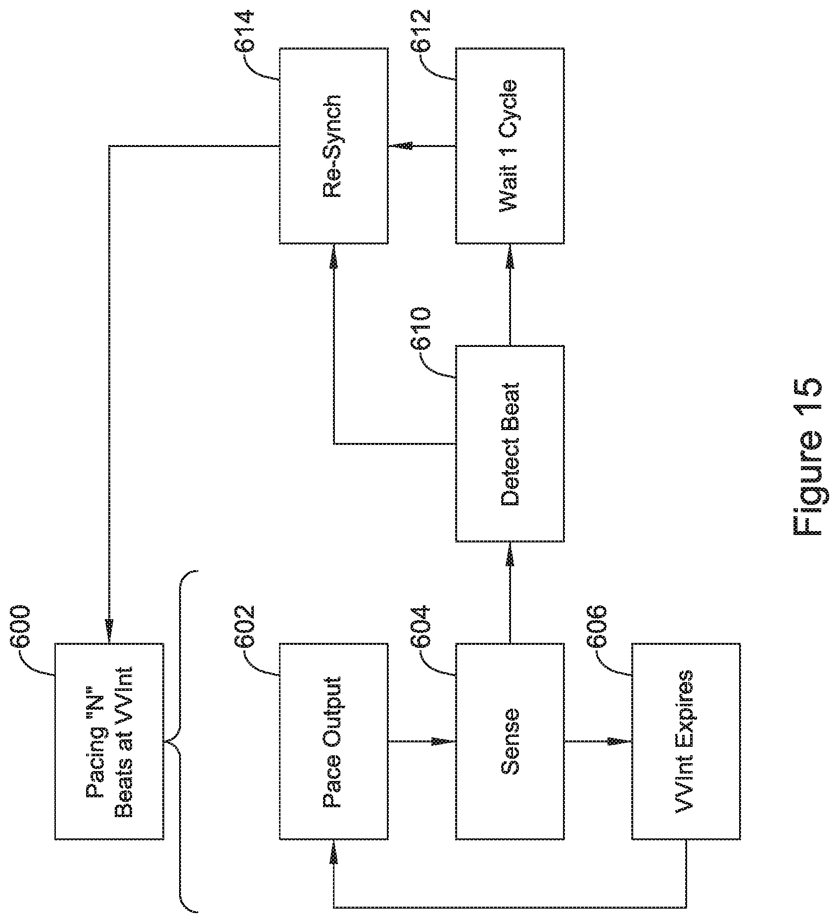
XML
uspto.report is an independent third-party trademark research tool that is not affiliated, endorsed, or sponsored by the United States Patent and Trademark Office (USPTO) or any other governmental organization. The information provided by uspto.report is based on publicly available data at the time of writing and is intended for informational purposes only.
While we strive to provide accurate and up-to-date information, we do not guarantee the accuracy, completeness, reliability, or suitability of the information displayed on this site. The use of this site is at your own risk. Any reliance you place on such information is therefore strictly at your own risk.
All official trademark data, including owner information, should be verified by visiting the official USPTO website at www.uspto.gov. This site is not intended to replace professional legal advice and should not be used as a substitute for consulting with a legal professional who is knowledgeable about trademark law.