Method and apparatus for processing uplink signal in cable broadcasting network
Baek , et al. January 12, 2
U.S. patent number 10,892,797 [Application Number 16/737,760] was granted by the patent office on 2021-01-12 for method and apparatus for processing uplink signal in cable broadcasting network. This patent grant is currently assigned to Electronics and Telecommunications Research Institute. The grantee listed for this patent is Electronics and Telecommunications Research Institute. Invention is credited to Myung-Sun Baek, Eun Hee Hyun, Joon Young Jung, Heung Mook Kim, Jin Hyuk Song.


| United States Patent | 10,892,797 |
| Baek , et al. | January 12, 2021 |
Method and apparatus for processing uplink signal in cable broadcasting network
Abstract
An apparatus and a method for processing an uplink signal of cable broadcasting network including: modulating uplink data to be transmitted to a broadcasting station which is located at an end of the cable broadcasting network into a plurality of symbols; performing a correlation-coding on the plurality of symbols; and outputting an analog radio frequency (RF) signal corresponding to the plurality of correlation-coded symbols are provided.
| Inventors: | Baek; Myung-Sun (Daejeon, KR), Song; Jin Hyuk (Daejeon, KR), Jung; Joon Young (Daejeon, KR), Kim; Heung Mook (Daejeon, KR), Hyun; Eun Hee (Daejeon, KR) | ||||||||||
|---|---|---|---|---|---|---|---|---|---|---|---|
| Applicant: |
|
||||||||||
| Assignee: | Electronics and Telecommunications
Research Institute (Daejeon, KR) |
||||||||||
| Family ID: | 1000005297777 | ||||||||||
| Appl. No.: | 16/737,760 | ||||||||||
| Filed: | January 8, 2020 |
Prior Publication Data
| Document Identifier | Publication Date | |
|---|---|---|
| US 20200220573 A1 | Jul 9, 2020 | |
Foreign Application Priority Data
| Jan 8, 2019 [KR] | 10-2019-0002458 | |||
| Current U.S. Class: | 1/1 |
| Current CPC Class: | H04B 3/02 (20130101); H04L 27/3405 (20130101); H04L 2012/6421 (20130101) |
| Current International Class: | H04B 3/02 (20060101); H04L 27/34 (20060101); H04L 12/64 (20060101) |
References Cited [Referenced By]
U.S. Patent Documents
| 5991308 | November 1999 | Fuhrmann |
| 6928656 | August 2005 | Addington |
| H2274 | May 2013 | Huttle |
| 8571146 | October 2013 | Eliaz |
| 2013/0343206 | December 2013 | Wilhoite |
| 2017/0279485 | September 2017 | Kim et al. |
| 2017/0279550 | September 2017 | Park et al. |
Attorney, Agent or Firm: William Park & Associates Ltd.
Claims
What is claimed is:
1. An apparatus for processing an uplink signal of cable broadcasting network, the apparatus comprising: a processor, a memory, and a communication unit, wherein the processor executes a program stored in the memory to perform: modulating uplink data to be transmitted to a broadcasting station which is located at an end of a cable broadcasting network into a plurality of symbols; performing a correlation-coding on the plurality of symbols; and outputting an analog radio frequency (RF) signal corresponding to the plurality of correlation-coded symbols and transferring the analog RF signal to a subscriber media IP access terminal in the cable broadcasting network through the communication unit.
2. The apparatus of claim 1, wherein when performing a correlation-coding on the plurality of symbols, the processor performs performing a correlation operation between the plurality of symbols and a previous symbol or a following symbol having a forward relationship or a backward relationship with the plurality of symbols.
3. The apparatus of claim 2, wherein: the correlation operation includes calculating a sum of a sequence represented by a product between the plurality of symbols and coefficients of the previous symbol or the following symbol.
4. The apparatus of claim 1, wherein: when modulating uplink data to be transmitted to a broadcasting station which is located at an end of a cable broadcasting network into a plurality of symbols, the processor performs: correcting an error of a bit stream for the uplink data; and modulating error-corrected bit stream into an M-ary Quadrature Amplitude Modulation (QAM) symbol.
5. The apparatus of claim 1, wherein: when outputting an analog radio frequency (RF) signal corresponding to the plurality of correlation-coded symbols, the processor performs: generating a pulse based on the plurality of correlation-coded symbols; and outputting the analog RF signal by up-converting a frequency of the pulse.
6. A method for processing an uplink signal of cable broadcasting network, the method comprising: modulating uplink data to be transmitted to a broadcasting station which is located at an end of the cable broadcasting network into a plurality of symbols; performing a correlation-coding on the plurality of symbols; and outputting an analog radio frequency (RF) signal corresponding to the plurality of correlation-coded symbols.
7. The method of claim 6, wherein: the performing a correlation-coding on the plurality of symbols includes performing a correlation operation between the plurality of symbols and a previous symbol or a following symbol having a forward relationship or backward relationship with the plurality of symbols.
8. The method of claim 7, wherein: the correlation operation includes calculating a sum of a sequence represented by a product between the plurality of symbols and coefficients of the previous symbol or the following symbol.
9. The method of claim 6, wherein: the modulating uplink data to be transmitted to a broadcasting station which is located at an end of a cable broadcasting network into a plurality of symbols includes: correcting an error of a bit stream for the uplink data; and modulating error-corrected bit stream into an M-ary Quadrature Amplitude Modulation (QAM) symbol.
10. The method of claim 6, wherein: the outputting an analog radio frequency (RF) signal corresponding to the plurality of correlation-coded symbols includes: generating a pulse based on the plurality of correlation-coded symbols; and outputting the analog RF signal by up-converting a frequency of the pulse.
11. A system for processing an uplink signal of cable broadcasting network, the system comprising: a cable modem (CM) device configured to generate a plurality of symbols by modulating uplink data to be transferred to a broadcasting station which is located at an end of the cable broadcasting network, create a correlation between the plurality of symbols by performing a correlation-coding on the plurality of symbols, and output an analog radio frequency (RF) signal based on the plurality of correlation-coded symbols; and a subscriber media IP access terminal configured to digitalize the analog RF signal and transfer an internet protocol (IP) signal including a digitalized RF signal to the broadcasting station.
12. The system of claim 11, wherein: the CM device is further configured to perform a correlation operation between the plurality of symbols and a previous symbol or a following symbol having a forward relationship or a backward relationship with the plurality of symbols.
13. The system of claim 12, wherein: the correlation operation includes calculating a sum of a sequence represented by a product between the plurality of symbols and coefficients of the previous symbol or the following symbol.
Description
CROSS-REFERENCE TO RELATED APPLICATION
This application claims priority to and the benefit of Korean Patent Application No. 10-2019-0002458 filed in the Korean Intellectual Property Office on Jan. 8, 2019, the entire contents of which are incorporated herein by reference.
BACKGROUND OF THE INVENTION
(a) Field of the Invention
This relates to a method and an apparatus for processing an uplink signal in a cable broadcasting network.
(b) Description of the Related Art
A cable broadcasting network connects broadcasting stations and subscribers through a hybrid fiber and coaxial (HFC) network. The HFC network includes optical cables and coaxial cables. From the broadcasting stations to buildings periphery to the subscriber, the content may be transferred by an optical signal through the optical cables, and then the content may be transferred to the subscriber by an electrical signal via the coaxial cables. The cable broadcasting network may provide a bidirectional service such as an Internet service and voice over internet protocol (VoIP) service through a cable modem (CM) device as well as a unidirectional service that simply transmits the broadcast signal.
Recently, the cable broadcasting network has evolved to minimize a use of the coaxial cables. That is, the optical cables are extended to a point very close to the subscriber's building, and even the optical cable may be directly connected to the subscribers home. For example, RFoG (Radio Frequency over Glass) technology is a technology that secures the stability of the broadcasting service and high-speed Internet at the same time by transmitting the cable broadcasting signal through the optical cables. The RFoG can transfer RF-type cable broadcasting signals in real time through fiber to the home (FTTH) rather than the conventional HFC network for the cable broadcasting. However, the RFoG is so expensive to deploy. The cost of an element (all-optical conversion component) used when an RFoG device located in the subscriber's home modulates an uplink RF signal into the optical signal occupies most of the implementation cost. The cost of replacing infrastructure is also high.
Several methods have been proposed to solve this cost problem. For example, in the RoIP (RF over IP) scheme, an analog RF signal transmitted from a subscriber terminal such as a set-top box (STB) may be converted into digital, and then transferred to an optical-based Internet protocol (IP) network. The uplink signal of the STB transmitted from the headend to the IP network may be converted into an analog RF signal and transmitted to a cable modem termination system (CMTS). However, at least four times signal sampling is required to prevent signal loss while the analog RF signal is digitalized. This excessive oversampling greatly increases throughput and reduces transfer rates.
The above information disclosed in this Background section is only for enhancement of understanding of the background and therefore it may contain information that does not form the prior art that is already known in this country to a person of ordinary skill in the art.
SUMMARY OF THE INVENTION
The present disclosure has been made in an effort to provide a method and an apparatus for processing an uplink signal in a cable broadcasting network.
According to an exemplary embodiment, an apparatus for processing an uplink signal of cable broadcasting network is provided. The apparatus includes: a processor, a memory, and a communication unit, wherein the processor executes a program stored in the memory to perform: modulating uplink data to be transmitted to a broadcasting station which is located at an end of a cable broadcasting network into a plurality of symbols; performing a correlation-coding on the plurality of symbols; and outputting an analog radio frequency (RF) signal corresponding to the plurality of correlation-coded symbols and transferring the analog RF signal to a subscriber media IP access terminal in the cable broadcasting network through the communication unit.
When performing a correlation-coding on the plurality of symbols, the processor may perform performing a correlation operation between the plurality of symbols and a previous symbol or a following symbol having a forward relationship or a backward relationship with the plurality of symbols.
The correlation operation may include calculating a sum of a sequence represented by a product between the plurality of symbols and coefficients of the previous symbol or the following symbol.
When modulating uplink data to be transmitted to a broadcasting station which is located at an end of a cable broadcasting network into a plurality of symbols, the processor may perform correcting an error of a bit stream for the uplink data; and modulating error-corrected bit stream into an M-ary Quadrature Amplitude Modulation (QAM) symbol.
When outputting an analog radio frequency (RF) signal corresponding to the plurality of correlation-coded symbols, the processor may performs generating a pulse based on the plurality of correlation-coded symbols; and outputting the analog RF signal by up-converting a frequency of the pulse.
According to another exemplary embodiment, a method for processing an uplink signal of cable broadcasting network is provided. The method includes: modulating uplink data to be transmitted to a broadcasting station which is located at an end of the cable broadcasting network into a plurality of symbols; performing a correlation-coding on the plurality of symbols; and outputting an analog radio frequency (RF) signal corresponding to the plurality of correlation-coded symbols.
The performing a correlation-coding on the plurality of symbols may include performing a correlation operation between the plurality of symbols and a previous symbol or a following symbol having a forward relationship or backward relationship with the plurality of symbols.
The correlation operation may include calculating a sum of a sequence represented by a product between the plurality of symbols and coefficients of the previous symbol or the following symbol.
The modulating uplink data to be transmitted to a broadcasting station which is located at an end of a cable broadcasting network into a plurality of symbols may include: correcting an error of a bit stream for the uplink data; and modulating error-corrected bit stream into an M-ary Quadrature Amplitude Modulation (QAM) symbol.
The outputting an analog radio frequency (RF) signal corresponding to the plurality of correlation-coded symbols may include: generating a pulse based on the plurality of correlation-coded symbols; and outputting the analog RF signal by up-converting a frequency of the pulse.
According to yet another exemplary embodiment, a system for processing an uplink signal of cable broadcasting network is provided. The system includes: a cable modem (CM) device configured to generate a plurality of symbols by modulating uplink data to be transferred to a broadcasting station which is located at an end of the cable broadcasting network, create a correlation between the plurality of symbols by performing a correlation-coding on the plurality of symbols, and output an analog radio frequency (RF) signal based on the plurality of correlation-coded symbols; and a subscriber media IP access terminal configured to digitalize the analog RF signal and transfer an internet protocol (IP) signal including a digitalized RF signal to the broadcasting station.
The CM device may be further configured to perform a correlation operation between the plurality of symbols and a previous symbol or a following symbol having a forward relationship or a backward relationship with the plurality of symbols.
The correlation operation may include calculating a sum of a sequence represented by a product between the plurality of symbols and coefficients of the previous symbol or the following symbol.
BRIEF DESCRIPTION OF THE DRAWINGS
FIG. 1 is a schematic diagram illustrating a transmission and reception system of a broadcasting RF signal based on an internet protocol according to an exemplary embodiment.
FIG. 2 is a block diagram illustrating an RF-based subscriber media IP access terminal according to an exemplary embodiment.
FIGS. 3A and 3B are a schematic diagram illustrating oversampling for digitalization of an uplink burst receiver according to an exemplary embodiment.
FIG. 4 is a block diagram illustrating a CM device according to an exemplary embodiment.
FIG. 5 is a flowchart illustrating an operation of the CM device according to an exemplary embodiment.
FIG. 6 is a schematic diagram illustrating a correlation encoder of the CM device according to an exemplary embodiment.
FIG. 7 is a block diagram illustrating a CM device according to another exemplary embodiment.
DETAILED DESCRIPTION OF THE EMBODIMENTS
In the following detailed description, only certain exemplary embodiments have been shown and described, simply by way of illustration. As those skilled in the art would realize, the described embodiments may be modified in various different ways, all without departing from the scope of the present disclosure. Accordingly, the drawings and description are to be regarded as illustrative in nature and not restrictive, and like reference numerals designate like elements throughout the specification.
FIG. 1 is a schematic diagram illustrating a transmission and reception system of a broadcasting RF signal based on an internet protocol according to an exemplary embodiment.
In FIG. 1, an uplink RF signal is digitalized and then transmitted in an internet protocol (IP) packet. An RF overlay scheme in which a signal is transmitted after being modulated into an optical signal through all-optical converters as in RFoG may be applied to a downlink RF signal.
Referring to FIG. 1, an RF-based subscriber media IP access terminal 200 which is located in the subscriber's home restores an optically modulated downlink RF signal received through an optical-based cable broadcasting network, and transmits the optically modulated downlink RF signal to an STB or a cable modem (CM) device through a coaxial cable. In addition, the RF-based subscriber media IP access terminal digitalizes the uplink RF signal output from the CM device 100 and transmits the digitalized uplink RF signal in the IP packet.
Transmission of the IP-based uplink RF signal may be performed as follows. When the CM device 100 outputs the uplink RF signal, the RF-based subscriber media IP access terminal may detect the uplink RF signal. When the uplink RF signal is detected, the RF-based subscriber media IP access terminal may perform an analog-to-digital conversion (ADC) to digitalize an analog RF signal and transmit an IP packet including the digitalized RF signal to the headend. The digitalized RF signal sent to the headend may be input to a modulator via internal devices (for example, routers, switches, and the like) of the headend connected to the IP network. The modulator located at the head end may perform digital to analog conversion (DAC) to restore the digitalized RF signal to an analog RF signal. The RF signal restored by the modulator then may be input to a CMTS. Accordingly, the CMTS may implement the same function as that the RF signal output from the CM device 100 may be directly transmitted to the CMTS may be implemented.
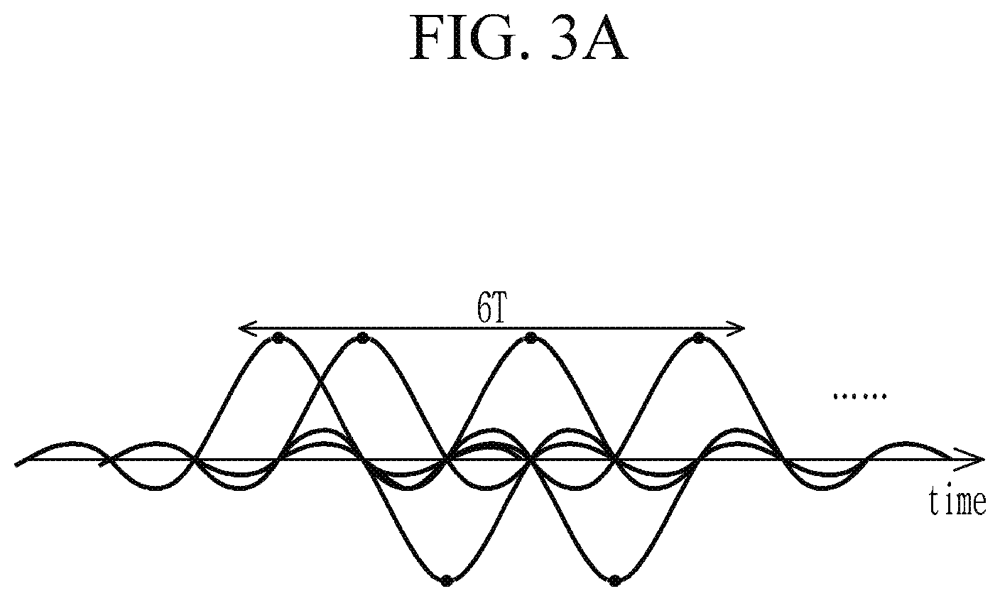
FIG. 2 is a block diagram illustrating an RF-based subscriber media IP access terminal according to an exemplary embodiment, and FIGS. 3A and 3B are a schematic diagram illustrating oversampling for digitalization of an uplink burst receiver according to an exemplary embodiment.
Referring to FIG. 2, the RF-based subscriber media IP access terminal 200 according to an exemplary embodiment includes an uplink burst receiver 210, a synchronization timing analyzer 220 and a synchronizer 230.
The uplink burst receiver 210 may receive an RF signal transmitted from the CM device and check the presence of an analog RF signal. When the analog RF signal from the CM exists, the uplink burst receiver 210 may perform down-conversion and digitalization on the analog RF signal, and transmit the digitalized RF signal to the synchronizer 230.
The synchronization timing analyzer 220 may transmit a synchronization message for downlink data transmitted from the CMTS to the synchronizer 230.
The synchronizer 230 may synchronize a clock of the digitalized RF signal by using the synchronization message for the downlink data and generate a band allocation time. The clocked uplink RF signal may be transferred to the CMTS in the form of an IP frame via the buffer 240. In this case, when the uplink burst receiver 210 digitalizes the uplink analog RF signal, the uplink burst receiver 210 may perform at least four times or more oversampling per symbol to prevent loss of the signal. Referring to FIG. 3A, a sampling scheme in which one sample is extracted per symbol is shown, and referring to FIG. 3B, an oversampling scheme in which 4 samples are extracted per symbol is shown. When four times oversampling is performed as in (b), the amount of data to be processed is increased by four times and the amount of data to be transmitted is increased by four times, therefore, the transmission rate of the system is reduced. Hereinafter, a method for lowering the sampling rate of oversampling by providing correlation between symbols is described.
FIG. 4 is a block diagram illustrating a CM device according to an exemplary embodiment, FIG. 5 is a flowchart illustrating an operation of the CM device according to an exemplary embodiment, and FIG. 6 is a schematic diagram illustrating a correlation encoder of the CM device according to an exemplary embodiment.
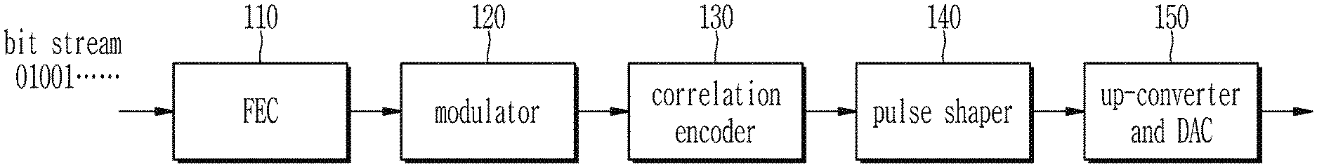
Referring to FIG. 4, the CM device 100 according to an exemplary embodiment includes a forward error corrector (FEC) 110, a modulator 120, a correlation encoder 130, a pulse shaper 140, an up-converter and a DAC 150.
Referring to FIG. 5, a bit stream representing uplink data to be transmitted to the CMTS is error-corrected by the FEC 110 (S110), and then, modulated by the modulator 120 (S120). The modulator 120 may perform M-ary modulation and may, for example, modulate the bit stream encoded by the FEC 110 into Quadrature Amplitude Modulation (QAM) symbols.
The correlation encoder 130 may provide correlation to the M-ary QAM (M-QAM) modulated symbol output from the modulator 120 by performing a correlation-coding on the M-ary modulated symbols (S130).
The pulse generator 140 may generate a pulse based on the modulated symbols in which the correlation is given (S140). In this case, the pulse generator 140 may perform a function of a band stop filter.
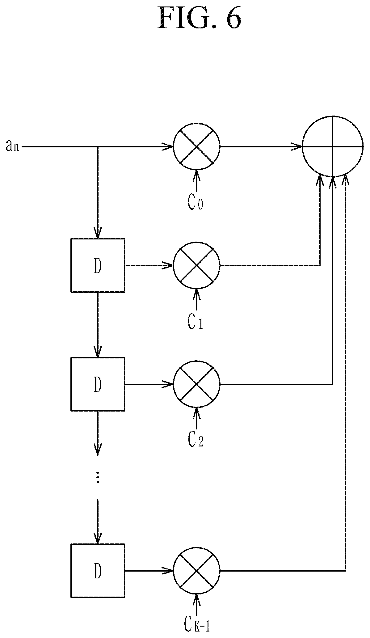
The up-converter and the DAC 150 may up-convert a frequency of the pulse and output an analog RF signal (S150). The correlation encoder 130 according to an exemplary embodiment may perform the correlation-coding by using a polynomial of Equation 1 below. In Equation 1, D may mean a delay. 1D+D.sup.2+ . . . +D.sup.K-1 [Equation 1]
Referring to FIG. 6, a.sub.n is an n-th transmitted M-QAM modulated symbol. When a length of a frame including the plurality of symbols is N, the modulated symbol a may be represented by Equation 2 below. a=[a.sub.0a.sub.1 . . . a.sub.n . . . a.sub.N-1] [Equation 2]
According to an exemplary embodiment, the correlation coding may be performed to provide correlation between previous symbols and following symbols by the correlation operation of Equation 3.
.times..times..times. ##EQU00001##
In Equation 3, c.sub.i is a coefficient of i-th delayed symbol. Referring to Equation 3, the correlation-coded modulation symbol b.sub.n corresponding to the n-th transmitted modulation symbol a.sub.n may be determined by summing a sequence represented as a product between the modulated symbol a.sub.n and the coefficient c.sub.i of the i-th delayed modulation symbol. In other words, the modulated symbol b.sub.n may include the correlation between the modulated symbol a.sub.n and the previous symbol or the following symbol of the modulated symbol a.sub.n. The correlation coded modulation symbol b output from the correlation encoder 130 may be expressed by Equation 4 below. b=[b.sub.0b.sub.1 . . . b.sub.n . . . b.sub.N-1] [Equation 4]
The correlation coded modulation symbol b may be then converted into an RF signal having an appropriate band via the band stop filter and then be transmitted. The modulated symbol on which the correlation-coding operation is performed may include information of the previous symbol.
Subsequently, when the CMTS detects an uplink stream corresponding to the modulated symbol a which is an original signal from an uplink stream corresponding to the modulated symbol b, an additional operation may be required. For an operation for detecting a stream corresponding to an original symbol from the correlation-coded stream, various technique such as MLSE (Maximum Likelihood Sequence Estimation), or Trellis-based Viterbi, or BCJR (Bahl, Cocke, Jelinek, and Raviv) may be used. These detection techniques may be rather complicated and require a large amount of computation, but it can be applied without difficulty since the CMTS, which is a broadcasting company's headend equipment, may be added.
According to the exemplary embodiment, since information of the plurality of symbols is included in one transmission pulse corresponding to one modulated symbol, a large amount of information may be extracted only by the relatively low-degree of sampling. In other words, since the sampling rate for the oversampling performed when digitalizing the analog RF signal can be reduced, the transmission rate of the system can be increased.
FIG. 7 is a block diagram illustrating a CM device according to another exemplary embodiment.
The CM device according to another exemplary embodiment may be implemented as a computer system, for example a computer readable medium. Referring to FIG. 7, a computer system 700 may include at least one of processor 710, a memory 730, an input interface unit 750, an output interface unit 760, and storage 740. The computer system 700 may also include a communication unit 720 coupled to a network. The processor 710 may be a central processing unit (CPU) or a semiconductor device that executes instructions stored in the memory 730 or storage 740. The memory 730 and the storage 740 may include various forms of volatile or non-volatile storage media. For example, the memory may include read only memory (ROM) 731 or random access memory (RAM) 732. In the exemplary embodiment of the present disclosure, the memory may be located inside or outside the processor, and the memory may be coupled to the processor through various means already known.
Thus, the embodiments may be embodied as a computer-implemented method or as a non-volatile computer-readable medium having computer-executable instructions stored thereon. In the exemplary embodiment, when executed by a processor, the computer-readable instructions may perform the method according to at least one aspect of the present disclosure. The communication unit 720 may transmit or receive a wired signal or a wireless signal.
On the contrary, the embodiments are not implemented only by the apparatuses and/or methods described so far, but may be implemented through a program realizing the function corresponding to the configuration of the embodiment of the present disclosure or a recording medium on which the program is recorded. Such an embodiment can be easily implemented by those skilled in the art from the description of the embodiments described above. Specifically, methods (e.g., network management methods, data transmission methods, transmission schedule generation methods, etc.) according to embodiments of the present disclosure may be implemented in the form of program instructions that may be executed through various computer means, and be recorded in the computer-readable medium. The computer-readable medium may include program instructions, data files, data structures, and the like, alone or in combination. The program instructions to be recorded on the computer-readable medium may be those specially designed or constructed for the embodiments of the present disclosure or may be known and available to those of ordinary skill in the computer software arts. The computer-readable recording medium may include a hardware device configured to store and execute program instructions. For example, the computer-readable recording medium can be any type of storage media such as magnetic media like hard disks, floppy disks, and magnetic tapes, optical media like CD-ROMs, DVDs, magneto-optical media like floptical disks, and ROM, RAM, flash memory, and the like. Program instructions may include machine language code such as those produced by a compiler, as well as high-level language code that may be executed by a computer via an interpreter, or the like.
While this disclosure has been described in connection with what is presently considered to be practical example embodiments, it is to be understood that this disclosure is not limited to the disclosed embodiments, but, on the contrary, is intended to cover various modifications and equivalent arrangements included within the spirit and scope of the appended claims.
* * * * *
D00000
D00001
D00002
D00003
D00004
D00005
D00006
D00007
D00008
M00001
XML
uspto.report is an independent third-party trademark research tool that is not affiliated, endorsed, or sponsored by the United States Patent and Trademark Office (USPTO) or any other governmental organization. The information provided by uspto.report is based on publicly available data at the time of writing and is intended for informational purposes only.
While we strive to provide accurate and up-to-date information, we do not guarantee the accuracy, completeness, reliability, or suitability of the information displayed on this site. The use of this site is at your own risk. Any reliance you place on such information is therefore strictly at your own risk.
All official trademark data, including owner information, should be verified by visiting the official USPTO website at www.uspto.gov. This site is not intended to replace professional legal advice and should not be used as a substitute for consulting with a legal professional who is knowledgeable about trademark law.