Dense high-speed scintillator material of low afterglow
Ferrand , et al. January 12, 2
U.S. patent number 10,890,670 [Application Number 16/400,195] was granted by the patent office on 2021-01-12 for dense high-speed scintillator material of low afterglow. This patent grant is currently assigned to SAINT-GOBAIN CRISTAUX ET DETECTEURS. The grantee listed for this patent is SAINT-GOBAIN CRISTAUX ET DETECTEURS. Invention is credited to Pieter Dorenbos, Bernard Ferrand, Ludivine Pidol, Bruno Viana.


| United States Patent | 10,890,670 |
| Ferrand , et al. | January 12, 2021 |
Dense high-speed scintillator material of low afterglow
Abstract
The invention relates to an inorganic scintillator material of formula Lu.sub.(2-y)Y.sub.(y-z-x)Ce.sub.xM.sub.zSi.sub.(1-v)M'.sub.vO.sub.5, in which: M represents a divalent alkaline earth metal and M' represents a trivalent metal, (z+v) being greater than or equal to 0.0001 and less than or equal to 0.2; z being greater than or equal to 0 and less than or equal to 0.2; v being greater than or equal to 0 and less than or equal to 0.2; x being greater than or equal to 0.0001 and less than 0.1; and y ranging from (x+z) to 1. In particular, this material may equip scintillation detectors for applications in industry, for the medical field (scanners) and/or for detection in oil drilling. The presence of Ca in the crystal reduces the afterglow, while stopping power for high-energy radiation remains high.
| Inventors: | Ferrand; Bernard (Voreppe, FR), Viana; Bruno (Montgeron, FR), Pidol; Ludivine (Cachan, FR), Dorenbos; Pieter (Gm Rijswijk, NL) | ||||||||||
|---|---|---|---|---|---|---|---|---|---|---|---|
| Applicant: |
|
||||||||||
| Assignee: | SAINT-GOBAIN CRISTAUX ET
DETECTEURS (Courbevoie, FR) |
||||||||||
| Family ID: | 1000005295991 | ||||||||||
| Appl. No.: | 16/400,195 | ||||||||||
| Filed: | May 1, 2019 |
Prior Publication Data
| Document Identifier | Publication Date | |
|---|---|---|
| US 20190257958 A1 | Aug 22, 2019 | |
Related U.S. Patent Documents
| Application Number | Filing Date | Patent Number | Issue Date | ||
|---|---|---|---|---|---|
| 15358341 | Nov 22, 2016 | 10324198 | |||
| 14039888 | Jan 3, 2017 | 9534170 | |||
| 13214648 | Nov 5, 2013 | 8574458 | |||
| 12622881 | Oct 11, 2011 | 8034258 | |||
| 11573323 | Jan 26, 2010 | 7651632 | |||
| PCT/FR2005/050658 | Aug 8, 2005 | ||||
Foreign Application Priority Data
| Aug 9, 2004 [FR] | 04 51815 | |||
| Current U.S. Class: | 1/1 |
| Current CPC Class: | C09K 11/745 (20130101); G01T 1/2023 (20130101); G21K 4/00 (20130101); C09K 11/7774 (20130101); A61B 6/4258 (20130101) |
| Current International Class: | C09K 11/77 (20060101); G01T 1/202 (20060101); C09K 11/74 (20060101); G21K 4/00 (20060101); A61B 6/00 (20060101) |
References Cited [Referenced By]
U.S. Patent Documents
| 4747973 | May 1988 | Cusano et al. |
| 4783596 | November 1988 | Riedner et al. |
| 5003181 | March 1991 | Morlotti |
| 5998925 | December 1999 | Shimizu et al. |
| 6093347 | July 2000 | Lynch et al. |
| 6278832 | August 2001 | Zagumennyl et al. |
| 6323489 | November 2001 | McClellan |
| 6437336 | August 2002 | Pauwels et al. |
| 6498828 | December 2002 | Jiang |
| 6624420 | September 2003 | Chai et al. |
| 6921901 | July 2005 | Chai et al. |
| 7102135 | September 2006 | Lecoq |
| 7132060 | November 2006 | Zagumennyl et al. |
| 7138074 | November 2006 | Nakamura |
| 7166845 | January 2007 | Chai |
| 7180068 | February 2007 | Brecher et al. |
| 7531036 | May 2009 | Shimura et al. |
| 7618491 | November 2009 | Kurata et al. |
| 7651632 | January 2010 | Ferrand et al. |
| 7692153 | April 2010 | Shimizu et al. |
| 7749323 | July 2010 | Shimura et al. |
| 8034258 | October 2011 | Ferrand et al. |
| 8062419 | November 2011 | Andreaco et al. |
| 8158948 | April 2012 | Chou |
| 8278624 | October 2012 | Koschan et al. |
| 8394195 | March 2013 | Andreaco et al. |
| 8574458 | November 2013 | Ferrand et al. |
| 8617422 | December 2013 | Koschan et al. |
| 8999281 | April 2015 | Kurata et al. |
| 9328288 | May 2016 | Cohen et al. |
| 9534170 | January 2017 | Ferrand et al. |
| 10094048 | October 2018 | Chou |
| 10324198 | June 2019 | Ferrand |
| 2002/0144640 | October 2002 | Andreaco et al. |
| 2003/0020044 | January 2003 | Lyons et al. |
| 2003/0062465 | April 2003 | Pauwels et al. |
| 2003/0159643 | August 2003 | Sumiya et al. |
| 2004/0108492 | June 2004 | Derenzo et al. |
| 2004/0200964 | October 2004 | Lefaucheur et al. |
| 2004/0245479 | December 2004 | Misawa et al. |
| 2005/0082484 | April 2005 | Srivastava et al. |
| 2005/0104000 | May 2005 | Kindem et al. |
| 2005/0211906 | September 2005 | Tonami et al. |
| 2006/0086311 | April 2006 | Zagumennyi |
| 2006/0266277 | November 2006 | Usui et al. |
| 2006/0288926 | December 2006 | Kurata et al. |
| 2008/0089824 | April 2008 | Shimura et al. |
| 2010/0078595 | April 2010 | Eriksson et al. |
| 2010/0327227 | December 2010 | Kurata et al. |
| 2012/0126171 | May 2012 | Andreaco et al. |
| 2014/0061537 | March 2014 | Zagumennyi |
| 2014/0291580 | October 2014 | Zagumennyi |
| 2015/0069298 | March 2015 | Kurata et al. |
| 2016/0002529 | January 2016 | Blahuta et al. |
| 2016/0252631 | September 2016 | Blahuta et al. |
| 1926218 | Mar 2007 | CN | |||
| 102477580 | May 2012 | CN | |||
| 1926218 | Dec 2012 | CN | |||
| 105986320 | Oct 2016 | CN | |||
| 108186041 | Jun 2018 | CN | |||
| 19950087 | May 2000 | DE | |||
| 0 097 296 | Jan 1987 | EP | |||
| 0 795 631 | Sep 1997 | EP | |||
| 1 028 154 | Aug 2000 | EP | |||
| 1466955 | Oct 2004 | EP | |||
| 2-300696 | Dec 1990 | JP | |||
| 6-287553 | Oct 1994 | JP | |||
| 2000178554 | Jun 2000 | JP | |||
| 2001-524163 | Nov 2001 | JP | |||
| 2003-253255 | Sep 2003 | JP | |||
| 2004-300418 | Oct 2004 | JP | |||
| 2004-339506 | Dec 2004 | JP | |||
| 2006-83275 | Mar 2006 | JP | |||
| 2006-199727 | Aug 2006 | JP | |||
| 2006-257199 | Sep 2006 | JP | |||
| 2007-1849 | Jan 2007 | JP | |||
| 2007-1850 | Jan 2007 | JP | |||
| 2007-16197 | Jan 2007 | JP | |||
| WO-2005042812 | May 2005 | WO | |||
| WO-2015185988 | Dec 2015 | WO | |||
Other References
|
Zavartsev, et al, "Czochralski growth and characterisation of large Ce3 + :Lu2SiO5 Single crystals co-doped with Mg.sup.2 + or Ca.sup.2 + or Tb3 + for scintillators", Journal of Crystal Growth, vol. 275, No. 1-2, pp. e2167-e2171 (2005). cited by applicant . Office Action dated Oct. 23, 2012, in Japanese Patent Application No. 2007-525327 (with English translation). cited by applicant . Maria D. Alba et at, "Formation of High-Temperature Lutetium Disilicate from Lutetium-Saturated Aluminosilicates in Mild Conditions. Incorporation of Si and Al XAS Techniques to the Study of These Systems", J. Phys. Chem., 100, 1996, pp. 19559-19567. cited by applicant . Michael E. Fleet et at., "The Structure of NaCa2LuSi2O7F2, A Synthetic Phase of the Cuspidine Group", The Canadian Mineralogist, vol. 33, 1995, pp. 879-884. cited by applicant. |
Primary Examiner: Taningco; Marcus H
Attorney, Agent or Firm: Element IP, PLC
Parent Case Text
CROSS REFERENCE TO RELATED APPLICATIONS
This application is a continuation application of prior U.S. patent application Ser. No. 15/358,341 filed Nov. 22, 2016, which is a continuation of prior U.S. patent application Ser. No. 14/039,888 filed Sep. 27, 2013; now U.S. Pat. No. 9,534,170, which is a continuation application of prior U.S. patent application Ser. No. 13/214,648 filed Aug. 22, 2011; now U.S. Pat. No. 8,574,458, which is a divisional of Ser. No. 12/622,881 filed on Nov. 20, 2009; now U.S. Pat. No. 8,034,258, which is a divisional application of prior U.S. patent application Ser. No. 11/573,323 which is a National Stage of PCT/FR05/50658 filed on Aug. 8, 2005; now U.S. Pat. No. 7,651,632, which claims the benefit of priority under 35 U.S.C .sctn. 119 from French Patent Application No. 045181.5, filed Aug. 9, 2004, the entire contents of which are incorporated herein by reference.
Claims
The invention claimed is:
1. A method for preparing a single-crystal scintillator material comprising Lu, Si, O, and M or M' in which M represents a divalent alkaline earth metal ion and M' represents a trivalent metal, the method comprising: growing the single crystal according to the Czochralski method.
2. The method according to claim 1, wherein the single-crystal scintillator material comprises Y.
3. The method according to claim 1, wherein M or M' substantially reduces the afterglow.
4. The method according to claim 1, wherein M is present and M is at least one selected from the group consisting of Ca, Mg, and Sr.
5. The method according to claim 1, wherein M' is present and M' is at least one selected from the group consisting of Al, Ga, and In.
6. The method according to claim 1, wherein M is introduced in said scintillator material for substituting for a trivalent rare-earth ion, or M' is introduced in said scintillator material for substituting for a tetravalent silicon atom.
7. The method according to claim 1, wherein the single-crystal scintillator material has a formula of: Lu.sub.(2-y)Y.sub.(y-z-x)Ce.sub.xM.sub.zSi.sub.(1-v)M'.sub.vO.sub.5, wherein: (z+v) is greater than or equal to 0.0001 and less than or equal to 0.2; z is greater than 0 and less than or equal to 0.2; v is greater than or equal to 0 and less than or equal to 0.2; x is greater than or equal to 0.0001 and less than 0.1; and y is from (x+z) to 1.
8. The method according to claim 7, wherein (z+v) is greater than or equal to 0.0002.
9. The method according to claim 7, wherein (z+v) is less than or equal to 0.05.
10. The method according to claim 7, wherein (z+v) is less than or equal to 0.01.
11. The method according to claim 7, wherein (z+v) is less than 0.001.
12. The method according to claim 7, wherein x is greater than 0.0001 and less than 0.001.
13. The method according to claim 1, wherein an atomic ratio of a sum of M and M' to O ranges from 0.00002 to 0.04.
14. A method, comprising: performing a medical scan with a scintillator system comprising a scintillation detector comprising an inorganic scintillator material comprising Lu, Si, O, and M or M' in which M represents a divalent alkaline earth metal ion and M' represents a trivalent metal.
15. The method of claim 14, wherein the scintillation detector is a component of a computed tomography scanner.
16. The method of claim 15, wherein the computed tomography scanner is coupled to a positron emission tomography scanner.
17. The method of claim 14, wherein M or M' substantially reduces the afterglow from cerium ion emission between about 350 nm and 450 nm.
18. The method of claim 14, wherein the scintillation material is a single-crystal material which is grown in the presence of M or M' in the melt or the scintillation material is a single-crystal material which is grown by the Czochralski method in the presence of M or M' in the melt.
19. The method of claim 14, wherein the scintillator system is a continuous acquisition scintillator system.
20. The method of claim 14, wherein the scintillator system is a positron emission tomography system having time of flight measurement and optionally emission tomography.
Description
BACKGROUND OF THE INVENTION
The invention relates to scintillator materials, to a manufacturing process for obtaining them and to the use of said materials, especially in gamma-ray and/or X-ray detectors.
Scintillator materials are widely used in detectors for gamma rays, X-rays, cosmic rays and particles having an energy of the order of 1 keV and also above this value.
A scintillator material is a material that is transparent in the scintillation wavelength range, which responds to incident radiation by emitting a light pulse.
It is possible to manufacture from such materials, which are generally single crystals, detectors in which the light emitted by the crystal that the detector contains is coupled to a light detection means and produces an electrical signal proportional to the number of light pulses received and to their intensity. Such detectors are used in particular in industry to measure thickness and grammage or coating weight, and in the fields of nuclear medicine, physics, chemistry and oil research.
One family of known scintillator crystals that is used is that of cerium-doped lutetium silicates. Cerium-doped Lu.sub.2SiO.sub.5 is disclosed in U.S. Pat. No. 4,958,080, and the U.S. Pat. No. 6,624,420 discloses Ce.sub.2x(Lu.sub.1-yY.sub.y).sub.2(1-x)SiO.sub.5. Finally, U.S. Pat. No. 9,437,336 relates to compositions of the Lu.sub.2(1-x)M.sub.2xSi.sub.2O.sub.7 type, where M is at least partly cerium. These various scintillator compositions all have in common a high stopping power for high-energy radiation and give rise to intense light emission with very rapid light pulses.
A desirable additional property is to reduce the amount of light emitted after the incident radiation stops (i.e. delayed luminescence or afterglow). Physically, this phenomenon, well known to those skilled in the art, is explained by the presence of electron traps in the crystallographic structure of the material. The phenomenon of scintillation relies on the photoelectric effect, which creates an electron-hole pair in the scintillator material. Upon recombination on an active site (a Ce.sup.3+ site in the aforementioned scintillators), the electron emits photons via a process that generally takes place in much less than one microsecond. The aforementioned scintillators, which are particularly rapid, result in a pulse duration that decreases with a first-order exponential constant of around 40 ns. However, the trapped electrons do not generate light, but their detrapping by thermal excitation (including at room temperature) gives rise to photon emission--the afterglow--, which still remains measurable after times of greater than one second.
This phenomenon may be unacceptable in applications in which it is desired to isolate each pulse, using very short windowing. This is particularly the case with CT (computed tomography) applications (scanners) that are well known in the medical or industrial sectors. When the CT system is coupled to a PET (Positron Emission Tomography) scanner, which is becoming the standard in industry, the poorer resolution of the CT affects the performance of the entire system and therefore the capability of the clinician to interpret the result of the complete PET/CT system. Afterglow is known to be completely unacceptable for these applications.
Compositions of the lutetium silicates type, disclosed in U.S. Pat. No. 4,958,080 (of the LSO:Ce type, using the notation of those skilled in the art) and U.S. Pat. No. 6,624,420 (of the LYSO:Ce type) are known to generate a significant afterglow. In contrast, the compositions disclosed in U.S. Pat. No. 6,437,336 (of the LPS:Ce type) have the advantage of a much weaker afterglow. These results are given for example by L. Pidol, A. Kahn-Harari, B. Viana, B. Ferrand, P. Dorenbos, J. de Haas, C. W. E. van Eijk and E. Virey in "Scintillation properties of Lu.sub.2Si.sub.2O.sub.7:Ce.sup.3+, a fast and dense scintillator crystal", Journal of Physics: Condensed Matter, 2003, 15, 2091-2102. The curve shown in FIG. 1 is extracted from this article and represents the amount of light detected in the form of the number of events (or counts) per mg of scintillator material as a function of time, under X-ray excitation for a few hours. The LPS:Ce composition gives a significantly better result in terms of afterglow.
The behavior of LYSO is very similar to that of LSO from this standpoint. The reduction in this afterglow forms the subject of the present application.
The afterglow property may be demonstrated more fundamentally by thermoluminescence (see S. W. S. McKeever "Thermoluminescence of solids", Cambridge University Press (1985)). This characterization consists in thermally exciting a specimen after irradiation and measuring the light emission. A light peak close to room temperature at 300 K corresponds to an afterglow of greater or lesser magnitude depending on its intensity (detrapping). A peak at a higher temperature corresponds to the existence of traps that are deeper but less susceptible to thermal excitation at room temperature. This is illustrated in FIG. 2, extracted from the aforementioned article by L. Pidol et al., which shows, in another way, the advantage of a composition of the LPS type in terms of afterglow.
However, compositions of the LPS type have the drawback of a lower stopping power than those of the LSO or LYSO type. This situation stems simply from the average atomic number of the compound and from the density of the associated phase.
BRIEF SUMMARY OF THE INVENTION
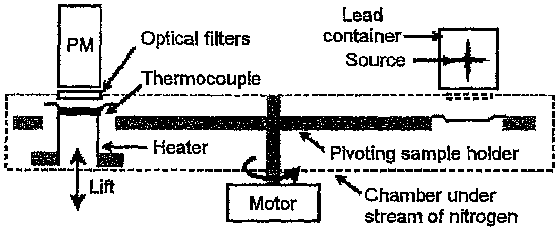
Thermoluminescence measurements may be carried out using an automated TL-DA-15 instrument, manufactured by RISO (Denmark), shown schematically in FIG. 3. The heater, the thermocouple and a "lift", allowing the specimen to be positioned, are in alignment with the photomultiplier (PM) and with optical filters. Inside the analysis chamber, which is under a stream of nitrogen, a pivoting table (pivoting specimen holder) actuated by a motor is able to position the specimen either in front of the radioactive source (placed in a lead container) for the irradiation step, or between the heater and the photomultiplier for the thermoluminescence measurements. Before each measurement, the crystals, which are about 1 mm in thickness, are heated for a few minutes to 672 K. Next, they are irradiated and then the thermoluminescence curves are recorded under a stream of nitrogen, with a constant heating rate between 313 and 672 K. Measurements at higher temperatures are not possible because of the black body radiation ("black body radiation" is the light spontaneously emitted by a substance that is heated to incandescence). Each curve is normalized with respect to the mass of product.
In our case, the emission that interests us is that from the cerium ion, between about 350 and 450 nm. We have chosen matched filters (HA3 and 7-59) at the entry of the photomultiplier. For quantitative measurements, the irradiation takes place in situ by a .sup.90Sr/.sup.90Y .beta.-source delivering a dose of 3.6 gray/h in air. The parameters that can be varied during the TL (thermoluminescence) measurements are the dose (irradiation time, here 20 s) and the heating rate (here, 0.5 K/s).
The Applicant has discovered that the addition of a divalent alkaline earth metal M and/or of a trivalent metal M' to an LYSO-type composition very substantially reduces the afterglow. In particular, M may be Ca, Mg or Sr (in divalent cation form). In particular, M' may be Al, Ga or In (in trivalent cation form). The element M substitutes for Y or Lu and the element M' substitutes for Si.
BRIEF DESCRIPTION OF DRAWINGS
FIG. 1 is a diagram showing the amount of light detected in the form of the number of events (or counts) per mg of scintillator material as a function of time, under X-ray excitation for a few hours.
FIG. 2 is a diagram showing the amount of light measured as a function of temperature.
FIG. 3 is a schematic diagram of an automated TL-DA-15 instrument, manufactured by RISO (Denmark).
FIG. 4 is a diagram comparing the afterglow values of compositions 1 and 2 with a conventional LSO.
DETAILED DESCRIPTION OF THE INVENTION
Surprisingly, the products according to the invention, thanks to the introduction of M, especially Ca, reduce the afterglow without affecting the density within the proportions considered.
The scintillator material according to the invention is of formula: Lu.sub.(2-y)Y.sub.(y-z-x)Ce.sub.xM.sub.zSi.sub.(1-v)M'.sub.vO.sub.5 (Formula 1) in which:
M represents a divalent alkaline earth metal, such as Ca, Mg or Sr, and M' represents a trivalent metal, such Al, Ga or In, (z+v) being greater than or equal to 0,0001 and less than or equal to 0.2; z being greater than or equal to 0 and less than or equal to 0.2; v being greater than or equal to 0 and less than or equal to 0.2; x being greater than or equal to 0.0001 and less than 0.1; and y ranging from (x+z) to 1.
Preferably, (z+v) is greater than or equal to 0.0002.
Preferably, (z+v) is less than or equal to 0.05 and more preferably less than or equal to 0.01, and even less than 0.001.
Preferably, x is greater than 0.0001 and less than 0.001.
In particular, v may be zero (absence of M'), in which case z is at least 0.0001.
In particular, the scintillator material according to the invention may be such that v is zero. The scintillator material according to the invention may also be such that M is Ca, which corresponds to a particularly suitable composition. The combination of v being zero with M being Ca as particularly suitable. The composition according to the invention then has the following formula: Lu.sub.(2-y)Y.sub.(y-z-x)Ce.sub.xCa.sub.2SiO.sub.5 (Formula II)
The scintillator material according to the invention may in particular also be such that z is zero. The scintillator material according to the invention may in particular also be such that M' is Al. The combination of z being zero with M' being Al is particularly suitable. The composition according to the invention then has the following formula: Lu.sub.(2-y)Y.sub.(y-x)Ce.sub.xAl.sub.vSi.sub.(1-v)O.sub.5 (Formula III)
The molar content of the element 0 is substantially five times that of (Si+M'), it being understood that this value may vary by about .+-.2%.
The scintillator material according to the invention can be obtained in the form of a single crystal or a single crystal by Czochralski growth.
The invention also relates to the use of the scintillator material according to the invention as a component of a radiation detector, in particular a gamma-ray and/or X-ray detector, especially in CT (Computed Tomography) scanners.
The invention also relates to the use of the scintillator material according to the invention as a component of a scintillation detector, especially for applications in industry, for the medical field and/or for detection in oil drilling. In particular, this involves any scintillator system with continuous acquisition (which include CT tomography). Also involved is any scintillator system of the positron emission tomography type, especially with time-of-flight measurement), optionally combined with emission tomography.
Without the Applicant being tied down to any particular theoretical argument, it is assumed that the introduction of a divalent alkaline earth metal ion M substituting for a trivalent rare-earth ion, or of a trivalent metal ion M' substituting for a tetravalent silicon atom, creates a positive charge deficit that limits the trapping of electrons responsible for the afterglow.
EXAMPLES
Three LYSO:Ce single crystals 1 inch in diameter were produced using the Czochralski method under conditions identical to those described in the aforementioned patents. To do this, raw materials corresponding to the following compositions were used:
Control (with no Ca):
Lu.sub.1.8Y.sub.0.1978Ce.sub.0.0022SiO.sub.4.9961
Composition 1:
Lu.sub.1.8Y.sub.0.1778Ca.sub.0.02Ce.sub.0.0022SiO.sub.4.9961
Composition 2:
Lu.sub.1.8Y.sub.0.1878Ca.sub.0.01Ce.sub.0.0022SiO.sub.4.9961
The charges were prepared from the corresponding oxides (Ca, Ce, Lu, Y oxides) so as to obtain the desired formulae. The actual Ce and Ca concentrations in the final crystal were lower than those introduced via the raw materials through segregation during crystal growth.
The single crystals finally obtained, of formula Lu.sub.(2-y)Y.sub.(y-z-x)Ce.sub.xCa.sub.2SiO.sub.5, had the following compositions at the top of the specimen:
TABLE-US-00001 Control (no Ca) Composition 1 Composition 2 x 0.00026 0.00031 0.00036 y 0.095 0.095 0.095 z 0 0.00041 0.00023
Composition 1 gave a significantly lower afterglow than the control composition (of the conventional LYSO type) and an estimated light level of 20 000 photons/MeV under excitation by a .sup.137Cs gamma-ray source, i.e. slightly less than the LPS composition (26 000 photons/MeV), the LYSO composition (34 000 photons/MeV) and the LSO composition (about 28 000 photons/MeV). Such a light level is far from unacceptable for most applications. Bismuth germanate (Bi.sub.4Ge.sub.3O.sub.12), very widely used, emits only 9 000 photons/MeV. Overall, composition 1 has as much stopping power as an LYSO-type composition without significantly losing out in terms of light level, while still significantly reducing the afterglow.
Composition 2 is even more advantageous, with a still lower afterglow and a light yield of 27 000 photons/MeV.
FIG. 4 compares the afterglow values of compositions 1 and 2 with a conventional LSO (the control).
* * * * *
D00000
D00001
D00002
D00003
XML
uspto.report is an independent third-party trademark research tool that is not affiliated, endorsed, or sponsored by the United States Patent and Trademark Office (USPTO) or any other governmental organization. The information provided by uspto.report is based on publicly available data at the time of writing and is intended for informational purposes only.
While we strive to provide accurate and up-to-date information, we do not guarantee the accuracy, completeness, reliability, or suitability of the information displayed on this site. The use of this site is at your own risk. Any reliance you place on such information is therefore strictly at your own risk.
All official trademark data, including owner information, should be verified by visiting the official USPTO website at www.uspto.gov. This site is not intended to replace professional legal advice and should not be used as a substitute for consulting with a legal professional who is knowledgeable about trademark law.