Pressure/flow characteristic modification of a centrifugal pump in a ventricular assist device
Medvedev , et al. January 12, 2
U.S. patent number 10,888,645 [Application Number 16/173,589] was granted by the patent office on 2021-01-12 for pressure/flow characteristic modification of a centrifugal pump in a ventricular assist device. This patent grant is currently assigned to TC1 LLC. The grantee listed for this patent is TC1 LLC. Invention is credited to Alexander Medvedev, Muhammad Sami.


| United States Patent | 10,888,645 |
| Medvedev , et al. | January 12, 2021 |
Pressure/flow characteristic modification of a centrifugal pump in a ventricular assist device
Abstract
A ventricular assist device is disclosed. The ventricular assist device may include a centrifugal pump and a controller. The controller may be configured to cause the centrifugal pump to operate at a first speed above a predetermined flow rate. The controller may also be configured to cause the centrifugal pump to operate at a second speed below the predetermined flow rate, wherein the predetermined flowrate is indicative of a crossover point between systole and diastole phases of a person's cardiac cycle.
| Inventors: | Medvedev; Alexander (Ann Arbor, MI), Sami; Muhammad (Ypsilanti, MI) | ||||||||||
|---|---|---|---|---|---|---|---|---|---|---|---|
| Applicant: |
|
||||||||||
| Assignee: | TC1 LLC (Pleasonton,
CA) |
||||||||||
| Family ID: | 1000005298643 | ||||||||||
| Appl. No.: | 16/173,589 | ||||||||||
| Filed: | October 29, 2018 |
Prior Publication Data
| Document Identifier | Publication Date | |
|---|---|---|
| US 20190060541 A1 | Feb 28, 2019 | |
Related U.S. Patent Documents
| Application Number | Filing Date | Patent Number | Issue Date | ||
|---|---|---|---|---|---|
| 15352141 | Nov 15, 2016 | 10117983 | |||
| 62255774 | Nov 16, 2015 | ||||
| Current U.S. Class: | 1/1 |
| Current CPC Class: | A61M 60/205 (20210101); A61M 60/148 (20210101); F04D 13/06 (20130101); A61M 60/50 (20210101); F04D 15/0066 (20130101); F04D 15/0088 (20130101); F04D 29/22 (20130101); F05D 2270/3061 (20130101); A61M 2205/3334 (20130101) |
| Current International Class: | A61M 1/00 (20060101); F04D 29/22 (20060101); F04D 13/06 (20060101); F04D 15/00 (20060101) |
References Cited [Referenced By]
U.S. Patent Documents
| 1093868 | April 1914 | Leighty |
| 2684035 | July 1954 | Kemp |
| 3023334 | February 1962 | Burr et al. |
| 3510229 | May 1970 | Smith |
| 3620638 | November 1971 | Kaye et al. |
| 3870382 | March 1975 | Reinhoudt |
| 3932069 | January 1976 | Giardini et al. |
| 3960468 | June 1976 | Boorse et al. |
| 4149535 | April 1979 | Voider |
| 4382199 | May 1983 | Isaacson |
| 4392836 | July 1983 | Sugawara |
| 4434389 | February 1984 | Langley et al. |
| 4507048 | March 1985 | Belenger et al. |
| 4528485 | July 1985 | Boyd, Jr. |
| 4540402 | September 1985 | Aigner |
| 4549860 | October 1985 | Yakich |
| 4645961 | February 1987 | Maisky |
| 4686982 | August 1987 | Nash |
| 4688998 | August 1987 | Olsen et al. |
| 4753221 | June 1988 | Kensey et al. |
| 4769006 | September 1988 | Papatonakos |
| 4779614 | October 1988 | Moise |
| 4790843 | December 1988 | Carpentier et al. |
| 4806080 | February 1989 | Mizobuchi et al. |
| 4817586 | April 1989 | Wampler |
| 4846152 | July 1989 | Wampler et al. |
| 4857781 | August 1989 | Shih |
| 4888011 | December 1989 | Kung et al. |
| 4895557 | January 1990 | Moise et al. |
| 4900227 | February 1990 | Troup lin |
| 4902272 | February 1990 | Milder et al. |
| 4906229 | March 1990 | Wampler |
| 4908012 | March 1990 | Moise et al. |
| 4919647 | April 1990 | Nash |
| 4930997 | June 1990 | Bennett |
| 4944722 | July 1990 | Carriker et al. |
| 4957504 | September 1990 | Chardack |
| 4964864 | October 1990 | Summers et al. |
| 4969865 | November 1990 | Hwang et al. |
| 4985014 | January 1991 | Orejola |
| 4995857 | February 1991 | Arnold |
| 5021048 | June 1991 | Buckholtz |
| 5078741 | January 1992 | Bramm et al. |
| 5092844 | March 1992 | Schwartz et al. |
| 5092879 | March 1992 | Jarvik |
| 5100374 | March 1992 | Kageyama |
| 5106263 | April 1992 | Irie |
| 5106273 | April 1992 | Lemarquand et al. |
| 5106372 | April 1992 | Ranford |
| 5112202 | May 1992 | Oshima et al. |
| 5112349 | May 1992 | Summers et al. |
| 5129883 | July 1992 | Black |
| 5145333 | September 1992 | Smith |
| 5147186 | September 1992 | Buckholtz |
| 5190528 | March 1993 | Fonger et al. |
| 5201679 | April 1993 | Velte et al. |
| 5211546 | May 1993 | Isaacson et al. |
| 5229693 | July 1993 | Futami et al. |
| 5275580 | January 1994 | Yamazaki |
| 5290227 | March 1994 | Pasque |
| 5290236 | March 1994 | Mathewson |
| 5300112 | April 1994 | Barr |
| 5306295 | April 1994 | Kolff et al. |
| 5312341 | May 1994 | Turi |
| 5313128 | May 1994 | Robinson et al. |
| 5332374 | July 1994 | Kricker et al. |
| 5346458 | September 1994 | Afield |
| 5350283 | September 1994 | Nakazeki et al. |
| 5354331 | October 1994 | Schachar |
| 5360445 | November 1994 | Goldowsky |
| 5370509 | December 1994 | Golding et al. |
| 5376114 | December 1994 | Jarvik |
| 5385581 | January 1995 | Bramm et al. |
| 5405383 | April 1995 | Barr |
| 5449342 | September 1995 | Hirose et al. |
| 5478222 | December 1995 | Heidelberg et al. |
| 5504978 | April 1996 | Meyer, III |
| 5507629 | April 1996 | Jarvik |
| 5519270 | May 1996 | Yamada et al. |
| 5533957 | July 1996 | Aldea |
| 5569111 | October 1996 | Cho et al. |
| 5575630 | November 1996 | Nakazawa et al. |
| 5588812 | December 1996 | Taylor et al. |
| 5595762 | January 1997 | Derrieu et al. |
| 5611679 | March 1997 | Ghosh et al. |
| 5613935 | March 1997 | Jarvik |
| 5630836 | May 1997 | Prem et al. |
| 5643226 | July 1997 | Cosgrove et al. |
| 5678306 | October 1997 | Bozeman, Jr. et al. |
| 5692882 | December 1997 | Bozeman, Jr. et al. |
| 5695471 | December 1997 | Wampler |
| 5708346 | January 1998 | Schob |
| 5725357 | March 1998 | Nakazeki et al. |
| 5738649 | April 1998 | Macoviak |
| 5746575 | May 1998 | Westphal et al. |
| 5746709 | May 1998 | Rom et al. |
| 5749855 | May 1998 | Reitan |
| 5755784 | May 1998 | Jarvik |
| 5776111 | July 1998 | Tesio |
| 5795074 | August 1998 | Rahman et al. |
| 5800559 | September 1998 | Higham et al. |
| 5807311 | September 1998 | Palestrant |
| 5814011 | September 1998 | Corace |
| 5824069 | October 1998 | Lemole |
| 5843129 | December 1998 | Larson et al. |
| 5851174 | December 1998 | Jarvik et al. |
| 5853394 | December 1998 | Tolkoff et al. |
| 5868702 | February 1999 | Stevens et al. |
| 5868703 | February 1999 | Bertolero et al. |
| 5890883 | April 1999 | Golding et al. |
| 5911685 | June 1999 | Siess et al. |
| 5917295 | June 1999 | Mongeau |
| 5917297 | June 1999 | Gerster et al. |
| 5921913 | July 1999 | Siess |
| 5924848 | July 1999 | Izraelev |
| 5924975 | July 1999 | Goldowsky |
| 5928131 | July 1999 | Prem |
| 5938412 | August 1999 | Izraelev |
| 5941813 | August 1999 | Sievers et al. |
| 5945753 | August 1999 | Maegawa et al. |
| 5947703 | September 1999 | Nojiri et al. |
| 5951263 | September 1999 | Taylor et al. |
| 5964694 | October 1999 | Siess et al. |
| 5984892 | November 1999 | Bedingham |
| 6004269 | December 1999 | Crowley et al. |
| 6007479 | December 1999 | Rottenberg et al. |
| 6030188 | February 2000 | Nojiri et al. |
| 6042347 | March 2000 | Scholl et al. |
| 6053705 | April 2000 | Schob et al. |
| 6058593 | May 2000 | Siess |
| 6066086 | May 2000 | Antaki |
| 6071093 | June 2000 | Hart |
| 6074180 | June 2000 | Khanwilkar et al. |
| 6080133 | June 2000 | Wampler |
| 6082900 | July 2000 | Takeuchi et al. |
| 6083260 | July 2000 | Aboul-Hosn et al. |
| 6086527 | July 2000 | Talpade |
| 6100618 | August 2000 | Schoeb et al. |
| 6123659 | September 2000 | leBlanc et al. |
| 6123726 | September 2000 | Mori et al. |
| 6139487 | October 2000 | Siess |
| 6142752 | November 2000 | Akamatsu et al. |
| 6143025 | November 2000 | Stobie et al. |
| 6146325 | November 2000 | Lewis et al. |
| 6149683 | November 2000 | Lancisi et al. |
| 6158984 | December 2000 | Cao et al. |
| 6171078 | January 2001 | Schob |
| 6176822 | January 2001 | Nix et al. |
| 6176848 | January 2001 | Rau et al. |
| 6179773 | January 2001 | Prem et al. |
| 6190304 | February 2001 | Downey et al. |
| 6200260 | March 2001 | Bolling |
| 6206659 | March 2001 | Izraelev |
| 6222290 | April 2001 | Schob et al. |
| 6227797 | May 2001 | Watterson et al. |
| 6227820 | May 2001 | Jarvik |
| 6234772 | May 2001 | Wampler et al. |
| 6234998 | May 2001 | Wampler |
| 6245007 | June 2001 | Bedingham et al. |
| 6247892 | June 2001 | Kazatchkov et al. |
| 6249067 | June 2001 | Schob et al. |
| 6254359 | July 2001 | Aber |
| 6264635 | July 2001 | Wampler et al. |
| 6268675 | July 2001 | Amrhein |
| 6276831 | August 2001 | Takahashi et al. |
| 6293901 | September 2001 | Prem |
| 6295877 | October 2001 | Aboul-Hosn et al. |
| 6319231 | November 2001 | Andrulitis |
| 6320731 | November 2001 | Eeaves et al. |
| 6351048 | February 2002 | Schob et al. |
| 6355998 | March 2002 | Schob et al. |
| 6365996 | April 2002 | Schob |
| 6375607 | April 2002 | Prem |
| 6387037 | May 2002 | Bolling et al. |
| 6394769 | May 2002 | Bearnson et al. |
| 6422990 | July 2002 | Prem |
| 6425007 | July 2002 | Messinger |
| 6428464 | August 2002 | Bolling |
| 6439845 | August 2002 | Veres |
| 6447266 | September 2002 | Antaki et al. |
| 6447441 | September 2002 | Yu et al. |
| 6458163 | October 2002 | Slemker et al. |
| 6508777 | January 2003 | Macoviak et al. |
| 6508787 | January 2003 | Erbel et al. |
| 6517315 | February 2003 | Belady |
| 6522093 | February 2003 | Hsu et al. |
| 6532964 | March 2003 | Aboul-Hosn et al. |
| 6533716 | March 2003 | Schmitz-Rode et al. |
| 6544216 | April 2003 | Sammler et al. |
| 6547519 | April 2003 | deBlanc et al. |
| 6547530 | April 2003 | Ozaki et al. |
| 6575717 | June 2003 | Ozaki et al. |
| 6589030 | July 2003 | Ozaki |
| 6595762 | July 2003 | Khanwilkar et al. |
| 6605032 | August 2003 | Benkowski et al. |
| 6609883 | August 2003 | Woodard et al. |
| 6610004 | August 2003 | Viole et al. |
| 6623420 | September 2003 | Reich et al. |
| 6641378 | November 2003 | Davis et al. |
| 6641558 | November 2003 | Aboul-Hosn et al. |
| 6688861 | February 2004 | Wampler |
| 6692318 | February 2004 | McBride |
| 6698097 | March 2004 | Miura et al. |
| 6709418 | March 2004 | Aboul-Hosn et al. |
| 6716157 | April 2004 | Goldowsky |
| 6716189 | April 2004 | Jarvik et al. |
| 6732501 | May 2004 | Yu et al. |
| 6749598 | June 2004 | Keren et al. |
| 6776578 | August 2004 | Belady |
| 6790171 | September 2004 | Griindeman et al. |
| 6794789 | September 2004 | Siess et al. |
| 6808371 | October 2004 | Niwatsukino et al. |
| 6817836 | November 2004 | Nose et al. |
| 6846168 | January 2005 | Davis et al. |
| 6860713 | March 2005 | Hoover |
| 6884210 | April 2005 | Nose et al. |
| 6926662 | August 2005 | Aboul-Hosn et al. |
| 6935344 | August 2005 | Aboul-Hosn et al. |
| 6942672 | September 2005 | Heilman et al. |
| 6949066 | September 2005 | Beamson et al. |
| 6966748 | November 2005 | Woodard et al. |
| 6974436 | December 2005 | Aboul-Hosn et al. |
| 6991595 | January 2006 | Burke et al. |
| 7010954 | March 2006 | Siess et al. |
| 7011620 | March 2006 | Siess |
| 7022100 | April 2006 | Aboul-Hosn et al. |
| 7027875 | April 2006 | Siess et al. |
| 7048681 | May 2006 | Tsubouchi et al. |
| 7089059 | August 2006 | Pless |
| 7090401 | August 2006 | Rahman et al. |
| 7112903 | September 2006 | Schob |
| 7122019 | October 2006 | Kesten et al. |
| 7128538 | October 2006 | Tsubouchi et al. |
| 7156802 | January 2007 | Woodard et al. |
| 7160243 | January 2007 | Medvedev |
| 7172551 | February 2007 | Leasure |
| 7175588 | February 2007 | Morello |
| 7202582 | April 2007 | Eckert et al. |
| 7241257 | July 2007 | Ainsworth et al. |
| 7284956 | October 2007 | Nose et al. |
| 7329236 | February 2008 | Kesten et al. |
| 7331921 | February 2008 | Viole et al. |
| 7335192 | February 2008 | Keren et al. |
| 7393181 | July 2008 | McBride et al. |
| 7431688 | October 2008 | Wampler et al. |
| 7462019 | December 2008 | Allarie et al. |
| 7467930 | December 2008 | Ozaki et al. |
| 7470246 | December 2008 | Mori et al. |
| 7476077 | January 2009 | Woodard et al. |
| 7491163 | February 2009 | Viole et al. |
| 7575423 | August 2009 | Wampler |
| 7645225 | January 2010 | Medvedev et al. |
| 7660635 | February 2010 | Verness et al. |
| 7699586 | April 2010 | LaRose et al. |
| 7731675 | June 2010 | Aboul-Hosn et al. |
| 7748964 | July 2010 | Yaegashi et al. |
| 7802966 | September 2010 | Wampler et al. |
| 7841976 | November 2010 | McBride et al. |
| 7862501 | January 2011 | Woodard |
| 7888242 | February 2011 | Tanaka et al. |
| 7934909 | May 2011 | Nuesser et al. |
| 7972122 | July 2011 | LaRose et al. |
| 7976271 | July 2011 | LaRose et al. |
| 7997854 | August 2011 | LaRose et al. |
| 8007254 | August 2011 | LaRose et al. |
| 8096935 | January 2012 | Sutton |
| 8123669 | February 2012 | Siess et al. |
| 8152493 | April 2012 | LaRose et al. |
| 8177703 | May 2012 | Smith et al. |
| 8226373 | July 2012 | Yaehashi |
| 8282359 | October 2012 | Ayre et al. |
| 8283829 | October 2012 | Yamamoto et al. |
| 8366381 | February 2013 | Woodard et al. |
| 8403823 | March 2013 | Yu et al. |
| 8512012 | August 2013 | Mustafa et al. |
| 8535211 | September 2013 | Campbell et al. |
| 8585290 | November 2013 | Bauer |
| 8686674 | April 2014 | Bi et al. |
| 8770945 | July 2014 | Ozaki et al. |
| 8821365 | September 2014 | Ozaki et al. |
| 8827661 | September 2014 | Mori |
| 8652024 | October 2014 | Yanai et al. |
| 8864644 | October 2014 | Yomtov |
| 8870552 | October 2014 | Ayre et al. |
| 8968174 | March 2015 | Yanai et al. |
| 9039595 | May 2015 | Ayre et al. |
| 9067005 | June 2015 | Ozaki et al. |
| 9068572 | June 2015 | Ozaki et al. |
| 9109601 | August 2015 | Mori |
| 9132215 | September 2015 | Ozaki et al. |
| 9133854 | September 2015 | Okawa et al. |
| 9371826 | June 2016 | Yanai et al. |
| 9381285 | July 2016 | Ozaki et al. |
| 9382908 | July 2016 | Ozaki et al. |
| 9410549 | August 2016 | Ozaki et al. |
| 9556873 | January 2017 | Yanai et al. |
| 9713663 | July 2017 | Medvedev |
| 10117983 | November 2018 | Medvedev |
| 2001/0039369 | November 2001 | Terentiev |
| 2002/0051711 | May 2002 | Ozaki |
| 2002/0058994 | May 2002 | Hill et al. |
| 2002/0094281 | July 2002 | Khanwilkar et al. |
| 2002/0095210 | July 2002 | Finnegan et al. |
| 2003/0023302 | January 2003 | Moe et al. |
| 2003/0045772 | March 2003 | Reich et al. |
| 2003/0072656 | April 2003 | Niwatsukino et al. |
| 2003/0144574 | July 2003 | Heilman et al. |
| 2003/0199727 | October 2003 | Burke et al. |
| 2003/0236488 | December 2003 | Novak |
| 2003/0236490 | December 2003 | Novak |
| 2004/0007515 | January 2004 | Geyer |
| 2004/0015232 | January 2004 | Shu et al. |
| 2004/0024285 | February 2004 | Muckter |
| 2004/0030381 | February 2004 | Shu |
| 2004/0064012 | April 2004 | Yanai |
| 2004/0143151 | July 2004 | Mori et al. |
| 2004/0145337 | July 2004 | Morishita |
| 2004/0152944 | August 2004 | Medvedev et al. |
| 2004/0171905 | September 2004 | Yu et al. |
| 2004/0210305 | October 2004 | Shu et al. |
| 2004/0215050 | October 2004 | Morello |
| 2004/0263341 | December 2004 | Enzinna |
| 2005/0004418 | January 2005 | Morello |
| 2005/0008496 | January 2005 | Tsubouchi et al. |
| 2005/0025630 | February 2005 | Ayre et al. |
| 2005/0043665 | February 2005 | Vinci et al. |
| 2005/0073273 | April 2005 | Maslov et al. |
| 2005/0089422 | April 2005 | Ozaki et al. |
| 2005/0131271 | June 2005 | Benkowski |
| 2005/0141887 | June 2005 | Lelkes |
| 2005/0194851 | September 2005 | Eckert et al. |
| 2005/0261542 | November 2005 | Abe et al. |
| 2005/0287022 | December 2005 | Yaegashi et al. |
| 2006/0024182 | February 2006 | Akdis et al. |
| 2006/0055274 | March 2006 | Kim |
| 2006/0127227 | June 2006 | Mehlhorn et al. |
| 2007/0073393 | March 2007 | Kung et al. |
| 2007/0078293 | April 2007 | Shambaugh, Jr. |
| 2007/0095648 | May 2007 | Wampler et al. |
| 2007/0114961 | May 2007 | Schwarzkopf |
| 2007/0134993 | June 2007 | Tamez et al. |
| 2007/0189648 | August 2007 | Kita et al. |
| 2007/0213690 | September 2007 | Phillips et al. |
| 2007/0231135 | October 2007 | Wampler et al. |
| 2007/0282298 | December 2007 | Mason |
| 2007/0297923 | December 2007 | Tada |
| 2008/0007196 | January 2008 | Tan et al. |
| 2008/0021394 | January 2008 | La Rose et al. |
| 2008/0030895 | February 2008 | Obara et al. |
| 2008/0119777 | May 2008 | Vinci et al. |
| 2008/0124231 | May 2008 | Yaegashi |
| 2008/0183287 | July 2008 | Ayre |
| 2008/0211439 | September 2008 | Yokota et al. |
| 2008/0281146 | November 2008 | Morello |
| 2009/0041595 | February 2009 | Garzaniti et al. |
| 2009/0060743 | March 2009 | McBride et al. |
| 2009/0074336 | March 2009 | Engesser et al. |
| 2009/0099406 | April 2009 | Salmonsen et al. |
| 2009/0171136 | July 2009 | Shambaugh, Jr. |
| 2009/0257693 | October 2009 | Aiello |
| 2009/0318834 | December 2009 | Fujiwara et al. |
| 2010/0168534 | July 2010 | Matsumoto et al. |
| 2010/0185280 | July 2010 | Ayre et al. |
| 2010/0222634 | September 2010 | Poirier |
| 2010/0234835 | September 2010 | Horikawa et al. |
| 2010/0256440 | October 2010 | Maher |
| 2010/0262039 | October 2010 | Fujiwara et al. |
| 2010/0266423 | October 2010 | Gohean et al. |
| 2010/0305692 | December 2010 | Thomas et al. |
| 2010/0324465 | December 2010 | Vinci et al. |
| 2011/0015732 | January 2011 | Kanebako |
| 2011/0112354 | May 2011 | Nishimura et al. |
| 2011/0118766 | May 2011 | Reichenbach et al. |
| 2011/0118829 | May 2011 | Hoarau et al. |
| 2011/0118833 | May 2011 | Reichenbach et al. |
| 2011/0129373 | June 2011 | Mori |
| 2011/0160519 | June 2011 | Arndt et al. |
| 2011/0218383 | September 2011 | Broen et al. |
| 2011/0218384 | September 2011 | Bachman et al. |
| 2011/0218385 | September 2011 | Bolyare et al. |
| 2011/0237978 | September 2011 | Fujiwara et al. |
| 2011/0243759 | October 2011 | Ozaki et al. |
| 2011/0318203 | December 2011 | Ozaki et al. |
| 2012/0003108 | January 2012 | Ozaki et al. |
| 2012/0016178 | January 2012 | Woodard et al. |
| 2012/0022645 | January 2012 | Burke |
| 2012/0035411 | February 2012 | LaRose et al. |
| 2012/0078030 | March 2012 | Bourque |
| 2012/0078031 | March 2012 | Burke et al. |
| 2012/0095281 | April 2012 | Reichenbach et al. |
| 2012/0130152 | May 2012 | Ozaki et al. |
| 2012/0226350 | September 2012 | Rudser et al. |
| 2012/0243759 | September 2012 | Fujisawa |
| 2012/0245681 | September 2012 | Casas et al. |
| 2012/0253103 | October 2012 | Jarvik |
| 2012/0308363 | December 2012 | Ozaki et al. |
| 2013/0030240 | January 2013 | Schima et al. |
| 2013/0121821 | May 2013 | Ozaki et al. |
| 2013/0158521 | June 2013 | Sobue |
| 2013/0170970 | July 2013 | Ozaki et al. |
| 2013/0178694 | July 2013 | Jeffery et al. |
| 2013/0225909 | August 2013 | Dormanen et al. |
| 2013/0243623 | September 2013 | Okawa et al. |
| 2013/0289334 | October 2013 | Badstibner et al. |
| 2013/0331711 | December 2013 | Mathur et al. |
| 2014/0030122 | January 2014 | Ozaki et al. |
| 2014/0066690 | March 2014 | Siebenhaar et al. |
| 2014/0066691 | March 2014 | Siebenhaar |
| 2014/0100413 | April 2014 | Casas |
| 2014/0107399 | April 2014 | Spence |
| 2014/0142367 | May 2014 | Ayre et al. |
| 2014/0155682 | June 2014 | Jeffery et al. |
| 2014/0200389 | July 2014 | Yanai et al. |
| 2014/0205467 | July 2014 | Yanai et al. |
| 2014/0241904 | August 2014 | Yanai et al. |
| 2014/0275721 | September 2014 | Yanai et al. |
| 2014/0275727 | September 2014 | Bonde et al. |
| 2014/0296615 | October 2014 | Franano |
| 2014/0309481 | October 2014 | Medvedev et al. |
| 2014/0314597 | October 2014 | Allaire et al. |
| 2014/0323796 | October 2014 | Medvedev |
| 2014/0343352 | November 2014 | Ardt et al. |
| 2015/0017030 | January 2015 | Ozaki |
| 2015/0023803 | January 2015 | Fritz et al. |
| 2015/0078936 | March 2015 | Mori |
| 2015/0306290 | October 2015 | Rosenberg et al. |
| 2015/0367048 | December 2015 | Brown et al. |
| 2015/0374892 | December 2015 | Yanai et al. |
| 2016/0058929 | March 2016 | Medvedev et al. |
| 2016/0058930 | March 2016 | Medvedev et al. |
| 2016/0228628 | August 2016 | Medvedev et al. |
| 2016/0235898 | August 2016 | Yanai et al. |
| 2016/0235899 | August 2016 | Yu et al. |
| 2016/0235900 | August 2016 | Yanai et al. |
| 2016/0281720 | September 2016 | Yanai et al. |
| 2016/0281728 | September 2016 | Ozaki et al. |
| 589535 | Jan 1983 | JP | |||
| 61-293146 | Dec 1986 | JP | |||
| H02-007780 | Jan 1990 | JP | |||
| H02-033590 | Mar 1990 | JP | |||
| 04-091396 | Mar 1992 | JP | |||
| 04-148094 | May 1992 | JP | |||
| 05-021197 | Mar 1993 | JP | |||
| 06-014538 | Feb 1994 | JP | |||
| 06-053790 | Jul 1994 | JP | |||
| 2006-070476 | Sep 1994 | JP | |||
| 2006-245455 | Sep 1994 | JP | |||
| 07-014220 | Mar 1995 | JP | |||
| 07-042869 | Aug 1995 | JP | |||
| 07-509156 | Oct 1995 | JP | |||
| 09-122228 | May 1997 | JP | |||
| 10-331841 | Dec 1998 | JP | |||
| 11-244377 | Sep 1999 | JP | |||
| 2001-309628 | Nov 2001 | JP | |||
| 2003-135592 | May 2003 | JP | |||
| 2004-166401 | Jun 2004 | JP | |||
| 2004-209240 | Jul 2004 | JP | |||
| 2004-332566 | Nov 2004 | JP | |||
| 2004-346925 | Dec 2004 | JP | |||
| 2005-094955 | Apr 2005 | JP | |||
| 2005-127222 | May 2005 | JP | |||
| 2005-245138 | Sep 2005 | JP | |||
| 2005-270345 | Oct 2005 | JP | |||
| 2005-270415 | Oct 2005 | JP | |||
| 2005-287599 | Oct 2005 | JP | |||
| 2006-167173 | Jun 2006 | JP | |||
| 2007-002885 | Jan 2007 | JP | |||
| 2007-043821 | Feb 2007 | JP | |||
| 2007-089972 | Apr 2007 | JP | |||
| 2007-089974 | Apr 2007 | JP | |||
| 2007-215292 | Aug 2007 | JP | |||
| 2007-247489 | Sep 2007 | JP | |||
| 2008-011611 | Jan 2008 | JP | |||
| 2008-104278 | May 2008 | JP | |||
| 2008-132131 | Jun 2008 | JP | |||
| 2008-99453 | Aug 2008 | JP | |||
| 2008-193838 | Aug 2008 | JP | |||
| 2008-297997 | Dec 2008 | JP | |||
| 2008-301634 | Dec 2008 | JP | |||
| 2006-254619 | Sep 2009 | JP | |||
| 2010-133381 | Jun 2010 | JP | |||
| 2010-136863 | Jun 2010 | JP | |||
| 2010-203398 | Sep 2010 | JP | |||
| 2010-209691 | Sep 2010 | JP | |||
| 2011-169166 | Sep 2011 | JP | |||
| 2012-021413 | Feb 2012 | JP | |||
| 2012-062790 | Mar 2012 | JP | |||
| 5171953 | Mar 2013 | JP | |||
| 5572832 | Aug 2014 | JP | |||
| 5656835 | Jan 2015 | JP | |||
| 1993-07388 | Apr 1993 | WO | |||
| 94-14226 | Jun 1994 | WO | |||
| 1996-31934 | Oct 1996 | WO | |||
| 1997-42413 | Nov 1997 | WO | |||
| 2000-64509 | Nov 2000 | WO | |||
| 2004-098677 | Nov 2004 | WO | |||
| 2005-011087 | Feb 2005 | WO | |||
| 2005-028000 | Mar 2005 | WO | |||
| 2005-034312 | Apr 2005 | WO | |||
| 2009-157408 | Dec 2009 | WO | |||
| 2010-067682 | Jun 2010 | WO | |||
| 2010-101082 | Sep 2010 | WO | |||
| 2010-101107 | Sep 2010 | WO | |||
| 2011-013483 | Feb 2011 | WO | |||
| 2012-036059 | Mar 2012 | WO | |||
| 2012-040544 | Mar 2012 | WO | |||
| 2012-047550 | Apr 2012 | WO | |||
| 2012-132850 | Oct 2012 | WO | |||
| 2014-113533 | Jul 2014 | WO | |||
| 2014-116676 | Jul 2014 | WO | |||
| 2014-133942 | Sep 2014 | WO | |||
| 2014-179271 | Nov 2014 | WO | |||
| 2016-033131 | Mar 2016 | WO | |||
| 2016-033133 | Mar 2016 | WO | |||
| 2016-130846 | Aug 2016 | WO | |||
| 2016-130944 | Aug 2016 | WO | |||
| 2016-130955 | Aug 2016 | WO | |||
| 2016-130989 | Aug 2016 | WO | |||
Other References
|
International Search Report and Written Opinion dated Feb. 24, 2017 for International Patent Application No. PCT/US2016/062284, all pages. cited by applicant . Asama, J., et al., "A Compact Highly Efficient and Low Hemolytic Centrifugal Blood Pump With a Magnetically Levitated Impeller", Artificial Organs, vol. 30, No. 3, Mar. 1, 2006 (Mar. 1, 2006), pp. 160-167. cited by applicant . Asama, J., et al., "A New Design for a Compact Centrifugal Blood Pump with a Magnetically Levitated Rotor", Asaio Jopurnal, vol. 50, No. 6, Nov. 1, 2004 (Nov. 1, 2004), pp. 550-556. cited by applicant . Asama, et al., "Suspension Performance of a Two-Axis Actively Regulated Consequent-Pole Bearingless Motor," IEEE Transactions on Energy Conversion, vol. 28, No. 4, Dec. 2013, 8 pages. cited by applicant . European Search report Issued in European Patent Application No. 10748702.7, dated Apr. 2, 2013. cited by applicant . Extended European Search Report issued in European Patent Application No. EP 10748677.1, dated Nov. 19, 2012. cited by applicant . Extended European Search Report dated Apr. 2, 2015 in European Patent Application No. EP 09770118.9, filed Jun. 22, 2009, all pages. cited by applicant . European office action dated Jul. 22, 2016 for European Patent Application No. EP 09770118.9, all pages. cited by applicant . European office action dated Jan. 27, 2016 for EP 10804230.0, all pages. cited by applicant . European office action dated Oct. 31, 2016 for EP 10804230.0, all pages. cited by applicant . European office action dated Sep. 8, 2016 for EP 14741174, all pages. cited by applicant . Extended European Search Report issued in European Patent Application No. EP 11806627.3, dated Oct. 8, 2014, all pages. cited by applicant . Extended European Search Report issued in European Patent Application No. EP 11825062, dated Jun. 18, 2015, all pages. cited by applicant . European Office Action issued in Application No. EP 11825062 dated Jul. 19, 2016, all pages. cited by applicant . Extended European Search Report dated Feb. 4, 2016 in European Patent Application No. EP 12764433.4, filed Mar. 12, 2012, all pages. cited by applicant . Extended European Search Report for EP 14743371.8 dated Sep. 29, 2016, all pages. cited by applicant . Gieras, et al., "Advancements in Electric Machines", Nov. 14, 2008, pp. 43-48. cited by applicant . International Search Report (PCT/ISA/210) dated Jul. 14, 2009, by Japanese Patent Office as the International Searching Authority for International Application No. PCT/JP2009/061318. cited by applicant . International Search Report and Written Opinion issued in PCT/JP2011/050925, dated Apr. 12, 2011. cited by applicant . International Search Report and Written Opinion issued in PCT/JP2011/054134, dated Apr. 12, 2011. cited by applicant . International Search Report and Written Opinion issued in PCT/JP2011/064768, dated Sep. 13, 2011. cited by applicant . International Search Report and Written Opinion issued in PCT/JP2011/070450, dated Dec. 13, 2011. cited by applicant . International Search Report and Written Opinion of PCT/US2014/012448 dated Feb. 19, 2014, all pages. cited by applicant . International Search Report and Written Opinion of PCT/US2014/011786, dated May 5, 2014, all pages. cited by applicant . International Preliminary Report on Patentability dated Jul. 30, 2015 for International Patent Application No. PCT/US2014/011786, filed on Jan. 16, 2014, all pages. cited by applicant . International Search Report and Written Opinion of PCT/US2014/012511, dated May 14, 2014, all pages. cited by applicant . International Preliminary Report on Patentability dated Aug. 6, 2015 for International Patent Application No. PCT/US2014/012511, filed on Jan. 22, 2014, all pages. cited by applicant . International Search Report and Written Opinion of PCT/US2014/012502, dated May 9, 2014, all pages. cited by applicant . International Search Report and Written Opinion of PCT/US2014/017932, dated Jun. 16, 2014, all pages. cited by applicant . International Preliminary Report on Patentability dated Aug. 6, 2015 for International Patent Application No. PCT/US2014/012502, filed on Jan. 22, 2014, all pages. cited by applicant . International Search Report and Written Opinion of PCT/US2014/035798, dated Feb. 11, 2016, all pages. cited by applicant . International Preliminary Report on Patentability dated Feb. 16, 2016 for International Patent Application No. PCT/US2014/035798, filed on Apr. 29, 2014, all pages. cited by applicant . International Search Report and Written Opinion of PCT/US2016/017611, dated May 16, 2016, all pages. cited by applicant . International Search Report and Written Opinion of PCT/US2016/017791, dated May 16, 2016, all pages. cited by applicant . International Search Report and Written Opinion of PCT/US2016/017812, dated Jun. 7, 2016, all pages. cited by applicant . International Search Report and Written Opinion of PCT/US2016/017864, dated Jun. 8, 2016, all pages. cited by applicant . International Search Report and Written Opinion of PCT/US2015/046844, dated Oct. 27, 2015, all pages. cited by applicant . Japanese office action dated Dec. 8, 2015 JP 2013-507344, all pages. cited by applicant . Decision to Grant for JP 2013-507344 dated Jun. 14, 2016, all pages. cited by applicant . Kosaka, et al., "Operating Point Control System for a Continuous Flow Artificial Heart: In Vitro Study," ASAIO Journal 2003, all pages. cited by applicant . Neethu, S., et al., "Novel design, optimization and realization of axial flux motor for implantable blood pump", Power Electronics, Drives and Energy Systems (PEDES) & 2010 Power Indian, 2010 Joint International Conference on, IEEE, Dec. 20, 2010 (Dec. 20, 2010), pp. 1-6. cited by applicant . Sandtner, J., et al., "Electrodynamic Passive Magnetic Bearing with Planar Halbach Arrays", Aug. 6, 2004 (Aug. 6, 2004), retrieved from the internet: <http://www.silphenix.ch/lexington.pdf>, all pages. cited by applicant . Supplementary European Search Report issued in European Application No. 09831788.6, dated Jan. 7, 2013, all pages. cited by applicant . Terumo Heart, Inc., "Handled With Care--Significantly Reduce the Risk of Cell Damage," Terumo brochure, Apr. 2010, 2 pages. cited by applicant . Yamazaki, et al., "Development of a Miniature Intraventricular Axial Flow Blood Pump," ASAIO Journal, 1993, 7 pages. cited by applicant. |
Primary Examiner: Bertram; Eric D.
Attorney, Agent or Firm: Kilpatrick Townsend & Stockton LLP
Parent Case Text
CROSS REFERENCE TO RELATED APPLICATIONS
This application is a continuation of U.S. patent application Ser. No. 15/352,141, filed Nov. 15, 2016, now U.S. Pat. No. 10,117,983, which claims priority to U.S. Provisional Application No. 62/255,774, filed Nov. 16, 2015, which is hereby incorporated by reference in its entirety, for all purposes, as if fully set forth herein.
Claims
What is claimed is:
1. A ventricular assist device comprising: a centrifugal pump comprising a motor; and at least one processor configured to: determine an estimated flow rate through the centrifugal pump based on a current of the motor; cause the motor to operate at a first speed when the estimated flow rate is greater than a predetermined flow rate during a user's systolic period; and cause the motor to operate at a second speed when the estimated flow rate is less than the predetermined flow rate, wherein the predetermined flowrate corresponds to a particular flowrate through the centrifugal pump during a transition between systole and diastole phases of a person's cardiac cycle.
2. The ventricular assist device of claim 1, wherein: the second speed is greater than the first speed.
3. The ventricular assist device of claim 1, wherein: at least one of the first speed or the second speed is set by a clinician.
4. The ventricular assist device of claim 1, wherein: when the motor is operating at the second speed, the motor is operating at a constant current.
5. The ventricular assist device of claim 1, wherein causing the motor of the centrifugal pump to operate at the second speed comprises: controlling the motor to maintain at least one parameter at a substantially constant value, wherein the at least one parameter is selected from a group consisting of: motor current, motor voltage, motor power, and back electromotive force.
6. The ventricular assist device of claim 1, wherein the at least one processor is further configured to: identify a suction event in the centrifugal pump; and reduce a speed of the motor to alleviate the suction event.
7. The ventricular assist device of claim 1, wherein: the ventricular assist device further comprises a flow measurement sensor; and determining the estimated flow is further based on a signal from the flow measurement sensor.
8. A method for controlling a ventricular assist device comprising: determining an estimated flow rate through a centrifugal pump based on a current of a motor of the centrifugal pump; causing the motor to operate at a first speed when the estimated flow rate is greater than a predetermined flow rate during a user's systolic period; and causing the motor to operate at a second speed when the estimated flow rate is less than the predetermined flow rate, wherein the predetermined flowrate corresponds to a particular flowrate through the centrifugal pump during a transition between systole and diastole phases of a person's cardiac cycle.
9. The method for controlling a ventricular assist device of claim 8, wherein: the second speed is greater than the first speed.
10. The method for controlling a ventricular assist device of claim 8, wherein: at least one of the first speed or the second speed is set by a clinician.
11. The method for controlling a ventricular assist device of claim 8, wherein: when the motor is operating at the second speed, the motor is operating at a constant current.
12. The method for controlling a ventricular assist device of claim 8, wherein causing the motor of the centrifugal pump to operate at the second speed comprises: controlling the motor to maintain at least one parameter at a substantially constant value, wherein the at least one parameter is selected from a group consisting of: motor current, motor voltage, motor power, and back electromotive force.
13. The method for controlling a ventricular assist device of claim 8, wherein the method further comprises: identifying a suction event in the centrifugal pump; and reducing a speed of the motor to alleviate the suction event.
14. The method for controlling a ventricular assist device of claim 8, wherein: determining the estimated flow is further based on a signal from a flow measurement sensor.
15. A non-transitory machine readable medium having instructions stored thereon for controlling a ventricular assist device, wherein the instructions are executable by at least one processor to perform steps comprising: determining an estimated flow rate through a centrifugal pump based on a current of a motor of the centrifugal pump; causing the motor to operate at a first speed when the estimated flow rate is greater than a predetermined flow rate during a user's systolic period; and causing the motor to operate at a second speed when the estimated flow rate is less than the predetermined flow rate, wherein the predetermined flowrate corresponds to a particular flowrate through the centrifugal pump during a transition between systole and diastole phases of a person's cardiac cycle.
16. The non-transitory machine readable medium of claim 15, wherein: at least one of the first speed or the second speed is set by a clinician.
17. The non-transitory machine readable medium of claim 15, wherein: when the motor is operating at the second speed, the motor is operating at a constant current.
18. The non-transitory machine readable medium of claim 15, wherein causing the motor of the centrifugal pump to operate at the second speed comprises: controlling the motor to maintain at least one parameter at a substantially constant value, wherein the at least one parameter is selected from a group consisting of: motor current, motor voltage, motor power, and back electromotive force.
19. The non-transitory machine readable medium of claim 15, wherein the instructions are further executable by the at least one processor to perform steps comprising: identifying a suction event in the centrifugal pump; and reducing a speed of the motor to alleviate the suction event.
20. The non-transitory machine readable medium of claim 15, wherein: determining the estimated flow is further based on a signal from a flow measurement sensor.
Description
BACKGROUND OF THE INVENTION
Centrifugal pumps have flatter head pressure-flow (HQ) curve characteristics when compared to axial flow pumps. Due to these flatter HQ curve characteristics, centrifugal pumps provide a lower head pressure as the flow approaches to zero than axial flow pumps when operated in fixed (constant) speed mode. In certain instances, the aortic pressure may momentarily exceed the pump head pressure and result in a low or even retrograde flow through the pump during diastole. A low centrifugal pump flow in diastole may reduce its ventricular unloading capability.
One possible solution is to employ an axial pump instead of the centrifugal pump in the ventricular assist device. FIG. 1 shows the differences between centrifugal and axial pump HQ curves (head pressure versus flow). There are, however, tradeoffs between axial flow and centrifugal flow pumps. For example, some axial flow pumps are associated with increased likelihood of suction events at lower flow conditions and lower maximum pump flow in systole. Additionally, some clinicians may have a preference for a more sensitive pump with a relatively steeper HQ curve.
Yet another possible solution would be to detect systolic and diastolic phases of the cardiac cycle and adjust pump speed accordingly to provide higher pump pressure during low flow conditions, reducing the likelihood of suction events. But this approach requires special sensors and controllers to very reliably detect the characteristics of the cardiac cycle, and may not even work in low pulsatility conditions which may be present in the case of a severely impaired ventricle. Embodiments of the invention provide solutions which overcome these and other problems.
BRIEF DESCRIPTION OF THE INVENTION
In one embodiment, a ventricular assist device is disclosed. The ventricular assist device may include a centrifugal pump and a controller. The controller may be configured to cause the centrifugal pump to operate at a first speed above a predetermined flow rate. The controller may also be configured to cause the centrifugal pump to operate at a second speed below the predetermined flow rate, wherein the predetermined flowrate is indicative of a crossover point between systole and diastole phases of a person's cardiac cycle.
In another embodiment, a method of controlling a centrifugal pump in a ventricular assist device of a person is disclosed. The method may include causing the centrifugal pump to operate at a first speed above a predetermined flow rate. The method may also include causing the centrifugal pump to operate at a second speed below the predetermined flow rate. The predetermined flowrate may be indicative of a crossover point between systole and diastole phases of the person's cardiac cycle.
In another embodiment, a controller for operating a centrifugal pump in a ventricular assist device of a person is disclosed. The controller may include one or more processors. The one or more processors may be configured to execute instructions stored on a non-transitory medium. The instructions may be executable to cause a centrifugal pump to operate at a first speed above a predetermined flow rate. The instructions may also be executable to cause the centrifugal pump to operate at a second speed below the predetermined flow rate. The predetermined flowrate may be indicative of a crossover point between systole and diastole phases of the person's cardiac cycle.
In another embodiment, a non-transitory machine readable medium having instructions stored thereon for operating a centrifugal pump in a ventricular assist device of a person is disclosed. The instructions may be executable by one or more processors to cause a centrifugal pump to operate at a first speed above a predetermined flow rate. The instructions may also be executable to cause the centrifugal pump to operate at a second speed below the predetermined flow rate. The predetermined flowrate may be indicative of a crossover point between systole and diastole phases of a person's cardiac cycle.
BRIEF DESCRIPTION OF THE DRAWINGS
The present invention is described in conjunction with the appended figures:
FIG. 1 is a graph showing the head pressure flow curve characteristics (head pressure versus flow) of centrifugal and axial pumps;
FIG. 2 is a schematic of a system for controlling a blood pump in accordance with embodiments of the present invention;
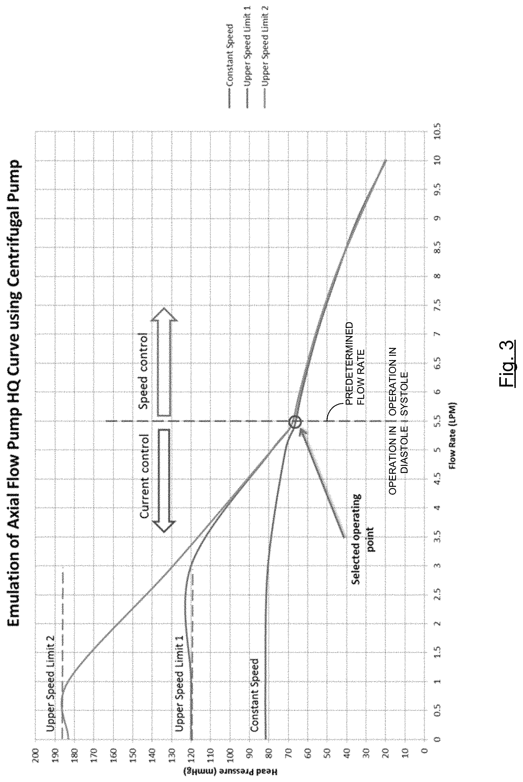
FIG. 3 is a graph showing the head pressure flow curve characteristics (head pressure versus flow) of a centrifugal pump controlled in a manner of one embodiment of the invention;
FIG. 4 is a block diagram of one embodiment of the invention for controlling a centrifugal pump to produce the head pressure flow curve shown in FIG. 3;
FIG. 5 is a graph showing torque current (IQ) over the cardiac cycle of a patient having a ventricular assist device with a centrifugal pump being operated in two different manners, one according to embodiments of the present invention; and
FIG. 6 is a block diagram of an exemplary computer system capable of being used in at least some portion of the apparatuses or systems of the present invention, or implementing at least some portion of the methods of the present invention.
In the appended figures, similar components and/or features may have the same numerical reference label. Further, various components of the same type may be distinguished by following the reference label by a letter that distinguishes among the similar components and/or features. If only the first numerical reference label is used in the specification, the description is applicable to any one of the similar components and/or features having the same first numerical reference label irrespective of the letter suffix.
DETAILED DESCRIPTION OF THE INVENTION
The ensuing description provides exemplary embodiments only, and is not intended to limit the scope, applicability or configuration of the disclosure. Rather, the ensuing description of the exemplary embodiments will provide those skilled in the art with an enabling description for implementing one or more exemplary embodiments. It being understood that various changes may be made in the function and arrangement of elements without departing from the spirit and scope of the invention as set forth in the appended claims.
For example, any detail discussed with regard to one embodiment may or may not be present in all contemplated versions of that embodiment. Likewise, any detail discussed with regard to one embodiment may or may not be present in all contemplated versions of other embodiments discussed herein. Finally, the absence of discussion of any detail with regard to embodiment herein shall be an implicit recognition that such detail may or may not be present in any version of any embodiment discussed herein.
Specific details are given in the following description to provide a thorough understanding of the embodiments. However, it will be understood by one of ordinary skill in the art that the embodiments may be practiced without these specific details. For example, circuits, systems, networks, processes, and other elements in the invention may be shown as components in block diagram form in order not to obscure the embodiments in unnecessary detail. In other instances, well-known circuits, processes, algorithms, structures, and techniques may be shown without unnecessary detail in order to avoid obscuring the embodiments.
Also, it is noted that individual embodiments may be described as a process which is depicted as a flowchart, a flow diagram, a data flow diagram, a structure diagram, or a block diagram. Although a flowchart may describe the operations as a sequential process, many of the operations can be performed in parallel or concurrently. In addition, the order of the operations may be re-arranged. A process may be terminated when its operations are completed, but could have additional steps not discussed or included in a figure. Furthermore, not all operations in any particularly described process may occur in all embodiments. A process may correspond to a method, a function, a procedure, a subroutine, a subprogram, etc. When a process corresponds to a function, its termination corresponds to a return of the function to the calling function or the main function.
The term "machine-readable medium" includes, but is not limited to transitory and non-transitory, portable or fixed storage devices, optical storage devices, wireless channels and various other mediums capable of storing, containing or carrying instruction(s) and/or data. A code segment or machine-executable instructions may represent a procedure, a function, a subprogram, a program, a routine, a subroutine, a module, a software package, a class, or any combination of instructions, data structures, or program statements. A code segment may be coupled to another code segment or a hardware circuit by passing and/or receiving information, data, arguments, parameters, or memory contents. Information, arguments, parameters, data, etc. may be passed, forwarded, or transmitted via any suitable means including memory sharing, message passing, token passing, network transmission, etc.
Furthermore, embodiments of the invention may be implemented, at least in part, either manually or automatically. Manual or automatic implementations may be executed, or at least assisted, through the use of machines, hardware, software, firmware, middleware, microcode, hardware description languages, or any combination thereof. When implemented in software, firmware, middleware or microcode, the program code or code segments to perform the necessary tasks may be stored in a machine readable medium. A processor(s) may perform the necessary tasks.
For convenience in explanation and accurate definition in the appended claims, the terms "up" or "upper," "down" or "lower," "inside" and "outside" are used to describe features of the present invention with reference to the positions of such features as displayed in the figures.
With reference to FIG. 2 the placement of an exemplary pump 205 in the cardiovascular system will now be described. In various embodiments, the design concept 200 includes pump 205 connected to the left ventricle 210 of a heart 225. Blood is typically drawn into left ventricle 210 from left atrium 250 and expelled to the ascending aorta through aortic valve 220. In the exemplary system, blood from left ventricle 210 is drawn into an inflow of pump 205 and driven through an outflow graft to aorta 265. In the exemplary embodiment, pump 205 is implanted at or near the apex 255 of left ventricle 210. The flow through exemplary pump 205 is estimated using pump parameters which include power/current, speed (RPM) and a flow map, which allows transformation of inputs like power/current and speed to flow based on the pump flow characteristics curves (e.g. HQ head pressure-flow curves). Heart 225 includes pulmonary valve 230, tricuspid valve 235, mitral valve 240, right atrium 245, and left atrium 250. Pulmonary artery 260, aorta 265, vena cavae 270, and pulmonary vein 275 are also shown in FIG. 2. Blocks representing pulmonary circulation 280 and systemic circulation 285 are also shown. A controller 290 may execute operation of pump 205 as will be understood by one of skill in the art from the description herein.
In embodiments of the present invention, pump speed may be controlled such that it operates at a first speed above a predetermined flow rate of blood through the pump, and at a second speed below the predetermined flow rate through the pump. A clinician may set the predetermined flow rate to correspond with a flowrate indicative of a crossover point between the patient's systolic and diastolic cardiac phases. In this manner, the pressure generated by the pump may be increased during the diastolic phase, when pressure generated by the patient's heart on its own is at its lowest. The first speed may represent a minimum operating speed for the pump.
FIG. 3 shows an HQ curve (head pressure versus flow) of a centrifugal pump operated in accordance with such embodiments of the invention using the exemplary system shown in FIG. 4. While the centrifugal pump is operated at a first speed in high flow situations (e.g., in systole), the pump is operated at a higher, second speed, in low flow situations (e.g., in diastole), and thereby simulates the properties of an axial flow pump in low flow situations (e.g., in diastole). Thus, as shown in FIG. 5, by operating a centrifugal pump in this manner, pressure generated may be increased during diastole when compared to operating the centrifugal pump in a conventional manner at a constant set speed across both systole and diastole.
Thus, in one embodiment a method may be provided for controlling a centrifugal pump in a ventricular assist or other device. This method may be conducted by pump controller 290. Pump controller 290 may include a processor and a non-transitory readable medium as discussed further herein.
The method may include causing the centrifugal pump to operate at a first speed above a predetermined flow rate, and causing the centrifugal pump to operate at a second speed below the predetermined flow rate. The first speed may be a minimum set operating speed of the centrifugal pump. The second speed may be greater than the first speed.
When the centrifugal pump is operating at the first speed, a motor of the centrifugal pump may be operating at a variable current but at a constant speed, where the constant speed may be a speed within a certain RPM range, or within 5%, 10%, or other range of the clinician set speed. When the centrifugal pump is operating at the second speed, the motor of the centrifugal pump may be operating at a constant current and/or voltage, so as to maintain a constant back electromotive force (emf), left ventricular pressure, pulmonic pressure, and/or aortic pressure.
To determine when to switch between the first speed and the second speed, the method may include determining an estimated flow rate through the pump based at least in part on a measured current of a motor of the centrifugal pump. The estimated flow rate may then be compared to the predetermined flow rate set by the clinician. In other embodiments, an actual flow rate may be determined with a flow measurement sensor, and then compared to the predetermined flow rate. In some embodiments, the method may also include detecting or identifying a suction event in the centrifugal pump and reducing a speed of the centrifugal pump to alleviate the suction event.
Additional related publications discuss ventricular assist device control schemes and devices which may be applicable to some or all of the disclosed embodiments herein. These publications include U.S. Patent Application Publication Nos. 2014/0323796, 2016/0058930, 2016/0058929, and 2016/0228628 and U.S. Pat. Nos. 7,862,501, 8,096,935, 8,870,552, and 9,039,595. The disclosure of each of the aforementioned patent application publications and patents are hereby incorporated by reference, for all purposes, as if fully set forth herein.
FIG. 6 is a block diagram illustrating an exemplary computer system 600 in which embodiments of the present invention may be implemented. This example illustrates a computer system 600 such as may be used, in whole, in part, or with various modifications, to provide the functions of pump controller 290 and/or other components of the invention such as those discussed above. For example, various functions of pump controller 290 may be controlled by the computer system 600, including, merely by way of example, determining a flow rate through pump 205, causing pump 205 to operate at a constant speed, causing pump 205 to operate at a variable speed, etc.
The computer system 600 is shown comprising hardware elements that may be electrically coupled via a bus 690. The hardware elements may include one or more central processing units 610, one or more input devices 620 (e.g., a mouse, a keyboard, etc.), and one or more output devices 630 (e.g., a display device, a printer, etc.). The computer system 600 may also include one or more storage device 640. By way of example, storage device(s) 640 may be disk drives, optical storage devices, solid-state storage device such as a random access memory ("RAM") and/or a read-only memory ("ROM"), which can be programmable, flash-updateable and/or the like.
The computer system 600 may additionally include a computer-readable storage media reader 650, a communications system 660 (e.g., a modem, a network card (wireless or wired), an infra-red communication device, Bluetooth.TM. device, cellular communication device, etc.), and working memory 680, which may include RAM and ROM devices as described above. In some embodiments, the computer system 600 may also include a processing acceleration unit 670, which can include a digital signal processor, a special-purpose processor and/or the like.
The computer-readable storage media reader 650 can further be connected to a computer-readable storage medium, together (and, optionally, in combination with storage device(s) 640) comprehensively representing remote, local, fixed, and/or removable storage devices plus storage media for temporarily and/or more permanently containing computer-readable information. The communications system 660 may permit data to be exchanged with a network, system, computer and/or other component described above.
The computer system 600 may also comprise software elements, shown as being currently located within a working memory 680, including an operating system 684 and/or other code 688. It should be appreciated that alternate embodiments of a computer system 600 may have numerous variations from that described above. For example, customized hardware might also be used and/or particular elements might be implemented in hardware, software (including portable software, such as applets), or both. Furthermore, connection to other computing devices such as network input/output and data acquisition devices may also occur.
Software of computer system 600 may include code 688 for implementing any or all of the function of the various elements of the architecture as described herein. For example, software, stored on and/or executed by a computer system such as system 600, can provide the functions of pump controller 290, and/or other components of the invention such as those discussed above. Methods implementable by software on some of these components have been discussed above in more detail. In other embodiments, the methods described herein may be implemented in hardware besides a microprocessor. For example, the methods described herein may be conducted on an application-specific integrated circuit (ASIC) or a field-programmable gate array (FPGA).
The systems and methods described herein provide several advantages over existing approaches. By combining properties of a centrifugal pump in a high flow region (i.e. in systole) and properties of an axial flow pump in a low flow region (i.e. in diastole) the system potentially improves hemodynamics and increases assistance for the failing heart. The present inventions may also improve ventricular unloading and/or the capacity to support patients during exercise and other high capacity periods.
The invention has now been described in detail for the purposes of clarity and understanding. However, it will be appreciated that certain changes and modifications may be practiced within the scope of this disclosure and the appended claims.
* * * * *
References
D00000
D00001
D00002
D00003
D00004
D00005
D00006
XML
uspto.report is an independent third-party trademark research tool that is not affiliated, endorsed, or sponsored by the United States Patent and Trademark Office (USPTO) or any other governmental organization. The information provided by uspto.report is based on publicly available data at the time of writing and is intended for informational purposes only.
While we strive to provide accurate and up-to-date information, we do not guarantee the accuracy, completeness, reliability, or suitability of the information displayed on this site. The use of this site is at your own risk. Any reliance you place on such information is therefore strictly at your own risk.
All official trademark data, including owner information, should be verified by visiting the official USPTO website at www.uspto.gov. This site is not intended to replace professional legal advice and should not be used as a substitute for consulting with a legal professional who is knowledgeable about trademark law.