User pairing method, wireless station and wireless system
Su , et al. December 29, 2
U.S. patent number 10,880,931 [Application Number 16/519,022] was granted by the patent office on 2020-12-29 for user pairing method, wireless station and wireless system. This patent grant is currently assigned to Realtek Semiconductor Corp.. The grantee listed for this patent is Realtek Semiconductor Corp.. Invention is credited to Yao-Yuan Chang, Der-Zheng Liu, Hsuan-Jung Su.


View All Diagrams
| United States Patent | 10,880,931 |
| Su , et al. | December 29, 2020 |
User pairing method, wireless station and wireless system
Abstract
A user pairing method is provided. The method includes the following steps: selecting a first uplink user device among the uplink set; selecting a first downlink user device among the downlink set; determining whether the first uplink channel gain corresponding to the first uplink user device is greater than a second uplink channel gain corresponding to the first downlink user device, to generate a first determination result; determining whether a first signal to noise plus interference ratio (SINR) perceived at the first downlink user device is greater than a first SINR threshold, to generate a second determination result; forming the first uplink user device and the first downlink user device as a first user pair in a full duplexing (FD) mode when the first determination result and the second first determination result are positive.
| Inventors: | Su; Hsuan-Jung (Taipei, TW), Chang; Yao-Yuan (Tainan, TW), Liu; Der-Zheng (Hsinchu County, TW) | ||||||||||
|---|---|---|---|---|---|---|---|---|---|---|---|
| Applicant: |
|
||||||||||
| Assignee: | Realtek Semiconductor Corp.
(HsinChu, TW) |
||||||||||
| Family ID: | 1000005272570 | ||||||||||
| Appl. No.: | 16/519,022 | ||||||||||
| Filed: | July 23, 2019 |
Prior Publication Data
| Document Identifier | Publication Date | |
|---|---|---|
| US 20200120722 A1 | Apr 16, 2020 | |
Related U.S. Patent Documents
| Application Number | Filing Date | Patent Number | Issue Date | ||
|---|---|---|---|---|---|
| 62744664 | Oct 12, 2018 | ||||
| Current U.S. Class: | 1/1 |
| Current CPC Class: | H04L 5/1438 (20130101); H04L 5/14 (20130101); H04W 76/10 (20180201); H04L 67/38 (20130101); H04L 5/143 (20130101); H04W 72/082 (20130101) |
| Current International Class: | H04W 76/10 (20180101); H04L 5/14 (20060101); H04W 72/08 (20090101); H04L 29/06 (20060101) |
| Field of Search: | ;370/277,329 |
References Cited [Referenced By]
U.S. Patent Documents
| 8547884 | October 2013 | Lo |
| 9363066 | June 2016 | Lo |
| 9420606 | August 2016 | Bhushan |
| 9698963 | July 2017 | Luo |
| 9839037 | December 2017 | Lo |
| 10212723 | February 2019 | Jiang |
| 10298297 | May 2019 | Cui |
| 10368357 | July 2019 | Lopez-Perez |
| 10567147 | February 2020 | DiFazio |
| 2018/0213547 | July 2018 | Ju |
| 2019/0123855 | April 2019 | Stirling-Gallacher |
| 2020/0119900 | April 2020 | Lai |
Other References
|
Deli Liu et al., The Sub-channel Allocation Algorithm in Femtocell Networks Based on Ant Colony Optimization, 2013 IEEE, MILCOM 2012--2012 IEEE Military Communications Conference, 2012. cited by applicant . Kwang Mong Sim et al., Ant Colony Optimization for Routing and Load-Balancing: Survey and New Directions, IEEE 2003, IEEE Transactions on Systems, Man, and Cybernetics--Part A: Systems and Humans, vol. 33, No. 5, Sep. 2003, pp. 560-572. cited by applicant. |
Primary Examiner: Phan; Man U
Attorney, Agent or Firm: Hsu; Winston
Parent Case Text
CROSS REFERENCE TO RELATED APPLICATIONS
This application claims the benefit of U.S. provisional application No. 62/744,664, filed on Oct. 12, 2018, which is incorporated herein by reference.
Claims
What is claimed is:
1. A user pairing method, applied in a wireless station, the method comprising: (a) the wireless station obtaining an uplink set and a downlink set; (b) the wireless station selecting a first uplink user device among the uplink set, wherein a first uplink channel gain corresponding to the first uplink user device is the strongest uplink channel gain among uplink channel gains corresponding to uplink user devices within the uplink set; (c) the wireless station selecting a first downlink user device among the downlink set, wherein a first downlink channel gain corresponding to the first downlink user device is the strongest downlink channel gain among downlink channel gains corresponding to downlink user devices within the downlink set; (d) the wireless station determining whether the first uplink channel gain corresponding to the first uplink user device is greater than a second uplink channel gain corresponding to the first downlink user device, to generate a first determination result; (e) the wireless station determining whether a first signal to noise plus interference ratio (SINR) perceived at the first downlink user device is greater than a first SINR threshold, to generate a second determination result; and (f) the wireless station forming the first uplink user device and the first downlink user device as a first user pair in a full duplexing (FD) mode when the first determination result and the second first determination result are positive, wherein the first user pair in the FD mode represents that an uplink transmission by the first uplink user device and a downlink transmission by the first downlink user device are performed within a time period and a frequency spectrum.
2. The method of claim 1, further comprising: (g) the wireless station determining whether a mutual channel gain between the first uplink user device and the first downlink device is less than or equal to a specific value, to generate a third determination result; and (h) the wireless station forming the first uplink user device and the first downlink user device as the first user pair in the FD mode, when the first determination result is negative, and when the second determination result and the third determination result are positive.
3. The method of claim 1, further comprising: the wireless station removing the first uplink user device from the uplink set to update the uplink set and the wireless station removing the first downlink user device from the downlink set to update the downlink set, when the first uplink user device and the first downlink user device are formed as the first user pair in the FD mode.
4. The method of claim 2, further comprising: the wireless station removing the first downlink user device from the downlink set to update the downlink set, when the first uplink user device and the first downlink user device are not formed as the first user pair in the FD mode.
5. The method of claim 4, further comprising: after the wireless station removing the first downlink user device from the downlink set, the wireless station performing the steps (c)-(h) until there is one downlink device within the downlink set which can be paired with the first uplink user device, or until there is no other downlink device within the downlink set which can be paired with the first uplink user device.
6. The method of claim 5, further comprising: the wireless station removing the first uplink user device from the uplink set to update the uplink set if there is no other downlink device within the downlink set which can be paired with the first uplink user device.
7. The method of claim 2, further comprising: the wireless station removing the first uplink user device from the uplink set to update the uplink set and the wireless station removing the first downlink user device from the downlink set to update the downlink set, when the first uplink user device and the first downlink user device are formed as the first user pair in the FD mode, or the wireless station removing the first downlink user device from the downlink set to update the downlink set, when the first uplink user device and the first downlink user device are not formed as the first user pair in the FD mode.
8. The method of claim 7, further comprising: after the wireless station removing the first uplink user device from the uplink and the wireless station removing the first downlink user device from the downlink set, the wireless station performing the steps (b)-(h) based on the updated uplink set and the updated downlink set.
9. A wireless station, comprising: a storage device, storing a program code; and a processing unit, wherein the program code instructs the processing unit to perform the following steps: (a) obtaining an uplink set and a downlink set; (b) selecting a first uplink user device among the uplink set, wherein a first uplink channel gain corresponding to the first uplink user device is the strongest uplink channel gain among uplink channel gains corresponding to uplink user devices within the uplink set; (c) selecting a first downlink user device among the downlink set, wherein a first downlink channel gain corresponding to the first downlink user device is the strongest downlink channel gain among downlink channel gains corresponding to downlink user devices within the downlink set; (d) determining whether the first uplink channel gain corresponding to the first uplink user device is greater than a second uplink channel gain corresponding to the first downlink user device, to generate a first determination result; (e) determining whether a first signal to noise plus interference ratio (SINR) perceived at the first downlink user device is greater than a first SINR threshold, to generate a second determination result; and (f) forming the first uplink user device and the first downlink user device as a first user pair in a full duplexing (FD) mode when the first determination result and the second first determination result are positive, wherein the first user pair in the FD mode represents that an uplink transmission by the first uplink user device and a downlink transmission by the first downlink user device are performed within a time period and a frequency spectrum.
10. The wireless station of claim 9, wherein the program code further instructs the processing unit to perform the following steps: (g) determining whether a mutual channel gain between the first uplink user device and the first downlink device is less than or equal to a specific value, to generate a third determination result; and (h) forming the first uplink user device and the first downlink user device as the first user pair in the FD mode, when the first determination result is negative, and when the second determination result and the third determination result are positive.
11. The wireless station of claim 9, wherein the program code further instructs the processing unit to perform the following steps: removing the first uplink user device from the uplink set to update the uplink set and removing the first downlink user device from the downlink set to update the downlink set, when the first uplink user device and the first downlink user device are formed as the first user pair in the FD mode.
12. The wireless station of claim 10, wherein the program code further instructs the processing unit to perform the following step: removing the first downlink user device from the downlink set to update the downlink set, when the first uplink user device and the first downlink user device are not formed as the first user pair in the FD mode.
13. The wireless station of claim 12, wherein the program code further instructs the processing unit to perform the following steps: after removing the first downlink user device from the downlink set, performing the steps (c)-(h) until there is one downlink device within the downlink set which can be paired with the first uplink user device, or until there is no other downlink device within the downlink set which can be paired with the first uplink user device.
14. The wireless station of claim 13, wherein the program code further instructs the processing unit to perform the following steps: removing the first uplink user device from the uplink set to update the uplink set if there is no other downlink device within the downlink set which can be paired with the first uplink user device.
15. The wireless station of claim 10, wherein the program code further instructs the processing unit to perform the following steps: removing the first uplink user device from the uplink set to update the uplink set and removing the first downlink user device from the downlink set to update the downlink set, when the first uplink user device and the first downlink user device are formed as the first user pair in the FD mode, or removing the first downlink user device from the downlink set to update the downlink set, when the first uplink user device and the first downlink user device are not formed as the first user pair in the FD mode.
16. The method of claim 15, wherein the program code further instructs the processing unit to perform the following steps: after removing the first uplink user device from the uplink and removing the first downlink user device from the downlink set, performing the steps (b)-(h) based on the updated uplink set and the updated downlink set.
17. A wireless system, comprising: a plurality of uplink user devices and a plurality of downlink user devices; and a wireless station, comprising: a storage device, storing a program code; and a processing unit, wherein the program code instructs the processing unit to perform the following steps: (a) obtaining an uplink set and a downlink set; (b) selecting a first uplink user device among the uplink set, wherein a first uplink channel gain corresponding to the first uplink user device is the strongest uplink channel gain among uplink channel gains corresponding to the uplink user devices within the uplink set; (c) selecting a first downlink user device among the downlink set, wherein a first downlink channel gain corresponding to the first downlink user device is the strongest downlink channel gain among downlink channel gains corresponding to downlink user devices within the downlink set; (d) determining whether the first uplink channel gain corresponding to the first uplink user device is greater than a second uplink channel gain corresponding to the first downlink user device, to generate a first determination result; (e) determining whether a first signal to noise plus interference ratio (SINR) perceived at the first downlink user device is greater than a first SINR threshold, to generate a second determination result; and (f) forming the first uplink user device and the first downlink user device as a first user pair in a full duplexing (FD) mode when the first determination result and the second first determination result are positive, wherein the first user pair in the FD mode represents that an uplink transmission by the first uplink user device and a downlink transmission by the first downlink user device are performed within a time period and a frequency spectrum.
18. The wireless system of claim 17, wherein the program code further instructs the processing unit to perform the following steps: (g) determining whether a mutual channel gain between the first uplink user device and the first downlink device is less than or equal to a specific value, to generate a third determination result; and (h) forming the first uplink user device and the first downlink user device as the first user pair in the FD mode, when the first determination result is negative and the second determination result and the third determination result are positive.
19. The wireless system of claim 17, wherein the program code further instructs the processing unit to perform the following step: removing the first uplink user device from the uplink set to update the uplink set and removing the first downlink user device from the downlink set to update the downlink set, when the first uplink user device and the first downlink user device are formed as the user pair in the FD mode.
20. The wireless system of claim 17, wherein the program code further instructs the processing unit to perform the following step: removing the first downlink user device from the downlink set to update the downlink set, when the first uplink user device and the first downlink user device are not formed as the user pair in the FD mode.
Description
BACKGROUND OF THE INVENTION
1. Field of the Invention
The present disclosure relates to a user pairing method, a wireless station and a wireless system, and more particularly, to a user pairing method, a wireless station and a wireless system capable of maximizing sum rate.
2. Description of the Prior Art
As the demand of wireless service increases, the utilized frequency spectrum is getting crowded, which might degrade the quality of service (QoS) of wireless system. Enhancing data rate is always a goal for the next generation mobile communication. Full-duplexing (FD) communications, allowing simultaneous transmission and reception on the same frequency carrier(s), attract more attentions recently, which is expected to be a promising way to increase spectrum efficiency.
Previously, strong self-interference makes FD communications difficult to be realized. Thanks to the breakthroughs in hardware development, self interference is able to be reduced by 110 dB, which makes FD communications possible to be realized and able to upgrade the capacity to anew level. In FD systems, user pairing is necessary.
SUMMARY OF THE INVENTION
It is a primary objective of the present disclosure to provide a user pairing method, a wireless station and a wireless system capable of maximizing sum rate.
An embodiment of the present disclosure provides a user pairing method, applied in a wireless station. The method comprises the steps of (a) obtaining an uplink set and a downlink set; (b) selecting a first uplink user device among the uplink set, wherein a first uplink channel gain corresponding to the first uplink user device is the strongest uplink channel gain among uplink channel gains corresponding to uplink user devices within the uplink set; (c) selecting a first downlink user device among the downlink set, wherein a first downlink channel gain corresponding to the first downlink user device is the strongest downlink channel gain among downlink channel gains corresponding to downlink user devices within the downlink set; (d) determining whether the first uplink channel gain corresponding to the first uplink user device is greater than a second uplink channel gain corresponding to the first downlink user device, to generate a first determination result; (e) determining whether a first signal to noise plus interference ratio (SINR) perceived at the first downlink user device is greater than a first SINR threshold, to generate a second determination result; (f) forming the first uplink user device and the first downlink user device as a first user pair in a full duplexing (FD) mode when the first determination result and the second determination result are positive, wherein the first user pair in the FD mode represents that an uplink transmission by the first uplink user device and a downlink transmission by the first downlink user device are performed within a time period and a frequency spectrum.
An embodiment of the present disclosure further provides a wireless station, configured to execute the user pairing method stated above.
An embodiment of the present disclosure further provides a wireless system. The wireless system includes multiple uplink user devices, multiple downlink user devices and the wireless station stated above.
BRIEF DESCRIPTION OF THE DRAWINGS
FIG. 1 is a schematic diagram of a wireless system according to an embodiment of the present disclosure.
FIG. 2 is a schematic diagram of a wireless station according to an embodiment of the present disclosure.
FIG. 3 is a schematic diagram of a method according to an embodiment of the present disclosure.
DETAILED DESCRIPTION
FIG. 1 is a schematic diagram of a wireless system 10 according to an embodiment of the present disclosure. The wireless system 10 may be a centralized-control system, e.g., a cellular system, or even be a distributed-control system, e.g., a system forming an ad hoc network. The wireless system 10 comprises a wireless station BS and a plurality of user devices UE. The wireless station BS may be regarded as a base station, in any scale, e.g., a macro base station or a femtocell base station. The user device UE may be a user's equipment, in LTE terminology, which can be a cell phone which FIG. 1 illustrated, or otherwise be a tablet computer, a laptop or the like. Some of the user devices UE are uplink (UL) user devices while some are downlink (DL) user devices.
The wireless system 10 or the wireless station BS may operate in a full duplexing (FD) mode with some of the user devices UE, and operate in a half duplexing (HD) mode with some of the user devices UE. For exemplary purpose, some user devices UE in FIG. 1 are further annotated as UE.sub.UL,FD, UE.sub.DL,FD, UE.sub.UL,HD, UE.sub.DL,HD. In this case, the wireless station BS may operate in the FD mode with the user devices UE.sub.UL,FD, UE.sub.DL,FD, and operate in the HD mode with the user devices UE.sub.UL,HD, UE.sub.DL,HD.
In the FD mode, the wireless station BS receives data from the uplink user device UE.sub.UL,FD, and transmits data to the downlink user device UE.sub.DL,FD, at the same period of time and at the same frequency spectrum (e.g., one or more OFDM subcarrier(s)), as the right-bottom corner of FIG. 1 illustrates. In the HD mode, the wireless station BS receives data from the uplink user device UE.sub.UL,HD and transmits data to the downlink user device UE.sub.DL,HD at the same frequency spectrum but in different time periods, as the right-bottom corner of FIG. 1 illustrates. It is assumed that configuration in FIG. 1 is under time division duplexing (TDD) scheme, but the invention is not limited thereto. In an embodiment, frequency division duplexing (FDD) or other division duplexing scheme can be utilized by the wireless station BS, which is also within the scope of the present disclosure.
The user devices UE.sub.UL,FD, UE.sub.DL,FD are formed as an user pair. The wireless station BS is configured to form the user pair(s) (i.e., perform a user pairing operation) among the plurality of user devices UE, and operates in the FD mode with the user pair(s), or with the paired uplink user device(s) and the paired downlink user device(s) in the FD mode. The wireless station BS may operate in the HD mode with the rest of the user device(s).
Furthermore, the wireless station BS may perform the user pairing operation according to the channel gains between the user devices UE and the wireless station BS. The channel gain is actually the channel attenuation, the attenuation of a specific channel between the wireless station BS and a specific user device UE. If the wireless system 10 is latency tolerable, the channel gain can be obtained from indicators such as RSSI, RSRP, RSRQ and/or the like, fed back from the user devices UE. If the wireless system 10 is an ultra-low latency system, in which handshaking protocols exchanging channel information are not allowed, the channel gains between the user devices UE and the wireless station BS can be approximated by the distances between the user devices UE and the wireless station BS, given that the distance information (between the UEs and the BS) is available at the wireless station BS. In an embodiment, the distance information (between UEs and BS) may be obtained via some positioning technologies, which is not narrated herein.
FIG. 2 is a schematic diagram of the wireless station BS according to an embodiment of the present disclosure. In addition to antennas, the wireless station BS comprises a storage device 20 and a processing unit 22. The storage device 20 is configured to store a program code 200, and the program code 200 is configured to instruct the processing unit 22 to perform a user pairing operation. The storage device 20 may be, for example, a random access memory (RAM), a read-only memory (ROM), a volatile memory, or a non-volatile memory (NVM), e.g., an electrically erasable programmable read only memory (EEPROM) or a flash memory, which is not limited thereto. The processing unit 22 may be, for example, an application specific integrated circuit (ASIC), a central processing unit (CPU), a digital signal processor (DSP), or a tensor processing unit (TPU), which is not limited thereto.
The processing unit 22 may perform the user pairing operation to maximize an overall sum rate of the wireless system 10, subject to some transmission power constraints and reliable constraints (e.g., an SINR (signal to noise plus interference ratio) constraint in general). In an embodiment, the user pairing operation can be regarded to solve an optimization problem as
.times..times..times..function..times..times..function..times..times..tim- es..times..ltoreq..A-inverted..times..times..times..ltoreq..A-inverted..ti- mes..times..times..ltoreq..A-inverted..times..times..times..ltoreq..times.- .times..ltoreq..times..A-inverted..times..times..gtoreq..A-inverted..times- . ##EQU00001##
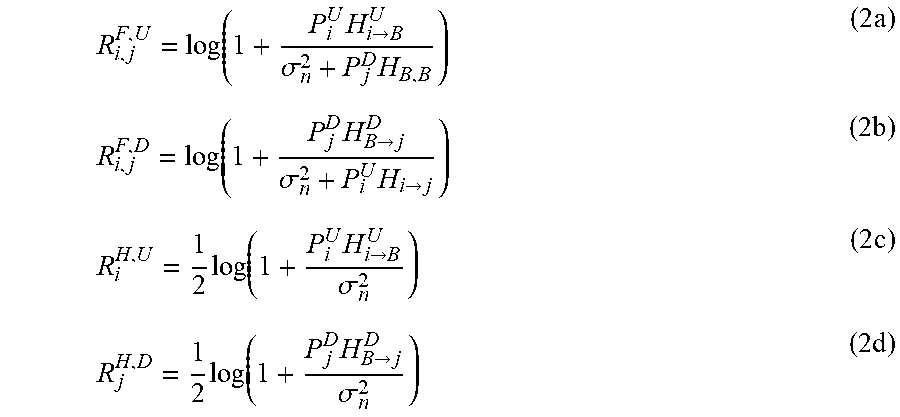
In equations (1a)-(1g), i/j is an uplink/downlink user device index, x.sub.i,j/y.sub.i,j is an indicator, being either 0 or 1, to indicate where the user devices UE.sub.UL,i, and UE.sub.DL,j are paired in the FD/HD mode. In an embodiment, K.sub.UL=K.sub.DL=K. R.sub.i,j.sup.F,U, R.sub.i,j.sup.F,D, R.sub.i.sup.H,U, R.sub.j.sup.H,D can be expressed as
.function..times.>.sigma..times..times..function..times.>.sigma..ti- mes.>.times..times..times.>.sigma..times..times..times.>.sigma..t- imes. ##EQU00002##
In equations (2a)-(2d), R.sub.i,j.sup.F,U represents an uplink rate contributed by the uplink user device UE.sub.UL,i in the FD mode given UE.sub.DL,j is the FD paired downlink user device, R.sub.i,j.sup.F,D represents a downlink rate for the downlink user device UE.sub.DL,j in the FD mode given UE.sub.UL,i is the FD paired uplink user device, R.sub.i.sup.H,U represents an uplink rate contributed by the uplink user device UE.sub.UL,i in the HD mode, and R.sub.j.sup.H,D represents a downlink rate for the downlink user device UE.sub.DL,j in the HD mode. In some embodiments, the uplink rate and the downlink rate can be viewed as an average uplink rate and an average downlink rate respectively.
P.sub.i.sup.U is an uplink transmission power of the uplink user device UE.sub.UL,i, and P.sub.j.sup.D is a downlink transmission power for the downlink user device UE.sub.DL,j. H.sub.i.fwdarw.B.sup.U is an uplink channel gain from the uplink user device UE.sub.UL,i to the station BS, and H.sub.B.fwdarw.j.sup.D is a downlink channel gain from the station BS to the downlink user device UE.sub.DL,j. P.sub.j.sup.DH.sub.B,B represents a residual self-interference, perceived at the wireless station BS. H.sub.i.fwdarw.j represents a mutual channel gain from UE.sub.UL,i to UE.sub.DL,j. .sigma..sub.n.sup.2 represents a noise power.
Equation (1a) represents the objective is to maximize the sum rate. Equation (1b) represents that only one downlink user device UE.sub.DL,j can be paired with one uplink user device UE.sub.UL,i in the FD mode. Equation (1c) represents that only one downlink user device UE.sub.DL,j can be paired with one uplink user device UE.sub.UL,i in the HD mode. Equation (1d) represents that the user pair (UE.sub.UL,i, UE.sub.DL,j) cannot operate in both the FD mode and the HD mode. Equations (1e) and (1f) are transmission power constraints for the station BS and the user device UE. Equation (1g) symbolically represents the reliable constraints to make sure that the data received can be successfully decodable, which may symbolically represent one or more SINR constraints, where SINR.sub.i,j may be one of, a part of, or all of the second terms within the logarithm function of eq. (2a)-(2d).
The user pairing operation may be based on three properties as discussed in the following.
First, given the user devices UE.sub.a and UE.sub.b are paired in the FD operation mode, choosing the user device with larger channel gain (choosing among UE.sub.a and UE.sub.b) as the uplink user device would bring more performance in terms of transmission rate. By comparing a first sum rate of "UE.sub.a being the uplink user device and UE.sub.b being the downlink user device" with a second sum rate of "UE.sub.b being the uplink user device and UE.sub.a being the downlink user device", a situation can be expressed as equation (3a). Under a condition of P.sub.a.sup.U=P.sub.a.sup.D=P.sub.b.sup.U=P.sub.b.sup.D, it is found that equation (3a) would be equivalent to (3b). That is, if the inequality (3b) is true/sustained, then the inequality (3a) would be true/sustained. R.sub.a,b.sup.F,U+R.sub.a,b.sup.F,D>R.sub.b,a.sup.F,U+R.sub.b,a.sup.F,- D (3a) H.sub.a.fwdarw.B.sup.U-H.sub.b.fwdarw.B.sup.U>0 (3b)
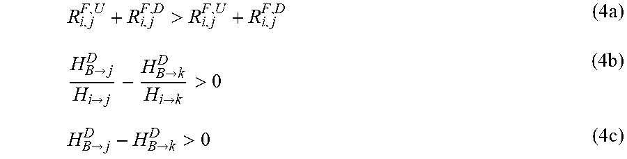
Second, given that the user device UE.sub.UL,i is a candidate uplink user device in the FD mode, choosing the downlink user device with larger channel gain (choosing among all downlink user devices UE.sub.DL,1-UE.sub.DL,K', where K'=K.sub.DL) to pair with UE.sub.UL,i would bring more performance in terms of transmission rate. By comparing a third sum rate of a user pair (UE.sub.UL,i, UE.sub.DL,j) with a fourth sum rate of another user pair (UE.sub.UL,i, UE.sub.DL,k.noteq.j), a situation can be expressed as equation (4a). Under the condition of P.sub.a.sup.u=P.sub.a.sup.D=P.sub.b.sup.U=P.sub.b.sup.D, it is found that equation (4a) would be equivalent to equation (4b), and a condition expressed in equation (4c) is with high probability to make equation (4b) sustained. That is, if inequality (4c) is true/sustained, then the inequality (4a) would likely be true/sustained.
>.times.>>>>>.times.>>>.times. ##EQU00003##
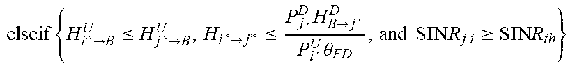
Third, given that (UE.sub.UL,i, UE.sub.DL,j) has been paired, if the mutual channel gain H.sub.i.fwdarw.j is too large, operating in the HD mode would bring more performance in terms of transmission rate. By comparing a fifth sum rate of the HD mode with a sixth sum rate of the FD mode, a situation can be expressed as equation (5a). Assuming R.sub.i,j.sup.F,D is negligible when an SINR, denoted as SINR.sub.i,j, is less than a threshold .theta..sub.FD, as equation (5b) expresses. Equation (5b) is true/sustained when equation (5c) is true/sustained. When equation (5c) is true/sustained, meaning that the mutual channel gain H.sub.i.fwdarw.j is too large, equation (5a) can be reformulated as equation (5d), and a necessary condition expressed as equation (5e) is found. Unless equation (5c) is false, the user pair (UE.sub.UL,i, UE.sub.DL,j) would operate in the HD mode.
>.times..times.>.sigma..times.><.theta..times.>>.times.- >.times..theta..times.>.times.>.gtoreq.>.times. ##EQU00004##
Based on the three properties in the above, the user pairing operation may be listed in Table I, and may be compiled as the program code 200.
TABLE-US-00001 TABLE I 1 Initialization 2 Obtain an uplink index set US = {1, . . . , K.sub.uL} and UL channel gains H.sub.i .fwdarw. B.sup.U, .A-inverted.i .di-elect cons. US 3 Obtain a downlink index set DS = {1, . . . , K.sub.DL} and DL channel gains H.sub.B .fwdarw. j.sup.D, .A-inverted.j.di-elect cons. DS 4 Set x.sub.i,j = 0, .A-inverted.i.di-elect cons. US and j.di-elect cons. DS 5 Set FUS = FDS = HUS = HDS = .PHI. 6 repeat 7 .times..times..times..times..times..times..times..times..times..times..- times..times..times..times..times..times..times..times..di-elect cons..times..times..fwdarw. ##EQU00005## 8 repeat 9 .times..times..times..times..times..times..times..times..times..times- ..times..times..times..times..times..times..times..times..times..di-elect cons..times..times..fwdarw. ##EQU00006## 10 if {H.sub.i*.fwdarw.B.sup.U >H.sub.j*.fwdarw.B.sup.U and SINR.sub.j|i .gtoreq. SINR.sub.th} 11 then 12 x.sub.i*,j* = 1; 13 US US \ {i*}, FUS {i*} ; 14 DS DS \ {j*}, FDS {j*}; 15 .times..times..fwdarw..ltoreq..fwdarw..fwdarw..ltoreq..times..fwdarw- ..times..theta..times..times..times..times..gtoreq..times..times. ##EQU00007## 16 x.sub.i*,j* = 1; 17 US US \ {i*}, FUS {i*}; 18 DS DS \ {j*}, FDS {j}; 19 else 20 x.sub.i*, j* = 0; DS DS \ {j*}; 21 end if 22 until x.sub.i*, j* = 1 or no other DL user device UE.sub.DL, j can be paired with UL user device UE.sub.DL, i* 23 US {1, ... , K.sub.UL}\ FUS, DS {1, . . . , K.sub.DL} \ FDS 24 until Each uplink user device UE.sub.UL, i is calculated 25 \ \ FUS and FDS are obtained 26 HUS {1, . . . , K.sub.UL} \ FUS, HDS {1, . . . , K.sub.DL} FDS
In Lines 2-3, the processing unit 22 may obtain the uplink index set US={1, . . . ,K.sub.UL} and the downlink index set DS={1, . . . ,K.sub.DL}. Equivalently, the processing unit 22 may obtain an uplink set ULS={UE.sub.UL,i|.A-inverted.i.di-elect cons.US} and a downlink set DLS={UE.sub.DL,j|.A-inverted.j.di-elect cons.DS}.
In Line 4, the processing unit 22 initializes the indicator x.sub.i,j to be 0, where x.sub.i,j=1 means that the user devices UE.sub.UL,i and UE.sub.DL, j are paired in the FD mode; otherwise, x.sub.i,j=0 represents that the user devices UE.sub.UL,i and UE.sub.DL,j are not successfully paired in the FD mode.
In Line 5, the processing unit 22 initializes the index sets FUS, FDS, HUS, HDS as an empty set .PHI., where FUS/FDS denotes an index set of uplink/downlink user devices, referring to the uplink/downlink user devices which the station BS can operate the FD mode with, and HUS/HDS denotes an index set of uplink/downlink user devices, referring to the uplink/downlink user devices which the station BS can operate the HD mode with.
Lines 6-24 may be regarded as a loop structure over, or with respect to, the uplink user device index i.
In Line 7, the processing unit 22 selects the uplink user device UE.sub.UL,i* such that
.di-elect cons..times..times.> ##EQU00008## The uplink channel gain H.sub.i*.fwdarw.B.sup.U is stronger than all the other uplink channel gain H.sub.i.fwdarw.B|i.noteq.i*.sup.U corresponding to the uplink user device UE.sub.UL,i.noteq.i*, which means that the uplink channel gain H.sub.i*.fwdarw.B.sup.U is the strongest among all the channel gains corresponding to the uplink user devices in the uplink set ULS. Line 7 is inspired by the first property or equation (3b).
Lines 8-22 may be regarded as a loop structure over, or with respect to, the downlink user device index j.
In Line 9, the processing unit 22 selects the downlink user device UE.sub.DL,j* such that
.di-elect cons..times..times.> ##EQU00009## The downlink channel gain H.sub.B.fwdarw.j*.sup.D, is stronger than all the other downlink channel gain H.sub.B.fwdarw.j|j.noteq.j*.sup.D, corresponding to the downlink user device UE.sub.DL,j.noteq.j*, which means that the downlink channel gain H.sub.B.fwdarw.j*.sup.D is the strongest among all the channel gains corresponding to the downlink user devices in the downlink set DLS. Line 9 is inspired by the second property or equation (4c).
Until Line 9, the user device UE.sub.UL,i* and UE.sub.DL,j* are candidates, but not necessarily, to be paired. In Line 10, the processing unit 22 determines whether equation (3b) is true, and also determines whether SINR.sub.j|i is larger than a SINR threshold SINR.sub.th, where the expression of SINR.sub.j|i may be referred to equation (5b), which represents the SINR value perceived at the downlink user device UE.sub.DL,j* given that UE.sub.UL,i* is the FD paired uplink user device. If both determination results are positive, the processing unit 22 pairs the user device UE.sub.UL,i* and UE.sub.DL,j* as a user pair (UE.sub.UL,i*, UE.sub.DL,j*) in the FD mode by setting x.sub.i*,j*=1, as the execution in Line 12.
In Lines 13-14, 17-18, 20 and 23, "\" represents a set minus operation.
In Line 13, the processing unit 22 removes {i*} from the original uplink index set US, equivalently to removing UE.sub.UL,i* from the uplink set ULS, to update the uplink set ULS.
In Line 14, the processing unit 22 removes {j*} from the original downlink index set DS, equivalently to removing UE.sub.DL,j* from the downlink set DLS, to update the downlink set DLS.
When equation (3b) is false, the processing unit 22 further determines whether equation (5c) is false and whether SINR.sub.j|i is larger than the SINR threshold SINR.sub.th, as the execution in Line 15. If equation (5c) is false, forming the user pair (UE.sub.UL,i*, UE.sub.DL,j*) in the FD mode remains considered. If the condition in Line 15 holds, the processing unit 22 pairs the user device UE.sub.UL,i* and UE.sub.DL,j* as the user pair (UE.sub.UL,i*, UE.sub.DL,j*) in the FD mode by setting x.sub.i*,j*=1, as the execution in Lines 16-18.
When the user devices UE.sub.UL,i* and UE.sub.DL,j* fail to be pared in the FD mode, the processing unit 22 sets x.sub.i*,j*=0 and removes UE.sub.DL,j* from the downlink set DLS, to update the downlink set DLS, as the execution in Line 20.
Once the indicators x.sub.i,j are determined for all i and j, in an embodiment, the processing unit 22 may further solve the problem shown in equation (1a)-(1g), which is to determine the transmission powers P.sub.i.sup.U and P.sub.j.sup.D for all i and j. In another embodiment, the processing unit 22 may the transmission powers P.sub.i.sup.U and P.sub.j.sup.D for all i and j are the same.
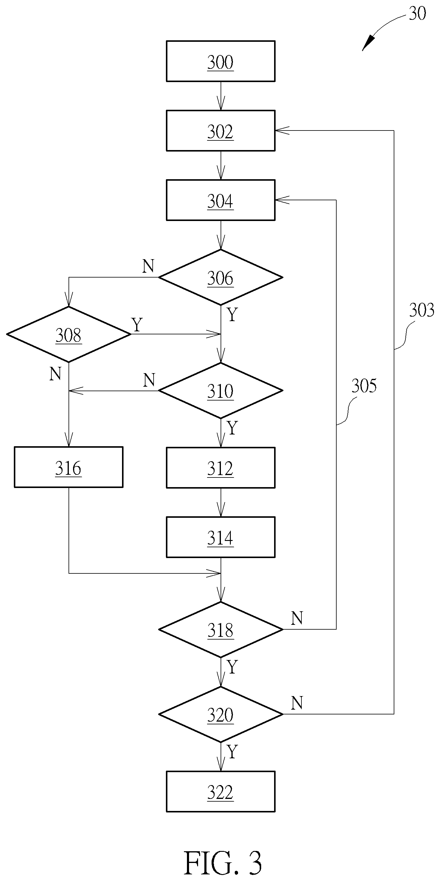
The user pairing operation in Table I may be iterated as a method 30, illustrated in FIG. 3 and executed by the processing unit 22. The method 30 comprises:
Step 300: Obtain the uplink set ULS and the downlink set DLS.
Step 302: Select the uplink user device UE.sub.DL,i* such that
.di-elect cons..times..times.> ##EQU00010##
Step 304: Select the downlink user device UE.sub.UL,j* such that
.di-elect cons..times..times.> ##EQU00011##
Step 306: Determine whether H.sub.i*.fwdarw.B.sup.U>H.sub.j*.fwdarw.B.sup.U. If yes, go to Step 310; otherwise, go to Step 308.
Step 308: Determine whether
>.ltoreq..times.>.times..theta. ##EQU00012## If yes, go to Step 310; otherwise, go to Step 316.
Step 310: Determine whether SINR.sub.j|i.gtoreq.SINR.sub.th. If yes, go to Step 312; otherwise, go to Step 316.
Step 312: Form the uplink user device UE.sub.UL,i* and the downlink user device UE.sub.DL,j* as a user pair (UE.sub.UL,i*, UE.sub.DL,j*), i.e., set x.sub.i*,j*=1.
Step 314: Remove the uplink user device UE.sub.UL,i* from the uplink set ULS to update the uplink set ULS and remove the downlink user device UE.sub.DL,j* from the downlink set DLS to update the downlink set DLS.
Step 316: Remove the downlink user device UE.sub.DL,j* from the downlink set DLS to update the downlink set DLS.
Step 318: Check if x.sub.i*,j*=1 or if there is no downlink device UE.sub.DL,j within the downlink set DLS can be paired with the uplink user device UE.sub.DL,i*. If yes, go to Step 320; otherwise, go to Step 304.
Step 320: Check if every uplink user device UE.sub.UL,i has been considered as uplink candidate of the user pair. If yes, go to Step 322; otherwise, go to Step 302.
Step 322: Determine the uplink transmission powers p.sub.i.sup.U for all i and the downlink transmission power P.sub.j.sup.D for all j.
Step 302 is corresponding to Line 7 (of Table I). Step 304 is corresponding to Line 9. Steps 306 and 310 are corresponding to the condition on Line 10. Steps 306, 308 and 310 are corresponding to the condition on Line 15. Step 312 is corresponding to Line 12 and/or Line 16. Step 314 is corresponding to Lines 13-14 and/or Lines 17-18. Step 316 is corresponding to Line 20. Step 318 is corresponding to the condition on Line 22. Step 320 is corresponding to the condition on Line 24. Steps 304-318 and Path 305 are corresponding to the loop structure of Lines 8-22. In Path 303, the uplink set ULS and the downlink set DLS (or, equivalently, the uplink index set US and the downlink index set DS) are updated, which corresponds to Line 23, Steps 302-320 with Path 305 and Path 303 are corresponding to the loop structure of Lines 6-24. After the processing unit 22 steps into Step 322, the processing unit 22 obtains a plurality of user pairs
In some embodiments, the channel gains above can be viewed as expected or estimated channel gains.
In summary, the present disclosure performs the user pairing operation to maximize the sum rate.
Those skilled in the art will readily observe that numerous modifications and alterations of the device and method may be made while retaining the teachings of the invention. Accordingly, the above disclosure should be construed as limited only by the metes and bounds of the appended claims.
* * * * *
D00000
D00001
D00002
D00003
M00001
M00002
M00003
M00004
M00005
M00006
M00007
M00008
M00009

M00010

M00011

M00012

XML
uspto.report is an independent third-party trademark research tool that is not affiliated, endorsed, or sponsored by the United States Patent and Trademark Office (USPTO) or any other governmental organization. The information provided by uspto.report is based on publicly available data at the time of writing and is intended for informational purposes only.
While we strive to provide accurate and up-to-date information, we do not guarantee the accuracy, completeness, reliability, or suitability of the information displayed on this site. The use of this site is at your own risk. Any reliance you place on such information is therefore strictly at your own risk.
All official trademark data, including owner information, should be verified by visiting the official USPTO website at www.uspto.gov. This site is not intended to replace professional legal advice and should not be used as a substitute for consulting with a legal professional who is knowledgeable about trademark law.