Systems and methods for multiband delta sigma digitization
Wang , et al. December 29, 2
U.S. patent number 10,880,006 [Application Number 16/834,631] was granted by the patent office on 2020-12-29 for systems and methods for multiband delta sigma digitization. This patent grant is currently assigned to Cable Television Laboratories, Inc. The grantee listed for this patent is CABLE TELEVISION LABORATORIES, INC. Invention is credited to Luis Alberto Campos, Zhensheng Jia, Jing Wang.


| United States Patent | 10,880,006 |
| Wang , et al. | December 29, 2020 |
Systems and methods for multiband delta sigma digitization
Abstract
A digital mobile fronthaul (MFH) network includes a baseband processing unit (BBU) having a digitization interface configured to digitize, using delta-sigma digitization, at least one wireless service for at least one radio access technology. The network further includes a transport medium in operable communication with the BBU. The transport medium is configured to transmit a delta-sigma digitized wireless service from the BBU. The network further includes a remote radio head (RRH) configured to operably receive the delta-sigma digitized wireless service from the BBU over the transport medium.
| Inventors: | Wang; Jing (Broomfield, CO), Jia; Zhensheng (Superior, CO), Campos; Luis Alberto (Superior, CO) | ||||||||||
|---|---|---|---|---|---|---|---|---|---|---|---|
| Applicant: |
|
||||||||||
| Assignee: | Cable Television Laboratories,
Inc (Louisville, CO) |
||||||||||
| Family ID: | 1000005271763 | ||||||||||
| Appl. No.: | 16/834,631 | ||||||||||
| Filed: | March 30, 2020 |
Prior Publication Data
| Document Identifier | Publication Date | |
|---|---|---|
| US 20200235814 A1 | Jul 23, 2020 | |
Related U.S. Patent Documents
| Application Number | Filing Date | Patent Number | Issue Date | ||
|---|---|---|---|---|---|
| 16191315 | Nov 14, 2018 | 10608744 | |||
| 62586041 | Nov 14, 2017 | ||||
| Current U.S. Class: | 1/1 |
| Current CPC Class: | H04Q 11/02 (20130101); H04Q 11/0071 (20130101); H04B 10/25753 (20130101); H04Q 11/0067 (20130101); H04B 10/541 (20130101); H04J 14/0226 (20130101); H04W 88/085 (20130101); H04J 14/0298 (20130101); H04B 2210/516 (20130101) |
| Current International Class: | H04B 10/2575 (20130101); H04Q 11/00 (20060101); H04J 14/02 (20060101); H04W 88/08 (20090101); H04Q 11/02 (20060101); H04B 10/54 (20130101) |
References Cited [Referenced By]
U.S. Patent Documents
| 2004/0223553 | November 2004 | Kumar |
| 2005/0099327 | May 2005 | Robinson |
| 2007/0066268 | March 2007 | Simic |
| 2007/0236374 | October 2007 | Brueske |
| 2009/0021409 | January 2009 | Mathe |
| 2012/0014694 | January 2012 | Templ |
| 2014/0159931 | June 2014 | Redfern |
| 2017/0085349 | March 2017 | Ho |
| 2017/0373890 | December 2017 | Fertonani |
| 2018/0026823 | January 2018 | Kumar |
Attorney, Agent or Firm: Armstrong Teasdale LLP
Parent Case Text
CROSS REFERENCE TO RELATED APPLICATIONS
This application is a continuation of U.S. patent application Ser. No. 16/191,315, filed Nov. 14, 2018, which prior application claims the benefit of and priority to U.S. Provisional Patent Application Ser. No. 62/586,041, filed Nov. 14, 2017, the disclosures of which are incorporated herein by reference in their entireties.
Claims
What is claimed is:
1. A digital mobile fronthaul (MFH) network, comprising: a baseband processing unit (BBU) including a digitization interface configured to (i) digitize, using delta-sigma digitization, at least one wireless service for at least one radio access technology into a delta-sigma digitized wireless service, and (ii) implement a noise transfer function corresponding to a signal band of the at least one wireless service; a digital transport medium (i) in operable communication with the BBU, and (ii) configured to transmit the delta-sigma digitized wireless service from the BBU; and a remote radio head (RRH) including a filter corresponding to the noise transfer function of the digitization interface, the RRH configured to (i) operably receive the delta-sigma digitized wireless service from the BBU over the digital transport medium, (ii) filter the received delta-sigma digitized wireless service into a filtered digital signal, and (iii) convert the filtered digital signal into an analog radio frequency (RF) signal.
2. The network of claim 1, wherein the digitization interface comprises a multiband delta-sigma analog-to-digital converter (ADC).
3. The network of claim 2, wherein the digitization interface further comprises a baseband processor, an RF up-converter, and a frequency domain multiplexer (FDM).
4. The network of claim 3, wherein the digital transport medium comprises an optical fiber.
5. The network of claim 4, wherein the digitization interface further comprises an electrical-to-optical interface at the optical fiber, and wherein the multiband delta-sigma ADC is disposed between the electrical-to-optical interface and the FDM.
6. The network of claim 5, wherein the digitization interface further comprises a wavelength division multiplexing multiplexer disposed between the electrical-to-optical interface and the multiband delta-sigma ADC, and wherein the wavelength division multiplexing multiplexer is configured to receive the delta-sigma digitized wireless service from the BBU and at least one different digitized wireless service from a different BBU.
7. A method for performing delta-sigma digitization of an aggregated signal including a plurality of different signal bands from a communication network, the method comprising the steps of: oversampling the aggregated signal at rate equal to an oversampling rate times the Nyquist sampling rate, to generate an oversampled signal and quantization noise; noise shaping the oversampled signal to implement a noise transfer function and push the quantization noise into out-of-band frequency spectra corresponding to respective spectral portions between the plurality of different signal bands; transmitting the noise shaped signal over a digital transport medium; and filtering the transmitted noise shaped signal, received from the digital transport medium, using a filter corresponding to the noise transfer function to remove the out-of-band quantization noise from the plurality of different signal bands.
8. The method of claim 7, wherein the step of oversampling comprises a substep of quantizing the aggregated signal.
9. The method of claim 8, wherein the substep of quantizing comprises one-bit quantization.
10. The method of claim 9, wherein the one-bit quantization implements a binary signal.
11. The method of claim 9, wherein the binary signal comprises on-off keying.
12. The method of claim 8, wherein the substep of quantizing comprises two-bit quantization.
13. The method of claim 12, wherein the two-bit comprises four-level pulse amplitude modulation.
14. The method of claim 7, wherein the plurality of different signal bands are contiguous.
15. The method of claim 14, wherein the plurality of different signal bands originate from a same wireless radio access technology.
16. The method of claim 7, wherein the plurality of different signal bands are non-contiguous.
17. The method of claim 16, wherein the plurality of different signal bands originate from a same wireless radio access technology.
18. The method of claim 16, wherein the plurality of different signal bands originate from different wireless radio access technologies.
19. The method of claim 17, wherein the plurality of different signal bands originate from a heterogeneous mobile fronthaul network.
20. The method of claim 7, wherein each frequency band of the plurality of different signal bands utilizes a single wireless service.
Description
BACKGROUND
The field of the disclosure relates generally to communication networks, and more particularly, to digitization techniques in access communication networks.
Emerging video-intensive and bandwidth-consuming services, such as virtual reality (VR), augmented reality (AR), and immersive applications, are driving the growth of wireless data traffic in a significant manner. This rapid growth has made the network segment of mobile fronthaul (MFH) networks a new bottleneck of user experience. Various technologies have been proposed and investigated to increase the spectral efficiency of MFH networks and enhance the quality of services (QoS) for end users, such as analog MFH based on radio-over-fiber (RoF) technology and digital MFH based on common public radio interface (CPRI), etc. These conventional proposals, however, have been unable to keep up with the increasing pace of growth of wireless traffic.
In a new paradigm of 5G new radio (5G-NR), heterogeneous MFH networks are proposed to aggregate wireless services from multiple radio access technologies (multi-RATs), and then deliver the aggregated services in a shared ubiquitous access network, as described further below with respect to FIG. 1.
FIG. 1 is a schematic illustration of a conventional access network architecture 100. Architecture 100 includes a core network 102, a baseband processing unit (BBU) pool 104, and one or more remote radio heads (RRHs) 106 (e.g., RRHs 106(1), and mobile users 106(2) and wireless users 106(3), which connect with a respective RRH 106(1)). Architecture 100 is, in this example, a cloud-radio access network (C-RAN) that includes a plurality of centralized BBUs 108 in BBU pool 104 to enable inter-cell processing. Core network 102 includes one or more service gateways (S-GWs) 110, or mobile management entities (MMEs), in operable communication with BBU pool 104 over a mobile backhaul (MBH) network 112. That is, MBH network 112 constitutes the network segment from S-GW/MME 110 to BBUs 108 or BBU pool 104. In a similar fashion, a mobile fronthaul (MFH) 114 is defined as the network segment from BBUs 108/BBU pool 104 to RRHs 106.
In operation of architecture 100, MBH 112 transmits digital bits 116 of net information, whereas MFH 114 transmits wireless services 118 in either an analog waveform 120 based on RoF technology, or in a digital waveform 122 using a digitization interface, such as CPRI. In the embodiment depicted in FIG. 1, architecture 100 represents a heterogeneous MFH network, for aggregating and delivering a plurality of services 124 from different radio access technologies (RATs), including Wi-Fi, 4G long term evolution (4G-LTE), and 5G-NR, to RRHs 106 by way of a shared fiber link 126. Service aggregation of the same RAT (e.g., Wi-Fi channel boning, LTE carrier aggregation (CA), etc.) is referred to as intra-RAT aggregation, whereas heterogeneous aggregation of services from different RATs is referred to as inter-RAT aggregation. A heterogeneous MFH network offers traffic offloading among different RATs and enhances the seamless coverage and provides a ubiquitous access experience to end users.
Accordingly, the conventional MFH technologies include: (1) analog MFH based on RoF technology, which is described further below with respect to FIGS. 2A-B; and (2) digital MFH based on CPRI, which is described further below with respect to FIGS. 3A-B.
FIG. 2A is a schematic illustration of a conventional analog MFH network 200. MFH network 200 includes at least one BBU 202 in operable communication with an RRH 204 over a transport medium 206 (e.g., an optical fiber). BBU 202 includes a baseband processing layer 208, an intermediate frequency (IF) up-conversion layer 210, a frequency domain multiplexer (FDM) 212, and an electrical-optical (E/O) interface 214. In a similar manner, RRH 204 includes a radio frequency (RF) front end 216, an RF up-conversion layer 218, a bandpass filter (BPF) 220, and an optical-electrical (O/E) interface 222.
In operation of MFH network 200, BBU 202 receives digital bits from MBH networks (not shown in FIG. 2A). The received bits are processed by baseband processing layer 208, which provides an OFDM signal to IF up-conversion layer 210 for synthesis and up-conversion to an intermediate frequency. Different wireless services are then multiplexed by FDM 212 in the frequency domain, and finally transmitted through E/O interface 214 to RRH 204 over an analog fiber link of transport medium 206. At RRH 204, after O/E interface 222, the different services are separated by bandpass filter(s) 220, and then up-converted by RF up-converter 218 to radio frequencies for wireless emission. Since these wireless services are carried on different intermediate frequencies (IFs) during fiber propagation, this operation is also referred to as intermediate frequency over fiber (IFoF).
FIG. 2B is a schematic illustration of a conventional analog MFH link 224 for network 200, FIG. 2A. In an exemplary embodiment, MFH 224 represents a system implementation of an analog MFH link based on RoF/IFoF technology, and includes a plurality of transmitters 226 (e.g., corresponding to a respective BBU 202) configured to transmit a plurality of respective signals 228 over link 206. Signals 228 are aggregated by FDM 212 prior to transmission over fiber 206 by E/O interface 214. The aggregated signals 228 are received by O/E interface 222, which provides signals 228 to respective receivers 230 (e.g., of a respective RRH 204). It can be seen from the embodiment depicted in FIG. 2B that the respective RF devices include mixers 232 and local oscillators 234, for both BBUs 202 and RRHs 204, for IF up-conversion and RF up-conversion, respectively. In this embodiment, transmitters 226 are depicted to illustrate the IF up-conversion.
Due to its high spectral efficiency, simple equalization in the frequency domain, and robustness against inter-symbol interference (ISI), orthogonal frequency-division multiplexing (OFDM) has been adopted by most RATs, including WiMAX, Wi-Fi (802.11), WiGig (802.11ad), 4G-LTE (3GPP), and 5G-NR. However, OFDM signals are vulnerable to nonlinear impairments due to their continuously varying envelope and high peak-to-average ratio (PAPR). Therefore, it has become increasingly difficult to support high order modulation formats (e.g., >256 QAM) using OFDM over MFH networks. To transmit the higher order formats required by LTE and 5G-NR signals without nonlinear distortions, digital MFH networks based digitization interfaces, such as CPRI, has been proposed and implemented. A digital MFH network is described below with respect to FIGS. 3A-B.
FIG. 3A is a schematic illustration of a conventional digital MFH network 300. Digital MFH network 300 is similar to analog MFH network 200, FIG. 2, in many respects, and includes at least one BBU 302 in operable communication with an RRH 304 over a transport medium 306 (e.g., an optical fiber). Network 300 differs from network 200 though, in that network 300 transmits mobile services using digital waveforms over medium 206, which is implemented by the digitization interface of CPRI. BBU 302 includes a baseband processing layer 308, a Nyquist analog-to-digital converter (ADC) 310, a first time division multiplexer/demultiplexer (TDM) 312, and an electrical-optical (E/O) interface 314. In a similar manner, RRH 304 includes an RF front end 316, an RF up-converter 318, a Nyquist digital-to-analog converter (DAC) 320, a second TDM 322, and an optical-electrical (O/E) interface 324.
FIG. 3B is a schematic illustration of a conventional digital MFH link 326 for network 300, FIG. 3A. In an exemplary embodiment, MFH 326 includes a plurality of transmitters 328 (e.g., corresponding to a respective BBU 302) configured to transmit a plurality of respective bit streams 330 over fiber link 306. Operation of network 300 therefore differs from that of network 200, in that, after baseband processing (e.g., by baseband processing layer 308), the waveforms of baseband signals from processor 308 are digitized into bits 330 by Nyquist ADC 310. The digitized bits 330 are then transported to respective receivers 332 (e.g., of a respective RRH 304) over a digital fiber link (e.g., transport medium 306) based on mature optical intensity modulation-direct detection (IM-DD) technology. In the configuration depicted in FIG. 3B, the waveforms of the in-phase (I) and quadrature (Q) components of each wireless service are sampled and quantized separately, and the bits 330 from I/Q components of the different services are multiplexed in the time by first TDM 312. At the respective RRHs 304, after time division de-multiplexing by second TDM 322, Nyquist DAC 320 recovers the I/Q waveforms from received bits 334, which are then up-converted by RF up-converter 318 to RF frequencies and fed to RF front end 316.
Thus, when compared with analog MFH network 200 based on RoF/IFoF technology, digital MFH network 300 demonstrates an improved resilience against nonlinear impairments, and may be implemented by existing digital fiber links, such as, for example, a passive optical network (PON). However, these conventional digital MFH networks suffer from the fact that CPRI has a significantly low spectral efficiency, and may only accommodate few narrowband RATs, such as UMTS (CPRI v1 and v2), WiMAX (v3), LTE (v4), and GSM (v5). Additionally, because CPRI uses TDMs to aggregate services, time synchronization is an additional challenge to the coexistence of multiple RATs with different clock rates. With the low spectral efficiency and the lack of support to Wi-Fi and 5G-NR, CPRI has proven to be a technically-infeasible and cost-prohibitive digitization interface for 5G heterogeneous MFH networks. Accordingly, it is desirable to develop more universal digitization techniques that enable cost-effective carrier aggregation of multiple RATs (multi-RATs) in the next generation heterogeneous MFH networks.
BRIEF SUMMARY
In an embodiment, a digital mobile fronthaul (MFH) network includes a baseband processing unit (BBU) having a digitization interface configured to digitize, using delta-sigma digitization, at least one wireless service for at least one radio access technology. The network further includes a transport medium in operable communication with the BBU. The transport medium is configured to transmit a delta-sigma digitized wireless service from the BBU. The network further includes a remote radio head (RRH) configured to operably receive the delta-sigma digitized wireless service from the BBU over the transport medium.
In an embodiment, a method for performing delta-sigma digitization of an aggregated signal is provided. The aggregated signal includes a plurality of different signal bands from a communication network. The method includes steps of oversampling the aggregated signal at rate equal to an oversampling rate times the Nyquist sampling rate to generate an oversampled signal and quantization noise, noise shaping the oversampled signal to push the quantization noise into out-of-band frequency spectra corresponding to respective spectral portions between the plurality of different signal bands, and filtering the noise shaped signal to remove the out-of-band quantization noise from the plurality of different signal bands.
BRIEF DESCRIPTION OF THE DRAWINGS
These and other features, aspects, and advantages of the present disclosure will become better understood when the following detailed description is read with reference to the accompanying drawings in which like characters represent like parts throughout the drawings, wherein:
FIG. 1 is a schematic illustration of a conventional access network architecture.
FIG. 2A is a schematic illustration of a conventional analog mobile fronthaul network.
FIG. 2B is a schematic illustration of a conventional analog mobile fronthaul link for the network depicted in FIG. 2A.
FIG. 3A is a schematic illustration of a conventional digital mobile fronthaul network.
FIG. 3B is a schematic illustration of a conventional digital mobile fronthaul link for the network depicted in FIG. 3A.
FIG. 4A is a schematic illustration of a digital mobile fronthaul network according to an embodiment of the present disclosure.
FIG. 4B is a schematic illustration of a digital mobile fronthaul link for the network depicted in FIG. 4A.
FIG. 5 is a graphical illustration depicting a conventional digitization process.
FIGS. 6A-C are graphical illustrations depicting a digitization process according to an embodiment of the present disclosure.
FIGS. 7A-C are graphical illustrations depicting respective applications of the digitization process depicted in FIGS. 6A-C.
FIG. 8 is a schematic illustration of a mobile fronthaul link implementing wavelength division multiplexing, according to an embodiment of the present disclosure.
FIG. 9 is a schematic illustration of a mobile fronthaul link implementing power division multiplexing, according to an embodiment of the present disclosure.
FIG. 10 is a graphical illustration depicting an operating principle of the link depicted in FIG. 9.
Unless otherwise indicated, the drawings provided herein are meant to illustrate features of embodiments of this disclosure. These features are believed to be applicable in a wide variety of systems including one or more embodiments of this disclosure. As such, the drawings are not meant to include all conventional features known by those of ordinary skill in the art to be required for the practice of the embodiments disclosed herein.
DETAILED DESCRIPTION
In the following specification and the claims, reference will be made to a number of terms, which shall be defined to have the following meanings.
The singular forms "a," "an," and "the" include plural references unless the context clearly dictates otherwise.
"Optional" or "optionally" means that the subsequently described event or circumstance may or may not occur, and that the description includes instances where the event occurs and instances where it does not.
Approximating language, as used herein throughout the specification and claims, may be applied to modify any quantitative representation that could permissibly vary without resulting in a change in the basic function to which it is related. Accordingly, a value modified by a term or terms, such as "about," "approximately," and "substantially," are not to be limited to the precise value specified. In at least some instances, the approximating language may correspond to the precision of an instrument for measuring the value. Here and throughout the specification and claims, range limitations may be combined and/or interchanged; such ranges are identified and include all the sub-ranges contained therein unless context or language indicates otherwise.
According to the embodiments described herein, multiband delta-sigma digitization systems and methods enable carrier aggregation of multi-RATs in next generation heterogeneous MFH networks. The present multiband delta-sigma ADC techniques allow different RAT technologies, such as, 4G-LTE, Wi-Fi, and 5G-NR signals, to be aggregated and delivered together with shared MFH networks. The present embodiments advantageously enable the aggregation of heterogeneous wireless services from multi-RATs in the frequency domain, and then the digitization of the aggregated services simultaneously in an "as is" manner, that is, without frequency conversion.
These advantageous configurations are thus able to circumvent clock rate compatibility and time synchronization problems arising from multi-RAT coexistence, while also eliminating the need of DAC and RF devices at remote cell cites (e.g., RRHs), thereby further enabling a low-cost, all-analog implementation of RRHs where desired. The present embodiments further significantly reduce the cost and complexity of 5G small cells, while also facilitating large-scale dense deployment of heterogeneous 5G MFH networks. The present systems and methods further provide an innovative digitization interface advantageously replaces CPRI, thereby realizing a significantly higher spectral efficiency, while also offering improved compatibility for multi-RAT coexistence in 5G heterogeneous MFH networks.
FIG. 4A is a schematic illustration of a digital MFH network 400. Network 400 is similar to networks 200, FIG. 2A, 300, FIG. 3A in a number of respects, but represents an improved digitization interface for implementing multiband delta-sigma digitization. MFH network 400 includes at least one BBU 402 in operable communication with an RRH 404 over a transport medium 406 (e.g., an optical fiber). BBU 402 includes a baseband processor 408, an RF up-converter 410, a delta-sigma ADC 412, and an E/O interface 414. In a similar manner, RRH 404 includes an RF front end 416, a BPF 418, and an O/E interface 420.
FIG. 4B is a schematic illustration of a digital MFH link 422 for network 400, FIG. 4A. In exemplary operation of link 422, at respective transmitters 424 (e.g., of respective BBUs 402), after baseband processing by baseband processor 408, a plurality of various wireless services 426 (e.g., from different RATs) are up-converted by RF up-converter 410 to RF frequencies, and then aggregated in the frequency domain by an FDM 428. The wireless signals of aggregated services 426 are then digitized by delta-sigma ADC 412 (e.g., a multiband delta-sigma ADC) to generate a digitized delta-sigma data stream 430. In the exemplary embodiment, delta-sigma ADC 412 digitizes multiband signals/services 426 simultaneously. Unlike Nyquist ADC techniques used in CPRI (e.g., by Nyquist ADC 310, FIG. 3), which only digitize baseband signals, multiband delta-sigma ADC 412 is advantageously able to digitize wireless services 426 in an "as is" manner, without the need of frequency down-conversion.
In the exemplary embodiment depicted in FIG. 4B, transmitters 424 are depicted, for example, to illustrate the RF up-conversion of I and Q components of different wireless services. Further to this example, in this architecture, respective RF devices, including without limitation local oscillators 432, mixers 434, and delta-sigma ADCs 412 may all be advantageously centralized in BBU 402, whereas only BPFs 418 and respective antennas of RF front ends 416 are needed in RRHs 404. This simplified design enables a DAC-free and RF-free RRH, which may be further advantageously implemented by essentially all relevant analog devices. This configuration is particularly advantageous with respect to the 5G paradigm, given the wide and dense deployment of small cells. That is, an all-analog, DAC-free, RF-free architecture (i.e., according to FIGS. 4A-B) will significantly reduce the cost and complexity of existing and future RRHs.
In the embodiments depicted in FIGS. 4A-B, the digital MFH architecture is depicted to implement FDM (e.g., FDM 428) to multiplex wireless services (e.g., services 426), and analog BPFs (e.g., BPFs 418) to separate the multiplexed wireless services. This configuration thus avoids the compatibility problem of different baseband chip rates for various RATs, and also circumvents the synchronization problem experienced among the different services. Furthermore, the delta-sigma digitization techniques of the present embodiments provide a waveform-agnostic interface, which not only supports OFDM, but also works with other multicarrier waveforms, such as filter bank multicarrier (FBMC), universal filtered multicarrier (UFMC), etc.
FIG. 5 is a graphical illustration depicting a conventional digitization process 500. Sampling process 500 depicts the operation of a conventional Nyquist ADC used in CPRI for an analog signal 502 (shown in the time domain). In operation, process 500 bandwidth-limits analog signal 502 as a corresponding frequency domain signal 504 using a low-pass filter. That is, in the frequency domain, analog signal 502 is bandwidth limited to digital signal 504. After digitization, quantization noise 506 is uncorrelated with the frequency of the input signal, and is spread evenly over the Nyquist zone f.sub.s/2. In the time domain, process 500 performs Nyquist sampling 508 of analog signal 502 (i.e., at the Nyquist frequency), and quantizes each obtained sample by multiple quantization bits to produce multi-bit quantization signal 510.
Since the quantization noise of a Nyquist ADC is approximately Gaussian, as well as uniformly spread over the Nyquist zone, a very large number of quantization bits are needed to ensure the signal-to-noise ratio (SNR) (e.g., CNR or MER) of the resulting digitized signals 510. Such a large number of required quantization bits leads to low spectral efficiency, as well as a data rate bottleneck of MFH networks.
More specifically, as depicted in FIG. 5, in conventional CPRI Nyquist ADC, each LTE carrier is digitized individually by a Nyquist ADC having, for example, a sampling rate of 30.72 MSa/s. For each sample, 15 quantization bits and one control bit (16 bits total) are used to represent the analog amplitude. The quantization noise (e.g., quantization noise 506) of a Nyquist ADC is evenly distributed in the Nyquist zone in the frequency domain, which can be approximated by Gaussian white noise.
To reduce the quantization noise and increase the SNR of digitized signal, CPRI requires a large number of quantization bits, thereby resulting in the low spectral efficiency and significant bandwidth after digitization, which render CPRI the data rate bottleneck of digital MFH networks. In the case of line coding of 8b/10b, CPRI will consume up to 30.72 MSa/s*16 bit/Sa*10/8*2=1.23 Gb/s of MFH capacity for each 20 MHz LTE carrier. Within a 10-Gb/s PON link, for example, CPRI is only capable of accommodating eight LTE carriers.
Additionally, CPRI is known to operate at a fixed chip rate of 3.84 MHz, and to only support a limited number of RATs, such as UMTS (CPRI v1 and v2), WiMAX (v3), LTE (v4), and GSM (v5). Given the different clock rates of various RATs, time synchronization remains a problem for multi-RAT coexistence. Moreover, the low spectral efficiency and inability to support to Wi-Fi and 5G-NR render CPRI technically lacking and cost-prohibitive as a digitization interface for 5G heterogeneous MFH networks. These drawbacks are solved through implementation of the following innovative processes.
FIGS. 6A-C are graphical illustrations depicting a digitization process 600. In an exemplary embodiment, process 600 demonstrates an operational principle of the multiband delta-sigma ADC techniques described herein, and may be executed by a processor (not shown in FIGS. 6A-C) in one or more BBUs. More specifically, FIG. 6A depicts an oversampling subprocess 602 of process 600, FIG. 6B depicts a noise shaping subprocess 604 of process 600, and FIG. 6C depicts a filtering subprocess 606 of process 600.
In an exemplary embodiment of oversampling subprocess 602, quantization noise 608 is spread over a relatively wide Nyquist zone (e.g., the oversampling rate (OSR) times the Nyquist sampling rate f.sub.s/2, or OSR*f.sub.s/2). In this example, because the quantization number is limited to one or two quantization bits, namely, one-bit quantization 610 (e.g., a binary, or on-off keying (OOK) signal) or two-bit quantization 612 (e.g., a PAM4 signal), quantization noise 608 is significant. In the exemplary embodiment depicted in FIGS. 6A-C, three non-contiguous signal bands 614 of wireless services are aggregated together. In some embodiments, signal bands 614 come from the same RAT (e.g., intra-RAT carrier aggregation). In other embodiments, signal bands 614 come from different RATs (e.g., inter-RAT carrier aggregation). Oversampling subprocess 602 and thus results in an oversampled analog signal 616.
In an exemplary embodiment of noise shaping subprocess 604, quantization noise 608' is pushed out of the signal bands 614, thereby separating signals from noise in the frequency domain. In this example of subprocess 604, the respective spectra of signal bands 614 are not modified during the operation of digitization process 600. In an exemplary embodiment of filtering subprocess 606, bandpass filters 616 are respectively applied to signal bands 614 to substantially eliminate the out-of-band (OOB) noise (e.g., quantization noise 608') and thereby enable retrieval of an output signal 618 closely approximating the original analog waveform.
This advantageous technique thus represents a significant improvement over the conventional Nyquist ADC techniques described above with respect to FIG. 5. More particularly, through implementation of a multiband delta-sigma ADC according to the operational principles of process 600, the known shortcomings of CPRI may be successfully circumvented. For example, instead of the large number of quantization bits required by conventional CPRI techniques, the present delta-sigma ADC embodiments successfully "trade" quantization bits for the sampling rates described herein. The present techniques thus exploit a high sampling rate, but only require relatively few (i.e., one or two) quantization bits to be fully implemented.
In the exemplary embodiments depicted in FIGS. 6A-C, the OOB quantization noise (e.g., quantization noise 608') is added by the delta-sigma ADC (not shown in FIGS. 6A-C), and which converts the original signal waveform from analog to digital. At the RRH, the original analog waveform (e.g., output signal 618) may then be easily retrieved once the quantization noise is eliminated by filtering (e.g., filtering subprocess 606). From the noise shaping technique of noise shaping subprocess 604 though, the retrieved analog signal may have an uneven noise floor. Accordingly, in an embodiment, the noise shaping technique may be configured to exploit a noise transfer function to control the frequency distribution of quantization noise 608', where each conjugate pair of zero points of the noise transfer function corresponds to a null point of noise. In the design of a multiband delta-sigma ADC, one or two pairs of zeros of the noise transfer function may be assigned to each signal band 614, depending on the bandwidth.
The operational principles of the present delta-sigma ADC may also be advantageously interpreted in the time domain. The present delta-sigma ADC techniques have, for example, a memory effect, whereas conventional Nyquist ADC techniques have no such memory effect. Conventional Nyquist ADC operations quantize each sample individually and independently, and the resultant output bits are only determined by the input amplitude for that particular sample, which has no dependence on previous samples. In contrast, the present delta-sigma ADC techniques are able to digitize samples consecutively whereby a particular output bit may depend not only on the particular input sample, but also on previous samples.
For example, in the case of a sinusoidal analog input, a one-bit delta-sigma ADC according to the present embodiments outputs a high speed OOK signal with a density of "1" bits, proportional to the amplitude of analog input. Thus, when the input is close to its maximum value, the output will include almost all "1" bits. However, when the input is close to its minimum value, the output will include all "0" bits. Similarly, for intermediate inputs, the output will be expected to have an equal density of "0" and "1" bits.
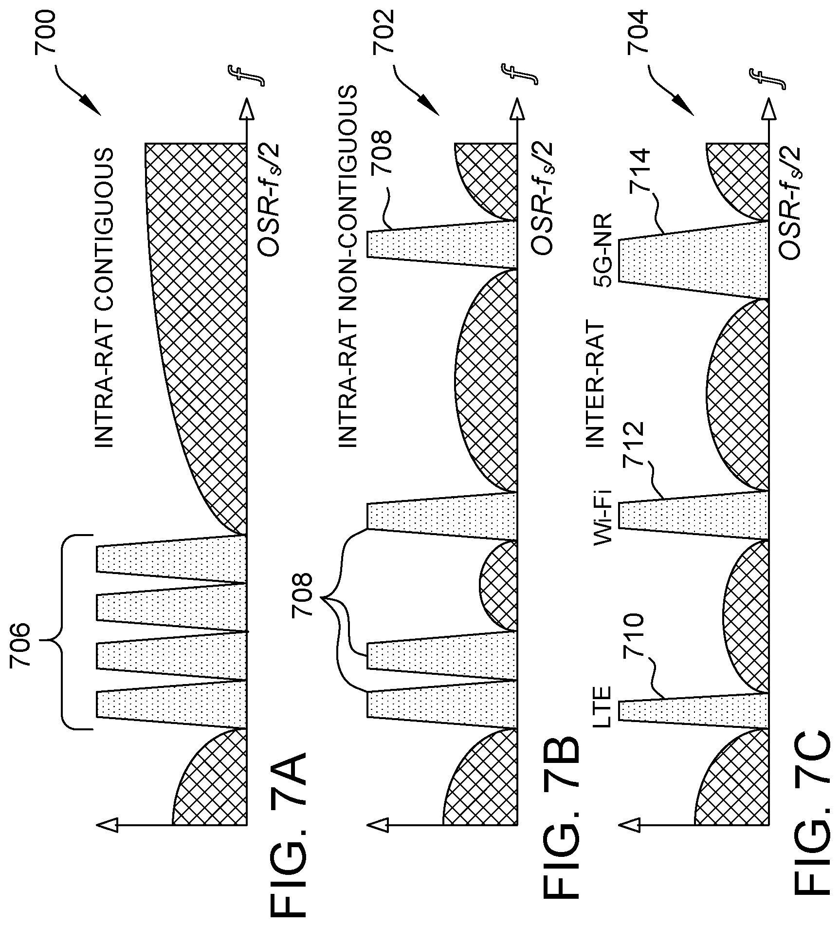
FIGS. 7A-C are graphical illustrations depicting respective applications 700, 702, 704 of digitization process 600, FIGS. 6A-C (e.g., after noise filtering subprocess 604). More specifically, application 700 depicts a case of intra-RAT contiguous carrier aggregation, application 702 depicts a case of intra-RAT non-contiguous carrier aggregation, and application 704 depicts a case of heterogeneous inter-RAT carrier aggregation.
In an exemplary embodiment of application 700, a case of intra-RAT contiguous carrier aggregation may occur where wireless services 706 from the same RAT are bonded together contiguously in the frequency domain, and digitized simultaneously by a single-band delta-sigma ADC. Examples of this scenario include LTE contiguous carrier aggregation and Wi-Fi channel bonding.
In an exemplary embodiment of application 702, a case of intra-RAT non-contiguous carrier aggregation may occur where wireless services 708 from the same RAT are aggregated non-contiguously, and digitized together by a multiband delta-sigma ADC. Examples of this scenario include LTE non-contiguous carrier aggregation.
In an exemplary embodiment of application 704, a case of heterogeneous inter-RAT carrier aggregation may occur where respective wireless services 710, 712, 714 from different RATs (e.g., an LTE RAT for service 710, a Wi-Fi RAT for service 712, and a 5G-NR RAT for service 714) are aggregated in a heterogeneous MFH network. As illustrated in this embodiment, a waveform/RAT-agnostic digitization interface is provided that eliminates the need for DAC and RF devices in RRHs, while also supporting multiband wireless services with different carrier frequencies and bandwidths from multiple RATs, without presenting the synchronization or compatibility problems experienced by conventional digitization interfaces.
In the embodiments depicted in FIGS. 7A-C, each frequency band is utilized by only one wireless service. Other application scenarios of frequency sharing, such as in the case where one frequency component is occupied by more than one wireless signals (e.g., frequency overlap among multiple RATs or multiple-input multiple-output (MIMO)) are contemplated, but not illustrated in this example. Various frequency ranges of different RATs, including overlaps, are illustrated below in Table 1.
TABLE-US-00001 TABLE 1 LTE RAT Wi-Fi (802.11) WiMAX 3 GPP UWB Protocol a g n ac/ax af ah 802.16 e (rel. 8) 802.15.3a Freq. bands 5.15-5.875 2.4-2.497 5.15-5.875, 5.15-5.875 0.054-0.698, <1- 2.1-5.9 0.7-2.6 3.168-10.56 (GHz) 2.4-2.497 0.47-0.79
As can be seen from the information provided in Table 1, problems occur as a result of frequency reuse. As described further below with respect to FIGS. 8 and 9, respectively, the present systems and methods provide further solutions to overcome the problems of frequency reuse based on wavelength division multiplexing (WDM) and power division multiplexing (PDM) technologies.
FIG. 8 is a schematic illustration of an MFH link 800 implementing WDM. MFH link 800 is similar in some structural respects to MFH link 400, FIG. 4, and includes a first group of transmitters 802 and a second group of transmitters 804 in operational communication with a first FDM 806 and a second FDM 808, respectively. Additionally, first FDM 806 and second FDM 808 are also in operational communication with a first delta-sigma ADC 810 and a second delta-sigma ADC 812, respectively. In an exemplary embodiment of MFH link 800, multiple wireless services at the same RF frequencies may be advantageously digitized and supported by different wavelengths using WDM technology.
More particularly, digital bit streams from first and second delta-sigma ADCs 810, 812 are carried by different wavelengths .lamda..sub.1 and .lamda..sub.2, respectively, and then multiplexed by a WDM multiplexer 814 onto a single fiber transport medium 816. In the example depicted in FIG. 8, a first OOK.sub.1 is carried on wavelength .lamda..sub.1, which supports three wireless services 818 at respective frequencies of f.sub.RF1, f.sub.RF2, and f.sub.RF3, and a second OOK.sub.2 is carried on wavelength .lamda..sub.2, which supports three different wireless services 820 at respective frequencies of f.sub.RF4, f.sub.RF5, and f.sub.RF6. Further in this example, the frequencies f.sub.RF2=f.sub.RF5; however, the two wavelengths .lamda..sub.1 and .lamda..sub.2 are separated at first RRH 822 and second RRH 824 by a WDM de-multiplexer 826. Thus, the separate services f.sub.RF2 and f.sub.RF5 may be filtered out by corresponding filters 828 (e.g., BPF.sub.2 and BPF.sub.5, respectively, in this example).
FIG. 9 is a schematic illustration of an MFH link 900 implementing PDM. MFH link 900 is similar to MFH link 800, FIG. 8, and includes a first group of transmitters 902 and a second group of transmitters 904 in operational communication with a first FDM 906 and a second FDM 908, respectively. Additionally, first FDM 906 and second FDM 908 are also in operational communication with a first delta-sigma ADC 910 and a second delta-sigma ADC 912, respectively. In an exemplary embodiment of MFH link 900, multiple wireless services at the same RF frequencies may be advantageously supported by different power levels using PDM technology.
More particularly, a first digitized bit stream 914 from first delta-sigma ADC 910 and a second digitized bit stream 916 from second delta-sigma ADC 912 have different amplitudes and may be superimposed in the power domain by a power combiner 918. That is, in MFH link 900, the two digitized bit streams 914, 916 of differing amplitudes are multiplexed in the power division and synthesized to a single 4-level pulse amplitude modulation (PAM4) signal 920. A signal 920 may then be delivered from first and second transmitter groups 902, 904 (e.g., of respective BBUs) to corresponding first and second RRH groups 922, 924, respectively over a single fiber transport medium 926.
Similar to the embodiment depicted in FIG. 8, in MFH link 900, first digitized bit stream 914 represents an OOK.sub.1 signal carrying wireless services 928 at respective frequencies of f.sub.RF1, f.sub.RF2, and f.sub.RF3, and second digitized bit stream 916 represents an OOK.sub.2 signal carrying different wireless services 930 at respective frequencies of f.sub.RF4, f.sub.RF5, and f.sub.RF6. However, in this example, the amplitude of OOK.sub.1 is twice that of OOK.sub.2, and thus the summation of the OOK.sub.1 and OOK.sub.2 signals synthesize PAM4 signal 920 (described further below with respect to FIG. 10). Also similar to the example depicted in FIG. 8, again frequencies f.sub.RF2=f.sub.RF5. In further operation of MFH link 900, prior to reception by first and second RRH groups 922, 924, and further downstream from an O/E interface 932 (e.g., a photodetector), and OOK receiver 934 is configured to retrieve the OOK.sub.1 signal, and a PAM4 receiver 936 is configured to retrieve the OOK.sub.2 signal. In this example, the relatively larger offset imposed by the OOK.sub.1 signal is removed before MFH link 900 is able to retrieve the relatively smaller amplitude of the OOK.sub.2 signal.
FIG. 10 is a graphical illustration depicting an operating principle 1000 of MFH link 900, FIG. 9. In an exemplary embodiment, operating principle 1000 depicts a synthesis effect of PDM using the present delta-sigma digitization techniques. More particularly, operating principle 1000 illustrates the synthesis of PAM4 signal 920 by the summation (e.g., by power combiner 918) of the OOK.sub.1 signal of first digitized bit stream 914 and the OOK.sub.2 signal of the second digitized bit stream 916. The amplitude ratio of OOK.sub.1 signal and the OOK.sub.2 signal is 2:1.
According to the embodiments described herein, innovative multiband delta-sigma digitization are provided that are advantageously capable of supporting heterogeneous carrier aggregations in 5G heterogeneous mobile fronthaul networks, including without limitation, 4G-LTE, Wi-Fi, and 5G-NR. The advantageous systems and methods of the present embodiments are further capable of aggregating heterogeneous wireless services in the frequency domain, thereby avoiding the baseband clock rate compatibility and time-synchronization problems arising from multi-RAT coexistence. The present techniques are further capable of digitizing multiband wireless services simultaneously, in an "as is" manner, without requiring frequency conversion, and thereby eliminating the need for DAC and RF devices at RRHs. By providing a significantly lower-cost and efficient all-analog implementation capability for RRHs the present systems and methods are particularly useful to significantly reduce RRH cost and complexity, which will facilitate wide dense deployment of 5G small cells.
The embodiments described herein further propose respective solutions based on wavelength/power division multiplexing (WDM/PDM) technologies to accommodate more than one wireless service at the same frequency. These additional embodiments therefore further enable frequency sharing among multiple RATs and MIMO deployments. Additional exemplary systems and methods for implementing delta-sigma digitization are described in co-pending U.S. patent application Ser. No. 15/847,417, filed Dec. 19, 2017, and to U.S. patent application Ser. No. 16/180,591, filed Nov. 5, 2018, the disclosures of both of which are incorporated by reference herein.
Although specific features of various embodiments of the disclosure may be shown in some drawings and not in others, this is for convenience only. In accordance with the principles of the disclosure, a particular feature shown in a drawing may be referenced and/or claimed in combination with features of the other drawings.
Exemplary embodiments of multiband delta-sigma digitization systems and methods are described above in detail. The systems and methods of this disclosure though, are not limited to only the specific embodiments described herein, but rather, the components and/or steps of their implementation may be utilized independently and separately from other components and/or steps described herein. Additionally, the exemplary embodiments described herein may be implemented and utilized in connection with access networks other than WFH and MBH networks.
Some embodiments involve the use of one or more electronic or computing devices. Such devices typically include a processor or controller, such as a general purpose central processing unit (CPU), a graphics processing unit (GPU), a microcontroller, a reduced instruction set computer (RISC) processor, an application specific integrated circuit (ASIC), a programmable logic circuit (PLC), a field programmable gate array (FPGA), a DSP device, and/or any other circuit or processor capable of executing the functions described herein. The processes described herein may be encoded as executable instructions embodied in a computer readable medium, including, without limitation, a storage device and/or a memory device. Such instructions, when executed by a processor, cause the processor to perform at least a portion of the methods described herein. The above examples are exemplary only, and thus are not intended to limit in any way the definition and/or meaning of the term "processor."
This written description uses examples to disclose the embodiments, including the best mode, and also to enable any person skilled in the art to practice the embodiments, including making and using any devices or systems and performing any incorporated methods. The patentable scope of the disclosure is defined by the claims, and may include other examples that occur to those skilled in the art. Such other examples are intended to be within the scope of the claims if they have structural elements that do not differ from the literal language of the claims, or if they include equivalent structural elements with insubstantial differences from the literal language of the claims.
* * * * *
D00000
D00001
D00002
D00003
D00004
D00005
D00006
D00007
D00008
D00009
D00010
XML
uspto.report is an independent third-party trademark research tool that is not affiliated, endorsed, or sponsored by the United States Patent and Trademark Office (USPTO) or any other governmental organization. The information provided by uspto.report is based on publicly available data at the time of writing and is intended for informational purposes only.
While we strive to provide accurate and up-to-date information, we do not guarantee the accuracy, completeness, reliability, or suitability of the information displayed on this site. The use of this site is at your own risk. Any reliance you place on such information is therefore strictly at your own risk.
All official trademark data, including owner information, should be verified by visiting the official USPTO website at www.uspto.gov. This site is not intended to replace professional legal advice and should not be used as a substitute for consulting with a legal professional who is knowledgeable about trademark law.