Aerial devices capable of controlled flight
Kovac , et al. December 29, 2
U.S. patent number 10,875,641 [Application Number 15/578,532] was granted by the patent office on 2020-12-29 for aerial devices capable of controlled flight. This patent grant is currently assigned to Imperial College of Science, Technology and Medicine. The grantee listed for this patent is Imperial College of Science, Technology and Medicine. Invention is credited to Mirko Kovac, Pooya Sareh.


View All Diagrams
| United States Patent | 10,875,641 |
| Kovac , et al. | December 29, 2020 |
Aerial devices capable of controlled flight
Abstract
An aerial device (100) capable of controlled flight has a body (110), a rotor (120) arranged to rotate relative to the body; and a deployable sheet (130), the sheet having an undeployed configuration in which the sheet is folded against the body and a deployed configuration in which the sheet is at least partially unfolded away from the body.
| Inventors: | Kovac; Mirko (London, GB), Sareh; Pooya (London, GB) | ||||||||||
|---|---|---|---|---|---|---|---|---|---|---|---|
| Applicant: |
|
||||||||||
| Assignee: | Imperial College of Science,
Technology and Medicine (London, GB) |
||||||||||
| Family ID: | 1000005267874 | ||||||||||
| Appl. No.: | 15/578,532 | ||||||||||
| Filed: | May 27, 2016 | ||||||||||
| PCT Filed: | May 27, 2016 | ||||||||||
| PCT No.: | PCT/GB2016/051567 | ||||||||||
| 371(c)(1),(2),(4) Date: | November 30, 2017 | ||||||||||
| PCT Pub. No.: | WO2016/193690 | ||||||||||
| PCT Pub. Date: | December 08, 2016 |
Prior Publication Data
| Document Identifier | Publication Date | |
|---|---|---|
| US 20180155018 A1 | Jun 7, 2018 | |
Foreign Application Priority Data
| Jun 1, 2015 [GB] | 1509509.4 | |||
| Jan 4, 2016 [GB] | 1600130.7 | |||
| Current U.S. Class: | 1/1 |
| Current CPC Class: | B64C 27/20 (20130101); B64C 39/024 (20130101); B64C 25/10 (20130101); B64D 45/04 (20130101); B64C 29/0016 (20130101); B64C 2201/165 (20130101); B64C 2201/162 (20130101); B64C 2203/00 (20130101); B64C 2201/027 (20130101) |
| Current International Class: | B64C 29/00 (20060101); B64D 45/04 (20060101); B64C 27/20 (20060101); B64C 25/10 (20060101); B64C 39/02 (20060101) |
References Cited [Referenced By]
U.S. Patent Documents
| 6322021 | November 2001 | Fisher et al. |
| 9527596 | December 2016 | Adams |
| 2002/0060267 | May 2002 | Yavnai |
| 2006/0016930 | January 2006 | Pak |
| 2009/0008507 | January 2009 | Pearson |
| 2014/0061362 | March 2014 | Olm et al. |
| 2017/0057630 | March 2017 | Schwaiger |
| 1193168 | Apr 2002 | EP | |||
| 1988014 | Dec 2010 | EP | |||
| 2336022 | Jun 2011 | EP | |||
| 101461059 | Nov 2014 | KR | |||
| WO9530575 | Nov 1995 | WO | |||
| WO2014080388 | May 2014 | WO | |||
| WO2015124556 | Aug 2015 | WO | |||
Other References
|
GB Search Report for corresponding GB Application No. GB1600130.7 dated Jun. 27, 2016, 9 pages. cited by applicant . PCT Search Reported for corresponding PCT International Application No. PCT/GB2016/051567 dated Jun. 1, 2015, 9 pages. cited by applicant. |
Primary Examiner: Bonnette; Rodney A
Attorney, Agent or Firm: Lee & Hayes, P.C.
Claims
The invention claimed is:
1. An aerial device capable of controlled flight, the aerial device comprising: a body; a rotor arranged to rotate relative to the body; and a deployable sheet, the sheet having an undeployed configuration in which the sheet is folded against the body and a deployed configuration in which the sheet is at least partially unfolded away from the body, wherein the sheet comprises at least one crease, and wherein the at least one crease of the sheet is scored or perforated.
2. The aerial device of claim 1, wherein the sheet comprises a plurality of creases that define a tessellated surface thereof, and wherein the tessellated surface comprises a plurality of parallelograms defined by the creases.
3. The aerial device of claim 1, wherein the rotor is arranged to rotate in a plane and wherein, in the deployed configuration, the sheet is at least partially unfolded away from the body in a direction parallel to the plane.
4. The aerial device of claim 1 further comprising an actuator operable to deploy the sheet from the undeployed configuration to the deployed configuration and/or to undeploy the sheet from the deployed configuration to the undeployed configuration.
5. The aerial device of claim 4 further comprising a controller arranged to operate the actuator, and at least one sensor for generating sensor data relating to a surrounding environment in which the aerial device is controllably flown, wherein the controller is arranged to operate the actuator based on the sensor data.
6. The aerial device of claim 5, wherein the sensor data includes data relating to a distance between the aerial device and a potential obstacle and the controller is arranged to operate the actuator based on the data relating to the distance.
7. The aerial device of claim 5, the aerial device further comprising an energy store, and wherein the controller is arranged to operate the actuator based on an energy level of the energy store.
8. The aerial device of claim 1, wherein the body defines a space for the rotor to rotate within.
9. The aerial device of claim 8, wherein the space is defined by a duct portion of the body, and further wherein at least a portion of the duct portion is moveable relative to the body so that, when the rotor rotates relative to the body and the at least a portion of the duct portion is moved, a fluid flow through the duct portion is changed.
10. An aerial device capable of controlled flight, the aerial device comprising: a body; a rotor arranged to rotate relative to the body; a rotor guard arranged to define a space for the rotor to rotate within; and one or more deployable structures, each structure having an undeployed configuration in which that structure is compressed against the rotor guard and a deployed configuration in which that structure extends away from the rotor guard, wherein at least a portion of the rotor guard is arranged to rotate relative to the body and relative to the rotor.
11. The aerial device of claim 10, wherein the rotor is a first rotor, the aerial device further comprising a second rotor arranged to rotate relative to the body, wherein the rotor guard is arranged to define a space for both the first and second rotors to rotate within.
12. The aerial device of claim 10, wherein an outer perimeter of the rotor guard has one or more radiused corners and at least one of the one or more deployable structures is fixed to one of the radiused corners.
13. The aerial device of claim 10, wherein the deployable structure is a sheet and wherein, in the undeployed configuration, the sheet is folded against the rotor guard and, in the deployed configuration, the sheet is at least partially unfolded away from the rotor guard.
14. The aerial device of claim 13, wherein the rotor is arranged to rotate in a plane and wherein, in the deployed configuration, the sheet is at least partially unfolded away from the body in a direction parallel to the plane.
15. The aerial device of claim 10, wherein the one or more deployable structures comprises a plurality of deployable structures, and wherein each deployable structure is fixed to a respective portion of an outer perimeter of the rotor guard.
16. The aerial device of claim 10, further comprising an actuator operable to deploy the structure from the undeployed configuration to the deployed configuration and/or to undeploy the structure from the deployed configuration to the undeployed configuration.
17. The aerial device of claim 10, wherein the body defines a space for the rotor to rotate within.
18. The aerial device of claim 17, wherein the space is defined by a duct portion of the body, and further wherein at least a portion of the duct portion is moveable relative to the body so that, when the rotor rotates relative to the body and the at least a portion of the duct portion is moved, a fluid flow through the duct portion is changed.
Description
This Application is a 371 national phase application of international application number PCT/GB2016/051567 filed on May 27, 2016, which claims priority to GB Patent Application No. 1509509.4 filed on Jun. 1, 2015 and GB Patent Application No. 1600130.7 filed on Jan. 4, 2016, both of which are incorporated herein by reference.
FIELD
This disclosure relates to aerial devices capable of controlled flight, and in particular, but without limitation, to unmanned aerial vehicles (UAVs).
BACKGROUND
UAVs, also known as drones, are aircraft without a human pilot aboard. They can either be remotely piloted, or self-piloted using onboard control systems.
UAVs have many applications, including search and rescue operations, the inspection of structures (such as heritage buildings or pipelines), land surveying, and surveillance.
SUMMARY
Aspects and features of the invention are set out in the appended claims.
BRIEF DESCRIPTION OF THE DRAWINGS
Examples of the present disclosure will now be explained with reference to the accompanying drawings in which:
FIG. 1 shows a quadcopter having a deployable structure;
FIG. 2 shows a side view of a deployable structure in various exemplary configurations;
FIG. 3 illustrates the use of a deployable structure for gliding purposes;
FIG. 4 shows a number of folding patterns;
FIG. 23 shows a further folding pattern;
FIG. 24 shows a folding simulation of the folding pattern of FIG. 23;
FIG. 5 shows a quadcopter comprising a deployable sheet with a cyclic pattern;
FIG. 6 illustrates the perforation or scoring of a deployable sheet;
FIG. 7 shows a block diagram of a system for implementing elements of the approach described herein;
FIG. 8 shows a UAV having a rotatable rotor guard;
FIG. 9 illustrates the forces applied to a quadcopter during aerial collision with an obstacle;
FIG. 25 also illustrates the forces applied to a quadcopter during aerial collision with an obstacle;
FIG. 10 illustrates possible configurations for a rotor guard;
FIG. 11 shows a UAV having a rotor guard defining a space within which four propellers rotate;
FIG. 26 shows an alternative configuration for a UAV having a rotor guard defining a space within which four propellers rotate;
FIG. 12 shows a UAV having a rotor guard and a deployable structure;
FIG. 13 shows an alternative configuration for a UAV having a rotor guard and a deployable structure;
FIG. 14 shows a prototype rotor guard and deployable structure;
FIG. 15 shows a CAD model of a rotor guard;
FIG. 16 shows a CAD model of a connector for coupling a rotor guard to a body of a UAV;
FIG. 17 illustrates applications of a UAV comprising a rotor guard and a deployable structure;
FIG. 18 shows a UAV having a rotor guard comprising ball bearings;
FIG. 19 shows a UAV having a rotor guard comprising ball bearings and a deployable structure;
FIG. 20 illustrates a configuration wherein a rotor and a rotor guard rotate in parallel planes;
FIG. 21 shows a UAV having a rotor guard and a plurality of deployable structures;
FIG. 22 shows a UAV having a `squircular` rotor guard and a plurality of deployable structures;
FIG. 27 shows a simplified model of impact damping using origami tessellations;
FIG. 28 shows a streamtube applied to the flow through an open rotor blade;
FIG. 29 shows a model of the flow through a shrouded rotor blade;
FIG. 30 shows extra thrust produced by shrouded rotor against normalised leading edge radius of the duct;
FIG. 31 shows a cross-section of duct, with varying leading edge radius (r);
FIG. 32 shows (a) the unfolded and folded hindwing of Zophobas rugipes, (b) a Southern flying squirrel, (c) a flying lizard;
FIG. 33 shows different applications and configurations of multirotor Miniature Unmanned Aerial Vehicles (MAVs);
FIG. 34 shows rotor protection schemes;
FIG. 35 shows static rotor protection schemes;
FIG. 36 shows mechanical rotor protection schemes;
FIG. 37 illustrates types of rotor protection;
FIG. 38 shows a simplified model of an MAV in impact;
FIG. 39 shows a force and moment response of a fixed and a 1DoF MAV to a side-on collision;
FIG. 40 shows a visualisation of the angle .beta. in the context of the model;
FIG. 41 shows a visualisation of the arm length, L.sub.A, and the outer diameter of the rotor guard D.sub.G;
FIG. 42 shows a definition of the angle .alpha.;
FIG. 43 shows assumed angles for different configuration MAVs;
FIG. 44 shows normalised yawing moment as a function of .beta., for fixed rotor guards with .mu..sub.s=0.5, 0.75 and 1 and the comparative 1DoF yawing moment (for all values of .mu..sub.s);
FIG. 45 shows the variation of M/M.sub.N with .beta. and .mu..sub.s;
FIG. 46 shows normal and frictional force components in a collision involving an MAV with whole body protection;
FIG. 47 shows normalised yawing moment as a function of .beta., for whole MAV protective rotor guards with .mu..sub.s=0.5, 0.75 and 1 and the comparative 1DoF yawing moment;
FIG. 48 the variation of M/M.sub.N with .beta. and .mu..sub.s for a fixed protective ring around the whole MAV;
FIG. 49 shows a possible configuration for a rotor guard with rotational freedom;
FIG. 50 shows a normalised thrust increase of a ducted rotor with varying r/D.sub.r and .mu..sub.m;
FIG. 51 shows extra thrust produced by shrouded rotor against normalised leading edge radius of the duct;
FIG. 52 shows a picture of the test quadcopter from above with annotations;
FIG. 53 shows an annotated picture of the 1st iteration design;
FIG. 54 shows a schematic of the manufacturing process;
FIG. 55 shows an expected thrust increase at the design point of the 1DoF rotor guard;
FIG. 56 shows components of the 2nd iteration design;
FIG. 57 shows components of the 3rd iteration design;
FIG. 58 shows different types of amphibious aircraft;
FIG. 59 shows mass supported by rotor guard when fully submerged in water as a function of the LE radius;
FIG. 60 shows a proposed mechanism to enable water landing and take-off;
FIG. 61 shows an experimental Setup for thrust testing of ducted rotor blades;
FIG. 62 shows different duct configurations tested;
FIG. 63 shows thrust vs power plots for the different duct configurations and the theoretical expectation;
FIG. 64 shows net thrust (thrust--weight of duct) vs power plots for the four configurations;
FIG. 65 shows a single attachment point, static rotor guard alternative;
FIG. 66 shows a thrust against power plot for different numbers of rods;
FIG. 67 shows a model of the flow through a shrouded rotor blade;
FIG. 68 shows a strength vs density graph for material selection;
FIG. 69 shows geometric parameters of the origami pattern;
FIG. 70 shows that the inner diameter of the fully-folded origami depends on two parameters;
FIG. 71 shows a Finite Elements simulation setup for a simple compression;
FIG. 72 shows a rigid body constraint on vertices;
FIG. 73 shows front and side views of the compression of the reference model with frictionless contact;
FIG. 74 shows reaction force vs. displacement of the plate for the reference simulation;
FIG. 75 shows a matrix of models tested for parameters A and B whilst E=1;
FIG. 76 shows output data from simulations of the matrix of models with varying parameters A and B;
FIG. 77 shows the stiffness of each model in the parametric matrix;
FIG. 78 also shows the stiffness of each model in the parametric matrix;
FIG. 79 shows the energy absorbed by each model in the parametric matrix;
FIG. 80 shows a rhinoceros model evaluating projected height and width of a folded origami structure;
FIG. 81 shows a ratio of height to width of each model in the parametric matrix;
FIG. 82 shows the mass of each model in the parametric matrix;
FIG. 83 shows a merit function evaluation for each model in the parametric matrix;
FIG. 84 shows the appearance of plastic deformation along fold line during manufacturing;
FIG. 85 shows a geometry of a Miura-ori unit cell;
FIG. 86 shows a simulation of the reference unit cell, modelled as a solid shell;
FIG. 87 shows a numerical output of Miura-ori unit cell compression tests;
FIG. 88 shows a simulation of a solid shell unit cell with perforations;
FIG. 89 shows control points in the Abaqus simulation set up;
FIG. 90 illustrates the evaluation of the coordinates of a control point using Rhinoceros/Grasshopper;
FIG. 91 illustrates the folding, relaxing and compressing of a unit cell in Abaqus;
FIG. 92 shows a manufactured unit cell in the Instron materials testing machine;
FIG. 93 illustrates the evaluation of a value for stiffness from a force vs. displacement curve;
FIG. 94 illustrates the validation of the simulation with corrected stiffness against quasi-static test;
FIG. 95 shows a reference origami model in the Instron material testing machine, assembled on a rigid frame;
FIG. 96 shows an array of unit cells tested with varying scale compared to our reference;
FIG. 97 shows a numerical output of simulations of unit cells of varying scale;
FIG. 98 shows an array of unit cells with varying spacing between fold line perforations;
FIG. 99 shows simulations of unit cells of varying spacing between fold line perforations;
FIG. 100 shows an array of unit cells with varying perforation engraving power;
FIG. 101 shows simulations of unit cells with varying perforation engraving power;
FIG. 102 shows another cross-section of duct, with varying leading edge radius (r);
FIG. 103 shows a streamtube applied to the flow through an open rotor blade.
Throughout the description and the drawings, like reference numerals refer to like parts.
DETAILED DESCRIPTION
An example of an aerial device is shown in FIG. 1. The aerial device 100 comprises a number of rotors, which may for example be propellers, and which render the aerial device 100 capable of controlled flight. The aerial device 100 of FIG. 1 has four propellers 120, and is accordingly referred to as a `quadcopter`. The propellers 120 are mounted to the body 110 of the aerial device 100, and are arranged to rotate relative thereto. When rotated, the propellers 120 provide lift to the aerial device 100, allowing it to fly. In the example of FIG. 1, the body 110 includes arms 112 and rings 114.
The aerial device 100 also comprises a deployable structure 130. The deployable structure 130 has a folded deployable sheet, which may be moved between a folded (undeployed) configuration and an (at least partially) unfolded (deployed) configuration. In the event that, during flight, the aerial device 100 collides with something and the deployable structure is deployed, the folded sheet will absorb some or all of the energy of the collision--for example by folding back up or by crumpling--thereby helping reduce or prevent damage to the thing that is collided with and/or at least part of the aerial device 100. FIG. 2 shows a side view of the deployable structure 130 in various exemplary configurations.
In a region containing soft obstacles such as curtains or trees, the deployable structure 130 may be in a configuration that provides the aerial device 100 with a high level of stiffness, as illustrated in FIG. 2a. In this undeployed configuration, the deployable structure 130 is folded against the body 110 of the aerial device 100.
In a region containing rigid obstacles 240 such as building facades or concrete walls, the deployable structure 130 may be in a configuration that provides the aerial device 100 with a lower level of stiffness, as illustrated in FIG. 2b. In this partially deployed configuration, the deployable structure 130 is partially unfolded away from the body 110 in a direction parallel to a (or the) plane in which the propellers 130 rotate. The portion of the aerial device 100 that has the lower level of stiffness (the deployable structure 130) is able, upon collision of the aerial device with an obstacle, to absorb collision energy thereby reducing or preventing damage to the obstacle and or other parts of the aerial device.
In a fully deployed configuration, as well as providing the aerial device with a lower level of stiffness when compared to the undeployed configuration, the deployable structure 130 may also contribute to the locomotion of the aerial device 100, as illustrated in FIG. 2c, allowing the device 100 to glide and thereby increase its flight range and endurance. In this fully deployed configuration, the deployable structure 130 is unfolded away from the body 110, such that it is substantially flat. If the deployable structure 130 is to be used for gliding, its folding pattern and/or deployed configuration may be designed or configured to have a maximal span.
In the event of a failure of the propulsion or control systems of the aerial device 100, by acting as a parachute, the deployable structure 130 may decrease the impact velocity of the aerial device 100 onto the ground, thereby improving the crashworthiness of the aerial device 100 and reducing the likelihood of damage to the aerial device 100.
FIG. 3 further illustrates the use of a deployable structure for gliding purposes. In an undeployed configuration, the deployable structure 120a is folded against the body 110. In a deployed configuration, the deployable structure 120b is unfolded away from the body 110 to form a wing or aerofoil.
Many folding patterns, such as origami patterns, can be used for the deployable structure 130. A suitable pattern may be designed or selected according to geometric and/or functional requirements. For example, the Miura-ori fold may be employed. The Miura-ori fold technique is a method of folding a flat surface into a smaller area. The crease patterns of the Miura-ori fold form a tessellation of the surface by parallelograms. In one direction, the creases of the pattern lie along straight lines, with each parallelogram forming the mirror reflection of its neighbour across each crease. In the other direction, the creases zigzag, and each parallelogram is the translation of its neighbour across the crease. Each of the zigzag paths of creases consists solely of mountain folds or of valley folds, with mountains alternating with valleys from one zigzag path to the next. Each of the straight paths of creases alternates between mountain and valley folds. The Miura-ori fold is a form of rigid origami, meaning that the fold can be carried out by a continuous motion in which, at each step, each parallelogram is completely flat. This property allows it to be used to fold surfaces made of rigid materials. A folded Miura-ori fold can be packed into a very compact shape, its thickness essentially being restricted only by the thickness of the folded material. The fold can also be unpacked in just one motion by pulling on opposite ends of the folded material, and likewise folded again by pushing the two ends back together. This property reduces the number of actuators, or motors, required to unfold a so folded sheet, reducing the overall weight and complexity of the mechanism.
The corrugated surface of the deployable structure 130 may reduce the intensity of vortices, thereby increasing the lift-to-drag ratio and providing enhanced flight performance.
A number of folding patterns are shown in FIG. 4. Origami patterns with (or with close to) cyclic or dihedral symmetry can also be used, for example, a Ring4 pattern (FIG. 4a), a Ring8 pattern (FIG. 4b) or an oval tessellation pattern (FIG. 4c). A fragment of a Ring4 pattern is shown in FIG. 4d in a partially deployed configuration. FIG. 4e shows the fold pattern of the fragment, and FIG. 4f shows a top view of a flat-folded fragment of the Ring4 pattern. A fragment of a Nojima circular Miura-ori pattern is shown in FIG. 4i in a partially deployed configuration. FIG. 4j shows the fold pattern of the fragment. FIG. 4g and FIG. 4h show a wrapping sheet or membrane which can be wrapped around the frame of a rotor of an aerial device 100. Variations of the Yoshimura pattern (not shown) can also be used.
A folding pattern with cyclic symmetry is shown in FIG. 23. This folding pattern is a cyclic variation of the Miura-ori, which has been customised for minimal radial size while keeping the maximum number of circumferential fold lines. This pattern is capable of reducing the peak normal force experienced by the aerial device 100, and has minimal unfolded span while keeping the maximum number of fold lines, which act as `springs` in the radial direction for impact protection. When the sheet is folded, its internal radius is reduced by approximately 6% with respect to its original (unfolded) internal radius; for example, the internal radius of the sheet is reduced from approximately 100 mm to approximately 94 mm.
It is contemplated that the aerial devices disclosed herein may have a deployable structure being a sheet that comprises a plurality of creases that define a tessellated surface thereof, the surface being tessellated substantially or entirely according to the pattern of any of FIG. 4(a), 4(b), 4(c), 4(d), 4(e), 4(f), 4(g), 4(h), 4(i), 4(j) or 23. As an example, the surface may be tessellated according to only a portion of the pattern of any of FIGS. 4(a), 4(b), 4(c), 4(d), 4(e), 4(f), 4(g), 4(h), 4(i), 4(j) or 23 and/or one or more holes may be present on the facets of the tessellated surface.
A folding simulation of the folding pattern of FIG. 23 is shown in FIG. 24. In FIG. 24(a), the sheet is completely unfolded, while in FIGS. 24(b) and 24(c), the sheet is at least partially folded.
In order to reduce the weight of a deployable structure 130, pieces may be cut out of it, or holes may be made on the facets of the folding pattern.
FIG. 5 shows a quadcopter comprising a deployable structure 130 folded with a cyclic pattern. This pattern is Miura-based, and is tailored to fit into rotor frames of a typical quadcopter. The deployable structure 130 folds onto the external surface of a cylindrical frame of each rotor 120.
The deployable sheet may, for example, be made out of paper, card, foldable plastic and may comprise a plurality of unfoldable planar portions connected by moveable joints--for example memory material hinges, hinges operable to pivot about a pin, roller, or bearing, and fabric hinges operable to open and close by virtue of the flexibility of a central fabric portion. Example plastic materials suitable for creating living hinges (hinges made from the same material as the sheet) include polyethylene and polypropylene.
The creases of the deployable structure 130 may be perforated or scored, as illustrated in FIG. 6, and/or may be manufactured so as to have thinned portions at the location of desired folds, so as to obtain a deployable structure with a desired stiffness level. The deployable structure can thereby be adapted to various missions and environments. For example, when flying around people or animals, or in an area with delicate and vulnerable obstacles (such as artwork, industrial facilities or historical/heritage structures), the deployable structure 130 could have a low level of stiffness, such that it is able to fly safely. FIG. 6 shows exemplary perforation/scoring patterns 610 and 620.
FIG. 7 shows a block diagram of a system for operating the aerial device 100 as described herein. In particular, a controller 700 comprises a microprocessor 720 arranged to execute computer-readable instructions as may be provided to the controller 700 via input/output means 722 which may be arranged, without limitation, to interface with one or more wired or wireless ports, for example a USB port. The microprocessor 720 may also store instructions in a memory 724, for example a random access memory. The microprocessor 720 is arranged to output results of executed programmes at the input/output means 722, and/or may communicate those results to another device via a network interface 728 that is arranged to couple, preferably in a wireless manner, the controller 700 to a communications network such as the internet (not shown in FIG. 7). The microprocessor 720 may be further arranged to receive instructions and/or data via the network interface 728, and to receive sensor data from one or more sensors 730.
As a result of executing the computer-readable instructions, the microprocessor 720 may be arranged to operate an actuator 726. The actuator 726 is used to deploy the deployable structure 130 from the undeployed configuration to the deployed configuration, or to undeploy the deployable structure 130 from the deployed configuration to the undeployed configuration.
A person skilled in the art will understand that the actuator 726 may take various forms and be of various types, such as electrostatic, electrical, hydraulic, pneumatic, motor, and/or memory material-based. For example, the deployable structure 130 may be deployed or undeployed by pulling on a string or pushing on a rigid rod which is mounted to the deployable structure 130. Actuators may be placed in the creases of the deployable structure 130. The deployable structure 130 may be manufactured using a shape-memory alloy, which can be actuated electrically using small amounts of current in order to make the alloy move.
The deployment of the deployable structure 130 may be controlled based on sensor data acquired by the sensors 730. In particular, the deployable structure 130 may be deployed based on a sensed distance between the aerial device 100 and an obstacle 240, as also shown in FIG. 2b. For example, as the aerial device 100 approaches a rigid obstacle 240, the deployable structure may be at least partially undeployed from a gliding configuration such as that shown in FIG. 2c so as to increase its stiffness in anticipation of an impact.
The deployment of the deployable structure 130 may additionally or alternatively be controlled based on an energy level of an energy store (such as the battery) of the aerial device 100. For example, the deployable structure 130 may be deployed when the energy store is almost empty, thereby reducing the chances of damage in the event that the energy store is depleted prior to the aerial device 100 landing.
The body 110 defines a space for each propeller 120 to rotate within. The space may be defined by a duct portion of the body 110, and at least a portion of the duct portion may be moveable relative to the body 110 so that, when the propeller 120 rotates relative to the body 110 and the at least a portion of the duct portion is moved, a fluid flow through the duct portion is changed, as illustrated in FIG. 65.
The crashworthiness and safety of aerial devices can also be improved by way of a rotor guard, as described herein and illustrated in FIG. 8. The rotor guard and deployable structure described herein may be combined in a single aerial device.
The rotor 820 of an aerial device 800 is mounted to a body (or frame) 810, and is arranged to rotate relative to the body 810. A rotor guard 830 is arranged to define a space for the rotor 820 to rotate within, in this example the rotor guard 830 has a toroidal shape. The rotor guard 830 is arranged to rotate both relative to the body 810 and relative to the rotor 820. As a result, the rotor guard 830 is said to be `spinning`, `free-to-spin`, or `free-rotating`. The rotor 820 and rotor guard 830 rotate about coincident axes, and the rotor guard 830 and rotor 820 therefore rotate in parallel or coincident planes.
The rotor guard 830 provides protection to the individual rotor blades, rather than to the aerial device as a whole. The rotor guard 830 enables a decoupling of moments between the rotor guard 830 and the aerial device 800 in the horizontal plane when flying, thereby improving the impact response of the aerial device 800 to side-on collisions.
The rotor guard 830 is able to rotate about a single axis, that is, with one degree of freedom (DOF). Although the majority of collisions occur from the side of the aerial device, the rotor guard 830 could instead rotate about two axes (with two DOFs), thereby also providing protection against collisions from above or below the rotor 820.
FIG. 9 illustrates the forces applied to an aerial device 800 during a side-on collision with an obstacle 94C. The obstacle 940 may be any substantially rigid object, such as a wall. In FIG. 9a, an aerial device 800 with initial speed U is incident on a surface of the obstacle 940 at an angle .beta.. In FIG. 9b, the aerial device 800 comes into contact with the surface. The forces that arise at the interface between the rotor guard 830 and the surface are the normal force N, and the tangential friction force F.
FIG. 9c illustrates the forces applied during such a collision in the case where a fixed rotor guard 830 is mounted to the rotor 820 colliding with the obstacle 940. In this case, the moment caused by the tangential friction force F causes the entire aerial device 800 to yaw (in this case, to rotate in a counter-clockwise direction). The yawing motion of the aerial device 800 may have a number of effects. If a camera is mounted to the body of the aerial device 800 and the aerial device is being remotely piloted, the disruption caused by the sudden, unforeseen spinning of the aerial device 800 may cause the pilot to lose control. Furthermore, if the obstacle 940 extends far enough in the direction of the x axis, the rotation of the aerial device 800 may cause the rotor guards 830b mounted to other rotors to impact with the obstacle 940 (in addition to rotor guard 830a), further destabilising the aerial device 800.
In contrast, in FIG. 9d, the rotor guard 830 is able to rotate independently of the body of the aerial device 800 and the body 810 of the rotor, thereby reducing the destabilisation of the aerial device 800 in the event of a collision.
FIG. 25 also illustrates the forces applied to an aerial device 800 during aerial collision with an obstacle. In FIG. 25, each of the rotors 820 is protected by an individual rotor guard 830. When a collision with an obstacle occurs, the normal component of the impact force F.sub.y generates a yawing moment M.sub.Fy around the centre of mass of the aerial device 800, which can lead to significant disturbances in the trajectory of the aerial device 800.
FIG. 10 illustrates possible configurations for a rotor guard 830.
In a first configuration, illustrated in FIG. 10a, the rotor guard 830 rotates about a central bearing 1010 (which may be a rolling bearing), which couples the rotor guard 830 to the body 810 of the aerial device 800. In the ideal case where the rotor guard 830 can rotate completely freely, the freedom of rotation of the rotor guard 830 would completely decouple the moment on the rotor guard (labelled as M.sub.g in FIG. 9d) from the moment on the aerial device (labelled as M.sub.f in FIG. 9c). However, in reality, the friction between the rotor guard 830 and the central bearing 1010 causes a small degree of coupling between the rotor guard moment M.sub.g and the moment experienced by the aerial device M.sub.f.
The first configuration is lightweight and provides a rotational response to impact which is only slightly damped; however, the small area of connection between the rotor guard 830 and the body 810 makes the rotor guard more vulnerable to damage. For example, the moments caused by impacts from above or below could dislodge the rotor guard 830 from the central bearing 1010.
In a second configuration, illustrated in FIG. 10b, the rotor guard 830 comprises an inner, static, portion and an outer portion, a toroidal bumper 1020 that rotates around the static portion of the rotor guard 830. The rotation of the bumper 1020 is facilitated by the presence of rollers between the static portion and the bumper 1020.
This second configuration provides a larger area of connection between the body 810 and the rotor guard 830 than the first configuration; however, it involves an extra component--the bumper 1020--which adds weight to the rotor guard. In addition, the friction between the bumper 1020 and the rollers results in a coupling between rotor guard moment M.sub.g and the moment experienced by the aerial device M.sub.f, thereby reducing the rotational responsiveness of the bumper 1020 to a collision. As one possibility, the bumper may be omitted but one or more rollers positioned about the periphery of the rotor guard retained, the rollers being freely rotatable about axes substantially parallel to the axis of rotation of the rotor.
The rotor guard 830 may define a space within which multiple rotors 820 rotate. For example, as one possibility, the aerial device 800 may comprise four rotors 820, and the rotor guard 830 may define a space within which all four rotors 820 rotate, as illustrated in FIG. 11. FIG. 11 shows a passively spinning collective (protecting all propellers) guard mounted on a quadcopter. It should be noted that the circular guard may have an aerodynamically shaped cross section for better aerodynamic performance. In FIG. 11, the rotor guard 830 includes three rods which connect the rotor guard 830 to the body 810 via the central bearing 1010.
FIG. 26 shows an alternative configuration for a passively spinning collective guard or protector mounted on a quadcopter. In FIG. 26, the rotor guard 830 includes four rods which couple the rotor guard 830 to the body 810 via the central bearing 1010.
The rotor guard 830 and the deployable structure 130 described above may be combined in a single aerial device 800, such that some of the kinetic energy of an impact may be absorbed by plastic deformation of the deployable structure 130. An exemplary aerial device combining the rotor guard 830 and the deployable structure 130 is shown in FIG. 12. FIG. 12 shows a quadcopter having a passively spinning collective (protecting all propellers) guard that has an origami shock absorption/gliding system mounted thereon. It should be noted that the circular guard may have an aerodynamically shaped cross section for better aerodynamic performance.
FIG. 13 shows an alternative configuration for a quadcopter having a passively spinning collective guard. In FIG. 13, the rotor guard 830 of FIG. 26 is combined with a deployable structure 130 folded according to the pattern of FIG. 23.
Prototypes of a rotor guard 830 and deployable structure 130 are shown in FIG. 14. The rotor guard 830 is connected to the platform or body 810 of the aerial device 800 using a connector 1410. In this prototype, the deployable sheet or structure 130 is made from polypropylene, is folded according to the folding pattern of FIG. 23, and contains five stacking layers in the radial direction. The exemplary aerial device 800 shown in FIG. 14(b) is a Crazyflie 2.0 quadcopter.
A computer-aided design (CAD) model of a rotor guard 830 is shown in FIG. 15. In particular, FIG. 15(a) shows a three-dimensional view of the rotor guard 830; FIG. 15(b) shows a top view of the rotor guard 830; and FIG. 15(c) shows a side view of the rotor guard 830. The rotor guard 830 includes landing struts 1510 to help the aerial device 800 land in a stable manner.
A CAD model of the connector 1410 is shown in FIG. 16. In particular, FIG. 16(a) shows a three-dimensional view of the connector 1410; FIG. 16(b) shows a side view of the connector 1410; FIG. 16(c) shows a top view of the connector 1410; and FIG. 16(d) shows a bottom view of the connector 1410.
FIG. 17 illustrates applications of an aerial device 800 comprising a rotor guard 830 and a deployable structure 130. In FIG. 17(a), the aerial device 800 is equipped with a manipulator arm. Using the rotor guard 830 and deployable structure 130, the aerial device 100 is able to safely and non-destructively inspect/repair pipelines at a high altitude.
The manipulator arm may be suitable for the inspection/repair of artwork, such as large murals or artwork at high altitude, as illustrated in FIG. 17(b), or for manipulation of surfaces.
FIG. 18 shows an aerial device 800 comprising a body 810, four rotors or propellers 820, and a rotor guard 830. The rotor guard comprises an inner portion 1820, which is fixed relative to the body 810, and an outer portion 1810, which rotates relative to the body 810 and relative to the rotors 820. In the example of FIG. 18, the inner portion 1820 and outer portion 1810 of the rotor guard 830 are cylindrical or torus shells.
The rotor guard also comprises rotatable elements 1830 between the inner portion 1820 and the outer portion 1810, thereby facilitating the rotation of the outer portion 1810.
In FIG. 18, the rotatable elements 1830 are ball bearings (or `rolling balls`, `bearing balls`, or simply `balls`), and can rotate in any direction. The rotatable elements 1830 therefore have multiple degrees of freedom. The ball bearings thus not only provide protection from side-on collisions, but also provide protection from collisions from above or below the aerial device 800.
The rotor guard 830 of FIG. 18 may additionally or alternatively include features of the rotor guard 830 of FIG. 10(b). For example, the rotatable elements 1830 may be rollers. In this case, the rotatable elements 1830 may only rotate about an axis that is parallel, or substantially parallel, to the axis of rotation of the rotors 820, and therefore have only a single degree of freedom. As another example, the outer portion 1810 of the rotor guard 830 may be a bumper 1020, which may have a toroidal shape.
The outer portion 1810 of the rotor guard 830 may be fabricated from a variety of materials (such as soft materials), may be a flexible, deployable or inflatable structure, or may be omitted entirely.
For example, the rotor guard 830 of FIG. 18 may be combined with the deployable structure 130 as described herein. Such a combination is illustrated in FIG. 19. The deployable structure 130 is mounted to the outer portion 1810 of the rotor guard 830, such that in its undeployed configuration, the deployable structure 130 is compressed against the outer portion 1810 of the rotor guard 830. As one example, the deployable structure 130 may be compressed against the outer portion 1810 by folding the deployable structure 130 against the outer portion 1810 of the rotor guard 830.
The rotor 820 and the rotor guard 830 may rotate in spaced, parallel planes, as shown for example in FIG. 60 below. In this case, the aerial device 800 comprises a body, a rotor 820 and a rotor guard 830. As illustrated in FIG. 20, the rotor 820 is arranged to rotate with respect to the body, and the rotor 820 is arranged to rotate in a first plane 2010 so as to describe a first area 2030a therein. At least a portion 2050 of the rotor guard 830 (for example, a roller) is arranged to rotate relative to the body and relative to the rotor 820 in a second plane 2020 so as to describe a second area therein (also shown in the figures by reference sign 2050). The second plane 2020 is parallel to or coincident with the first plane 2010. When the first area 2030a is projected orthogonal to the first plane 2010 into the second plane 2020, at least a portion of the second area lies without the projection 2030b. In this way, the portion 2050 of the rotor guard 820 comes into contact with obstacles before the rotor 820 does.
Instead of having a single deployable structure 130, an aerial device 800 may have multiple deployable structures 130. FIG. 21 shows an aerial device 800 having a rotor guard 830 and ten deployable structures 130.
Each deployable structure 130 has an undeployed configuration, in which that structure is folded against the rotor guard 830, and a deployed configuration, in which that structure is at least partially unfolded away from the rotor guard 830. Each deployable structure 130 is fixed to a respective portion of an outer perimeter of the rotor guard 830.
The deployable structures 130 are spaced apart from one another when in their respective deployed configurations, and/or when in their respective undeployed configurations. The structural mass of the aerial device is thereby reduced. Furthermore, a plurality of deployable structures 130 may be easier to fabricate than a single, larger, deployable structure 130.
The deployable structures 130 of the aerial device 800 of FIG. 21 may be the deployable structures 130 of any of the examples described herein. In particular, the deployable structures 130 may comprise creases, as in FIG. 21, where the deployable structures 130 are folded according to a Miura-based folding pattern.
The deployable structure 130 may alternatively be any spring-like structure that is able to deform when colliding with an obstacle, such as a spring (which may be made of metal or glass fibre) or a buckling rod.
The rotor guard 830 of the aerial device 800 of FIG. 21 may be the rotor guards 830 of any of the examples described herein. In particular, the rotor guard 830 may be arranged to rotate relative to the body 810 and relative to the rotors 820. Alternatively, the rotor guard 830 may be fixed relative to the body 810.
The rotor guard 830 of FIG. 21 is annular. The deployable structures 130 are equi-spaced about the outer perimeter of the rotor guard 830.
It should be understood that the rotor guard 830 need not have a circular periphery. For example, FIG. 22 shows an aerial device which is similar to the aerial device of FIG. 21; however, in FIG. 22, the outer perimeter of the rotor guard 830 has radiused corners, giving the rotor guard 830 a `squircular` shape. The deployable structures 830 are fixed to the radiused corners. In FIG. 22, unlike in FIG. 21, the rotor guard 830 is fixed relative to the body 810.
The rotor guard of any of the examples described herein may have a duct portion and, in this case, at least a portion of the duct portion is moveable relative to the body 810 so that, when the rotor 820 rotates relative to the body 810 and the at least a portion of the duct portion is moved, a fluid flow through the duct portion is changed.
An aerial device may comprise a body; a rotor arranged to rotate relative to the body; and a rotor duct arranged to define a space for the rotor to rotate within, wherein at least a portion of the rotor duct is moveable relative to the body so that, when the rotor rotates relative to the body and the at least a portion of the rotor duct is moved, a fluid flow through the duct is changed (see FIG. 55).
Those skilled in the art will recognize that a wide variety of modifications, alterations, and combinations can be made with respect to the above described embodiments without departing from the scope of the disclosed concepts, and that such modifications, alterations, and combinations are to be viewed as being within the ambit of the disclosed concepts. In particular, one or more deployable structures, a rotor guard, and/or a rotor duct may be combined in a single aerial device.
The approaches described herein may be embodied on a computer-readable medium, which may be a non-transitory computer-readable medium. The computer-readable medium carrying computer-readable instructions arranged for execution upon a processor so as to make the processor carry out any or all of the methods described herein.
The term "computer-readable medium" as used herein refers to any medium that stores data and/or instructions for causing a processor to operate in a specific manner. Such storage medium may comprise non-volatile media and/or volatile media. Non-volatile media may include, for example, optical or magnetic disks. Volatile media may include dynamic memory. Exemplary forms of storage medium include, a floppy disk, a flexible disk, a hard disk, a solid state drive, a magnetic tape, or any other magnetic data storage medium, a CD-ROM, any other optical data storage medium, any physical medium with one or more patterns of holes, a RAM, a PROM, an EPROM, a FLASH-EPROM, NVRAM, and any other memory chip or cartridge.
As will be appreciated by those skilled in the art, the components of the aerial device can be produced via additive manufacturing, for example via the use of a 3D printer. First, a computer-readable file containing data representative of an aerial device is produced. The data may be representative of the geometry of successive cross-sections of the component. This data is often called `slice` or `layer` data. The data can be produced from a Computer Aided Design (CAD) file, or via The use of a 3D scanner. A 3D printer can then successively lay down layers of material in accordance with the cross-section data to produce the aerial device components.
There is described herein an aerial device with improved safety (upon impact with human beings or birds for example), crashworthiness (upon impact with obstacles), and flight performance and efficiency (allowing for gliding flight in case of motor failure).
There is further described herein a lightweight, low cost, mechanically simple and easily tunable, deployable sheet that is scalable to different sizes of aerial devices and can be used for both impact protection and gliding.
There is described herein the provision of a rotor guard which can improve the rotational response of an aerial device to collisions.
There is described herein a rotor guard that is able to rotate relative to the body of the aerial device, which results in the friction force (F.sub.x of FIGS. 11 and 12) not producing a yawing moment around the centre of mass of the aerial device (assuming the aerial device is symmetric about its centre of mass), and the trajectory of the aerial device being less disturbed than in the case where the rotor guard is fixed.
There is described herein a rotor guard defining a space within which multiple rotor rotate, which results in the normal force (F.sub.y of FIGS. 11 and 12) not producing a yawing moment around the centre of mass of the aerial device (assuming the aerial device is symmetric about its centre of mass), and the trajectory of the aerial device being less disturbed than in the case where multiple rotor guards each define a space within which a single rotor rotates.
There is described herein a passively spinning (using for example a rolling bearing at the centre) rotor guard or protector which decouples the moment due to friction force (or the component of friction force parallel to the aerial device plane) from the body or platform of the aerial device.
There is described herein a simple, lightweight, inexpensive, and compact rotor guard, which may be integrated into existing aerial devices.
Examples of the present disclosure are set out in the following numbered clauses.
1. An aerial device capable of controlled flight, the aerial device comprising:
a body; a rotor arranged to rotate relative to the body; and a deployable sheet, the sheet having an undeployed configuration in which the sheet is folded against the body and a deployed configuration in which the sheet is at least partially unfolded away from the body. 2. The aerial device of any preceding clause, wherein the sheet comprises at least one crease. 3. The aerial device of clause 2, wherein at least one crease of the sheet is scored or perforated. 4. The aerial device of any of clause 2 or 3, wherein the sheet comprises a plurality of creases that define a tessellated surface thereof. 5. The aerial device of clause 4, wherein the tessellated surface comprises a plurality of parallelograms defined by the creases. 6. The aerial device of any preceding clause, wherein the rotor is arranged to rotate in a plane and wherein, in the deployed configuration, the sheet is at least partially unfolded away from the body in a direction parallel to the plane. 7. The aerial device of any preceding clause further comprising an actuator operable to deploy the sheet from the undeployed configuration to the deployed configuration and/or to undeploy the sheet from the deployed configuration to the undeployed configuration. 8. The aerial device of clause 7 further comprising a controller arranged to operate the actuator. 9. The aerial device of clause 8, the aerial device further comprising at least one sensor for generating sensor data relating to a surrounding environment in which the aerial device is controllably flown, wherein the controller is arranged to operate the actuator based on the sensor data. 10. The aerial device of clause 9, wherein the sensor data includes data relating to a distance between the aerial device and a potential obstacle and the controller is arranged to operate the actuator based on the data relating to the distance. 11. The aerial device of any of clauses 8 to 10, the aerial device further comprising an energy store, and wherein the controller is arranged to operate the actuator based on an energy level of the energy store. 12. The aerial device of any preceding clause, wherein the body defines a space for the rotor to rotate within. 13. The aerial device of clause 12, wherein the space is defined by a duct portion of the body, and further wherein at least a portion of the duct portion is moveable relative to the body so that, when the rotor rotates relative to the body and the at least a portion of the duct portion is moved, a fluid flow through the duct portion is changed. 14. An aerial device capable of controlled flight, the aerial device comprising: a body; a rotor arranged to rotate relative to the body; and
a rotor guard arranged to define a space for the rotor to rotate within, wherein at least a portion of the rotor guard is arranged to rotate relative to the body and relative to the rotor.
15. The aerial device of clause 14, wherein the rotor and rotor guard are arranged to rotate relative to the body in parallel or coincident planes.
16. The aerial device of any of clauses 14 to 15, wherein the axes about which the rotor and rotor guard are respectively arranged to rotate relative to the body are coincident.
17. The aerial device of any of clauses 14 to 16, wherein all of the rotor guard is arranged to rotate relative to the body and relative to the rotor.
18. The aerial device of any of clauses 14 to 17, wherein the at least a portion of the rotor guard that is arranged to rotate comprises one or more rollers.
19. The aerial device of any of clauses 14 to 16 or 18, wherein the at least a portion of the rotor guard that is arranged to rotate comprises a toroidal bumper.
20. The aerial device of any of clauses 14 to 17, wherein the rotor guard has a toroidal shape.
21. The aerial device of any of clauses 14 to 20, further comprising a deployable sheet, the sheet having an undeployed configuration in which the sheet is folded against the rotor guard and a deployed configuration in which the sheet is at least partially unfolded away from the rotor guard. 22. The aerial device of any of clauses 14 to 21, wherein the aerial device comprises a plurality of rotors arranged to rotate relative to the body, and wherein:
the rotor guard is arranged to define a space for the plurality of rotors to rotate within, and
at least a portion of the rotor guard is arranged to rotate relative to the body and relative to each of the plurality of rotors.
23. The aerial device of any of clauses 14 to 22, wherein a cross-section of the rotor guard is aerofoil-shaped.
24. The aerial device of any of clauses 14 to 23, wherein the rotor guard has a duct portion and at least a portion of the duct portion is moveable relative to the body so that, when the rotor rotates relative to the body and the at least a portion of the duct portion is moved, a fluid flow through the duct portion is changed. 25. An aerial device capable of controlled flight, the aerial device comprising: a body;
a rotor arranged to rotate with respect to the body, the rotor being arranged to rotate in a first plane so as to describe a first area therein; and
a rotor guard, at least a portion of which is arranged to rotate relative to the body and relative to the rotor in a second plane so as to describe a second area therein, wherein the second plane is parallel to or coincident with the first plane,
wherein, when the first area is projected orthogonal to the first plane into the second plane, at least a portion of the second area lies without the projection.
26. An aerial device capable of controlled flight, the aerial device comprising:
a body; a rotor arranged to rotate relative to the body; and
a rotor duct arranged to define a space for the rotor to rotate within, wherein at least a portion of the rotor duct is moveable relative to the body so that, when the rotor rotates relative to the body and the at least a portion of the rotor duct is moved, a fluid flow through the duct is changed.
27. A computer-readable medium having data stored thereon representative of the aerial device according to any of clauses 1 to 26, the data being such that it can be relayed to an additive manufacturing device to enable the additive manufacturing device to fabricate the aerial device based on the data. B1. An aerial device capable of controlled flight, the aerial device comprising: a body; a rotor arranged to rotate relative to the body; a rotor guard arranged to define a space for the rotor to rotate within; and one or more deployable structures, each structure having an undeployed configuration in which that structure is compressed against the rotor guard and a deployed configuration in which that structure extends away from the rotor guard. B2. The aerial device of clause B1, wherein at least a portion of the rotor guard is arranged to rotate relative to the body and relative to the rotor. B3. The aerial device of any of clauses B1 to B2, wherein the rotor is a first rotor, the aerial device further comprising a second rotor arranged to rotate relative to the body, wherein the rotor guard is arranged to define a space for both the first and second rotors to rotate within. B4. The aerial device of any of clauses B1 to B3, wherein an outer perimeter of the rotor guard has one or more radiused corners and at least one of the one or more deployable structures is fixed to one of the radiused corners. B5. The aerial device of any of clauses B1 to B4, wherein the deployable structure is a sheet and wherein, in the undeployed configuration, the sheet is folded against the rotor guard and, in the deployed configuration, the sheet is at least partially unfolded away from the rotor guard. B6. The aerial device of clause B5, wherein at least one of the one or more deployable sheets comprises at least one crease. B7. The aerial device of clause B6, wherein the at least one crease is scored or perforated. B8. The aerial device of any of clauses B6 or B7, wherein at least one of the deployable sheets comprises a plurality of creases that define a tessellated surface thereof. B9. The aerial device of clause B8, wherein the tessellated surface comprises a plurality of parallelograms defined by the creases. B10. The aerial device of any of clauses B1 to B9, wherein the one or more deployable structures comprises a plurality of deployable structures, and wherein each deployable structure is fixed to a respective portion of an outer perimeter of the rotor guard. B11. The aerial device of clause B10, wherein the deployable structures are spaced apart from one another when in their respective undeployed configurations. B12. The aerial device of any of clauses B10 to B11, wherein the deployable structures are spaced apart from one another when in their respective deployed configurations. B13. The aerial device of any of clauses B10 to B12, wherein the rotor guard is annular and the plurality of deployable structures are equi-spaced about the outer perimeter of the rotor guard. B14. An aerial device capable of controlled flight, the aerial device comprising: a body; a rotor arranged to rotate relative to the body; and a deployable structure, the deployable structure being a sheet having an undeployed configuration in which the sheet is folded against the body and a deployed configuration in which the sheet is at least partially unfolded away from the body, wherein the sheet comprises a plurality of creases that define a tessellated surface thereof, the surface being tessellated substantially according to the pattern of any of FIG. 4(a), 4(b), 4(c), 4(d), 4(e), 4(f), 4(g), 4(h), 4(i), 4(j) or 23. B15. The aerial device of any of clauses B5 to B9 and B14, wherein the rotor is arranged to rotate in a plane and wherein, in the deployed configuration, the sheet is at least partially unfolded away from the body in a direction parallel to the plane. B16. The aerial device of any of clauses B1 to B15 further comprising an actuator operable to deploy the structure from the undeployed configuration to the deployed configuration and/or to undeploy the structure from the deployed configuration to the undeployed configuration. B17. The aerial device of clause B16, the aerial device further comprising: at least one sensor for generating sensor data relating to a surrounding environment in which the aerial device is controllably flown; and a controller arranged to operate the actuator based on the sensor data. B18. The aerial device of clause B17, wherein the sensor data includes data relating to a distance between the aerial device and a potential obstacle and the controller is arranged to operate the actuator based on the data relating to the distance. B19. The aerial device of any of clauses B17 to B18, the aerial device further comprising an energy store, and wherein the controller is arranged to operate the actuator based on an energy level of the energy store. B20. The aerial device of any of clauses B1 to B19, wherein the body defines a space for the rotor to rotate within. B21. The aerial device of clause B20, wherein the space is defined by a duct portion of the body, and further wherein at least a portion of the duct portion is moveable relative to the body so that, when the rotor rotates relative to the body and the at least a portion of the duct portion is moved, a fluid flow through the duct portion is changed. B22. An aerial device capable of controlled flight, the aerial device comprising: a body; one or more rotors arranged to rotate relative to the body; and a rotor guard arranged to define a space for the one or more rotors to rotate within, the rotor guard comprising: an inner portion arranged to be fixed relative to the body; and one or more rotatable elements arranged about an outer periphery of the inner portion, each rotatable element being arranged to rotate about one or more axes. B23. The aerial device of clause B22, wherein the one or more rotatable elements are rollers arranged to rotate about an axis substantially parallel to an axis of rotation of the one or more rotors. B24. The aerial device of clause B22, wherein the one or more rotatable elements are ball bearings arranged to rotate in any direction. B25. The aerial device of any of clauses B22 to B24, wherein the inner portion of the rotor guard comprises a cylindrical shell. B26. The aerial device of any of clauses B22 to B25, wherein the rotor guard further comprises an outer portion arranged to rotate relative to the body and the one or more rotors, and wherein the rotatable elements are between the inner portion and the outer portion. B27. The aerial device of clause B26, wherein the outer portion of the rotor guard comprises a cylindrical shell. B28. The aerial device of clause B26, wherein the outer portion of the rotor guard comprises a bumper. B29. The aerial device of clause B28, wherein the bumper has a toroidal shape. B30. The aerial device of any of clauses B22 to B29, further comprising: one or more deployable structures, each structure having an undeployed configuration in which that structure is compressed against the rotor guard and a deployed configuration in which that structure extends away from the rotor guard. B31. The aerial device of clause B30, wherein the one or more deployable structures are one or more deployable sheets, each sheet having an undeployed configuration in which that sheet is folded against the rotor guard and a deployed configuration in which that sheet is at least partially unfolded away from the rotor guard. B32. The aerial device of any of clauses B29 to B31, wherein, in the undeployed configuration, each of the one or more deployable structures is compressed against the outer portion of the rotor guard. B33. A computer-readable medium having data stored thereon representative of the aerial device according to any of clauses B1 to B32, the data being such that it can be relayed to an additive manufacturing device to enable the additive manufacturing device to fabricate the aerial device based on the data. B34. A method, system, or apparatus substantially as described herein and with reference to the appended figures.
There will now be described several further embodiments relating to aerial devices capable of controlled flight.
The below outlines the motivation and theory behind novel methods of protection for multirotor Miniature Unmanned Aerial Vehicles (MAVs). The aim was to achieve better crash-robustness, but with less of an impact on the weight, cost, performance and functionality of the robot. Rotor guards with freedom to rotate horizontally around each rotor blade were proposed and discussed. By giving the system this degree of freedom, the moments imposed on the MAV frame in impact can be decoupled from the moments on the rotor guard, thus reducing the MAVs spinning response to deflective impacts. Also discussed is the effectiveness of surrounding each rotor blade with an aerodynamically shaped duct. It was found that with an optimally sized duct, the net thrust (corrected for the weight of the duct) could be up to 50% greater than that of an open rotor.
1.1 Background to the Project
In recent years, multirotor Micro Aerial Vehicles (MAVs) have become an area of great interest within the research & development, commercial and hobbyist sectors. The Vertical Take-off and Landing (VTOL) and hover capabilities of this type of aircraft make it suitable for a wide range of applications, from search and rescue right through to delivery and environmental research.
Currently, this type of rotorcraft relies heavily on see and avoid techniques to prevent impacts with human beings, animals, and its environment. However some applications place these MAVs in close-quarter environments in which there are too many obstacles to rely on sight or sensing alone to prevent collisions. It is in these situations that there is a requirement for the implementation of extra measures to prevent damage to the environment and damage to the rotorcraft itself upon impact.
The primary hazard caused by this type of MAV is impacts involving the rotor blades. The speed at which the rotor blades rotate and the sharp nature of their geometries has been the cause of injuries to humans and damage to property on several occasions since 2013. Attempts to reduce this hazard, by enclosing the rotor blades in a protective casing, have resulted in a decrease in performance of the MAV (endurance, range, payload capability etc.) and have therefore not experienced wide scale uptake.
The aim of this project is to assess the capabilities of current rotor protection schemes and to ultimately develop a novel way to increase the crash robustness of multirotor MAVs, whilst reducing the performance penalty caused by the protection scheme.
1.1.1 Drones for Ecological Research
The rainforest is an extremely cluttered and hostile environment (rain, heat, low light, trees etc.) and many of the machines used for data collection and research elsewhere in the world are not suitable there. Quadcopters could provide a versatile platform for ecological research in rainforests as they are small, agile and can navigate around difficult obstacles. However it is challenging to enable a quadcopter to operate in such an environment due to the sensitive nature of their rotor blades and the equipment they carry. Avoiding all collisions in the rainforest is impossible, therefore a quadcopter designed for this environment has to be crash robust. The requirements for a quadcopter designed for flying in a rainforest will be similar to those required for a cluttered urban or indoor environment as well.
The primary focus of this project is therefore to design a rotor protection system for a quadcopter, but the methods and techniques used should also be adaptable and scalable to different quadcopters or other UAVs and different applications in the future.
1.2 Rotor Protection Schemes
Rotor protection schemes can be broken down into two broad categories: static and mechanical.
Static Rotor Protection
The simplest method of rotor protection is obtained by creating an immobile barrier between the rotors and the regions of potential contact with external obstacles. There is currently a wide range of commercially available static rotor protection systems available with varying cost, weight, strength and impact qualities. The advantages of this type of structure is that they are simple to design, cheap to manufacture and usually lightweight in comparison to their mechanical counterparts. The downside is that they are not capable of reacting to impacts and therefore have no way of damping the force and moments imposed on the MAV during a collision, which can become a problem, especially when impacts are frequent.
Mechanical Rotor Protection
An extremely effective way of enhancing the collision resilience of multirotor MAVs is by decoupling the rotor guard from the main body of the MAV. This changes the way that impacts with external obstacles affect the force and moment resultant on the MAV. This system approaches the problem in a novel and interesting way, however there are several issues with this design which could be improved upon: There is a significant amount of unused space around the quadcopter, making it larger and less agile. The resulting structure is therefore heavier than necessary. [Note: if a quadcopter is used instead of a tail-sitting twin-rotor, then the structure will be much larger] The camera and other sensors are likely to be obscured by the cage. For example the quadcopter being used for ecological research in this project has an extending arm, which holds a temperature sensor. With complete enclosure of the MAV, the sensor arm cannot extend far enough away from the MAV to take an accurate temperature reading. The structure cannot hold and deliver a payload (e.g. sensor or package) as it would not easily be able to be released from inside the cage. The extra material around the quadcopter will also affect the flow through the rotor blades and therefore reduce endurance, range and payload carrying capabilities.
By identifying the areas of sub-optimal design in current MAV rotor protection systems, we can decide upon the criteria with which to rate the designs considered in this project. The areas we can improve on are as follows:
Protection--The primary function of the structure will be to protect the MAV from damage and prevent damage to external objects in collisions. The degree to which the structure achieves this will be a direct indicator of the effectiveness of the design.
Weight--Minimising weight is crucial in the design of MAVs. A weight saving over conventional rotor protection schemes will increase all the parameters used to measure performance. Alternatively a reduced structural weight will allow for an increased payload weight in applications such as drone delivery.
Cost--The cost of the structure has to be minimised. This will include the cost of materials used, the cost of processing the materials, the cost of the electronics in the mechanism (if applicable) and the cost of assembling it into a structure and fitting it to the MAV.
Performance--A main driver in the design will be to preserve the performance of the MAV. Possible parameters used to measure the performance of the aircraft involve range, endurance and top-speed of the MAV.
Functionality--Due to the diversity of MAV designs and applications, the structure designed should be able to be integrated into an MAV design with minimal or no loss of functionality to that MAV. The product should be scalable and adaptable and able to be retrofitted to current MAVs as well.
2. 1DoF Rotor Protection
2.1 Introduction
The drawbacks of a fully enclosed protection system were discussed in section 1.2. The primary disadvantage with this configuration is that surrounding the entire MAV increases weight, structural complexity and cost and also reduces performance and functionality. It was therefore necessary to look into different ways of protecting the rotor blades in order to improve these characteristics. As the entire MAV does not need to be surrounded, it is possible to use a configuration that protects each rotor individually as opposed to the structure as a whole. Even with this limitation, it is still possible to create static, 1 Degree of Freedom (DoF) or 2DoF protection systems.
The analysis in section 2.2 compares the collision properties of a static rotor guard to a novel 1DoF rotor guard design. The 1DoF system proposed would have a freedom of rotation around each rotor blade as shown in FIG. 8. The vast majority of collisions occur from the side of the quadcopter. Therefore enabling a decoupling of moments between the rotor guard and the MAV in the horizontal plane should improve the impact response of the system to these side-on collisions.
2.2 Mechanics of Collisions
A simplified model of a side-on collision between the quadcopter and a hard external object, in this case a wall, can be seen in FIGS. 9a and 9b. Here a quadcopter, with initial speed, U, incident to a surface at angle .beta., comes into contact with it in the image on the right hand side of the figure. The forces that arise at the interface between the quadcopter cylindrical rotor guard and the surface are the normal force, N, and the tangential friction force, F.
FIGS. 9a AND 9b: Force and Moment Response of a Fixed and a 1DoF Quadcopter System to a Side-on Collision--(a) Fixed Rotor Guard; (b) 1DoF Rotor Guard
With a fixed rotor guard, the moment caused by the friction force, F, causes the entire quadcopter to yaw, as can be seen in FIG. 9c. The yawing motion of the quadcopter is undesirable for several reasons: The camera will be attached to the body of the quadcopter, so if it is being remotely piloted, the camera disruption caused by the sudden, unforeseen spinning of the rotorcraft might cause the pilot to lose control. Furthermore, if the object extends far enough in the x-direction (e.g. a wall), the rotation of the quadcopter may cause the rotor guard on the right hand side of the image to impact with the object as well, further destabilising the rotorcraft.
If the rotor guard is able to rotate independently of the quadcopter frame, then the friction force component in the impact will cause the rotor guard to rotate, instead of the entire quadcopter, as can be seen in FIG. 9d. This simple mechanical alteration will drastically improve the quadcopters impact performance in side-on impacts, where the majority of impacts will occur.
2.3 Design of a 1DoF Rotor Guard
There are two possible ways of making a static rotor guard into a 1 DoF, collision responsive rotor guard, with freedom to rotate in the horizontal plane.
1. Rotation Around a Central Bearing--
This configuration (see FIG. 10a) would provide a less damped rotational response to impact, but a smaller area of connection between the rotor guard and the quadcopter frame makes it more vulnerable to damage. For instance the moments caused by impacts from above and below could dislodge the frame from its central bearing.
2. Rotation of a Separate Bumper Around Outer Perimeter Rollers--
A cylindrical bumper would sit around the circumference of a static guard and rotate on rollers on the perimeter of the guard (See FIG. 10b). This would provide a larger area of connection between the quadcopter frame and the rotor guard. The downside of this configuration would be that it involves an extra component--the bumper--which is likely to significantly increase weight. Also the friction between the bumper and the rollers is likely to reduce the rotational responsiveness of the bumper to a deflective impact.
The fully rotational guard with central bearing was selected initially because it would weigh less and it allows for a less damped rotational response to impact. This freedom of rotation only completely decouples the moment on the guard, M.sub.g, from the moment on the quadcopter, Mf, in the ideal case that the guard can rotate completely freely. The friction experienced by the bearing in FIG. 10a and the friction between the rollers and the bumper in FIG. 10b will cause a coupling between rotor guard moment and the moment experienced by the quadcopter body. It is for that reason that is preferable to select the configuration which provides the least rotational resistance, which is the central bearing configuration due to the smaller area of contact. When the full scale prototype is manufactured and tested, it will be possible to ascertain whether this configuration is resistant enough to impacts from above and below.
2.4 Damping of the Normal Force
The two components of the impact force in FIGS. 9a and 9b are the tangential friction force, F, and the normal force, N. By allowing 1DoF rotation, we have decoupled the moment on the rotor guard, M.sub.g, from the moment experienced by the quadcopter frame Mf.
The second way in which we can increase the impact performance of the quadcopter is by damping the normal force, N, such that the lateral position of the quadcopter is less affected by impacts as well. A cheap, lightweight and novel way in which the radial (or normal) acceleration could be reduced is by utilising external structures made with origami tessellations. By actuating the origami tessellations it is possible to vary the effective stiffness of the structure in impact, k. To achieve this, we can either extend or retract the origami tessellations as shown in FIG. 27, where k.sub.r>k.sub.0.
FIG. 27: Simplified Model of Impact Damping Using Origami Tessellations--(a) Origami Structure Extended, (b) Origami Structure Retracted
3. Aerodynamic Modelling of a Rotor Duct
3.1 Introduction
It is possible to increase the efficiency of a propeller or rotor blade by placing it an aerodynamically shaped rotor duct. The design choices made so far in the project have meant that a protector is likely to surround each rotor blade. The following analysis will therefore assess whether it would be advantageous to use an aerodynamically shaped rotor duct for a rotor blade of the size being used by the lab group.
3.2 Momentum Theory Applied to a Rotor Blade in Hover
The following analysis was used to determine the magnitude of the potential aerodynamic benefits of a shrouded rotor blade (i.e. a rotor blade enclosed by an aerodynamically shaped duct). This analysis is based on conservation laws and assumes inviscid, incompressible and steady, quasi-one-dimensional flow. We therefore also assume that the rotor affects only axial momentum in the flow and does not impart swirl into the wake. The simplest analysis can be undertaken when the rotorcraft is assumed to be in a stationary hover. In this condition, we assume that upstream, at {circle around (0)} in FIGS. 28 and 29, the flow is stationary (V0=0). Also we assume that {circle around (e)} is far enough downstream that the pressure has been restored to atmospheric. Or in the case of the shrouded rotor blade, the flow has been expanded back to atmospheric pressure (P.sub.0=P.sub.e=Patm).
3.2.1 Open Rotor
FIG. 28: Streamtube Applied to the Flow Through an Open Rotor Blade
Using conservation laws on FIG. 28, the following result is obtained:
.times..times..times..times..times..times..times..rho..times..times..rho.- .times..times..times..times..times..times..times..times..times..times..tim- es..function..times..times..times..times..times..times..times..times..time- s..times..times..times. ##EQU00001## Bernoulli's Equation can be used to get pressures at {circle around (1)} (p.sub.1) and {circle around (2)} (p.sub.2) and therefore the pressure difference across the disk (.DELTA.p=p.sub.2-p.sub.1).
.times..rho..times..times..times..times..rho..times..times..times..rho..t- imes..times..times..times..rho..times..times..DELTA..times..times..times..- times..times..rho..times..times..times..times..rho..times..times. ##EQU00002## The actuator disk model of the rotor can therefore be used as an alternate method to calculate the thrust, T, produced by the rotor and the ideal power requirement, P.sub.i using the following relations: T=.DELTA.pA (3.5) P.sub.i=Tv.sub.i (3.6) Combining equations 3.1, 3.2, 3.4 and 3.5 we can obtain the relationship between the velocity of the flow at the rotor blade (v.sub.i) and at the exit (v.sub.e): .rho.Av.sub.iv.sub.e=.DELTA.pA pv.sub.iv.sub.e=1/2.sub.2.rho.v.sub.e.sup.2 v.sub.e=2v.sub.i (3.7) Now substituting this result back into the conservation equations gives velocity and ideal power requirement in terms of thrust and actuator disk area:
.times..times..rho..times..times..times..times..rho..times..times. ##EQU00003## 3.2.2 Shrouded Rotor
A model of the flow through the rotor when it is surrounded by a converging and diverging duct (shrouded rotor) can be seen in FIG. 29. The flow is expanded by the presence of the duct, which changes the velocity profile and thus affects the thrust output of the rotor.
The ratio between the area at the diffuser exit (A.sub.e) and the area at the propeller (A) is the diffuser expansion coefficient, .sigma..sub.e:
.sigma. ##EQU00004## As the diffuser exit area is now known, the conservation of mass equation gives the relationship between rotor velocity and exit velocity.
.times..times..times..times..times..times..times..times..rho..times..time- s..rho..times..times..times..fwdarw. .times..times..times..sigma..times. ##EQU00005##
FIG. 29: Model of the Flow Through a Shrouded Rotor Blade
Using the conservation of momentum and energy equations we can also derive the following relations, where the subscript `SR` denotes shrouded rotor. The thrust and power values below are the total values, made up of thrust from the rotor and thrust from the duct (T.sub.SR=T.sub.rotor+T.sub.duct).
.times..times..times..times..times..times..times..times..times..rho..time- s..times..times..sigma..fwdarw..times..sigma..times..times..rho..times..ti- mes..times..times..times..times..times..times..times..times..times..times.- .times..rho..times..times..times..sigma..times..times..times..sigma..times- ..rho..times..times. ##EQU00006##
The actuator disk model is only required to derive the expression for the thrust produced by the rotor alone:
.times..DELTA..times..times..times..times..fwdarw. .times..times..times..rho..times..times..rho..times..times..times..times.- .times..times..times..times..sigma. ##EQU00007## Note that we can recover the open rotor result by setting T.sub.rotor=T.sub.total giving an open rotor expansion coefficient of .sigma.e=1/2. 3.2.3 Open Rotor Vs. Shrouded Rotor
We can compare the performance of a shrouded rotor against an open rotor using equations 3.9 and 3.13. We can derive a relationship between the four main parameters of the open and shrouded flows: thrust, power requirement, rotor disk area and diffuser expansion ratio. Taking a ratio of these expressions and denoting open rotor parameters with a subscript OR and shrouded rotor parameters with subscript SR, we get:
.times..times..sigma..times..times. ##EQU00008##
There are several analyses we can perform by manipulating equation 3.16. For instance, if we assume that the disk areas are the same (AOR=ASR) and that the rotor blades are given the same amount of power (Pi,OR=Pi,SR), then we get the following relationship for thrust produced by the shrouded and open rotors as a function of the diffuser expansion ratio:
.times..times..sigma. ##EQU00009## 3.3 Optimum Sizing
From equation 3.17 we can see that by increasing the diffuser expansion ratio, .sigma..sub.e, the thrust produced by the shrouded rotor increases proportional to .sigma..sub.e.sup.1/3. However to increase .sigma..sub.e, the diffuser has to either be lengthened, which incurs a weight penalty, or the angle of the diffuser wall (.theta..sub.e in FIG. 29) has to be increased. The limit on .theta..sub.e is the angle at which the flow separates from the wall. A study of similarly sized diffusers, gives an optimum diffuser angle of .theta..sub.e=20.degree.. Using this diffuser angle, in combination with a semi-circular leading edge and a straight outside wall (as shown in Appendix FIG. 31), we can calculate an optimum leading edge radius (r) and the accompanying optimum diffuser length (L).
FIG. 30 shows the shrouded to open rotor thrust ratio, with the weight of the duct taken into account against the normalised leading edge radius
##EQU00010## where D.sub.r is the diameter of the rotor blade. From the graph, we can ascertain that the optimum LE radius for the duct is r=0.12D.sub.r.
FIG. 30: Extra Thrust Produced by Shrouded Rotor Against Normalised Leading Edge Radius of the Duct
The quadcopter being used by the lab for ecological research is fitted with 26.5 cm diameter rotor blades. This gives a duct LE radius of 3.12 cm and a duct length of 9.7 cm. The potential net thrust produced by this configuration duct can be seen in the figure to be in the region of 1.4-1.5 times greater than that of an open rotor, or in other words, 40%-50% more efficient. It has also been observed in experiments on ducts of a similar size that the efficiency of ducted rotors can actually be greater than expected if the distance between the duct and the edge of the rotor blade is kept small, due to a reduction in tip vortex losses.
Overall it has been seen that a duct for a rotor blade of the size being used by the Imperial College team could not only offset the weight penalty of having a surrounding structure, but actually improve the net thrust vector in a hovering condition. Experimental work will be needed to validate this conclusion later in the project as well as analyses of different flight phases; namely forward motion and climb.
3.4 Conclusions and Future Work
In Section 1 of the project, we established a requirement for novel ways to protect multirotor MAVs for use in cluttered environments, such as rainforests, indoors, or in close proximity to humans. There is currently a lot of interest in this area due to the potential to vastly increase the range of applications that quadcopters can be used for. The downfalls with existing rotor protection methods are that they incur too great a penalty in the following areas: weight, cost, size, performance and functionality.
By looking at new ways in which we can adapt the structure of a multicopter, we can provide protection and better collision resistance, with a reduced penalty in these critical areas. A novel 1DoF platform was proposed in Section 2, designed to increase the impact properties of a quadcopter in side-on collisions. The rotor guard would be given freedom to rotate independently of the main body of the MAV. It was shown that as a result of this modification, the moment caused by a deflective impact with an external obstacle could be decoupled from the structure, such that the orientation of the quadcopter would not change during such an impact. This would be greatly beneficial for environments in which collisions are likely, especially if the MAV is being piloted using the camera feed.
In Section 3, the implementation of an aerodynamically shaped duct is discussed and estimates for the performance effects of such a rotor casing were calculated. It was found that by using a shrouded rotor, it is possible to offset the weight penalty of having complete circumferential rotor coverage. It was shown that with an optimally designed duct, we can expect up to 50% net thrust increase (taking into account the weight of the duct).
4. Optimising the Geometry of the Duct
FIG. 31 shows the geometry of the duct and how it varies with the radius of the leading edge, r.
FIG. 31: Cross-Section of Duct, with Varying Leading Edge Radius (r)
The following code details the analysis used to calculate the optimum size of the duct. The extra thrust produced by increasing the diffuser expansion coefficient .sigma..sub.e is offset by the increase in mass of the structure. The graph in FIG. 30 shows the result of the optimisation code.
TABLE-US-00001 %% Inputs D_r = 0.265 % Diameter of the rotor blade (m) rho = 600 % Density of the foam used for the duct (kg/m{circumflex over ( )}3) W_d = 1.5*9.81 % Weight of the quadcopter (N) %% Optimisation Loop i = 1 while i < 200 r_div_Dr(i)=i/1000; % Normalised leading edge radius L_div_Dr(i) = 2*r_div_Dr(i)/tand(20); % Normalised length of duct area_tri_div_Dr_2(i) = r_div_Dr(i)*L_div_Dr(i); % Normalised area of LE section area_circ_div_Dr_2(i) = pi*r_div_Dr(i){circumflex over ( )}2; % Normalised area of difuser section mass_div_Dr_4(i) = rho*(area_tri_div_Dr_2(i) + area_circ_div_Dr_2(i))*pi; % Normalised Mass mass = mass_div_Dr_4(i)*D_r{circumflex over ( )}4; % Mass of duct (kg) disk_area = pi*D_r{circumflex over ( )}2/4; % Actuator disk area (m{circumflex over ( )}2) sigma_e(i) = 1 + 4*(r_div_Dr(i))*(D_r/disk_area); % Diffuser Expansion Coefficient T_SR_div_T_OR(i) = (2*sigma_e(i)){circumflex over ( )}1/3; % Ratio of thrust from SR to OR delta_T(i) = T_SR_div_T_OR(i) - mass*9.81/W_d; % Difference in net thrust between SR and OR (N) i=i+1; end %% Figures figure plot(r_div_Dr,delta_T)
This work is focussed on the design of deployable structures for Unmanned Aerial Vehicles (UAVs) in order to improve their safety (upon impact with human beings or birds), crashworthiness (upon impact with obstacles), and flight performance and efficiency (allowing for gliding flight in case of motor failure). Inspired by natural folding structures such as insect wings to develop novel concepts for reconfigurable UAVs using deployable structures. As a possible and novel deployable structure, we develop origami-based reconfigurable structures to design and fabricate multi-functional structures which can be integrated into conventional UAVs such as multicopters. UAVs with integrated deployable structures are inherently safe and crash robust; they can be used for close inspection of structures, as well as for operations close to humans which would not be possible with conventional multi-rotor platforms. Industrial applications include inspection and repair, conservation and restoration of cultural and architectural heritage with difficult accessibility. We present a novel design concept for multicopters equipped with deployable structures.
The main contributions of this work include: 1) Aerial Device using deploying structures to adaptively damp is impact to the environment. Using Origami based light-weight structures the damping characteristics can be easily adapted to suit various applications. 2) Novel Origami structure that is particularly well suited for this application as it is light weight and scalable to different sizes of vehicles. 3) The deploying structures can be used for both, impact protection and gliding by using it as a parachute system. This combination offers a novel approach to inherent safety for aerial devices.
These contributions can have major impact to Aerial Robot technologies, in particular because the next wave of applications for aerial devices will be close inspection of structures (bridges, pipelines, buildings, artwork) and close interaction with humans.
The emergence of Unmanned Aerial Vehicles (UAVs) offers huge opportunities for peaceful applications in various areas such as visual and structural sensing, e.g. inspection of industrial facilities such as pipelines for leakage, and it allows for inspection of artwork and architectural heritage. However, current designs are not sufficiently safe and can injure people and animals and they are likely to damage objects on impact; reports on accidents and injuries by drones are common and are stressed as an area where innovation is needed. Perhaps the most famous reported case is the triathlete who was hit on the head by a drone when it crashed to the ground during the Endure Batavia Triathlon in Australia. Furthermore, the robustness, flight endurance and range of UAVs are not in a desirable level with a realistic flight times of only about 10-20 min allowing for only very limited application areas.
While gimbal-based "crash-happy" robots have received attention recently including the $1m "Drones for Good" UAE prize, the technologies are not suitable for applications such as safe and non-destructive inspection of heritage buildings. Novel multi-functional structures are needed to improve the safety, robustness and performance of drones. These structures need to be lightweight, low cost, impact-resistant, mechanically simple and easily tunable. Origami Engineering offers a wide scope of solutions which meet these design requirements. We focus on deployable structures and soft robotic tools, and integrate recently developed technologies into UAVs. The main challenges in the design and development of multi-functional structures for drones can be categorised under the following topics: 1. Geometry: to design optimal fold patterns based on origami or insects wing; 2. Actuation: to develop efficient and reliable actuation mechanisms for the deployment of the folding structure; 3. Materials: to utilise robust and lightweight materials; 4. Integration: to integrate the deployable structure into the UAV; 5. Testing: to use the drones to monitor and inspect heritage buildings.
Origami--the traditional Japanese art of paper folding--is an inspiring subject that mathematicians have studied over the last few decades. Moreover, engineers and designers have applied the rules and the functional properties of origami patterns to their designs, in most cases to reduce the size of structures for storage or transportation purposes. These include a wide range of structures such as deployable shelters and adaptive facades. Perhaps the most well-known origami pattern which has been used in engineering design is the `Miura-ori`. The pattern was used in the design and simulation of the solar panel arrays for the Japanese space satellites in 1995. Based on the Miura-ori, a novel and extensive family of flat-foldable structures with more complex geometries have been recently designed and we intend to use the recently developed knowledge in this area to address main challenges in the design of UAVs: safety, flight performance, compactness, and costs.
Various researchers have studied natural fold patterns to apply them to the design and development of aerial robots. A number of studies have been conducted on the folding of different insect wings in order to produce folding mechanisms based on them. We will study insect wings to extract origami fold patterns which can be applied to the design of novel UAV concepts. Furthermore, we will study flying squirrels and flying lizards in order to develop and integrate novel gliding membranes into UAVs. A tricopter concept with a deployable gliding membrane is illustrated in FIG. 3.
FIG. 32 (a) the Unfolded and Folded Hindwing of Zophobas rugipes; (b) a Southern Flying Squirrel; (c) a Flying Lizard.
FIG. 3 a Tricopter Concept with a Deployable Gliding Membrane in the (a) Folded and (b) Unfolded Configurations.
We apply the recent advances in Origami Engineering to the mechanical and structural design of aerial robots in order to have safer, more robust and more efficient flying vehicles. Specifically, we intend to integrate the novel family of Miura-based flat-foldable structures (mentioned earlier) into the design of conventional quadcopters. The initial project goals are: 1. To improve the safety of the drone by covering it in a protective shell which will improve the environmental friendliness of the vehicle. For example, design improvements must be made on the current generation of delivery drones (such as commercial product delivery or blood delivery quadcopters) to prevent potential injuries to humans and birds. 2. To improve the control on the collision behaviour of the drone by developing a smart origami-inspired flexible protecting shell for it (see FIG. 1). For example, in a region containing soft obstacles such as curtains or trees, the reconfigurable structure is in a configuration that provides the drone with a protector with a high level of stiffness, whereas in a region containing hard obstacles such as building facades or concrete walls, the reconfigurable structure is in a configuration that provides the drone with a protector with a low level of stiffness (see FIG. 2b). 3. To design a multi-functional reconfigurable shell which can contribute to the aerial locomotion of the drone (such as gliding) in a deployed configuration (FIG. 2c). In particular, multicopter platforms can hover but not fly effectively; origami-based wings can help to increase their flight range and endurance.
FIG. 1: A Miura-Based Reconfigurable Structure in a Partially Folded Configuration Around One of the Propellers of a Typical Quadcopter.
FIG. 2: The Side View of a Fully Protected Quadcopter in: (a) Compact Mode; (b) Impact Protecting Mode; (c) Lift-Generating Mode.
Origami patterns with cyclic or dihedral symmetry can be utilised in the development of deployable structures attached to the frames of the propellers of multicopters. Potential patterns can be Robert Lang's patterns (available on http://www.langorigami.com/) with (or with close to) cyclic symmetry.
FIG. 4: Examples of Robert Lang's Origami Patterns Applicable to the Design of UAVs: (a) Ring8; (b) Ring8; (c) Oval Tessellation.
FIGS. 4d to 4f show the folding simulation of a fragment of Lang's Ring4 origami pattern which can be attached to the propellers of a typical multicopter to improve impact resistance or flight performance.
FIG. 4. (d) a Fragment of Lang's Ring4 Origami Pattern in a Partially Folded Configuration which can be Attached to the Propellers of a Typical Multicopter; (e) the Fold Pattern of the Fragment; (f) the Top-View of the Flat-Folded Fragment.
Wrapping membranes can be used to improve the flight performance or impact resistance of UAVs. FIGS. 4g and 4h show an example for a wrapping membrane which can be wrapped around the propeller frames of multicopters.
FIG. 4: (g)/(h) a Membrane Wrapping Around a Central Hub
We also propose a 1-DOF rotating guard for the propellers of a multicopter, which is a simplification of the idea of using a Gimbal to protect the drone. The rotation of the guard decouples the moments between the guard and the drone which can improve the response of the drone to impacts. Please see the attached report for more information.
Design Concept: Tailored Cyclic Derivatives of the Miura-Ori for Multicopters
A Miura-based cyclic origami pattern tailored to fit into propeller frames of a typical quadcopter is illustrated in FIG. 5. The origami structure around each propeller folds onto the external surface of the cylindrical frame. The origami structures may be deployed partially for impact protection or shock absorption purposes, or may be fully unfolded to provide appropriate surfaces for gliding.
FIG. 5: Top View of a Typical Quadcopter Equipped with a Tailored Cyclic Derivative of the Miura-Ori
It is possible to design folding structures with desired stiffness levels by perforating or scoring the polylines of the fold pattern appropriately. An example depicted in FIG. 6.
FIG. 6: An Origami Shield with Two Different Types of Perforation/Scoring
TABLE-US-00002 clear all close all % Friction Force Estimation - wall in .times. plane U_Velocity = 4; % m/s mass_quad = 1.5; % weight of quad in kg impact_time = 0.1; % impact time in seconds length_arm = 0.35; angle_arm = 45; % Angle between the arm and the plane of symmetry outer_diameter_guard = 0.8*length_arm; %% Values for whole coverage analysis diamter_rotor = 0.27; radius_outer_large = 1.05*(length_arm + diamter_rotor/2); %% Inputs for mu range sampling_points_mu = 50; bottom_range_mu = 0.5; top_range_mu = 1.5; %% Code for k = 1:sampling_points_mu: if sampling_points_mu == 1 step = (top_range_mu)/(sampling_points_mu); else step = (top_range_mu-bottom_range_mu)/(sampling_points_mu- 1); end coeff_static_friction(1,k) = bottom_range_mu + (k-1)*step; formatSpec = `Fixed (mu = %0.2f)`; A1 = coeff_static_friction(1,k); lenged_entry{1,k} = sprintf(formatSpec,A1); for i = 1:91 beta_rad(i,1) = (i-1)*pi/180; beta_deg(i,1) = (i-1); u_Velocity(i,1) = U_Velocity*cosd(beta_deg(i,1)); % x velocity in m/s v_Velocity(i,1) = U_Velocity*sind(beta_deg(i,1)); % y velocity in m/s Normal_Force(i,1) = mass_quad*(2*v_Velocity(i,1))/impact_time; % Assumptions: only y velocity is affected and collision is elastic Moment_Arm_Normal_Force(i,1) = length_arm*sind(angle_arm)*sind(beta_deg(i,1))- length_arm*cosd(angle_arm)*cosd(beta_deg(i,1)); Moment_ Normal_Force(i,1) = Moment_Arm_Normal_Force(i,1)*Normal_Force(i,1); Frictional_Force(i,k) = coeff_static_friction(1,k_*Normal_Force(i,1); Moment_Arm_Frictional_Force(i,1) = cosd(beta_deg(i,1))*(length_arm*sind(angle_arm)+(outer_diameter_gu ard/2)*cosd(beta_deg(i,1)))+sind(beta_deg(i,1))*(length_arm*cosd(a ngle_arm)+(outer_diameter_guard/2)*sind(beta_deg(i,1))); Moment_ Frictional_Force(i,k) = Frictional_Force(i,k)*Moment_Arm_Frictional_Force(i,1); Degrading_Frictional_Force(i,k) = coeff_static_friction(1,k)*Normal_Force(i,1)*cosd(beta_deg(i,1)); Degrading_Frictional_Moment(i,k) = Degrading_Frictional_Force(i, k)*Moment_Arm_Frictional_Force(i,1); Degrading_Moment_Frictional_Large(i,k) = Degrading_Frictional_Force(i,k)*radius_outer_large; Net_Moment(i,k) = Moment_Normal_Force(i,1) + Moment_ Frictional_Force(i,k); Net_Moment_Degraded(i,k) = Moment_Normal_Force(i,1) + Degrading_Frictional_Moment(i,k); Resultant_Force(i,k) = (Normal_Force(i,1){circumflex over ( )}2 + Degrading_Frictional_Force(i,k){circumflex over ( )}2){circumflex over ( )}0.5; max_resultant_force = max(Resultant_Force); Fixed_Moment(i,k) = absNet_Moment_Degraded(i,k)); DoF_Moment(i,k) = abs(Moment_Normal_Force(i,1)); Large_Moment(i,k) = abs(Degrading_Moment_Frictional_Large(i,k)); end for j = 1:91 Normalised_Fixed_Moment(j,k) = Fixed_Moment(j,k)/Fixed_Moment(i,k); Normalised_DoF_Moment(j,k) = DoF_Moment(j,1)/DoF_Moment(i,1); Normalised_Large_Moment(j,k) = Large_Moment(j,k)/Fixed_Moment(i,k); Percentage_difference(j,k) = (Normalised_Fixed_Moment(j,k)- Normalised_DoF_Moment(j,1))*100; end max_perc_diff(k) = max(Percentage_difference(:,k)); min_perc_diff(k) = min(Percentage_difference(:,k)); end lenged_entry{1,k+1} = `1DoF`; coeff_sf_min = length_arm*cosd(angle_arm)/(length_arm*sind(angle_arm)+outer_diame ter_guard/2); % prompt = `What Static Friction Coefficient would you like to see a moment plot for? `; % mu = input(prompt); % n = mu*100-49; %% Moment Breakdown Figure figure plot(beta_deg,Degrading_Frictional_Moment,beta_deg,Net_Moment_Degr aded,beta_deg,Moment_Normal_Force) legend(`Frictional`,`Net`,`Normal`) xlabel(`Angle of quadcopter from the plane of collision, \beta (degrees)`) % x-axis label ylabel(`Moment experienced by the quadcopter (Nm)`) % y-axis label %% Normalised Moment Figure figure plot(beta_deg,Normalised_Fixed_Moment,beta_deg,Normalised_DoF_Mome nt) legend(lenged_entry) xlabel(`\beta (degrees)`) % x-axis label ylabel(`$\frac{M}{M_{N}}$`,`interpreter`,`latex`,`Fontsize`,12,`Ro tation`,0,`HorizontalAlignment`,`right`) % y-axis label %% Normalised Moment Figure (For Report) figure plot(beta_deg,Normalised_Fixed_Moment,`:k`,beta_deg,Normalised_DoF _Moment,`k`) legend(`Fixed (\mu = 0.5)`,`Fixed (\mu = 0.75)`,`Fixed (\mu = 1)`,`1DoF`) xlabel(`\beta (degrees)`) % x-axis label ylabel(`$\frac{M}{M_{N}}$`,`interpreter`,`latex`,`Fontsize`,12,`Ro tation`,0,`HorizontalAlignment`,`right`) % y-axis label %% Fixed Moment Surface figure surf(Normalised_Fixed_Moment); %hold on %surf(Normalised_DoF_Moment,`EdgeColor`,`blue`, `FaceColor`, `blue`); set(gca,`XTickLabel`, [0.5 0.7 0.9 1.1 1.3 1.5]) set(gca,`YTick`, [0 30 60 90]) %zlim([0 1.7]) ylim([0 90]) xlabel(`\mu`) ylabel(`\beta (degrees)`) zlabel(`$\frac{M}{M_{N}}$`,`interpreter`,`latex`,`Fontsize`,12,`Ro tation`,0,`HorizontalAlignment`,`right`) %% 1DoF Moment Surface figure surf(Normalised_DoF_Moment); set(gca,`XTickLabel`, [0.5 0.7 0.9 1.1 1.3 1.5]) set(gca,`YTick`, [0 30 60 90]) ylim([0 90]) zlim([-0.5 2]) xlabel(`\mu`) ylabel(`\beta (degrees)`) zlabel(`$\frac{M}{M_{N}}$`,`interpreter`,`latex`,`Fontsize`,12,`Ro tation`,0,`HorizontalAlignment`,`right`) %% Figure including large figure plot(beta_deg,Normalised_DoF_Moment,`k`,beta_deg,Normalised_Large_ Moment,`--k`) legend(`1DoF`, `Large (\mu = 0.5)`,`Large (\mu = 0.75)`,`Large (\mu = 1)`) xlabel(`\beta (degrees)`) % x-axis label ylabel(`$\frac{M}{M_{N}}$`,`interpreter`,`latex`,`Fontsize`,12,`Ro tation`,0,`HorizontalAlignment`,`right`) % y-axis label %% large Moment Surface figure surf(Normalised_Large_Moment); set(gca,`XTickLabel`, [0.5 0.7 0.9 1.1 1.3 1.5]) set(gca,`YTick`, [0 30 60 90]) ylim([0 90]) %zlim([-0.5 2]) xlabel(`\mu`) ylabel(`\beta (degrees)`) zlabel(`$\frac{M}{M_{N}}$`,`interpreter`,`latex`,`Fontsize`,12,`Ro tation`,0,`HorizontalAlignment`,`right`)
We propose free-to-spin circular bumpers for multicopter UAVs which are able to decouple the moment due to friction force (or the component of friction force parallel to the UAV plane) from the UAV's platform. We also propose origami bumpers with cyclic symmetry capable of reducing the peak normal force experienced by the UAV, or capable of absorbing some kinetic energy of the impact by the plastic deformation of the origami structure as the `Crumple Zone` of the vehicle. The origami structure can also improve the crashworthiness of the vehicle by decreasing the impact force onto the ground--through providing a relatively large gliding surface--when the propulsion or control systems fail. Furthermore, it can improve the aerodynamic performance of the UAV by increasing the lift to drag ratio through reducing the intensity of vortices as a result of its corrugated surface. Moreover, the softness of the origami structure will make the UAV safer when it flies around people and animals or in an area with delicate and vulnerable obstacles. The structure could also be actuated to modulate the impact properties or the gliding behaviour.
The `spinning` and `origami` protectors, used on their own or in combination, can enhance the impact protection, safety and aerodynamic performance of UAVs.
Modelling and Design
1. Free-to-Spin Protector
With the assumption that most impacts occur in the hovering plane of the UAV, a passively spinning (using a rolling bearing at the centre) protector enables us to decouple the moment due to friction force (or the component of friction force parallel to the UAV plane) from the UAV's platform (see FIG. 26). In comparison to a Gimball, this structure is considerably simpler, lighter, cheaper and more compact, and can be integrated into existing flying platforms.
FIG. 26. Passively Spinning Collective (Protecting all Propellers) Protector Mounted on a Quadcopter.
The advantage of a collective (protecting all propellers) guard over four individual guards for a multicopter is that in the case of a collective guard the normal force, F.sub.y, does not produce any yawing moment around the centre of mass of the multicopter (assuming the multicopter is symmetric around its centre of mass). In contrast, in the case of spinning individual rotor protectors, as illustrated in FIG. 25, the normal component of the impact force, F.sub.y, generates a yawing moment M.sub.Fy around the centre of mass of the vehicle. This yawing moment can lead to significant disturbances in the trajectory of the UAV.
FIG. 25. Passively Spinning Individual Rotor Protectors Mounted on a Quadcopter. The Normal Component of the Impact Force Generates a Moment MFy Around the Centre of Mass of the Vehicle.
2. Origami Bumper, Gliding Surface and Aerodynamic Performance Enhancer
We propose an origami bumper with cyclic symmetry which is capable of reducing the peak normal force experienced by the UAV. It is a cyclic variation of the Miura-ori. The cyclic variation depicted in FIG. 23 is customised for minimal radial size while keeping the maximum number of circumferential fold lines. The reduction of the internal radius upon complete folding is less than 6% for this design. FIG. 24 shows the folding simulation of this fold pattern. Other origami patterns such as variations of Yoshimura pattern can be used as the origami bumper, as well as patterns with dihedral symmetry. Also other types of deployable or morphing structures can be used for this purpose.
This bumper can be fabricated with different levels of stiffness for different applications, giving us a range of softness levels appropriate for various missions and environments. For example, for flying around people and animals or in an area with delicate and vulnerable obstacles such as artwork, industrial facilities or historical structures, the origami structure must be scored or perforated to provide us with a soft structure safe to fly around people, animals and objects.
FIG. 23. A Cyclic Origami Bumper
FIG. 24. The Folding Process of the Miura-Based Cyclic Origami Ring Shown in the Previous Figure
In addition to impact protection, the origami deployable structure can be used as a gliding surface for increasing the lift. Specifically, in the case of motor/propeller failure, the origami surface can act as a parachute to decrease the impact velocity onto the ground which can save the UAV by reducing the crash severity. Furthermore, the corrugated surface of the origami structure can reduce the intensity of vortices which increase the lift to drag ratio, providing us with enhanced flight performance.
3. Spinning Cyclic Origami Bumper (SCOB)
The Spinning Cyclic Origami Bumper (SCOB), illustrated in FIG. 13, is the combination of the ideas in Sections 1 and 2, providing us with a protector capable of decoupling the friction force from the platform, as well as reducing the peak normal force experienced by the platform (in the case of plastic deformation of the origami structure, increasing the dissipation of kinetic energy). We call this version of SCOB the `Single Bearing` SCOB, as the spinning freedom is provided by a single rolling bearing. In section 4 we will introduce an alternative design configuration for a spinning protector, called the `Multiple Bearing` spinning protector, which contains multiple rolling bearings.
FIG. 13. Spinning Cyclic Origami Bumper (SCOB) which Consists of a Passively Spinning Collective (Protecting all Propellers) Guard with a Cyclic Origami Bumper/Gliding Surface Mounted on a Quadcopter.
FIG. 17(a) depicts a conceptual design of a quadcopter with a manipulator arm equipped with SCOB for the safe and non-destructive inspection/repair work of pipelines in a high altitude. The manipulator arm may be replaced with another one suitable for the inspection/repair of artwork (such as huge murals or artwork in a high altitude) or for the manipulation of surfaces.
FIG. 17(a). Conceptual Design of a Quadcopter with SCOB (Example Application in the Inspection/Repair Work of Pipelines in a High Altitude).
FIG. 17(b). Manipulator Arm Suitable for the Inspection/Repair of Artwork
FIG. 14(a) shows different parts of SCOB before assembly. FIG. 15 and FIG. 16 depict the CAD models for the circular frame and the connector, respectively. FIG. 14(b) shows a quadcopter equipped with SCOB. The origami structure is made from polypropylene and contains five stacking layers in the radial direction.
FIG. 14(a). Different Parts of a Spinning Cyclic Origami Bumper (SCOB)
FIG. 15. Circular Frame with Landing Struts (a) 3D View; (b) Side View; (c) Top View.
FIG. 16. Connector (Platform to Frame) (a) 3D View; (b) Side View; (c) Top View; (d) Bottom View.
FIG. 14(b). A Quadcopter (Crazyflie 2.0) Equipped with a Spinning Cyclic Origami Bumper (SCOB)
4. Multiple Bearing Design Configuration
We suggest an alternative design configuration for the spinning protector as depicted in FIG. 18. This protector consists of two cylindrical or torus shells--the inner shell and the outer shell. The inner shell is static relative to the vehicle platform, but the outer shell can rotate over the inner shell using the `rolling bearings` between the two shells. This protector is called a `Multiple Bearing` spinning protector, as the spinning freedom is provided by multiple rolling bearings. FIG. 19 shows a multiple bearing version of SCOB. Depending on the mission requirement the outer shell could be made of various materials, such as soft materials, flexible or inflatable structures and/or be omitted completely.
FIG. 18. `Multiple Bearing` Passively Spinning Protector Mounted on a Quadcopter
FIG. 19. `Multiple Bearing` Spinning Cyclic Origami Bumper (SCOB) which Consists of a Passively Spinning Protector with a Cyclic Origami Bumper/Gliding Surface, Mounted on a Quadcopter.
5. Modular Bumpers
In addition to full-circumference origami bumpers, we propose `Modular` protectors which can decrease the structural mass of the vehicle significantly. These protectors can be designed for different shapes of protecting frames. Two Miura-based modular bumpers for circular and squircular frames are shown in FIG. 21 and FIG. 22, respectively. The bumper modules can be of different types such as conventional metal springs, glass fiber springs, buckling rods or other deployable structures.
FIG. 21. Miura-Based Modular Origami Bumpers for a Circular Frame which can be Fixed or Spinning
FIG. 22. Modular Origami Bumpers for a Squircular Protecting Frame of a Typical Quadcopter
The advantage of a collective (protecting all propellers) guard over four individual guards for a multicopter is that in the case of a collective guard the normal force, F.sub.y, does not produce any yawing moment around the centre of mass of the multicopter (assuming the multicopter is symmetric around its centre of mass). In contrast, in the case of spinning individual rotor protectors, as illustrated in FIG. 25, the normal component of the impact force, F.sub.y, generates a yawing moment M.sub.Fy around the centre of mass of the vehicle. This yawing moment can lead to significant disturbances in the trajectory of the UAV.
The proposed origami bumpers, which are light weight and cheap, are capable of reducing the peak normal force experienced by the UAV, or capable of absorbing some kinetic energy of the impact by the plastic deformation of the origami structure as the `Crumple Zone` of the vehicle. The origami structure can also improve the crashworthiness of the vehicle by decreasing the impact force onto the ground--through providing a relatively large gliding surface--when the propulsion or control systems fail. This bumper can be fabricated with different levels of stiffness for different applications, giving us a range of softness levels appropriate for various missions and environments. Furthermore, it can improve the aerodynamic performance of the UAV by increasing the lift to drag ratio through reducing the intensity of vortices as a result of its corrugated surface. Moreover, the softness of the origami structure will make the UAV safer when it flies around people and animals or in an area with delicate and vulnerable obstacles (e.g. operations around artwork in heritage protection and restoration and around fragile industrial facilities and infrastructure).
* * * * *
References
D00000
D00001
D00002
D00003
D00004
D00005
D00006
D00007
D00008
D00009
D00010
D00011
D00012

D00013

D00014

D00015

D00016

D00017

D00018

D00019

D00020

D00021

D00022

D00023

D00024

D00025

D00026

D00027

D00028

D00029

D00030

D00031

D00032

D00033

D00034

D00035

D00036
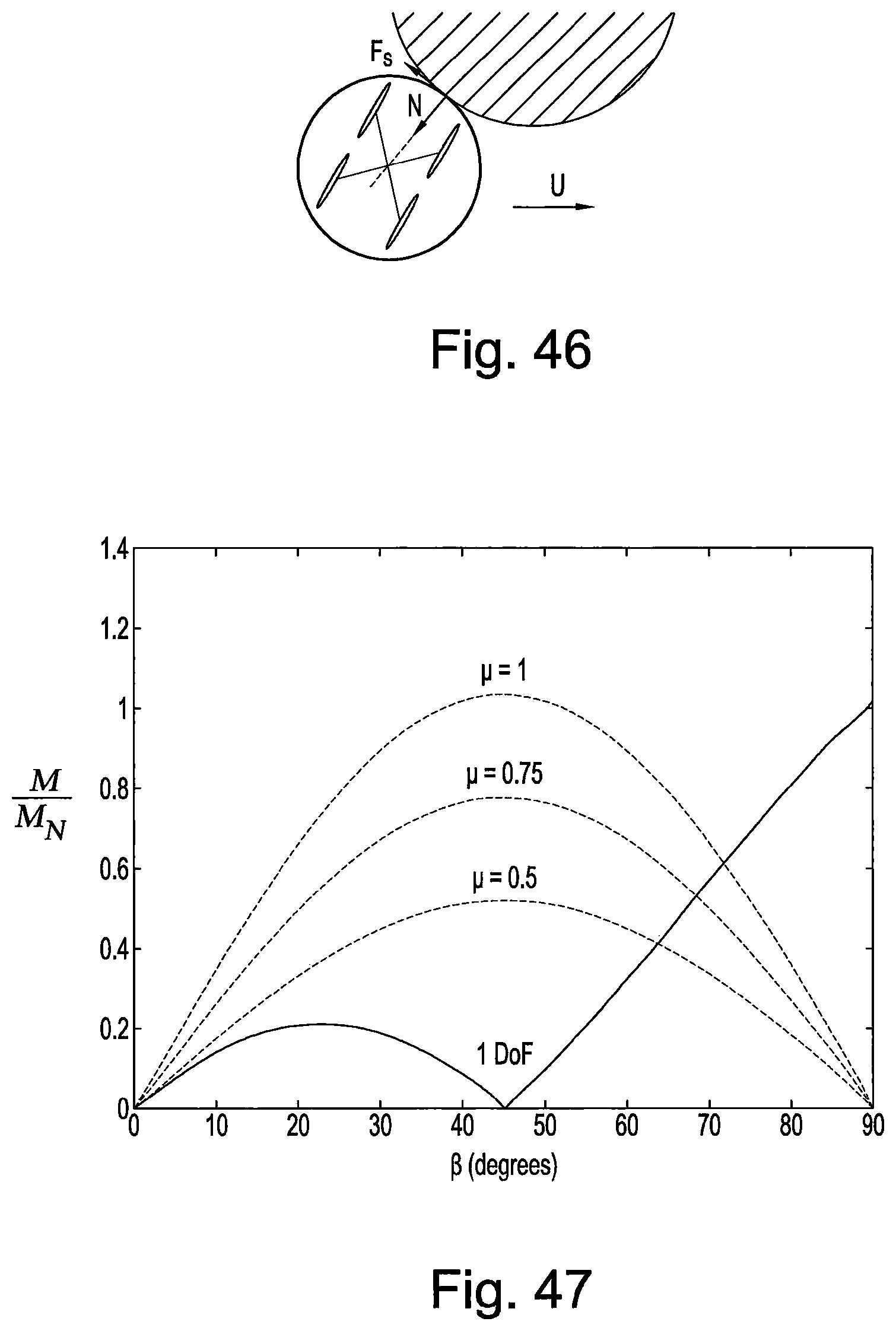
D00037

D00038

D00039

D00040

D00041

D00042

D00043

D00044

D00045

D00046

D00047

D00048

D00049

D00050

D00051

D00052

D00053

D00054
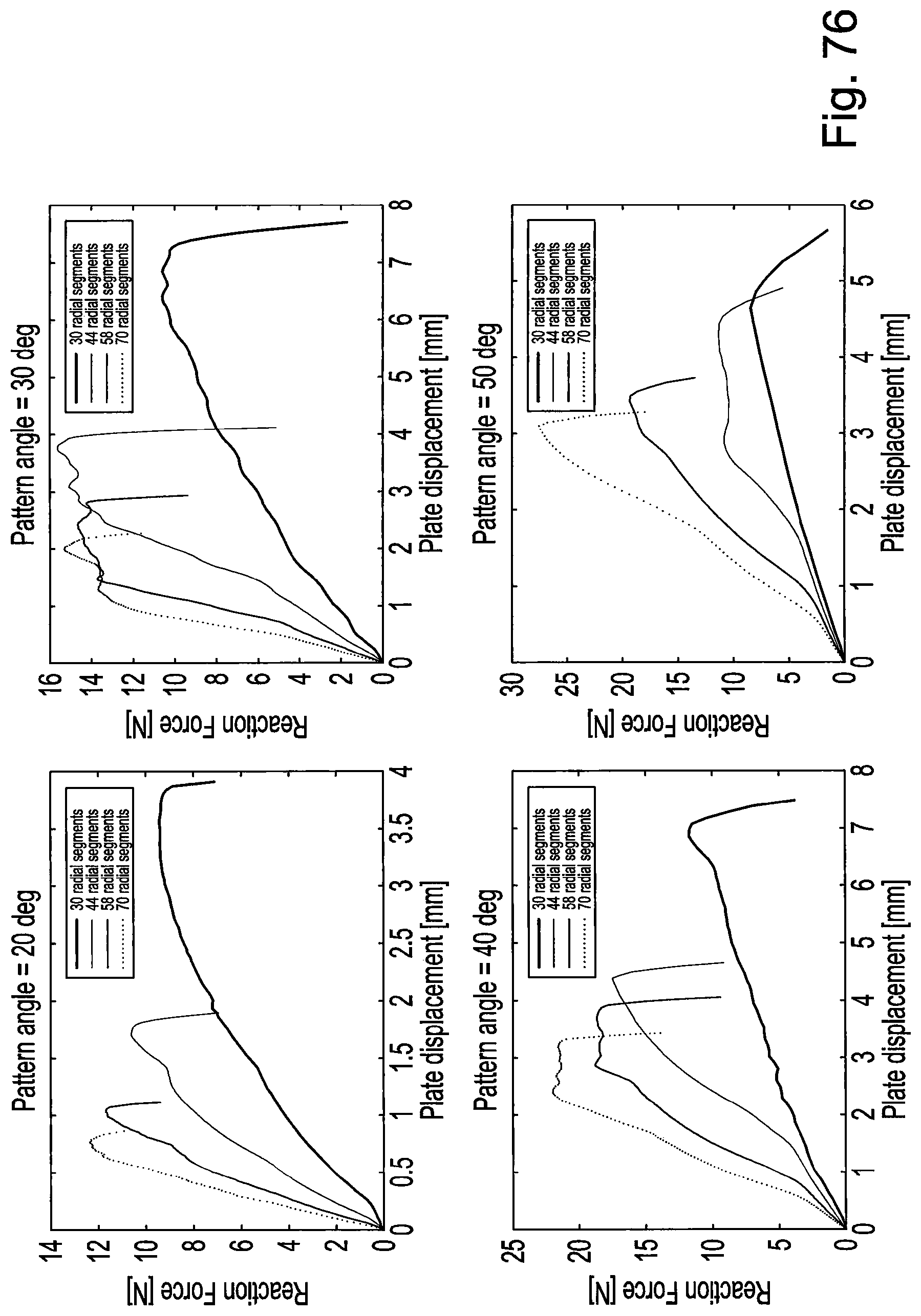
D00055

D00056

D00057

D00058

D00059

D00060

D00061

D00062

D00063

D00064

D00065

D00066

D00067

D00068

D00069

M00001

M00002

M00003

M00004

M00005

M00006

M00007

M00008

M00009

M00010

P00001

P00002

P00003

P00004
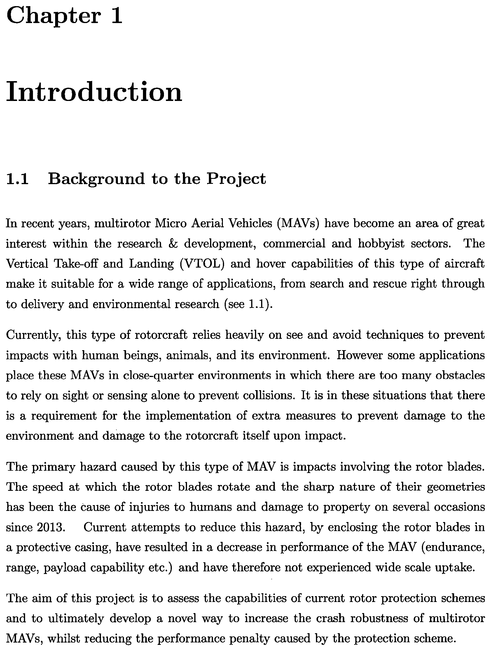
P00005
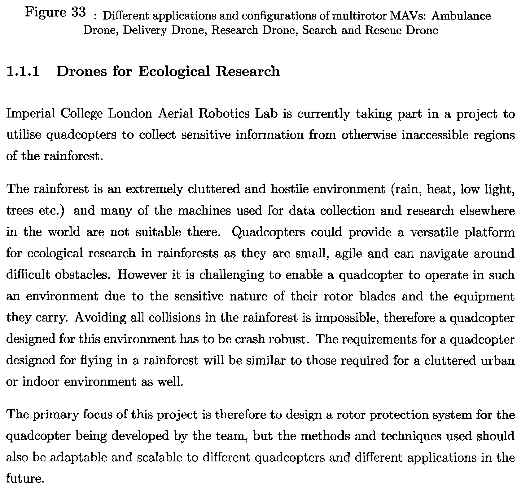
P00006

P00007

P00008
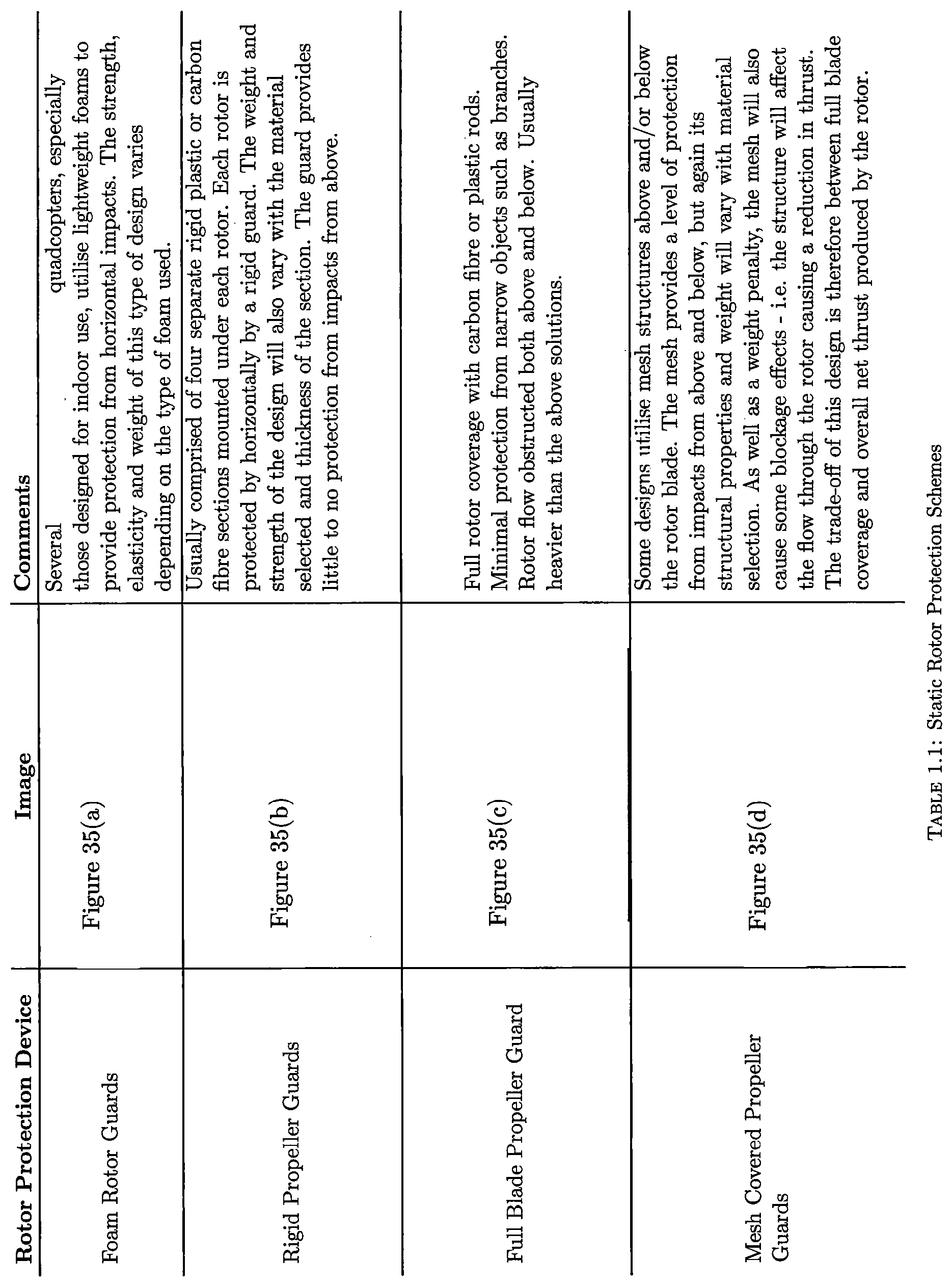
P00009

P00010
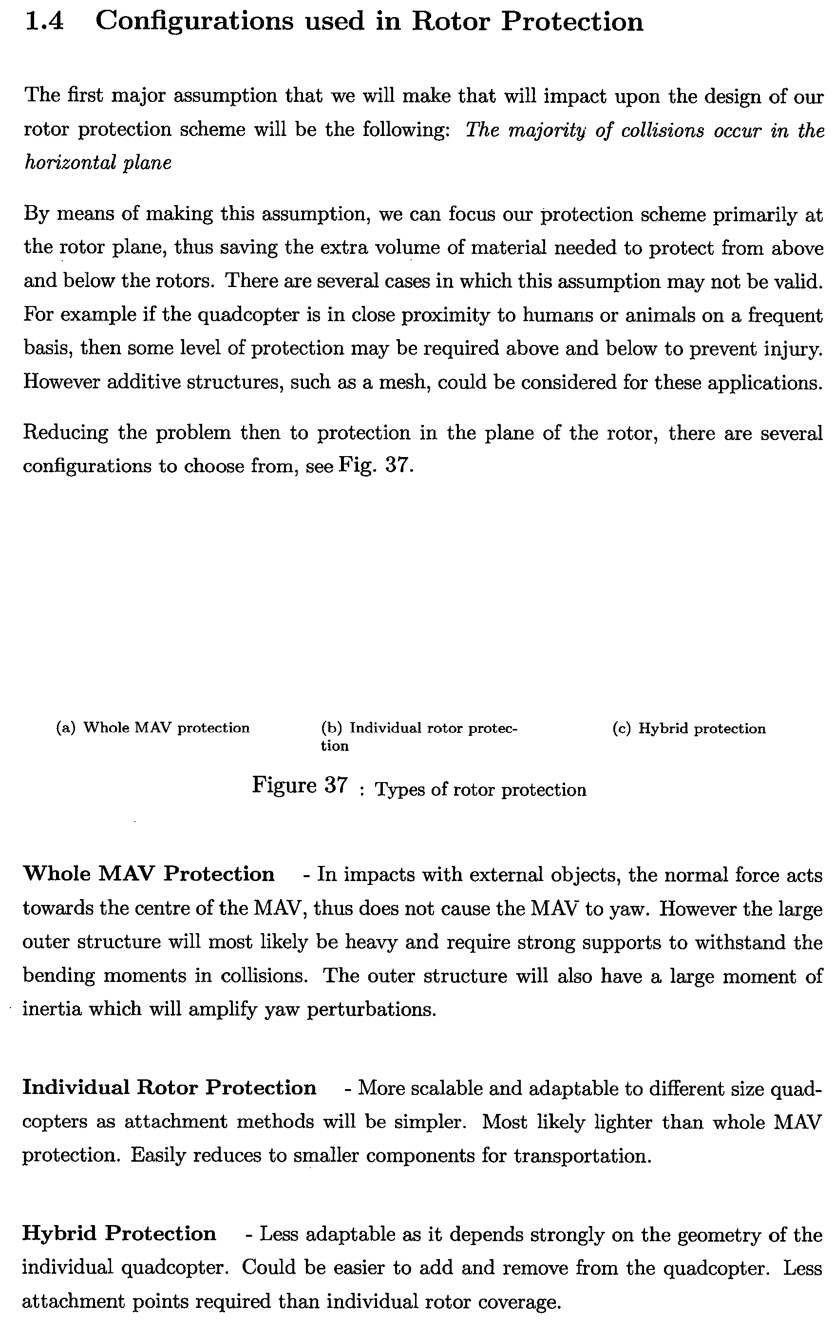
P00011

P00012

P00013

P00014

P00015

P00016

P00017

P00018

P00019

P00020

P00021

P00022

P00023

P00024

P00025

P00026

P00027

P00028

P00029
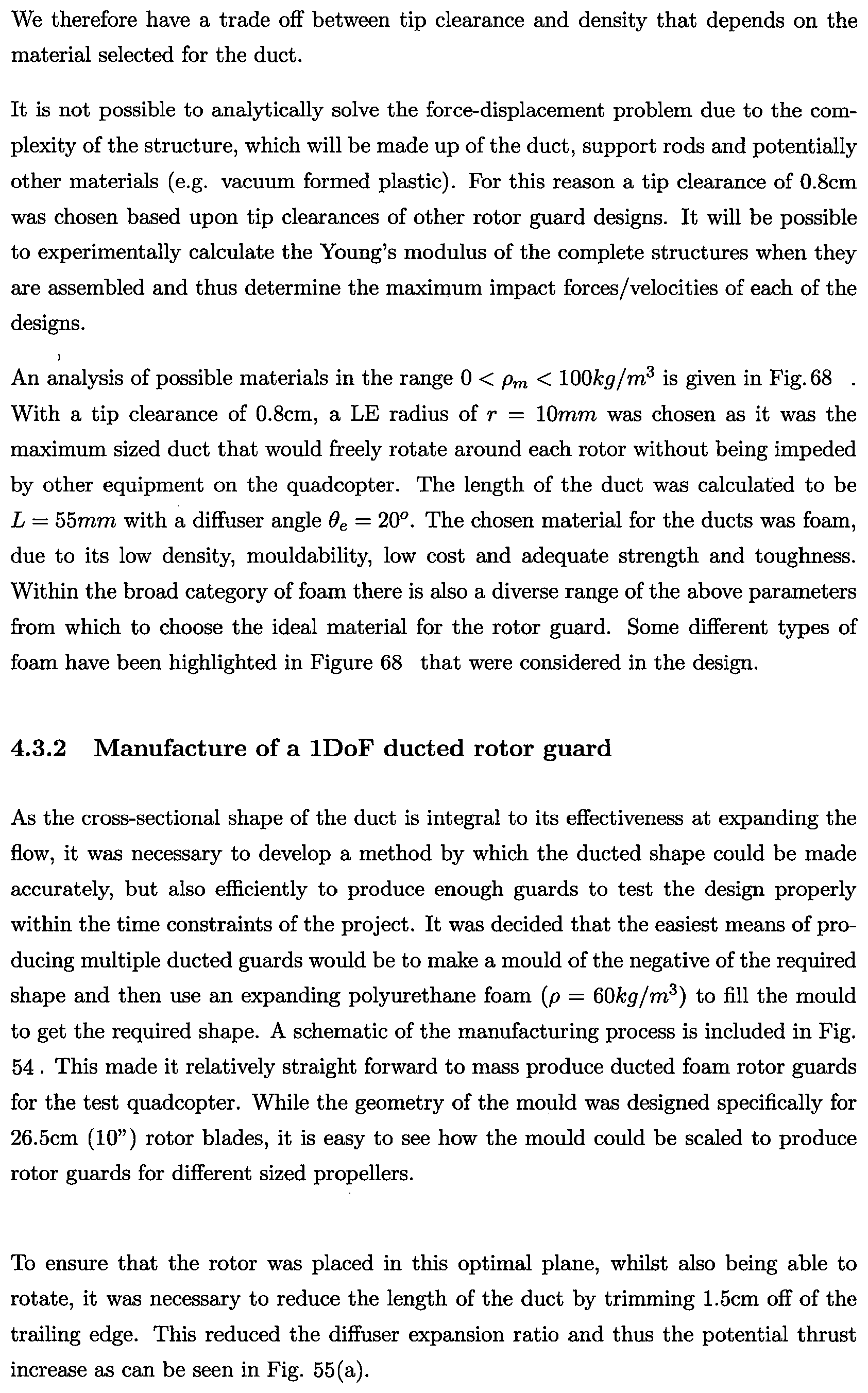
P00030

P00031

P00032

P00033
P00034

P00035

P00036

P00037
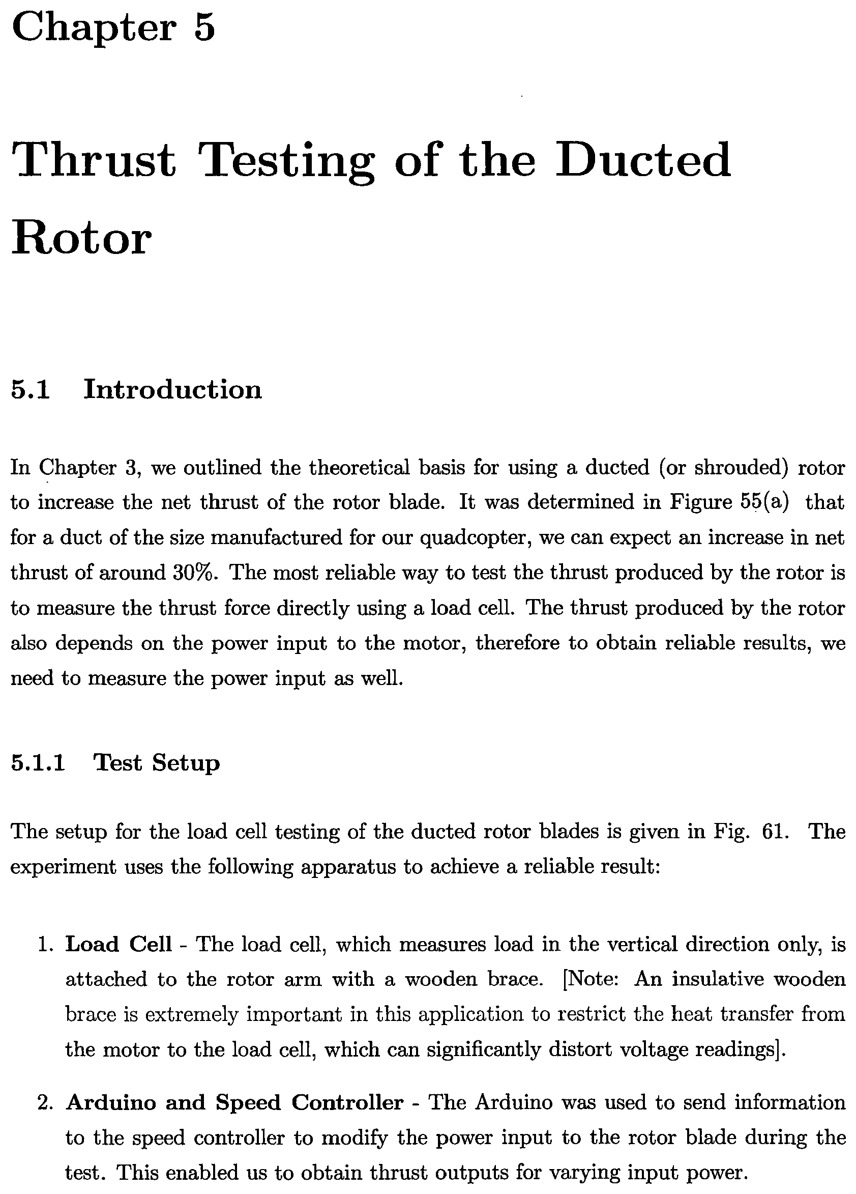
P00038
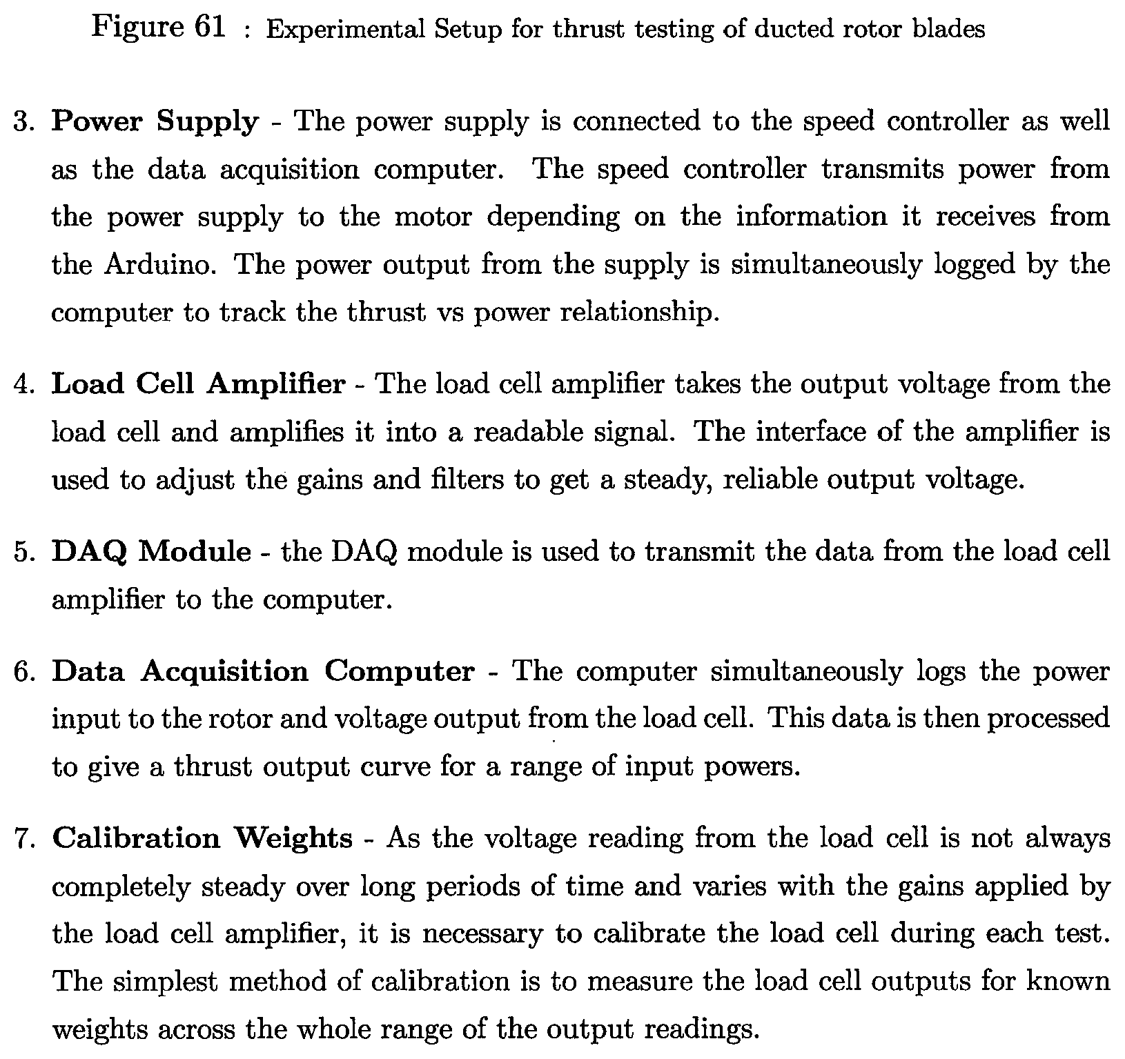
P00039

P00040

P00041

P00042

P00043
P00044
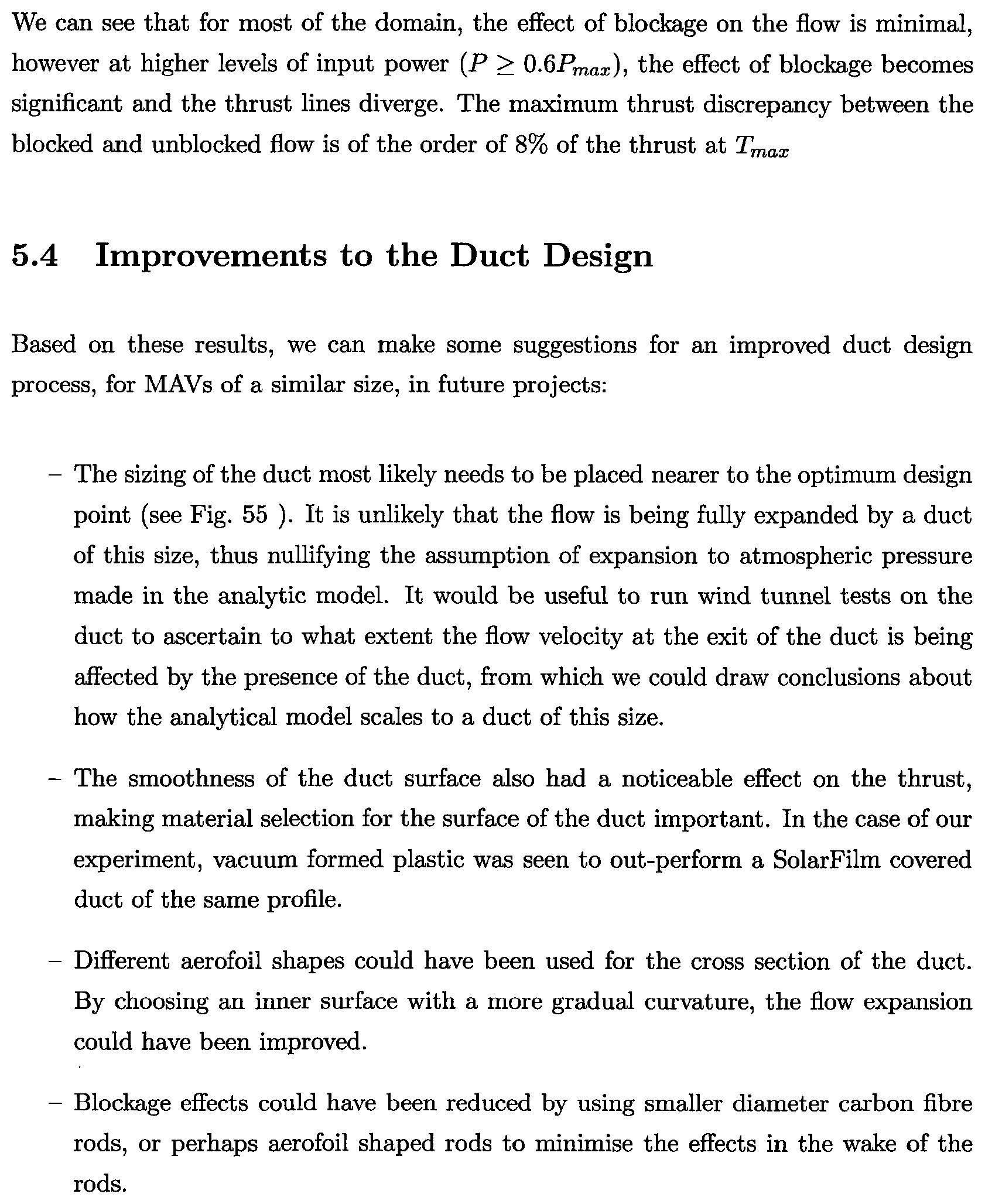
P00045

P00046

P00047

P00048
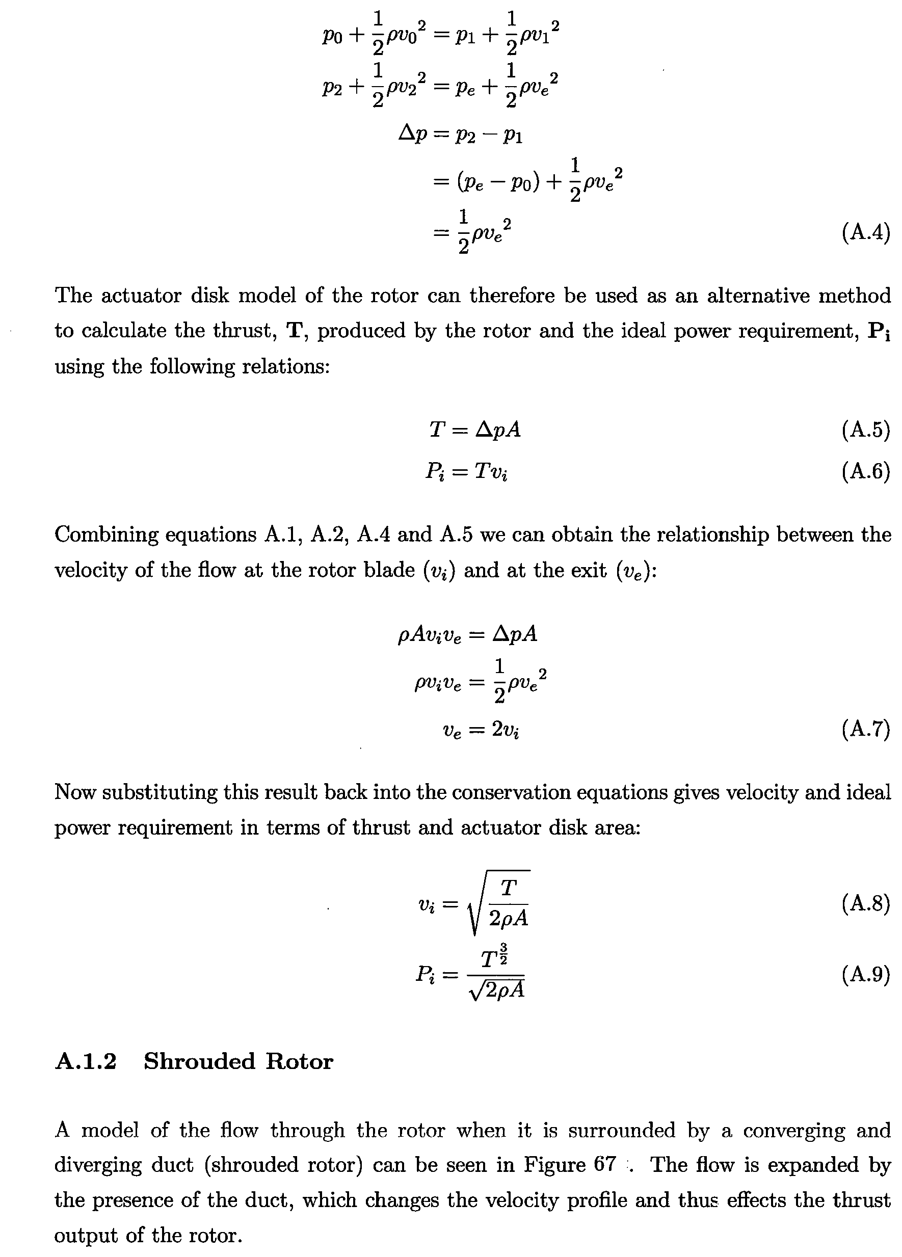
P00049

P00050
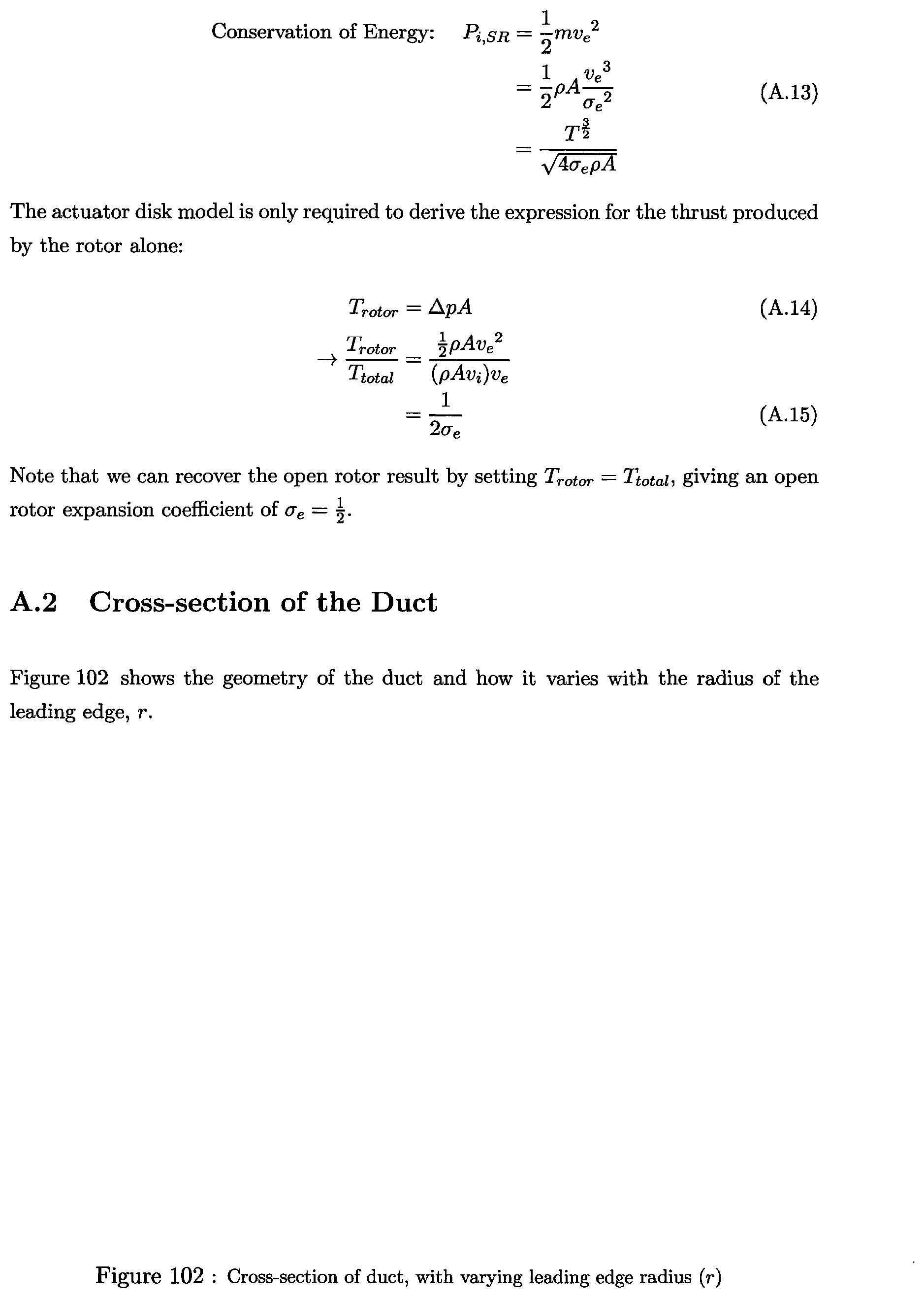
P00051

P00052

P00053

P00054

P00055

P00056

P00057

P00058

P00059

P00060

P00061
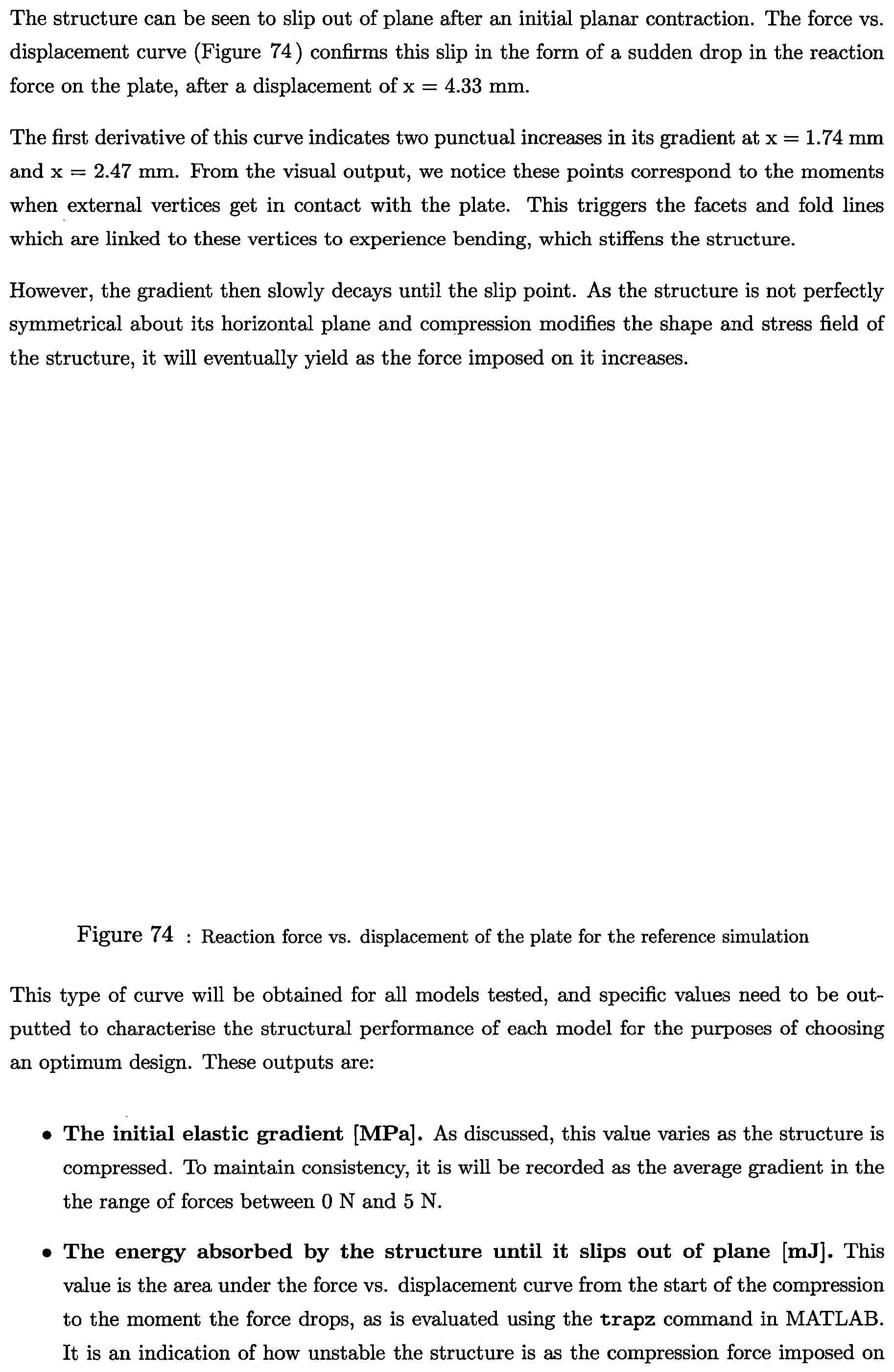
P00062

P00063

P00064

P00065

P00066

P00067

P00068

P00069

P00070

P00071

P00072

P00073

P00074

P00075

P00076

P00077

P00078

P00079

XML
uspto.report is an independent third-party trademark research tool that is not affiliated, endorsed, or sponsored by the United States Patent and Trademark Office (USPTO) or any other governmental organization. The information provided by uspto.report is based on publicly available data at the time of writing and is intended for informational purposes only.
While we strive to provide accurate and up-to-date information, we do not guarantee the accuracy, completeness, reliability, or suitability of the information displayed on this site. The use of this site is at your own risk. Any reliance you place on such information is therefore strictly at your own risk.
All official trademark data, including owner information, should be verified by visiting the official USPTO website at www.uspto.gov. This site is not intended to replace professional legal advice and should not be used as a substitute for consulting with a legal professional who is knowledgeable about trademark law.