Circular stapler with visual indicator mechanism
Zhang December 29, 2
U.S. patent number 10,874,399 [Application Number 16/073,354] was granted by the patent office on 2020-12-29 for circular stapler with visual indicator mechanism. This patent grant is currently assigned to Covidien LP. The grantee listed for this patent is Covidien LP. Invention is credited to Xiliang Zhang.


| United States Patent | 10,874,399 |
| Zhang | December 29, 2020 |
Circular stapler with visual indicator mechanism
Abstract
A surgical stapling device includes a visual indicator mechanism that provides a clinician with greater visualization of the movement of an anvil assembly in relation to a cartridge assembly after the anvil and cartridge assemblies have been approximated to within a firing zone. The visual indicator mechanism improves visualization of the different degrees of approximation within the firing zone by providing an indicator cover having spaced slots that allow indicia formed on an indicator member to sequentially appear within the spaced slots to identify the different degrees of approximation within the firing zone.
| Inventors: | Zhang; Xiliang (Shanghai, CN) | ||||||||||
|---|---|---|---|---|---|---|---|---|---|---|---|
| Applicant: |
|
||||||||||
| Assignee: | Covidien LP (Mansfield,
MA) |
||||||||||
| Family ID: | 1000005266710 | ||||||||||
| Appl. No.: | 16/073,354 | ||||||||||
| Filed: | February 4, 2016 | ||||||||||
| PCT Filed: | February 04, 2016 | ||||||||||
| PCT No.: | PCT/CN2016/073471 | ||||||||||
| 371(c)(1),(2),(4) Date: | July 27, 2018 | ||||||||||
| PCT Pub. No.: | WO2017/132932 | ||||||||||
| PCT Pub. Date: | August 10, 2017 |
Prior Publication Data
| Document Identifier | Publication Date | |
|---|---|---|
| US 20190038292 A1 | Feb 7, 2019 | |
| Current U.S. Class: | 1/1 |
| Current CPC Class: | A61B 17/072 (20130101); A61B 17/1155 (20130101); A61B 2017/07257 (20130101); A61B 2090/0811 (20160201) |
| Current International Class: | A61B 17/115 (20060101); A61B 17/072 (20060101); A61B 90/00 (20160101) |
| Field of Search: | ;227/175.1-182.1 |
References Cited [Referenced By]
U.S. Patent Documents
| 3193165 | July 1965 | Akhalaya et al. |
| 3388847 | June 1968 | Kasulin et al. |
| 3552626 | January 1971 | Astafiev et al. |
| 3638652 | February 1972 | Kelley |
| 3771526 | November 1973 | Rudie |
| 4198982 | April 1980 | Fortner et al. |
| 4207898 | June 1980 | Becht |
| 4289133 | September 1981 | Rothfuss |
| 4304236 | December 1981 | Conta et al. |
| 4319576 | March 1982 | Rothfuss |
| 4350160 | September 1982 | Kolesov et al. |
| 4351466 | September 1982 | Noiles |
| 4379457 | April 1983 | Gravener et al. |
| 4473077 | September 1984 | Noiles et al. |
| 4476863 | October 1984 | Kanshin et al. |
| 4485817 | December 1984 | Swiggett |
| 4488523 | December 1984 | Shichman |
| 4505272 | March 1985 | Utyamyshev et al. |
| 4505414 | March 1985 | Filipi |
| 4520817 | June 1985 | Green |
| 4527724 | July 1985 | Chow |
| 4550870 | November 1985 | Krumme et al. |
| 4573468 | March 1986 | Conta et al. |
| 4576167 | March 1986 | Noiles |
| 4592354 | June 1986 | Rothfuss |
| 4603693 | August 1986 | Conta et al. |
| 4606343 | August 1986 | Conta et al. |
| 4632290 | December 1986 | Green et al. |
| 4646745 | March 1987 | Noiles |
| 4665917 | May 1987 | Clanton et al. |
| 4667673 | May 1987 | Li |
| 4671445 | June 1987 | Barker et al. |
| 4700703 | October 1987 | Resnick et al. |
| 4703887 | November 1987 | Clanton et al. |
| 4708141 | November 1987 | Inoue et al. |
| 4717063 | January 1988 | Ebihara |
| 4752024 | June 1988 | Green et al. |
| 4754909 | July 1988 | Barker et al. |
| 4776506 | October 1988 | Green |
| 4817847 | April 1989 | Redtenbacher et al. |
| 4873977 | October 1989 | Avant et al. |
| 4893662 | January 1990 | Gervasi |
| 4903697 | February 1990 | Resnick et al. |
| 4907591 | March 1990 | Vasconcellos et al. |
| 4917114 | April 1990 | Green et al. |
| 4957499 | September 1990 | Lipatov et al. |
| 4962877 | October 1990 | Hervas |
| 5005749 | April 1991 | Aranyi |
| 5042707 | August 1991 | Taheri |
| 5047039 | September 1991 | Avant et al. |
| 5104025 | April 1992 | Main et al. |
| 5119983 | June 1992 | Green et al. |
| 5122156 | June 1992 | Granger et al. |
| 5139513 | August 1992 | Segato |
| 5158222 | October 1992 | Green et al. |
| 5188638 | February 1993 | Tzakis |
| 5193731 | March 1993 | Aranyi |
| 5197648 | March 1993 | Gingold |
| 5197649 | March 1993 | Bessler et al. |
| 5205459 | April 1993 | Brinkerhoff et al. |
| 5221036 | June 1993 | Takase |
| 5222963 | June 1993 | Brinkerhoff et al. |
| 5253793 | October 1993 | Green et al. |
| 5261920 | November 1993 | Main et al. |
| 5271543 | December 1993 | Grant et al. |
| 5271544 | December 1993 | Fox et al. |
| 5275322 | January 1994 | Brinkerhoff et al. |
| 5282810 | February 1994 | Allen et al. |
| 5285944 | February 1994 | Green et al. |
| 5285945 | February 1994 | Brinkerhoff et al. |
| 5292053 | March 1994 | Bilotti et al. |
| 5309927 | May 1994 | Welch |
| 5312024 | May 1994 | Grant et al. |
| 5314435 | May 1994 | Green et al. |
| 5314436 | May 1994 | Wilk |
| 5330486 | July 1994 | Wilk |
| 5333773 | August 1994 | Main et al. |
| 5344059 | September 1994 | Green et al. |
| 5346115 | September 1994 | Perouse et al. |
| 5348259 | September 1994 | Blanco et al. |
| 5350104 | September 1994 | Main et al. |
| 5355897 | October 1994 | Pietrafitta et al. |
| 5360154 | November 1994 | Green |
| 5368215 | November 1994 | Green et al. |
| 5392979 | February 1995 | Green et al. |
| 5395030 | March 1995 | Kuramoto et al. |
| 5403333 | April 1995 | Kaster et al. |
| 5404870 | April 1995 | Brinkerhoff et al. |
| 5411508 | May 1995 | Bessler et al. |
| 5425738 | June 1995 | Gustafson et al. |
| 5433721 | July 1995 | Hooven et al. |
| 5437684 | August 1995 | Calabrese et al. |
| 5439156 | August 1995 | Grant et al. |
| 5441191 | August 1995 | Linden |
| 5443198 | August 1995 | Viola et al. |
| 5447514 | September 1995 | Gerry et al. |
| 5454825 | October 1995 | Van Leeuwen et al. |
| 5464415 | November 1995 | Chen |
| 5470006 | November 1995 | Rodak |
| 5474223 | December 1995 | Viola et al. |
| 5478003 | December 1995 | Green |
| 5497934 | March 1996 | Brady et al. |
| 5503635 | April 1996 | Sauer et al. |
| 5507425 | April 1996 | Ziglioli |
| 5522534 | June 1996 | Viola et al. |
| 5533661 | July 1996 | Main et al. |
| 5588579 | December 1996 | Schnut et al. |
| 5609285 | March 1997 | Grant et al. |
| 5626591 | May 1997 | Kockerling et al. |
| 5632433 | May 1997 | Grant et al. |
| 5639008 | June 1997 | Gallagher et al. |
| 5641111 | June 1997 | Ahrens et al. |
| 5658300 | August 1997 | Bito et al. |
| 5669918 | September 1997 | Balazs et al. |
| 5685474 | November 1997 | Seeber |
| 5709335 | January 1998 | Heck |
| 5715987 | February 1998 | Kelley et al. |
| 5718360 | February 1998 | Green et al. |
| 5720755 | February 1998 | Dakov |
| 5732872 | March 1998 | Bolduc et al. |
| 5749896 | May 1998 | Cook |
| 5758814 | June 1998 | Gallagher et al. |
| 5799857 | September 1998 | Robertson et al. |
| 5814055 | September 1998 | Knodel et al. |
| 5833698 | November 1998 | Hinchliffe et al. |
| 5836503 | November 1998 | Ehrenfels et al. |
| 5839639 | November 1998 | Sauer et al. |
| 5855312 | January 1999 | Toledano |
| 5860581 | January 1999 | Robertson et al. |
| 5868760 | February 1999 | McGuckin, Jr. |
| 5881943 | March 1999 | Heck et al. |
| 5915616 | June 1999 | Viola et al. |
| 5947363 | September 1999 | Bolduc et al. |
| 5951576 | September 1999 | Wakabayashi |
| 5957363 | September 1999 | Heck |
| 5993468 | November 1999 | Rygaard |
| 6024748 | February 2000 | Manzo et al. |
| 6050472 | April 2000 | Shibata |
| 6053390 | April 2000 | Green et al. |
| 6068636 | May 2000 | Chen |
| 6083241 | July 2000 | Longo et al. |
| 6102271 | August 2000 | Longo et al. |
| 6117148 | September 2000 | Ravo et al. |
| 6119913 | September 2000 | Adams et al. |
| 6126058 | October 2000 | Adams et al. |
| 6142933 | November 2000 | Longo et al. |
| 6149667 | November 2000 | Hovland et al. |
| 6176413 | January 2001 | Heck et al. |
| 6179195 | January 2001 | Adams et al. |
| 6193129 | February 2001 | Bittner et al. |
| 6203553 | March 2001 | Robertson et al. |
| 6209773 | April 2001 | Bolduc et al. |
| 6241140 | June 2001 | Adams et al. |
| 6253984 | July 2001 | Heck et al. |
| 6258107 | July 2001 | Balazs et al. |
| 6264086 | July 2001 | McGuckin, Jr. |
| 6269997 | August 2001 | Balazs et al. |
| 6273897 | August 2001 | Dalessandro et al. |
| 6279809 | August 2001 | Nicolo |
| 6302311 | October 2001 | Adams et al. |
| 6338737 | January 2002 | Toledano |
| 6343731 | February 2002 | Adams et al. |
| 6387105 | May 2002 | Gifford, III et al. |
| 6398795 | June 2002 | McAlister et al. |
| 6402008 | June 2002 | Lucas |
| 6439446 | August 2002 | Perry et al. |
| 6443973 | September 2002 | Whitman |
| 6450390 | September 2002 | Heck et al. |
| 6478210 | November 2002 | Adams et al. |
| 6488197 | December 2002 | Whitman |
| 6491201 | December 2002 | Whitman |
| 6494877 | December 2002 | Odell et al. |
| 6503259 | January 2003 | Huxel et al. |
| 6517566 | February 2003 | Hovland et al. |
| 6520398 | February 2003 | Nicolo |
| 6533157 | March 2003 | Whitman |
| 6551334 | April 2003 | Blatter et al. |
| 6578751 | June 2003 | Hartwick |
| 6585144 | July 2003 | Adams et al. |
| 6588643 | July 2003 | Bolduc et al. |
| 6592596 | July 2003 | Geitz |
| 6601749 | August 2003 | Sullivan et al. |
| 6605078 | August 2003 | Adams |
| 6605098 | August 2003 | Nobis et al. |
| 6626921 | September 2003 | Blatter et al. |
| 6629630 | October 2003 | Adams |
| 6631837 | October 2003 | Heck |
| 6632227 | October 2003 | Adams |
| 6632237 | October 2003 | Ben-David et al. |
| 6652542 | November 2003 | Blatter et al. |
| 6659327 | December 2003 | Heck et al. |
| 6676671 | January 2004 | Robertson et al. |
| 6681979 | January 2004 | Whitman |
| 6685079 | February 2004 | Sharma et al. |
| 6695198 | February 2004 | Adams et al. |
| 6695199 | February 2004 | Whitman |
| 6698643 | March 2004 | Whitman |
| 6716222 | April 2004 | McAlister et al. |
| 6716233 | April 2004 | Whitman |
| 6726697 | April 2004 | Nicholas et al. |
| 6742692 | June 2004 | Hartwick |
| 6743244 | June 2004 | Blatter et al. |
| 6763993 | July 2004 | Bolduc et al. |
| 6769590 | August 2004 | Vresh et al. |
| 6769594 | August 2004 | Orban, III |
| 6820791 | November 2004 | Adams |
| 6821282 | November 2004 | Perry et al. |
| 6827246 | December 2004 | Sullivan et al. |
| 6840423 | January 2005 | Adams et al. |
| 6843403 | January 2005 | Whitman |
| 6846308 | January 2005 | Whitman et al. |
| 6852122 | February 2005 | Rush |
| 6866178 | March 2005 | Adams et al. |
| 6872214 | March 2005 | Sonnenschein et al. |
| 6874669 | April 2005 | Adams et al. |
| 6884250 | April 2005 | Monassevitch et al. |
| 6905504 | June 2005 | Vargas |
| 6938814 | September 2005 | Sharma et al. |
| 6942675 | September 2005 | Vargas |
| 6945444 | September 2005 | Gresham et al. |
| 6953138 | October 2005 | Dworak et al. |
| 6957758 | October 2005 | Aranyi |
| 6959851 | November 2005 | Heinrich |
| 6978922 | December 2005 | Bilotti et al. |
| 6981941 | January 2006 | Whitman et al. |
| 6981979 | January 2006 | Nicolo |
| 7032798 | April 2006 | Whitman et al. |
| 7059331 | June 2006 | Adams et al. |
| 7059510 | June 2006 | Orban, III |
| 7077856 | July 2006 | Whitman |
| 7080769 | July 2006 | Vresh et al. |
| 7086267 | August 2006 | Dworak et al. |
| 7114642 | October 2006 | Whitman |
| 7118528 | October 2006 | Piskun |
| 7122044 | October 2006 | Bolduc et al. |
| 7128748 | October 2006 | Mooradian et al. |
| 7141055 | November 2006 | Abrams et al. |
| 7168604 | January 2007 | Milliman et al. |
| 7179267 | February 2007 | Nolan et al. |
| 7182239 | February 2007 | Myers |
| 7195142 | March 2007 | Orban, III |
| 7207168 | April 2007 | Doepker et al. |
| 7220237 | May 2007 | Gannoe et al. |
| 7234624 | June 2007 | Gresham et al. |
| 7235089 | June 2007 | McGuckin, Jr. |
| RE39841 | September 2007 | Bilotti et al. |
| 7285125 | October 2007 | Viola |
| 7303106 | December 2007 | Milliman et al. |
| 7303107 | December 2007 | Milliman et al. |
| 7309341 | December 2007 | Ortiz et al. |
| 7322994 | January 2008 | Nicholas et al. |
| 7325713 | February 2008 | Aranyi |
| 7334718 | February 2008 | McAlister et al. |
| 7335212 | February 2008 | Edoga et al. |
| 7364060 | April 2008 | Milliman |
| 7398908 | July 2008 | Holsten et al. |
| 7399305 | July 2008 | Csiky et al. |
| 7401721 | July 2008 | Holsten et al. |
| 7401722 | July 2008 | Hur |
| 7407075 | August 2008 | Holsten et al. |
| 7410086 | August 2008 | Ortiz et al. |
| 7422137 | September 2008 | Manzo |
| 7422138 | September 2008 | Bilotti et al. |
| 7431191 | October 2008 | Milliman |
| 7438718 | October 2008 | Milliman et al. |
| 7455676 | November 2008 | Holsten et al. |
| 7455682 | November 2008 | Viola |
| 7464847 | December 2008 | Viola |
| 7481347 | January 2009 | Roy |
| 7494038 | February 2009 | Milliman |
| 7506791 | March 2009 | Omaits et al. |
| 7516877 | April 2009 | Aranyi |
| 7527185 | May 2009 | Harari et al. |
| 7537602 | May 2009 | Whitman |
| 7540839 | June 2009 | Butler et al. |
| 7546939 | June 2009 | Adams et al. |
| 7546940 | June 2009 | Milliman et al. |
| 7547312 | June 2009 | Bauman et al. |
| 7556186 | July 2009 | Milliman |
| 7559451 | July 2009 | Sharma |
| 7585306 | September 2009 | Abbott et al. |
| 7588174 | September 2009 | Holsten et al. |
| 7600663 | October 2009 | Green |
| 7611038 | November 2009 | Racenet et al. |
| 7635385 | December 2009 | Milliman et al. |
| 7669747 | March 2010 | Weisenburgh, II et al. |
| 7686201 | March 2010 | Csiky |
| 7694864 | April 2010 | Okada et al. |
| 7699204 | April 2010 | Viola |
| 7708181 | May 2010 | Cole et al. |
| 7717313 | May 2010 | Criscuolo et al. |
| 7721932 | May 2010 | Cole et al. |
| 7726539 | June 2010 | Holsten et al. |
| 7743958 | June 2010 | Orban, III |
| 7744627 | June 2010 | Orban, III et al. |
| 7770776 | August 2010 | Chen et al. |
| 7771440 | August 2010 | Ortiz et al. |
| 7776060 | August 2010 | Mooradian et al. |
| 7793813 | September 2010 | Bettuchi |
| 7802712 | September 2010 | Milliman et al. |
| 7823592 | November 2010 | Bettuchi et al. |
| 7837079 | November 2010 | Holsten et al. |
| 7837080 | November 2010 | Schwemberger |
| 7837081 | November 2010 | Holsten et al. |
| 7845536 | December 2010 | Viola et al. |
| 7845538 | December 2010 | Whitman |
| 7857187 | December 2010 | Milliman |
| 7886951 | February 2011 | Hessler |
| 7896215 | March 2011 | Adams et al. |
| 7900806 | March 2011 | Chen et al. |
| 7909039 | March 2011 | Hur |
| 7909219 | March 2011 | Cole et al. |
| 7909222 | March 2011 | Cole et al. |
| 7909223 | March 2011 | Cole et al. |
| 7913892 | March 2011 | Cole et al. |
| 7918377 | April 2011 | Measamer et al. |
| 7922062 | April 2011 | Cole et al. |
| 7922743 | April 2011 | Heinrich et al. |
| 7931183 | April 2011 | Orban, III |
| 7938307 | May 2011 | Bettuchi |
| 7942302 | May 2011 | Roby et al. |
| 7951166 | May 2011 | Orban, III et al. |
| 7959050 | June 2011 | Smith et al. |
| 7967181 | June 2011 | Viola et al. |
| 7975895 | July 2011 | Milliman |
| 8002795 | August 2011 | Beetel |
| 8006701 | August 2011 | Bilotti et al. |
| 8006889 | August 2011 | Adams et al. |
| 8011551 | September 2011 | Marczyk et al. |
| 8011554 | September 2011 | Milliman |
| 8016177 | September 2011 | Bettuchi et al. |
| 8016858 | September 2011 | Whitman |
| 8020741 | September 2011 | Cole et al. |
| 8025199 | September 2011 | Whitman et al. |
| 8028885 | October 2011 | Smith et al. |
| 8038046 | October 2011 | Smith et al. |
| 8043207 | October 2011 | Adams |
| 8066167 | November 2011 | Measamer et al. |
| 8066169 | November 2011 | Viola |
| 8070035 | December 2011 | Holsten et al. |
| 8070037 | December 2011 | Csiky |
| 8096458 | January 2012 | Hessler |
| 8109426 | February 2012 | Milliman et al. |
| 8109427 | February 2012 | Orban, III |
| 8113405 | February 2012 | Milliman |
| 8113406 | February 2012 | Holsten et al. |
| 8113407 | February 2012 | Holsten et al. |
| 8123103 | February 2012 | Milliman |
| 8128645 | March 2012 | Sonnenschein et al. |
| 8132703 | March 2012 | Milliman et al. |
| 8136712 | March 2012 | Zingman |
| 8146790 | April 2012 | Milliman |
| 8146791 | April 2012 | Bettuchi et al. |
| 8157145 | April 2012 | Shelton, IV et al. |
| 8181838 | May 2012 | Milliman et al. |
| 8192460 | June 2012 | Orban, III et al. |
| 8201720 | June 2012 | Hessler |
| 8203782 | June 2012 | Brueck et al. |
| 8211130 | July 2012 | Viola |
| 8225799 | July 2012 | Bettuchi |
| 8225981 | July 2012 | Criscuolo et al. |
| 8231041 | July 2012 | Marczyk et al. |
| 8231042 | July 2012 | Hessler et al. |
| 8257391 | September 2012 | Orban, III et al. |
| 8267301 | September 2012 | Milliman et al. |
| 8272552 | September 2012 | Holsten et al. |
| 8276802 | October 2012 | Kostrzewski |
| 8281975 | October 2012 | Criscuolo et al. |
| 8286845 | October 2012 | Perry et al. |
| 8308045 | November 2012 | Bettuchi et al. |
| 8312885 | November 2012 | Bettuchi et al. |
| 8313014 | November 2012 | Bettuchi |
| 8317073 | November 2012 | Milliman et al. |
| 8317074 | November 2012 | Ortiz et al. |
| 8322590 | December 2012 | Patel et al. |
| 8328060 | December 2012 | Jankowski et al. |
| 8328062 | December 2012 | Viola |
| 8328063 | December 2012 | Milliman et al. |
| 8343185 | January 2013 | Milliman et al. |
| 8353438 | January 2013 | Baxter, III et al. |
| 8353439 | January 2013 | Baxter, III et al. |
| 8353930 | January 2013 | Heinrich et al. |
| 8360295 | January 2013 | Milliman et al. |
| 8365974 | February 2013 | Milliman |
| 8403942 | March 2013 | Milliman et al. |
| 8408441 | April 2013 | Wenchell et al. |
| 8413870 | April 2013 | Pastorelli et al. |
| 8413872 | April 2013 | Patel |
| 8418905 | April 2013 | Milliman |
| 8418909 | April 2013 | Kostrzewski |
| 8424535 | April 2013 | Hessler et al. |
| 8424741 | April 2013 | McGuckin, Jr. et al. |
| 8430291 | April 2013 | Heinrich et al. |
| 8430292 | April 2013 | Patel et al. |
| 8453910 | June 2013 | Bettuchi et al. |
| 8453911 | June 2013 | Milliman et al. |
| 8485414 | July 2013 | Criscuolo et al. |
| 8490853 | July 2013 | Criscuolo et al. |
| 8511533 | August 2013 | Viola et al. |
| 8551138 | October 2013 | Orban, III et al. |
| 8567655 | October 2013 | Nalagatla et al. |
| 8579178 | November 2013 | Holsten et al. |
| 8590763 | November 2013 | Milliman |
| 8590764 | November 2013 | Hartwick et al. |
| 8608047 | December 2013 | Holsten et al. |
| 8616428 | December 2013 | Milliman et al. |
| 8616429 | December 2013 | Viola |
| 8622275 | January 2014 | Baxter, III et al. |
| 8631993 | January 2014 | Kostrzewski |
| 8636187 | January 2014 | Hueil et al. |
| 8640940 | February 2014 | Ohdaira |
| 8662370 | March 2014 | Takei |
| 8663258 | March 2014 | Bettuchi et al. |
| 8672931 | March 2014 | Goldboss et al. |
| 8678264 | March 2014 | Racenet et al. |
| 8684248 | April 2014 | Milliman |
| 8684250 | April 2014 | Bettuchi et al. |
| 8684251 | April 2014 | Rebuffat et al. |
| 8684252 | April 2014 | Patel et al. |
| 8714430 | May 2014 | Natarajan |
| 8733611 | May 2014 | Milliman |
| 2003/0111507 | June 2003 | Nunez |
| 2004/0073090 | April 2004 | Butler et al. |
| 2005/0023325 | February 2005 | Gresham |
| 2005/0051597 | March 2005 | Toledano |
| 2005/0107813 | May 2005 | Gilete Garcia |
| 2006/0000869 | January 2006 | Fontayne |
| 2006/0011698 | January 2006 | Okada et al. |
| 2006/0144893 | July 2006 | Lee |
| 2006/0201989 | September 2006 | Ojeda |
| 2007/0027473 | February 2007 | Vresh et al. |
| 2007/0029363 | February 2007 | Popov |
| 2007/0060952 | March 2007 | Roby et al. |
| 2008/0078808 | April 2008 | Hess |
| 2008/0300580 | December 2008 | Shelton, IV |
| 2009/0090763 | April 2009 | Zemlok |
| 2009/0236392 | September 2009 | Cole et al. |
| 2009/0236398 | September 2009 | Cole et al. |
| 2009/0236401 | September 2009 | Cole et al. |
| 2010/0019016 | January 2010 | Edoga et al. |
| 2010/0051668 | March 2010 | Milliman et al. |
| 2010/0051669 | March 2010 | Milliman |
| 2010/0069942 | March 2010 | Shelton, IV |
| 2010/0084453 | April 2010 | Hu |
| 2010/0147923 | June 2010 | D'Agostino et al. |
| 2010/0163598 | July 2010 | Belzer |
| 2010/0224668 | September 2010 | Fontayne et al. |
| 2010/0230465 | September 2010 | Smith et al. |
| 2010/0258611 | October 2010 | Smith et al. |
| 2010/0264195 | October 2010 | Bettuchi |
| 2010/0327041 | December 2010 | Milliman et al. |
| 2011/0011916 | January 2011 | Levine |
| 2011/0114697 | May 2011 | Baxter, III et al. |
| 2011/0114700 | May 2011 | Baxter, III et al. |
| 2011/0139852 | June 2011 | Zingman |
| 2011/0144640 | June 2011 | Heinrich et al. |
| 2011/0147432 | June 2011 | Heinrich et al. |
| 2011/0192882 | August 2011 | Hess et al. |
| 2012/0145755 | June 2012 | Kahn |
| 2012/0193395 | August 2012 | Pastorelli et al. |
| 2012/0193398 | August 2012 | Williams et al. |
| 2012/0232339 | September 2012 | Csiky |
| 2012/0273548 | November 2012 | Ma et al. |
| 2012/0325888 | December 2012 | Qiao et al. |
| 2013/0015232 | January 2013 | Smith et al. |
| 2013/0020372 | January 2013 | Jankowski et al. |
| 2013/0020373 | January 2013 | Smith et al. |
| 2013/0032628 | February 2013 | Li et al. |
| 2013/0056516 | March 2013 | Viola |
| 2013/0060258 | March 2013 | Giacomantonio |
| 2013/0105544 | May 2013 | Mozdzierz et al. |
| 2013/0105546 | May 2013 | Milliman et al. |
| 2013/0105551 | May 2013 | Zingman |
| 2013/0126580 | May 2013 | Smith et al. |
| 2013/0153630 | June 2013 | Miller et al. |
| 2013/0153631 | June 2013 | Vasudevan et al. |
| 2013/0153633 | June 2013 | Casasanta, Jr. et al. |
| 2013/0153634 | June 2013 | Carter et al. |
| 2013/0153638 | June 2013 | Carter et al. |
| 2013/0153639 | June 2013 | Hodgkinson et al. |
| 2013/0175315 | July 2013 | Milliman |
| 2013/0175318 | July 2013 | Felder et al. |
| 2013/0175319 | July 2013 | Felder et al. |
| 2013/0175320 | July 2013 | Mandakolathur Vasudevan et al. |
| 2013/0181035 | July 2013 | Milliman |
| 2013/0181036 | July 2013 | Olson et al. |
| 2013/0186930 | July 2013 | Wenchell et al. |
| 2013/0193185 | August 2013 | Patel |
| 2013/0193187 | August 2013 | Milliman |
| 2013/0193190 | August 2013 | Carter et al. |
| 2013/0193191 | August 2013 | Stevenson et al. |
| 2013/0193192 | August 2013 | Casasanta, Jr. et al. |
| 2013/0200131 | August 2013 | Racenet et al. |
| 2013/0206816 | August 2013 | Penna |
| 2013/0214027 | August 2013 | Hessler et al. |
| 2013/0214028 | August 2013 | Patel et al. |
| 2013/0228609 | September 2013 | Kostrzewski |
| 2013/0240597 | September 2013 | Milliman et al. |
| 2013/0240600 | September 2013 | Bettuchi |
| 2013/0248581 | September 2013 | Smith et al. |
| 2013/0277411 | October 2013 | Hodgkinson et al. |
| 2013/0277412 | October 2013 | Gresham et al. |
| 2013/0284792 | October 2013 | Ma |
| 2013/0292449 | November 2013 | Bettuchi et al. |
| 2013/0299553 | November 2013 | Mozdzierz |
| 2013/0299554 | November 2013 | Mozdzierz |
| 2013/0306701 | November 2013 | Olson |
| 2013/0306707 | November 2013 | Viola et al. |
| 2014/0008413 | January 2014 | Williams |
| 2014/0012317 | January 2014 | Orban et al. |
| 2016/0106418 | April 2016 | Shi |
| 2016/0143641 | May 2016 | Sapienza et al. |
| 2016/0157856 | June 2016 | Williams et al. |
| 2016/0174988 | June 2016 | D'Agostino et al. |
| 2016/0199089 | July 2016 | Hess |
| 2016/0302792 | October 2016 | Motai |
| 2017/0105736 | April 2017 | Chen |
| 2017/0319206 | November 2017 | Zhan |
| 2018/0028188 | February 2018 | Murugesan |
| 908529 | Aug 1972 | CA | |||
| 2805365 | Aug 2013 | CA | |||
| 1057729 | May 1959 | DE | |||
| 3301713 | Jul 1984 | DE | |||
| 0152382 | Aug 1985 | EP | |||
| 0173451 | Mar 1986 | EP | |||
| 0190022 | Aug 1986 | EP | |||
| 0282157 | Sep 1988 | EP | |||
| 0503689 | Sep 1992 | EP | |||
| 1354560 | Oct 2003 | EP | |||
| 2138118 | Dec 2009 | EP | |||
| 2168510 | Mar 2010 | EP | |||
| 2238926 | Oct 2010 | EP | |||
| 2524656 | Nov 2012 | EP | |||
| 1136020 | May 1957 | FR | |||
| 1461464 | Feb 1966 | FR | |||
| 1588250 | Apr 1970 | FR | |||
| 2443239 | Jul 1980 | FR | |||
| 1185292 | Mar 1970 | GB | |||
| 2016991 | Sep 1979 | GB | |||
| 2070499 | Sep 1981 | GB | |||
| 2004147969 | May 2004 | JP | |||
| 2010253280 | Nov 2010 | JP | |||
| 2011136169 | Jul 2011 | JP | |||
| 2013138860 | Jul 2013 | JP | |||
| 2015506223 | Mar 2015 | JP | |||
| 2015110062 | Jun 2015 | JP | |||
| 7711347 | Apr 1979 | NL | |||
| 1509052 | Sep 1989 | SU | |||
| 8706448 | Nov 1987 | WO | |||
| 8900406 | Jan 1989 | WO | |||
| 9006085 | Jun 1990 | WO | |||
| 98/35614 | Aug 1998 | WO | |||
| 0154594 | Aug 2001 | WO | |||
| 2008107918 | Sep 2008 | WO | |||
Other References
|
Japanese Office Action dated Sep. 10, 2019, issued in JP Application No. 2018-537847 (English translation not available). cited by applicant . European Search Report dated Aug. 5, 2019, issued in EP Appln. No. 16888757. cited by applicant. |
Primary Examiner: Long; Robert F
Attorney, Agent or Firm: Carter, DeLuca & Farrell LLP
Claims
What is claimed is:
1. A surgical stapling device comprising: a handle assembly including a stationary handle and a firing trigger, the stationary handle defining a window; a central body extending distally from the handle assembly; a cartridge assembly supported on a distal end of the central body; an anvil assembly; an approximation mechanism including a longitudinally movable drive screw, the drive screw being operatively connected to the anvil assembly such that longitudinal movement of the drive screw between advanced and retracted positions effects movement of the anvil assembly in relation to the cartridge assembly between spaced and approximated positions, the drive screw supporting an abutment; and a visual indicator mechanism including an indicator cover, an indicator and an indicator plate, the indicator cover being supported on the stationary handle above the window and defining a plurality of spaced slots, the indicator being positioned beneath the indicator cover adjacent the window, the indicator supporting indicia, and the indicator plate movable from an advanced position to a retracted position within the stationary handle, the indicator plate supporting a stop member and having a distal end connected to the indicator, wherein the stop member is positioned to engage the abutment such that movement of the drive screw between the advanced and retracted positions effects movement of the indicator within the indicator cover between first and second positions, wherein the indicia are dimensioned and configured such that movement of the indicator within the indicator cover as the indicator plate is moved from the advanced position to the retracted position causes the indicia to become sequentially visible within the plurality of slots such that the indicia is visible in all of the plurality of spaced slots when the indicator plate is in its retracted position, and wherein positioning of the indicia within a first slot of the plurality of slots indicates that the anvil assembly has been approximated in relation to the cartridge assembly to define a maximum tissue gap within a firing zone, positioning of the indicia within a second slot of the plurality of slots indicates that the anvil assembly has been approximated in relation to the cartridge assembly to define an intermediate tissue gap within the firing zone, and positioning of the indicia within a third slot of the plurality of slots indicates that the anvil assembly has been approximated in relation to the cartridge assembly to define a minimum tissue gap within a firing zone.
2. The surgical stapling device according to claim 1, further including a biasing member supported within the stationary handle and positioned to urge the indicator plate towards the advanced position.
3. The surgical stapling device according to claim 1, wherein the indicia include a plurality of spaced colored bands.
4. The surgical stapling device according to claim 3, wherein the plurality of spaced colored bands includes first, second, and third colored bands.
5. The surgical stapling device according to claim 4, wherein when the indicator is in the first position, the first colored band is spaced from the first slot a first distance, the second colored band is spaced from the second slot a second distance, and the third colored band is spaced from the third slot a third distance, the first distance being greater than the first and second distances and the second distance being greater than the third distance.
6. The surgical stapling device according to claim 5, wherein the first colored band has a first width, the second colored band has a second width and the third colored band has a third width, the first width being less than the second and third widths and the second width being less than the third width.
7. The surgical stapling device according to claim 1, wherein the indicator is pivotally supported beneath the indicator cover within the stationary handle.
8. The surgical stapling device according to claim 1, wherein the indicator plate includes a coupling member defining an elongated slot and the indicator includes an engagement member, the engagement member received within the elongated slot to couple the indicator to the indicator plate.
9. The surgical stapling device according to claim 1, wherein the indicator plate includes a proximally extending portion and the stationary handle includes a bracket defining a cutout, the proximally extending portion extending through the cutout to guide movement of the indicator plate within the stationary handle.
10. The surgical stapling device according to claim 9, wherein the biasing member is positioned in compression about the proximally extending portion between the bracket and a central portion of the indicator plate to urge the indicator plate in a distal direction.
11. The surgical stapling device according to claim 1, wherein the indicia include a stepped colored band.
12. The surgical stapling device according to claim 11, wherein the plurality of slots are laterally and longitudinally spaced from each other.
13. The surgical stapling device according to claim 12, wherein the stepped colored band includes first, second, and third steps.
14. The surgical stapling device according to claim 13, wherein when the indicator is in the first position, the first step of the colored band is spaced from the first slot a first distance, the second step of the colored band is spaced from the second slot a second distance, and the third step of the colored band is spaced from the third slot a third distance, the first distance being greater than the first and second distances and the second distance being greater than the third distance.
Description
CROSS-REFERENCE TO RELATED APPLICATIONS
This application is a U.S. National Stage Application filed under 35 U.S.C. .sctn. 371(a) which claims the benefit of and priority of International Patent Application Serial No. PCT/CN2016/073471, filed Feb. 4, 2016, the entire disclosure of which is incorporated by reference herein.
BACKGROUND
1.Technical Field
The present disclosure relates to surgical stapling devices, and more particularly, to circular stapling devices that include visual indicator mechanisms for indicating when the surgical stapling device is in a fire-ready zone.
2. Background of Related Art
Anastomosis is the surgical joining of separate hollow organ sections. In known circular anastomosis procedures, two ends of organ sections are joined by means of a surgical stapling device that drives a circular array of staples through each organ section and simultaneously cores any tissue interior of the driven circular array of staples to free a tubular passage. Examples of such devices are described in U.S. Pat. Nos. 7,234,624, 6,945,444, 6,053,390, 5,568,579, 5,119,983, 4,646,745, 4,576,167, and 4,473,077, the content of each of which is incorporated herein by reference in its entirety.
Typically, a circular stapling device has an elongated shaft having a handle portion supported at a proximal end of the shaft and a staple cartridge supported at a distal end of the shaft. An anvil assembly including an anvil rod and an anvil head is also mounted to the distal end of the device. The anvil head is approximated in relation to the staple cartridge to clamp tissue between the staple cartridge and the anvil head of the anvil assembly.
Known surgical stapling devices include an indicator mechanism that provides an indication to a clinician that the anvil head of the anvil assembly has been moved into a firing zone in close approximation with a staple cartridge of the cartridge assembly. The firing zone is the zone of approximation in which the anvil head is positioned in close enough approximation with the staple cartridge to facilitate the proper formation of staples. Due to the small size of the staples being fired and, thus, the limited size of the firing zone, it can be difficult for a clinician to accurately identify using known visual indicator mechanisms exactly where the anvil head is in relation to the staple cartridge in the firing zone.
It would be advantageous to provide a surgical stapling device including a visual indicator mechanism capable of accurately identifying to a clinician the location of the anvil head within the firing zone during approximation of the anvil head and the staple cartridge.
SUMMARY
The presently disclosed visual indicator mechanism and surgical stapling device including such a visual indicator mechanism is provided to afford a clinician greater visualization of the movement of an anvil assembly in relation to a cartridge assembly after the anvil and cartridge assemblies have been approximated to within a firing zone, i.e., the zone of approximation in which the anvil head and staple cartridge are in close enough approximation to allow for the proper formation of staples against the anvil assembly. The visual indicator mechanism improves visualization of the different degrees of approximation within the firing zone by providing an indicator cover having spaced slots that allow indicia formed on an indicator member to sequentially appear within the spaced slots to identify the different degrees of approximation within the firing zone. Improving visualization of the position of the anvil head in relation to the staple cartridge of the cartridge assembly during approximation of the anvil head and staple cartridge within the firing zone allows the clinician to better control the degree of approximation to compensate for different tissue thicknesses.
In one aspect of the present disclosure, a surgical stapling device includes a handle assembly having a stationary handle defining a window and a firing trigger. A central body extends distally from the handle assembly. A cartridge assembly is supported on a distal end of the central body and an anvil assembly is supported on the distal end of the stapling device. An approximation mechanism includes a longitudinally movable drive screw that is operatively connected to the anvil assembly such that longitudinal movement of the drive screw between advanced and retracted positions effects movement of the anvil assembly in relation to the cartridge assembly between spaced and approximated positions. The drive screw supports an abutment. A visual indicator mechanism includes an indicator cover, an indicator and an indicator plate. The indicator cover is supported on the stationary handle above the window and defines a plurality of spaced slots. The indicator is positioned beneath the indicator cover adjacent the window and supports indicia. An indicator plate is movable from an advanced position to a retracted position within the stationary handle. The indicator plate supports a stop member and has a distal end connected to the indicator. The stop member is positioned to engage the abutment such that movement of the drive screw between the advanced and retracted positions effects movement of the indicator within the indicator cover between first and second positions, wherein the indicia are dimensioned and configured such that movement of the indicator within the indicator cover as the indicator plate is moved from the advanced position to the retracted position causes the indicia to become sequentially visible within the plurality of slots.
In embodiments, the visual indicator mechanism includes a biasing member supported within the stationary handle and positioned to urge the indicator plate towards the advanced position.
In embodiments, the indicia include a plurality of spaced colored bands.
In some embodiments, the plurality of slots includes first, second and third slots, and the plurality of spaced colored bands includes first, second, and third colored bands.
In certain embodiments, when the indicator is in the first position, the first colored band is spaced from the first slot a first distance, the second colored band is spaced from the second slot a second distance, and the third colored band is spaced from the third slot a third distance, wherein the first distance is greater than the second and third distances and the second distance is greater than the third distance.
In embodiments, the first colored band has a first width, the second colored band has a second width and the third colored band has a third width, the first width being less than the second and third widths and the second width being less than the third width.
In some embodiments, the indicator is pivotally supported beneath the indicator cover within the stationary handle.
In certain embodiments, the indicator plate includes a coupling member defining an elongated slot and the indicator includes an engagement member, the engagement member being received within the elongated slot to couple the indicator to the indicator plate.
In embodiments, the indicator plate includes a proximally extending portion and the stationary handle includes a bracket defining a cutout. The proximally extending portion extends through the cutout to guide movement of the indicator plate within the stationary handle.
In some embodiments, the biasing member is positioned in compression about the proximally extending portion between the bracket and a central portion of the indicator plate to urge the indicator plate in a distal direction.
In certain embodiments, the indicia include a stepped colored band and the plurality of slots includes first, second and third slots that are laterally and longitudinally spaced from each other.
In embodiments, the plurality of slots includes first, second and third slots, and the stepped colored band includes first, second, and third steps.
In some embodiments, when the indicator is in the first position, the first step of the colored band is spaced from the first slot a first distance, the second step of the colored band is spaced from the second slot a second distance, and the third step of the colored band is spaced from the third slot a third distance, wherein the first distance is greater than the first and second distances and the second distance is greater than the third distance.
BRIEF DESCRIPTION OF THE DRAWINGS
Various embodiments of a surgical stapling device including the presently disclosed visual indicator mechanism are described herein below with reference to the drawings, wherein:
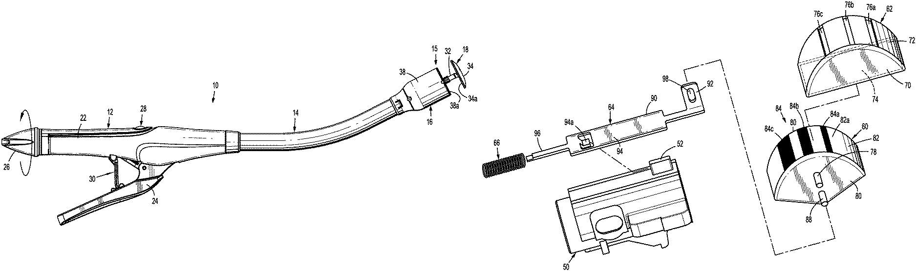
FIG. 1 is a perspective view of a surgical stapling device including one embodiment of the presently disclosed visual indicator mechanism with the end effector in an unapproximated position;
FIG. 2 is an enlarged view of the distal end of the surgical stapling device shown in FIG. 1 with the end effector in an approximated position and tissue clamped between an anvil head of the anvil assembly and the staple cartridge of a cartridge assembly;
FIG. 3 is a side view of the handle assembly of the surgical stapling device shown in FIG. 1 with a handle half-section removed illustrating the visual indicator mechanism;
FIG. 3A is a side, perspective, exploded view of the visual indicator mechanism of the surgical stapling device shown in FIG. 1;
FIG. 4 is a top view of the indicator of the visual indicator mechanism shown in FIG. 3A;
FIG. 5 is a top, cutaway view of the handle assembly of the surgical stapling device shown in FIG. 1 from above the indicator cover prior to approximation of the anvil head into the firing zone showing colored bands of the indicator in phantom;
FIG. 6 is a top, cutaway view of the handle assembly of the surgical stapling device shown in FIG. 1 from above the indicator cover with the anvil head approximated into the firing zone to a maximum tissue gap;
FIG. 7 is a top, cutaway view of the handle assembly of the surgical stapling device shown in FIG. 1 from above the indicator cover with the anvil head approximated into the firing zone to an intermediate tissue gap;
FIG. 8 is a top, cutaway view of the handle assembly of the surgical stapling device shown in FIG. 1 from above the indicator cover with the anvil head approximated into the firing zone to a minimum tissue gap;
FIG. 9 is a top view of the indicator of another embodiment of the presently disclosed visual indicator mechanism;
FIG. 10 is a top, cutaway view of the handle assembly of a surgical stapling device as shown in FIG. 1 including the visual indicator mechanism of FIG. 9 from above the indicator cover the anvil head approximated into the firing zone to a maximum tissue gap;
FIG. 11 is a top, cutaway view of the handle assembly of a surgical stapling device as shown in FIG. 1 from above the indicator cover with the anvil head approximated into the firing zone to an intermediate tissue gap; and
FIG. 8 is a top, cutaway view of the handle assembly of a surgical stapling device as shown in FIG. 1 from above the indicator cover with the anvil head approximated into the firing zone to a minimum tissue gap;
DETAILED DESCRIPTION OF EMBODIMENTS
A surgical stapling device including embodiments of the presently disclosed visual indicator mechanism will now be described in detail with reference to the drawings in which like reference numerals designate identical or corresponding elements in each of the several views. In this description, the term "proximal" is used generally to refer to the portion of the device that is closer to a clinician, while the term "distal" is used generally to refer to the portion of the device that is farther from the clinician. In addition, the term "endoscopic" is used generally to refer to procedures including endoscopic, laparoscopic, and arthroscopic performed through a small incision or a cannula inserted into a patient's body. Finally, the term clinician is used generally to refer to medical personnel including doctors, nurses, and support personnel.
The presently disclosed visual indicator mechanism is provided to afford a clinician greater visualization of the movement of an anvil assembly in relation to a cartridge assembly after the anvil and firing assemblies have been approximated to within a firing zone, i.e., the zone of approximation in which the anvil head and staple cartridge are in close enough approximation to allow for the proper formation of staples against the anvil assembly. Improving visualization of the position of the anvil head in relation to the staple cartridge of the cartridge assembly during approximation of the anvil head and staple cartridge within the firing zone allows the clinician to better control the degree of approximation to compensate for different tissue thicknesses.
FIGS. 1 and 2 illustrate one embodiment of a surgical stapling device 10 including one embodiment of the presently disclosed visual indicator mechanism as described in further detail below. Briefly, surgical stapling device 10 includes a handle assembly 12, a central body or elongated portion 14, and an end effector 15 including a shell or cartridge assembly 16 and an anvil assembly 18. Although the central body portion 14 is shown to be slightly curved, it is to be understood that the central body portion 14 can be straight or have any degree of curvature suitable to perform a desired surgical procedure.
Except where otherwise noted, the components of stapling device 10 are generally formed from thermoplastics including polycarbonates, and metals including stainless steel and aluminum. The particular material selected to form a particular component will depend upon the strength requirements of the particular component and upon whether the component is a reusable or disposable component. For example, the anvil assembly 18 may be formed from metal such as stainless steel, whereas portions of handle assembly 12 may be formed from thermoplastics such as a polycarbonate. In addition, the handle assembly 12 may be formed of an autoclavable material to allow for reuse whereas portions of the cartridge assembly may be formed of thermoplastics to allow for disposal. It is envisioned that other materials having the requisite strength requirements which are suitable for surgical use may be used to form the components of surgical stapling device 10.
Handle assembly 12 includes a stationary handle 22, a firing trigger 24, an approximation knob 26, a visual indictor mechanism or indicator assembly 28, and a lockout mechanism 30. The approximation knob 26 functions to retract and advance a drive screw 40 (FIG. 3) to advance or retract the anvil assembly 18 in relation to the cartridge assembly 16 between spaced and approximated positions as described below. The lockout mechanism 30 functions to prevent actuation of the firing trigger 24 until the cartridge and anvil assemblies 16, 18 have been approximated into a firing zone, i.e., the zone of approximation in which the anvil head and staple cartridge are in close enough approximation to allow for the proper formation of staples against the anvil assembly. During firing of the surgical stapling device 10, the firing trigger 24 functions to actuate a pusher (not shown) to eject staples from cartridge assembly 16 after the cartridge and anvil assemblies 16,18, respectively, have been approximated within the firing zone to form the staples against the anvil assembly 18.
Each of the components of handle assembly 12 identified above except for the indicator assembly 28 which is described in detail below, is substantially as described in U.S. Pat. No. 7,303,106 ("the '106 Patent") which is incorporated herein by reference in its entirety. Only those components of the handle assembly 12 that interact with the presently disclosed indicator assembly 28 will be described in further detail herein.
The anvil assembly 18 includes an anvil shaft or center rod 32 and an anvil head 34. In embodiments, the anvil head 34 is pivotally mounted to the distal end of anvil shaft 32 such that the anvil head 34 can move between an operative non-tilted position and a tilted reduced profile position (not shown). Such an anvil assembly 18 is described in detail in the '106 Patent. Alternately, the anvil assembly 18 may include an anvil head 34 that is fixedly secured to the anvil center rod 32. The anvil head 34 supports an anvil plate 34a that includes a plurality of staple forming depressions (not shown) and is movable into close approximation with the cartridge assembly 16 to deform staples ejected from the cartridge assembly 16.
The cartridge assembly 16 is secured to the distal end of central body portion 14 of the surgical stapler 10 and includes a shell or housing 38. The housing 38 supports a pusher back (not shown), a knife (not shown), and a staple cartridge 38a (FIG. 1) that supports one or more annular arrays of staples (not shown). Details of the components of the cartridge assembly 16 are also provided in the '106 Patent.
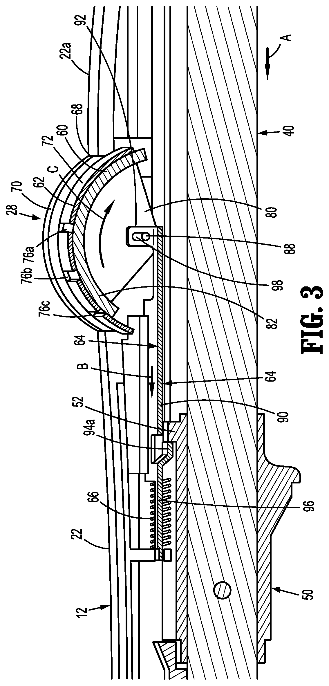
Referring also to FIG. 3, the anvil assembly 18 is supported on the distal end of an approximation mechanism (not shown in its entirety) that includes the rotation knob 26, an anvil retainer (not shown) and the drive screw 40 (FIG. 3). The rotation knob 26 is operably coupled to a proximal end of the drive screw 40 and the anvil retainer (not shown) is coupled to a distal end of the drive screw 40 such that actuation of the rotation knob 26 retracts and advances the drive screw 40 within the stationary handle 22 to move the anvil assembly 18 in relation to the cartridge assembly 16 between the spaced position (FIG. 1) and the approximated position (FIG. 2). A screw stop 50 is fixedly supported on the drive screw 40 and includes an abutment 52 as described in further detail below. Further details of the approximation mechanism are provided in the '106 patent.
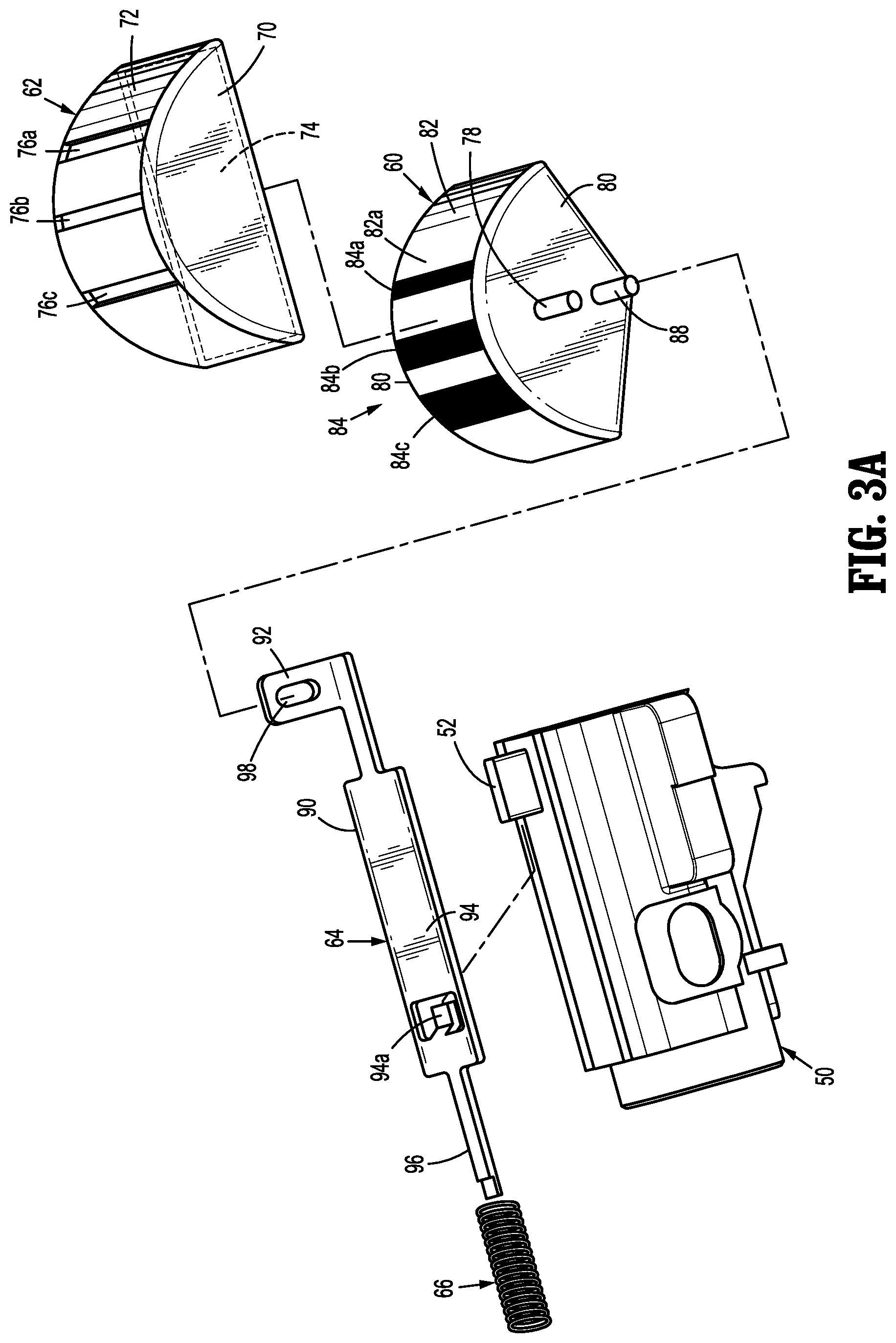
The rotation knob 26 is manually rotated to approximate the anvil assembly 18 and the cartridge assembly 16. More specifically, when the rotation knob 26 is manually rotated in a first direction, the drive screw 40 is moved proximally within the stationary handle 22 from an advanced position towards a retracted position. As discussed above, the lockout mechanism 30 prevents actuation of the firing trigger 24 through an actuation stroke until the anvil assembly 18 is closely approximated with the cartridge assembly 16 to within the firing zone. After the cartridge assembly 16 and the anvil assembly 18 are approximated to within the firing zone, the tissue gap defined between the anvil assembly 18 and the cartridge assembly 16 is further adjustable to accommodate tissues of different thicknesses as described in further detail below.
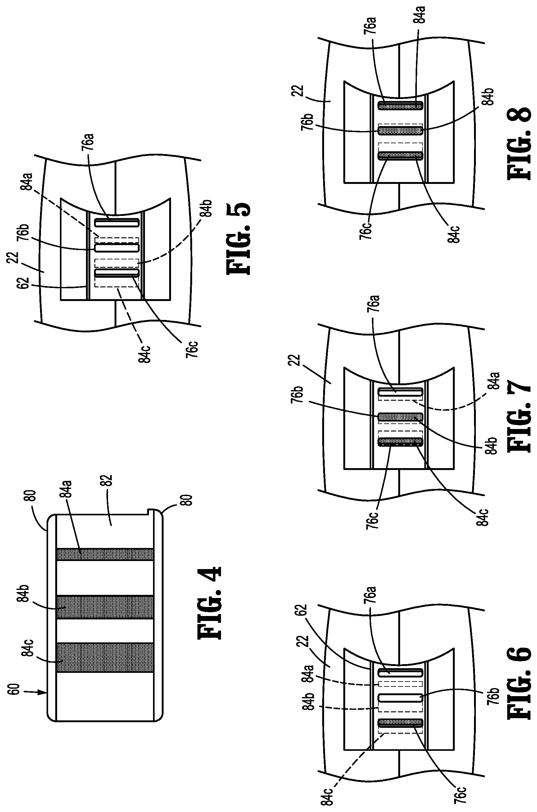
Referring to FIGS. 3-4, the indicator assembly 28 includes an indicator 60, an indicator cover 62, an indicator plate 64 and a biasing member 66. The indicator cover 62 is positioned over an opening or window 68 defined in an upper surface 22a of the stationary handle 22 and includes a pair of sidewalls 70, a curved upper wall 72 supported on the upper edge of the sidewalls 70 and an open bottom 74. The curved upper wall 72 is positioned above the upper surface 22a of the stationary handle 22 and defines three spaced slots 76a-c that allow for visualization of the indicator 60 within the stationary handle 22 as described in further detail below.
The indicator 60 has a shape that corresponds to the shape of the indicator cover 62 and is pivotally supported within the window 68 of the stationary handle 22 (FIG. 1) beneath the indicator cover 62 about a pivot member 78. More specifically, the indicator 60 includes a pair of spaced sidewalls 80 and a curved upper wall 82 supported on the top edge of the sidewalls 80. The curved upper wall 82 includes an upper surface 82a (FIG. 3A) that supports indicia 84. In embodiments, the indicia 84 include three colored stripes or bands 84a-c. Alternately, other types of indicia may be used including symbols, letters, and/or numbers. The indicator 60 is pivotally supported within the indicator cover 62 on a pivot member 78. One of the sidewalls 80 of the indicator 60 supports an engagement member 88 (FIG. 3A) that is described in further detail below.
In embodiments, the indicator plate 64 includes a body 90 having a distal end defining a coupling member 92, a central portion 94 defining a stop surface 94a, and a proximal end including a proximally extending finger 96. The stop surface 94a is positioned to engage the abutment 52 on the screw stop 50 when the drive screw 40 is retracted within the stationary handle 22 to approximate the cartridge and anvil assemblies 16, 18. The indicator plate 64 is slidably supported within the stationary handle 22, e.g., along grooves defined along inner walls of the stationary handle 22. The coupling member 92 defines a vertically extending elongated slot 98 that receives the engagement member 88 of the indicator 60 and the finger 96 of the indicator plate 64 extends through a bracket 100 defining a cutout 100a defined within the stationary housing 22 to guide movement of the indicator plate 64 between advanced and retracted positions. The biasing member 66, which may be a coil spring, is positioned about the finger 96 between the distal end of the bracket 100 and the proximal end of the central portion 94 of the indicator plate 64 to urge the indicator plate 64 towards the advanced position.
In use, when the rotation knob 26 (FIG. 1) is rotated to move the drive screw 40 in the direction indicated by arrow "A" in FIG. 3 towards its retracted position to move the anvil assembly 18 towards the cartridge assembly 16, the abutment 52 on the screw stop 50 moves into engagement with the stop member 94a on the indicator plate 64 to pull the indicator plate 64 proximally with the drive screw 40 in the direction indicated by arrow "B" in FIG. 3 against the force of the biasing member 66. As the indicator plate 64 is moved from its advanced position towards its retracted position in the direction indicated by arrow "B", the coupling member 92 of the indicator plate 64 pulls the engagement member 88 of the indicator 60 to pivot the indicator 60 in the direction indicted by arrow "C" in FIG. 3.
Referring to FIG. 5, prior to approximation of the cartridge and anvil assemblies 16, 18 into the firing zone, each of the colored bands 84a-c of the indicator 60 is positioned adjacent a respective one of the slots 76a-c of the indicator cover 62. As shown in FIG. 5, when the indicator 60 is in its non-actuated position prior to pivotal movement by the indicator plate 64, the distance between the colored band 84c and the slot 76c is less than the distance between the colored band 84b and the slot 76b, and the distance between the colored band 84b and the slot 76b is less than the distance between the colored band 84a and the slot 76a. As such, when the indicator 60 is pivoted in the direction indicated by arrow "C" in FIG. 3 into the firing zone, the colored band 84c will appear in the slot 76c prior to the colored bands 84b and 84a appearing in slots 76b and 76a. When the colored band 84c appears in the slot 76c, this indicates to a clinician that the anvil head 34 of the anvil assembly 18 has been approximated in relation to the staple cartridge 38a (FIG. 2) to a maximum gap position in the firing zone. The maximum gap position in the firing zone is the position in which the anvil head 34 and the staple cartridge 38a define the largest tissue gap in the firing zone and is suitable for treating relatively thick tissue.
When the drive screw 40 is retracted further in the direction indicated by arrow "A" in FIG. 3, the abutment 52 of the screw stop 50 continues to pull the indicator plate 64 proximally against the force of the biasing member 66 to further pivot the indicator 60 in the direction indicated by arrow "C" in FIG. 3. As the indicator 60 continues to pivot, the colored band 84c, which is thicker than bands 84a and 84b, remains visible through slot 76c and the colored band 84b appears in the slot 76b. The colored band 84a, which is thinner than colored band 84b, approaches slot 76a but is not yet visible through slot 76a. When the colored band 84b appears in the slot 76b, this indicates to a clinician that the anvil head 34 of the anvil assembly 18 has been approximated to an intermediate gap position smaller than the maximum gap position in the firing zone. The intermediate gap position in the firing zone is suitable for treating tissue of intermediate thickness.
When the drive screw 40 is retracted further in the direction indicated by arrow "A" in FIG. 3 to its fully retracted position, the abutment 52 of the screw stop 50 continues to pull the indicator plate 64 proximally against the force of the biasing member 66 to further pivot the indicator 60 in the direction indicated by arrow "C" in FIG. 3. As the indicator continues to pivot, the colored band 84c and 84b which are thicker than band 84a remain visible through slots 76c and 76b and the colored band 84a appears in the slot 76a. When the colored band 84a appears in the slot 76a, this indicates to a clinician that the anvil head 34 of the anvil assembly 18 has been approximated to a minimum gap position smaller than the intermediate tissue gap in the firing zone. The minimum gap position in the firing zone is suitable for treating tissue of relatively small thicknesses.
As discussed above, the colored bands 84a-c may have different thicknesses. More specifically, to ensure that the colored band 84c remains visible under slot 76c and that the colored band 84b remains visible under slot 76b as the indicator 60 is pivoted through the firing zone, the colored band 84c may have a thickness greater than colored bands 84b and 84a, and the colored band 84b may have a thickness greater than the thickness of colored band 84a.
FIGS. 9-12 illustrate another embodiment of the presently disclosed visual indicator assembly shown generally as 128. Indicator assembly 128 is substantially the same as indicator assembly 28 except that the configuration of the slots 176a-c and the configuration of the indicia 84 has been changed. More specifically, the indicator cover 162 of the indicator assembly 128 includes slots 176a-c that are longitudinally and laterally offset from each other and the indicator 160 includes a single stepped colored band 184 having three steps 184a-c. Each of the steps 184a-c of the colored band 184 is laterally aligned with a respective one of the slots 176a-c.
As shown in FIGS. 9 and 10, the distance between the step 184c of the colored band 184 and the slot 176c is less than the distance between the step 184b of the colored band 184 and the slot 176b and the distance between the step 184b and the colored band 184 and the slot 176b is less than the distance between the step 184a of the colored band 184 and the slot 176a. As such, when the indicator 60 is pivoted in the direction indicated by arrow "C" in FIG. 3 into the firing zone, the step 184c of the colored band 184 will appear in the slot 176c prior to the steps 184b and 184a of colored bands 184 appearing in slots 176b and 176a, respectively. Similarly, the step 184b of the colored band 184 will appear in the slot 176b prior to the step 184a of colored band 184 appearing in slot 176a.
Operation of the indicator assembly 128 is substantially as described above in regard to indicator assembly 28. As such, no further description of the indicator assembly 128 is provided herein.
Persons skilled in the art will understand that the devices and methods specifically described herein and illustrated in the accompanying drawings are non-limiting exemplary embodiments. It is envisioned that the elements and features illustrated or described in connection with one exemplary embodiment may be combined with the elements and features of another without departing from the scope of the present disclosure. As well, one skilled in the art will appreciate further features and advantages of the disclosure based on the above-described embodiments. Accordingly, the disclosure is not to be limited by what has been particularly shown and described, except as indicated by the appended claims.
* * * * *
D00000
D00001
D00002
D00003
D00004
D00005
XML
uspto.report is an independent third-party trademark research tool that is not affiliated, endorsed, or sponsored by the United States Patent and Trademark Office (USPTO) or any other governmental organization. The information provided by uspto.report is based on publicly available data at the time of writing and is intended for informational purposes only.
While we strive to provide accurate and up-to-date information, we do not guarantee the accuracy, completeness, reliability, or suitability of the information displayed on this site. The use of this site is at your own risk. Any reliance you place on such information is therefore strictly at your own risk.
All official trademark data, including owner information, should be verified by visiting the official USPTO website at www.uspto.gov. This site is not intended to replace professional legal advice and should not be used as a substitute for consulting with a legal professional who is knowledgeable about trademark law.