Operation method for improving partial load efficiency in a gas turbine and gas turbine with improved partial load efficiency
Asti , et al. December 22, 2
U.S. patent number 10,871,109 [Application Number 15/549,802] was granted by the patent office on 2020-12-22 for operation method for improving partial load efficiency in a gas turbine and gas turbine with improved partial load efficiency. This patent grant is currently assigned to NUOVO PIGNONE TECNOLOGIE SRL. The grantee listed for this patent is Nuovo Pignone Tecnologie Srl. Invention is credited to Antonio Asti, Riccardo Carta, Luciano Mei.

| United States Patent | 10,871,109 |
| Asti , et al. | December 22, 2020 |
Operation method for improving partial load efficiency in a gas turbine and gas turbine with improved partial load efficiency
Abstract
A method for improving partial load efficiency in a gas turbine engine including a compressor, burners, a high pressure turbine and a low pressure turbine; including the step of operating the gas turbine engine by regulating at least: air mass flow rate and flame temperature; regulation is carried out by controlling at least: the air mass flow rate supplied to the combustion chamber from the compressor, and the number of operating burners, and the change in enthalpy drop between the high and low pressure turbine to control the air mass flow rate.
| Inventors: | Asti; Antonio (Florence, IT), Mei; Luciano (Florence, IT), Carta; Riccardo (Florence, IT) | ||||||||||
|---|---|---|---|---|---|---|---|---|---|---|---|
| Applicant: |
|
||||||||||
| Assignee: | NUOVO PIGNONE TECNOLOGIE SRL
(Florence, IT) |
||||||||||
| Family ID: | 1000005256745 | ||||||||||
| Appl. No.: | 15/549,802 | ||||||||||
| Filed: | February 10, 2016 | ||||||||||
| PCT Filed: | February 10, 2016 | ||||||||||
| PCT No.: | PCT/EP2016/052848 | ||||||||||
| 371(c)(1),(2),(4) Date: | August 09, 2017 | ||||||||||
| PCT Pub. No.: | WO2016/128479 | ||||||||||
| PCT Pub. Date: | August 18, 2016 |
Prior Publication Data
| Document Identifier | Publication Date | |
|---|---|---|
| US 20180030903 A1 | Feb 1, 2018 | |
Foreign Application Priority Data
| Feb 12, 2015 [IT] | CO2015A0002 | |||
| Current U.S. Class: | 1/1 |
| Current CPC Class: | F02C 9/22 (20130101); F02C 9/18 (20130101); F02C 9/52 (20130101); F02C 9/54 (20130101); F05D 2270/3061 (20130101) |
| Current International Class: | F02C 9/00 (20060101); F02C 9/18 (20060101); F02C 9/54 (20060101); F02C 9/22 (20060101); F02C 9/52 (20060101) |
References Cited [Referenced By]
U.S. Patent Documents
| 4539810 | September 1985 | Watanabe |
| 4683715 | August 1987 | Iizuka |
| 4766721 | August 1988 | Iizuka et al. |
| 5996347 | December 1999 | Nagae |
| 2006/0021354 | February 2006 | Mowill |
| 2007/0074516 | April 2007 | Peck |
| 2007/0227156 | October 2007 | Saito |
| 2009/0158702 | June 2009 | Tonno et al. |
| 2011/0270447 | November 2011 | Allegorico et al. |
| 2015/0040573 | February 2015 | Ferreira-Providakis et al. |
| 2016/0348690 | December 2016 | Larson et al. |
| 2 383 452 | Nov 2011 | EP | |||
| 2835516 | Feb 2015 | EP | |||
| S5910742 | Jan 1984 | JP | |||
| S62175524 | Aug 1987 | JP | |||
| 2004093076 | Mar 2004 | JP | |||
| 2009150391 | Jul 2009 | JP | |||
| 2011236895 | Nov 2011 | JP | |||
Other References
|
NASA, Turbine Thermodynamics, Feb. 3, 2012 (Year: 2012). cited by examiner . Search Report and Written Opinion issued in connection with corresponding IT Application No. CO2015A000002 dated Oct. 16, 2015. cited by applicant . International Search Report and Written Opinion issued in connection with corresponding WO Application No. PCT/EP2016/052848 dated Apr. 29, 2016. cited by applicant. |
Primary Examiner: Manahan; Todd E
Assistant Examiner: Kang; Edwin
Attorney, Agent or Firm: Baker Hughes Patent Org.
Claims
What is claimed is:
1. A method for improving partial load efficiency in a gas turbine engine comprising a compressor, operating burners, a high pressure turbine and a low pressure turbine, the method comprising: operating the gas turbine engine by regulating at least: an air mass flow rate, and a flame temperature, controlling at least: the air mass flow rate supplied to a combustion chamber from the compressor; a number of the operating burners; and a change in an enthalpy drop between the high and low pressure turbine to control the air mass flow rate; wherein the air mass flow rate supplied to the combustion chamber from the compressor comprises a bleed that extracts a fraction of the air mass flow rate of the compressor at a compressor stage more upstream of a discharge, to limit a loss of work, in which a bleed flow rate supplied to the combustion chamber is modified, and the number of the operating burners comprises an annular combustor staging, in which the number of operating burners is modified, and the change in the enthalpy drop between the high and low pressure turbine to control the air mass flow rate comprises a nozzle guide vane control, in which the change in the enthalpy drop between the high and low pressure turbine is modified, allowing for regulation of the air mass flow rate, and at a lower load range, less than a first separating load value, operating the gas turbine engine by only controlling the bleed flow rate so as to limit the loss of work, at an intermediate load range, more than the first separating load value and less than a second separating load value, operating the gas turbine engine by only controlling the annular combustor staging so as to limit a thermal distortion of hot gas path components, at an upper load range, more than the second separating load value and less than a full operating load value, operating the gas turbine engine by only controlling a plurality of nozzle guide vanes, so as to regulate the air mass flow rate.
2. The method of claim 1, wherein the first separating load value is tunable, in a range comprised between 15% and 25% of a maximum turbine engine load, and/or the second separating load value is tunable, preferably in a range comprised between 35% and 45% of the maximum turbine engine load, and/or the upper load range is tunable, substantially equal to 98%, of the maximum turbine engine load.
3. The method of claim 1, wherein a control of the bleed flow rate of the compressor decreases between 0% (idle) and the first separating load value.
4. The method of claim 1, wherein the annular combustor staging provides at least for augmenting the number of the operating burners from a minimum number of the operating burners at the first separating load value to a maximum number of the operating burners at the second separating load value, the maximum number of the operating burners being equal to the maximum number of the operating burners in the turbine engine.
5. The method of claim 1, wherein controlling the plurality of nozzle guide vanes provides at least for augmenting the enthalpy drop in the high pressure turbine from a minimum value at the second separating load value to a maximum value at the upper load range, the enthalpy drop being regulated by regulating a throat area of nozzles located upstream the low pressure turbine, by rotating airfoils.
6. The method of claim 1, wherein the bleed flow rate comes from an intermediate stage of the compressor, different from the discharge of the compressor.
Description
TECHNICAL FIELD
Embodiments of the subject matter disclosed herein correspond to methods for improving partial load efficiency in a gas turbine engine (often referred to simply as "gas turbine") and gas turbine engines having an improved partial load efficiency.
BACKGROUND OF THE INVENTION
In the last years it has became more and more relevant controlling gas turbine operation obtaining high efficiency and/or low emissions at part load.
In such operative condition known gas turbine shows relatively low efficiency and/or high emissions, particularly NOx emissions.
When low-emissions premixed combustors are used, the reaction temperature must be kept as close as possible to the design value: in order to do this, it is necessary to develop some kind of control of the airflow that enters the combustion chamber.
Solutions for controlling part load operation of a gas turbine are known.
One known solution is to control, during the gas turbine operation, two degrees of freedom (in the part load operating range of the turbine); particularly it is known to provide a control for the compressor bleed and for the combustor staging.
Briefly, the "bleed" is a valve, usually located at the compressor discharge, that expels a fraction of the compressed air upstream the combustion chamber. This system dissipates part of the work spent in the compression.
On its turn, controlling the combustor staging implies to selectively turn off some of the burners, in order to let the active ones run at a stable fuel/air ratio. When performed at high power level, this approach causes thermal distortions on hot gas path components.
BRIEF DESCRIPTION OF THE INVENTION
Therefore there is a general need for a method for improving partial load efficiency in a gas turbine and a turbine having an improved partial load efficiency.
An important idea is to provide the gas turbine engine operation at part load controlling the gas turbine engine with three degrees of freedom, namely controlling a bleed flow rate of fluid of the compressor (more upstream than the compressor discharge), to limit the loss of work, a combustor staging and a nozzle guide vanes (NGV) control.
In this way it is possible to achieve a great versatility in controlling the main gas turbine engine parameters so as to achieve high efficiency and/or low emissions at part load.
One embodiment of the subject matter disclosed herein correspond to a method for improving partial load efficiency in a gas turbine engine comprising a compressor, burners, an high pressure turbine and a low pressure turbine, wherein the method comprises the step of operating the gas turbine engine by regulating at least an air mass flow rate and the flame temperature.
Such parameters (air mass flow rate and the flame temperature) are regulated by controlling at least: an air mass flow rate supplied to the combustion chamber from the compressor, and the number of operating burners, and the change in enthalpy drop between the high and low pressure turbine to control the air mass flow rate.
Still more particularly, the step a comprises a bleed that extracts a fraction of the flow rate of fluid of the compressor at a compressor stage more upstream of the discharge, to limit the loss of work, in which the bleed flow rate supplied to the combustion chamber is modified, and/or the step b comprises an annular combustor staging, in which the number of operating burners is modified, and/or the step c comprises a nozzle guide vane (NGV) control, in which the change in enthalpy drop between the high and low pressure turbine is modified, allowing for air mass flow rate regulation.
In other words, the method for improving partial load efficiency in a gas turbine engine provides for controlling, at part load, two degrees of freedom: a bleed flow rate of fluid of the compressor (ASV), in which the bleed flow rate supplied to the combustion chamber is modified, and an annular combustor staging, in which the number of operating burners is modified; wherein the method further comprises the step of controlling at least a third degree of freedom, said third degree of freedom being: a nozzle guide vanes (NGV) control, in which the change in enthalpy drop between the high and low pressure turbine is modified, allowing for air mass flow rate control.
Embodiments of the subject matter disclosed herein correspond to a gas turbine engine comprising a compressor, burners, an high pressure turbine and a low pressure turbine, said gas turbine engine further comprising a bleed flow piping of the compressor operatively connected to the high pressure turbine, an annular combustor staging device comprising said burners and a nozzle guide vane (NGV) control device.
BRIEF DESCRIPTION OF DRAWINGS
The accompanying drawings, which are incorporated herein and constitute a part of the specification, illustrate exemplary embodiments of the present invention and, together with the detailed description, explain these embodiments. In the drawings:
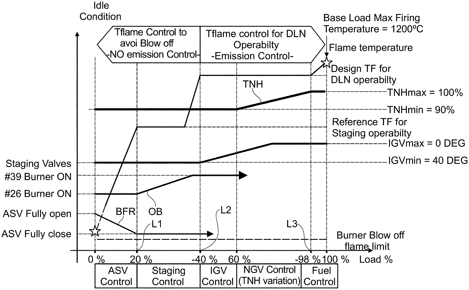
FIG. 1 shows a control diagram of an exemplary method herein disclosed, and
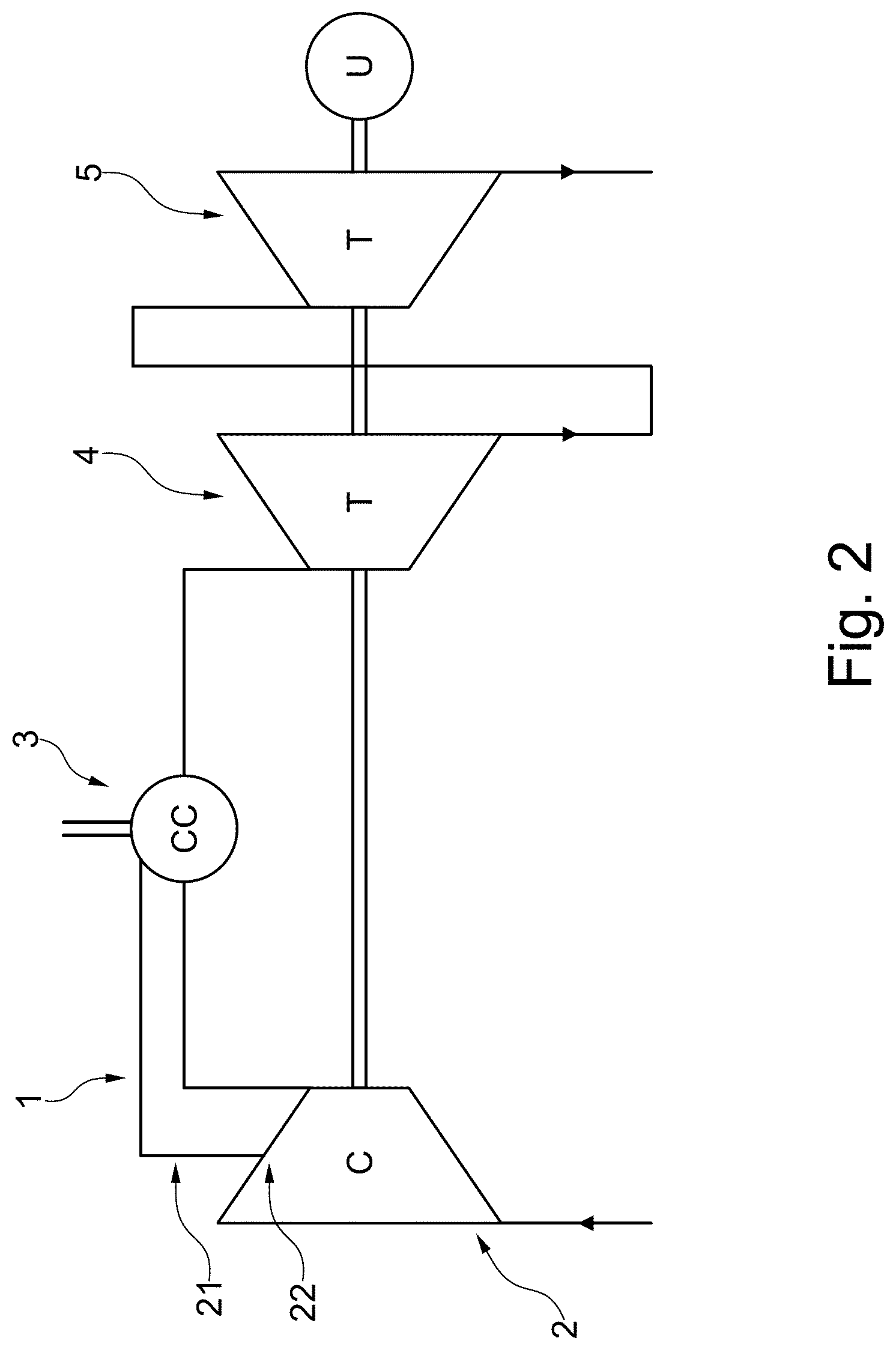
FIG. 2 shows a simplified gas turbine engine scheme.
DETAILED DESCRIPTION
The following description of exemplary embodiments refers to the accompanying drawings.
The following description does not limit the invention. Instead, the scope of the invention is defined by the appended claims.
Reference throughout the specification to "one embodiment" or "an embodiment" means that a particular feature, structure, or characteristic described in connection with an embodiment is included in at least one embodiment of the subject matter disclosed. Thus, the appearance of the phrases "in one embodiment" or "in an embodiment" in various places throughout the specification is not necessarily referring to the same embodiment. Further, the particular features, structures or characteristics may be combined in any suitable manner in one or more embodiments.
One embodiment of a method for improving partial load efficiency herein described applies to a gas turbine engine as shown in FIG. 2.
As can be seen, the gas turbine engine 1, embodiment of the subject matter herein described, comprises a compressor 2, burners 3, an high pressure turbine 4 and a low pressure turbine 5, downstream of the first one.
According to the teaching herein given, the turbine engine 1 comprises also a bleed flow piping 21 of the compressor operatively connected to the high pressure turbine 4.
In an embodiment, the bleed flow piping 21 is operatively connected to an intermediate stage 22 of the compressor, different from the main outlet of the compressor 2, the bleed flow piping 21 is therefore operatively connected to a compressor stage more upstream of the discharge (main outlet) of the compressor itself.
In an embodiment, if said intermediate stage 22 of the compressor 2 comprises an anti surge valve ASV system, then the bleed flow piping 21 can be either a different piping from the anti surge valve ASV system, or can be the same piping of the anti surge valve ASV system.
In the latter case, said anti-surge valve system comprises also a regulation valve (not shown) that provides both for mass flow regulation (for the bleed flow piping 21) and for anti-surge purposes.
Furthermore, the gas turbine engine 1 also comprises an annular combustor staging device comprising said burners 3, of the type well known per se; briefly said device comprises an activation device for at least some of the, burners, said activation device being at least one valve per each burner.
Furthermore, the gas turbine engine 1 comprises also a nozzle guide vane (NGV) control device, known per se in the art; this device, briefly, comprises an actuator acting on a ring that on its turn moves pins coupled to the nozzle airfoils that open or closes the throat area of each nozzle thereby regulating enthalpy drop.
With reference to FIG. 1, another embodiment of the subject matter is a method for improving partial load efficiency in a gas turbine engine 1 comprising a compressor 2, burners 3, an high pressure turbine 4 and a low pressure turbine 5, wherein the method comprises the step of operating the gas turbine engine by regulating at least: an air mass flow rate, flame temperature, by means of controlling at least: an air mass flow rate supplied to the combustion chamber from the compressor, the number of operating burners, the change in enthalpy drop between the high and low pressure turbine to control the air mass flow rate.
In an embodiment, the step a comprises a bleed that extracts a fraction of the flow rate of fluid of the compressor at a compressor stage more upstream of the discharge, to limit the loss of work, in which the bleed flow rate supplied to the combustion chamber is modified.
In an embodiment, the step b comprises an annular combustor staging, in which the number of operating burners is modified.
In an embodiment, the step c comprises a nozzle guide vane (NGV) control, in which the change in enthalpy drop between the high and low pressure turbine is modified, allowing for air mass flow rate regulation: the regulation of the enthalpy drop on high pressure turbine allows to modify the shaft speed and therefore the air mass flow rate.
Those controls are performed at different load of the turbine, as is depicted in FIG. 2.
According to an optional feature, at a lower load range, less than a first separating load value L1, the gas turbine engine is operated by controlling the bleed flow rate (ASV) so as to limits the loss of work, while at an intermediate load range, more than the first separating load value and less than a second separating load value L2, the gas turbine engine is operated by controlling the annular combustor staging so as to limit the thermal distortion of the hot gas path components, while at an upper load range, more than the second separating load value and less than a full (upper) operating load value L3, the gas turbine engine is operated by controlling the nozzle guide vane (NGV), so as to regulate the air mass flow rate.
For what concern the first L1, second L2 and upper L3 separating load values, in principle they are tunable and can be changed for operational purposes.
In an embodiment, with reference to FIG. 1, the first separating load value L1 is in a range comprised between 15% and 25%, still more particularly substantially equal to 20%, of a maximum turbine engine load and the second separating load value L2 is in an embodiment in a range comprised between 35% and 45%, still more particularly substantially equal to 40%, of a maximum turbine engine load.
The upper load range value L3 is in an embodiment substantially equal to 98%, of a maximum turbine engine load.
For what concern the control of the bleed flow rate of the compressor, it is provided at least bleeding--from the compressor--a flow rate of fluid, referenced as BFR in FIG. 1, decreasing, in an embodiment linearly decreasing, between an engine load between 0% (idle) and the first separating load value L1.
The bleed flow comes from an intermediate stage of the compressor, different from the main outlet of the compressor, in an embodiment from an intermediate stage of the compressor comprising an anti surge valve system ASV, as above described; to this extent in FIG. 1 that control is indicated ad "ASV control".
For what concerns the control of the annular combustor staging, it is provided at least for augmenting, and in an embodiment linearly augmenting, a number of operating burners, referenced as OB in FIG. 1, from a minimum number of operating burners at the first separating load value to a maximum number of operating burners at the second separating load value; to this extent in FIG. 1 that control is indicated ad "staging control".
In an embodiment, said maximum number of operating burners is equal to the maximum number of the burners in the turbine engine.
On its turn, the control of nozzle guide vane (NGV) provides at least for augmenting, in an embodiment, linearly augmenting the enthalpy drop in the high pressure turbine from a minimum value at the second separating load value to a maximum value at the upper load range; this regulation is in an embodiment linear as indicated in FIG. 1 and referenced with "TNH".
Such enthalpy drop is regulated for example by means of regulating a throat area of nozzles located upstream the power turbine, by means of rotating airfoils.
This written description uses examples to disclose the invention, including the preferred embodiments, and also to enable any person skilled in the art to practice the invention, including making and using any devices or systems and performing any incorporated methods. The patentable scope of the invention is defined by the claims, and may include other examples that occur to those skilled in the art. Such other examples are intended to be within the scope of the claims if they have structural elements that do not differ from the literal language of the claims, or if they include equivalent structural elements with insubstantial differences from the literal languages of the claims.
* * * * *
D00000
D00001
D00002
XML
uspto.report is an independent third-party trademark research tool that is not affiliated, endorsed, or sponsored by the United States Patent and Trademark Office (USPTO) or any other governmental organization. The information provided by uspto.report is based on publicly available data at the time of writing and is intended for informational purposes only.
While we strive to provide accurate and up-to-date information, we do not guarantee the accuracy, completeness, reliability, or suitability of the information displayed on this site. The use of this site is at your own risk. Any reliance you place on such information is therefore strictly at your own risk.
All official trademark data, including owner information, should be verified by visiting the official USPTO website at www.uspto.gov. This site is not intended to replace professional legal advice and should not be used as a substitute for consulting with a legal professional who is knowledgeable about trademark law.