Vehicle wheel support device
Hashimoto , et al. December 22, 2
U.S. patent number 10,870,439 [Application Number 16/087,592] was granted by the patent office on 2020-12-22 for vehicle wheel support device. This patent grant is currently assigned to MITSUBISHI ELECTRIC CORPORATION. The grantee listed for this patent is MITSUBISHI ELECTRIC CORPORATION. Invention is credited to Michinori Hashimoto, Hideo Terasawa.


| United States Patent | 10,870,439 |
| Hashimoto , et al. | December 22, 2020 |
Vehicle wheel support device
Abstract
Two support frames support opposite wheels rollably on a rail and support the vehicle body through suspension systems. At one end, four L-shaped links and four support links are each coupled, bilaterally symmetrically and in front of and behind the wheels, to the two support frames in a manner allowing rotation on the support frames about an axis in the front-rear direction below and above the center axis of the wheels. In a bending portion in the middle, the L-shaped links are supported by the vehicle body rotatably about an axis in the front-rear direction, and the L-shaped links and support links are coupled at the other end to each other so as to allow rotation about an axis in the front-rear direction.
| Inventors: | Hashimoto; Michinori (Tokyo, JP), Terasawa; Hideo (Tokyo, JP) | ||||||||||
|---|---|---|---|---|---|---|---|---|---|---|---|
| Applicant: |
|
||||||||||
| Assignee: | MITSUBISHI ELECTRIC CORPORATION
(Tokyo, JP) |
||||||||||
| Family ID: | 1000005256116 | ||||||||||
| Appl. No.: | 16/087,592 | ||||||||||
| Filed: | March 29, 2016 | ||||||||||
| PCT Filed: | March 29, 2016 | ||||||||||
| PCT No.: | PCT/JP2016/060048 | ||||||||||
| 371(c)(1),(2),(4) Date: | September 21, 2018 | ||||||||||
| PCT Pub. No.: | WO2017/168546 | ||||||||||
| PCT Pub. Date: | October 05, 2017 |
Prior Publication Data
| Document Identifier | Publication Date | |
|---|---|---|
| US 20190084592 A1 | Mar 21, 2019 | |
| Current U.S. Class: | 1/1 |
| Current CPC Class: | B61F 3/16 (20130101); B61F 5/06 (20130101); B61F 5/52 (20130101) |
| Current International Class: | B61F 3/16 (20060101); B61F 5/06 (20060101); B61F 5/52 (20060101) |
References Cited [Referenced By]
U.S. Patent Documents
| 2477517 | July 1949 | Haynes |
| 3570408 | March 1971 | Lich |
| 3661097 | May 1972 | Jackson |
| 3774550 | November 1973 | Lich |
| 3817188 | June 1974 | Lich |
| 5546868 | August 1996 | Sugimoto |
| 2000309268 | Nov 2000 | JP | |||
| 2015100249 | May 2015 | JP | |||
Other References
|
International Search Report (PCT/ISA/210) dated May 17, 2016, by the Japan Patent Office as the International Searching Authority for International Application No. PCT/JP2016/060048. cited by applicant . Written Opinion (PCT/ISA/237) dated May 17, 2016, by the Japan Patent Office as the International Searching Authority for International Application No. PCT/JP2016/060048. cited by applicant. |
Primary Examiner: Le; Mark T
Attorney, Agent or Firm: Buchanan Ingersoll & Rooney PC
Claims
The invention claimed is:
1. A vehicle wheel support device for supporting wheels of a vehicle that runs on a railroad track including two rails laid parallel to each other, comprising: a first support frame rotatably supporting a first wheel so that the first wheel can roll on one of the rails, the first support frame supporting a vehicle body of the vehicle through a suspension system; a second support frame rotatably supporting a second wheel facing the first wheel in a lateral direction orthogonal to a traveling direction of the vehicle so that the second wheel can roll on the other of the rails, the second support frame supporting the vehicle body through a suspension system; first to fourth L-shaped links each having a middle bending portion that is pivotally supported by the vehicle body; and first to fourth support links, one ends of which are respectively pivotally joined to upper ends of the first to fourth L-shaped links, wherein the first and third L-shaped links are disposed symmetrically in the lateral direction with respect to the second and fourth L-shaped links, the first and third L-shaped links are pivotally supported by a lower portion of the first support frame, and other ends of the first and third support links one ends of which are respectively joined to the upper ends of the first and third L-shaped links, are pivotally joined to an upper portion of the second support frame, the second and fourth L-shaped links are pivotally supported by a lower portion of the second support frame, and other ends of the second and fourth support links one ends of which are respectively joined to the upper ends of the second and fourth L-shaped links, are pivotally joined to an upper portion of the first support frame.
2. The vehicle wheel support device according to claim 1, wherein the first to fourth L-shaped links and the first to fourth support links support the first support frame and the second support frame, to enable maintenance of: (i) a transverse wheel distance between the first and second wheels, and (ii) an angle between the first wheel and a railroad track plane and an angle between the second wheel and the railroad track plane against up-and-down movements of the vehicle body and an inclination of the vehicle body in the lateral direction, the railroad track plane being a plane touching upper surfaces of the two rails.
3. The vehicle wheel support device according to claim 1, wherein the first L-shaped link, the second L-shaped link, the first support link and the second support link are arranged more forward than central axes of the first wheel and the second wheel in a front-rear direction parallel to the traveling direction of the vehicle, and the third L-shaped link, the fourth L-shaped link, the third support link and the fourth support link are arranged more backward than the central axes of the first wheel and the second wheel in the front-rear direction.
4. The vehicle wheel support device according to claim 1, wherein the first L-shaped link and the third L-shaped link are pivotally supported by the first support frame below the central axis of the first wheel, the second L-shaped link and the fourth L-shaped link are pivotally supported by the second support frame below the central axis of the second wheel, one ends of the first support link and the third support link are respectively pivotally joined to the upper ends of the first L-shaped link and the third L-shaped link, and other ends of the first support link and the third support link are pivotally supported by the second support frame above the central axis of the second wheel, and one ends of the second support link and the fourth support link are respectively pivotally joined to the upper ends of the second L-shaped link and the fourth L-shaped link, and other ends of the second support link and the fourth support link are pivotally supported by the first support frame above the central axis of the first wheel.
5. The vehicle wheel support device according to claim 1, wherein as viewed in projection on a plane orthogonal to a front-rear direction parallel to the traveling direction of the vehicle in a state in which the first wheel and the second wheel are motionless on the horizontal railroad track plane: (a) a position of a shaft of the first L-shaped link joining the first L-shaped link to the first support frame matches a position of a shaft of the third L-shaped link joining the third L-shaped link to the first support frame, (b) position of a shaft of the second L-shaped link joining the second L-shaped link to the second support frame matches a position of a shaft of the fourth L-shaped link joining the fourth L-shaped link to the second support frame, (c) a position of a shaft of the first L-shaped link joining the first L-shaped link to the vehicle body matches a position of a shaft of the third L-shaped link joining the third L-shaped link to the vehicle body, (d) a position of a shaft of the second L-shaped link joining the second L-shaped link to the vehicle body matches a position of a shaft of the fourth L-shaped link joining the fourth L-shaped link to the vehicle body, (e) a position of a shaft of the first L-shaped link joining the first L-shaped link to the first support link matches a position of a shaft of the third L-shaped link joining the third L-shaped link to the third support link, (f) a position of a shaft of the second L-shaped link joining the second L-shaped link to the second support link matches a position of a shaft of the fourth L-shaped link joining the fourth L-shaped link to the fourth support link, (g) a position of a shaft of the first support link joining the first support link to the second support frame matches a position of a shaft of the third support link joining the third support link to the second support frame, and (h) a position of a shaft of the second support link joining the second support link to the first support frame matches a position of a shaft of the fourth support link joining the fourth support link to the first support frame.
6. The vehicle wheel support device according to claim 1, wherein as viewed in projection on the plane orthogonal to a front-rear direction parallel to the traveling direction of the vehicle in the state in which the first wheel and the second wheel are motionless on the horizontal railroad track plane: (a) the position of the shaft of the first L-shaped link joining the first L-shaped link to the first support frame and the position of the shaft of the second L-shaped link joining the second L-shaped link to the second support frame are symmetric with respect to a plane that runs along the center line between the two rails and that is perpendicular to the railroad track plane, (b) the position of the shaft of the first L-shaped link joining the first L-shaped link to the vehicle body and the position of the shaft of the second L-shaped link joining the second L-shaped link to the vehicle body are symmetric with respect to the plane that runs along the center line between the two rails and that is perpendicular to the railroad track plane, (c) the position of the shaft of the first L-shaped link joining the first L-shaped link to the first support link and the position of the shaft of the second L-shaped link joining the second L-shaped link to the second support link are symmetric with respect to the plane that runs along the center line between the two rails and that is perpendicular to the railroad track plane, and (d) the position of the shaft of the first support link joining the first support link to the second support frame and the position of the shaft of the second support link joining the second support link to the first support frame are symmetric with respect to the plane that runs along the center line between the two rails and that is perpendicular to the railroad track plane.
7. The vehicle wheel support device according to claim 1, wherein a distance between the shaft of the first L-shaped link for supporting the first L-shaped link by the vehicle body and the shaft of the second L-shaped link for supporting the second L-shaped link by the vehicle body is defined under a given condition of a gauge distance of a track gauge of the railroad track, and a distance from the shaft of the first L-shaped link joining the first L-shaped link to the first support frame to the shaft of the first L-shaped link for supporting the first L-shaped link by the vehicle body, a distance from the shaft of the first L-shaped link for supporting the first L-shaped link by the vehicle body to the shaft of the first L-shaped link joining the first L-shaped link to the first support link, a distance from the shaft of the first L-shaped link joining the first L-shaped link to the first support link to the shaft of the first support link joining the first support link to the second support frame, a distance from the shaft of the first L-shaped link joining the first L-shaped link to the first support frame to the shaft of the second support link joining the second support link to the first support frame, and an angle between: a shortest line segment from the shaft of the first L-shaped link joining the first L-shaped link to the first support frame to the shaft of the first L-shaped link for supporting the first L-shaped link by the vehicle body; and a shortest line segment from the shaft of the first L-shaped link for supporting the first L-shaped link by the vehicle to the shaft of the first L-shaped link joining the first L-shaped link to the first support link are selected so that a combination of (a) a change in distance between the first and second wheels, (b) a change in angle between the first wheel and the railroad track plane and (c) a change in angle between the second wheel and railroad track plane due to relative movements of the first and second wheels relative to the vehicle body each of which is minimum.
8. The vehicle wheel support device according to claim 1, wherein each of the first support frame and the second support frame comprises a bearing, an inner bearing tube being fitted to an inner periphery of the bearing and fixed to each of the first support frame and the second support frame, and an outer bearing tube being fitted to an outer periphery of the bearing and fitted to each of the first wheel and the second wheel.
9. The vehicle wheel support device according to claim 1, wherein a structure comprising the first to fourth L-shaped links and the first to fourth support links has rotational symmetry with respect to an axis that passes through a central point between the first wheel and the second wheel and that is perpendicular to the railroad track plane in the state in which the first wheel and the second wheel are motionless on the railroad track plane that is in a horizontal state.
10. The vehicle wheel support device according to claim 1, wherein the first to fourth L-shaped links are pivotally joined to the first and second support frames via pin joints, the first to fourth L-shaped links are pivotally joined to the first to fourth support links via pin joints, and the first to fourth support links are pivotally joined to the first and second support frames via pin joints.
11. The vehicle wheel support device according to claim 1, wherein the first to fourth L-shaped links are joined to the first and second support frames via elastic members, the first to fourth L-shaped links are joined to the first to fourth support links via elastic members, and the first to fourth support links are joined to the first and second support frames via elastic members.
12. The vehicle wheel support device according to claim 1, wherein the first to fourth L-shaped links are joined to the first and second support frames via bearings and elastic members, the first to fourth L-shaped links are joined to the first to fourth support links via bearings and elastic members, and the first to fourth support links are joined to the first and second support frames via bearings and elastic members.
13. The vehicle wheel support device according to claim 1, further comprising: first lower and upper traction links pivotally joined to the first support frame, extending in a front-rear direction parallel to the traveling direction of the vehicle and pivotally supported by the vehicle body; and second lower and upper traction links pivotally joined to the second support frame, extending in the front-rear direction and pivotally supported by the vehicle body.
14. The vehicle wheel support device according to claim 13, wherein the first lower traction link is pivotally joined to the first support frame below the central axis of the first wheel, the second lower traction link is pivotally joined to the second support frame below the central axis of the second wheel, the first upper traction link is pivotally joined to the first support frame above the central axis of the first wheel, and the second upper traction link is pivotally joined to the second support frame above the central axis of the second wheel.
15. The vehicle wheel support device according to claim 13, wherein the first upper traction link, the second upper traction link, the first lower traction link and the second lower traction link are pivotally supported by the vehicle body on the same side of the vehicle wheel support device in the front-rear direction.
16. The vehicle wheel support device according to claim 13, wherein the first upper traction link and the second upper traction link are pivotally joined to the vehicle body on one side of the vehicle wheel support device with respect to the front-rear direction, and the first lower traction link and the second lower traction link are pivotally joined to the vehicle body on the other side of the vehicle wheel support device with respect to the front-rear direction.
17. The vehicle wheel support device according to claim 13, wherein a distance from a shaft of the first upper traction link joining the first upper traction link to the first support frame to a shaft of the first upper traction link supporting the first upper traction link by the vehicle body, a distance from a shaft of the second upper traction link joining the second upper traction link to the second support frame to a shaft of the second upper traction link supporting the second upper traction link by the vehicle body, a distance from a shaft of the first lower traction link joining the first lower traction link to the first support frame to a shaft of the first lower traction link supporting the first lower traction link by the vehicle body, and a distance from a shaft of the second lower traction link joining the second lower traction link to the second support frame to a shaft of the second lower traction link supporting the second lower traction link by the vehicle body are equal to one another.
18. The vehicle wheel support device according to claim 13, wherein a distance from a shaft of the first upper traction link joining the first upper traction link to the first support frame to a shaft of the first upper traction link supporting the first upper traction link by the vehicle body is different from a distance from a shaft of the first lower traction link joining the first lower traction link to the first support frame to a shaft of the first lower traction link supporting the first lower traction link by the vehicle body, and a distance from a shaft of the second upper traction link joining the second upper traction link to the second support frame to a shaft of the second upper traction link supporting the second upper traction link by the vehicle body is different from a distance from a shaft of the second lower traction link joining the second lower traction link to the second support frame to a shaft of the second lower traction link supporting the second lower traction link by the vehicle body.
19. The vehicle wheel support device according to claim 13, wherein the shortest line segment from the shaft of the first upper traction link joining the first upper traction link to the first support frame to the shaft of the first upper traction link supporting the first upper traction link by the vehicle body is parallel to the shortest line segment from the shaft of the first lower traction link joining the first lower traction link to the first support frame to the shaft of the first lower traction link supporting the first lower traction link by the vehicle body, and the shortest line segment from the shaft of the second upper traction link joining the second upper traction link to the second support frame to the shaft of the second upper traction link supporting the second upper traction link by the vehicle body is parallel to the shortest line segment from the shaft of the second lower traction link joining the second lower traction link to the second support frame to the shaft of the second lower traction link supporting the second lower traction link by the vehicle body.
20. The vehicle wheel support device according to claim 13, wherein (a) the shortest line segment from the shaft of the first upper traction link joining the first upper traction link to the first support frame to the shaft of the first upper traction link joining the first upper traction link to the vehicle body and (b) the shortest line segment from the shaft of the first lower traction link joining the first lower traction link to the first support frame to the shaft of the first lower traction link joining the first lower traction link to the vehicle body are disposed such that a linear extension of the (a) shortest line segment intersects a linear extension of the (b) shortest line segment or the (a) shortest line segment is skew to the (b) shortest line segment, and (c) the shortest line segment from the shaft of the second upper traction link joining the second upper traction link to the second support frame to the shaft of the second upper traction link joining the second upper traction link to the vehicle body and (d) the shortest line segment from the shaft of the second lower traction link joining the second lower traction link to the second support frame to the shaft of the second lower traction link joining the second lower traction link to the vehicle body are disposed such that a linear extension of the (c) shortest line segment intersects a linear extension of the (d) shortest line segment or the (c) shortest line segment is skew to the (d) shortest line segment.
Description
TECHNICAL FIELD
The present disclosure relates to a vehicle wheel support device supporting a wheel for a railway vehicle and a vehicle including the vehicle wheel support device.
BACKGROUND ART
Many railway vehicles include a bogie having a structure in which: two wheels are fitted to both ends of each of two wheel shafts with the two wheels separated from each other depending on a track gauge between two rails; and the two wheel shafts with the wheels are arranged on the front side and on the rear side with respect to a direction of travel of a railway vehicle and are supported by a bogie frame. The four wheels are attached to this bogie. A railway vehicle has a configuration in which two bogies, each including two wheel shafts with wheels, are arranged on the front and rear sides of the railway vehicle, and a vehicle body is mounted on the two bogies with the vehicle body straddling the two bogies. In this case, the wheels are supported by fitting the wheels to the wheel shafts.
Recently, a lightweight low-floor vehicle is used for inner-city traffic. Due to lowering of the vehicle floor, a wheel shaft to which the right and left wheels are fixed is not used, but rather a method is used that supports the right and left wheels independently. In this structure, the right-side wheel and the left-side wheel are configured to be rotated separately from each other as the right-side wheel and the left-side wheel are not interconnected. A motor for driving the right-side wheel is different from a motor for driving the left-side wheel, and the right-side wheel and the left-side wheel are controlled separately from each other.
A conventional bogie for independent wheel drive has a structure in which wheels each of which can be individually and separately rotated are arranged on the right side and the left side of a bogie frame. Motors arranged on the right side and the left side of the bogie frame separately drive the wheels arranged on the right side and on the left side. A vehicle with such a conventional bogie can run on rails by rotational driving of the wheels.
For example, a component for independent wheel drive disclosed in Patent Literature 1 has a structure in which each of wheels can be separately rotated. In the component of Patent Literature 1, rotary speeds of motors are decreased by planetary reduction gears and torques of the motors are respectively transmitted through transmission elements to the wheels. A plurality of insertion holes is formed in each of the wheels, pin portions of the transmission elements are inserted into the insertion holes of the wheels, and ring-shaped anti-vibration elements are placed between the insertion holes and the pin portions. Torques from the motors are reliably transmitted to the wheels due to compression of the anti-vibration elements. Also, the anti-vibration elements reduce radial vibration occurring in the wheels.
CITATION LIST
Patent Literature
Patent Literature 1: Unexamined Japanese Patent Application Kokai Publication No. 2000-309268
SUMMARY OF INVENTION
Technical Problem
The bogie for independent wheel drive disclosed in Patent Literature 1 has a structure in which support of wheels is performed using shafts, each protruding outward from a bogie frame in a width direction of a vehicle body, and four wheels for the bogie are supported by the integrated bogie frame. As a result, the device disclosed in Patent Literature 1 has problems in that the bogie using the device of Patent Literature 1 has a large total mass, unsprung mass of the vehicle is hard to reduce, and there is a limitation in lowering of a vehicle body floor between the right-side and left-side wheels.
The present disclosure is made in order to solve the aforementioned problems, and thus an objective of the present disclosure is to reduce unsprung mass and to lower the vehicle body floor between wheels.
Solution to Problem
A vehicle wheel support device of the present disclosure is a vehicle wheel support device for supporting wheels of a vehicle that runs on a railroad track including two rails laid parallel to each other. The vehicle wheel support device includes a first support frame, a second support frame, first to fourth L-shaped links, first to fourth support links.
The first support frame rotatably supports a first wheel in such a manner that the first wheel can roll on one of the rails and supports a vehicle body of the vehicle through a suspension system. The second support frame rotatably supports a second wheel facing the first wheel in a lateral direction orthogonal to a traveling direction of the vehicle in such a manner that the second wheel can roll on another of the rails, is arranged separately from the first support frame and supports the vehicle body through a suspension system.
Middle bending portions of the first to fourth L-shaped links are pivotally supported by the vehicle body, and upper ends of the first to fourth L-shaped links are pivotally joined to the first to fourth support links.
Lower ends of the first and third L-shaped links are pivotally supported by a lower portion of the first support frame, and lower ends of the second and fourth L-shaped links are pivotally supported by a lower portion of the second support frame.
One ends of the first and third support links are pivotally joined to the upper ends of the first and third L-shaped links, and the other ends of the first and third support links are pivotally supported by upper portions of the second support frame. One ends of the second and fourth support links are pivotally joined to the upper ends of the second and fourth L-shaped links, and the other ends of the second and fourth support links are pivotally supported by upper portions of the first support frame.
Advantageous Effects of Invention
The vehicle wheel support device according to the present disclosure has a structure in which the support frames are directly supported by the vehicle body via a plurality of types of links so that the vehicle wheel support device does not include a bogie frame having large mass, thereby having an effect of reducing unsprung mass of the vehicle. Also, in the present disclosure, the components supporting the links are attached to the vehicle body, and thus the present disclosure has an effect of enabling lowered setting of the gap that allows relative movement between the vehicle body and the links, and enabling further lowering of the floor of the vehicle body.
BRIEF DESCRIPTION OF DRAWINGS
FIG. 1 is a drawing illustrating a whole structure of a vehicle wheel support device according to Embodiment 1 of the present disclosure when the vehicle wheel support device is viewed from the front side of a vehicle body of a vehicle;
FIG. 2 is a drawing illustrating the vehicle wheel support device according to Embodiment 1 when the vehicle wheel support device is viewed from above;
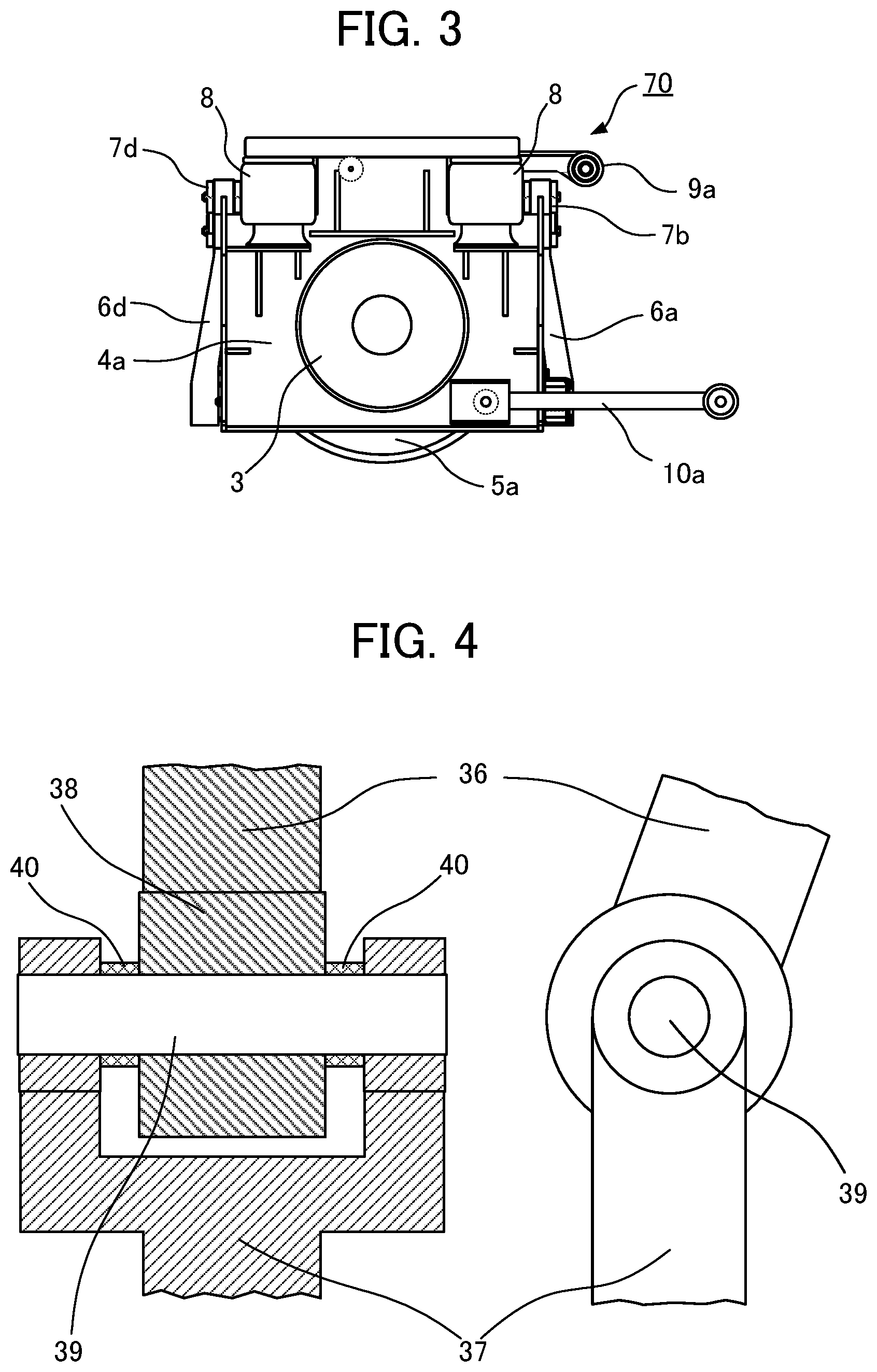
FIG. 3 is a drawing illustrating the vehicle wheel support device according to Embodiment 1 when the vehicle wheel support device is viewed from a lateral side of the vehicle;
FIG. 4 is a drawing illustrating a structure for pivotally joining components to each other;
FIG. 5 is a cross-sectional view illustrating a structure for supporting wheels of the vehicle wheel support device according to Embodiment 1;
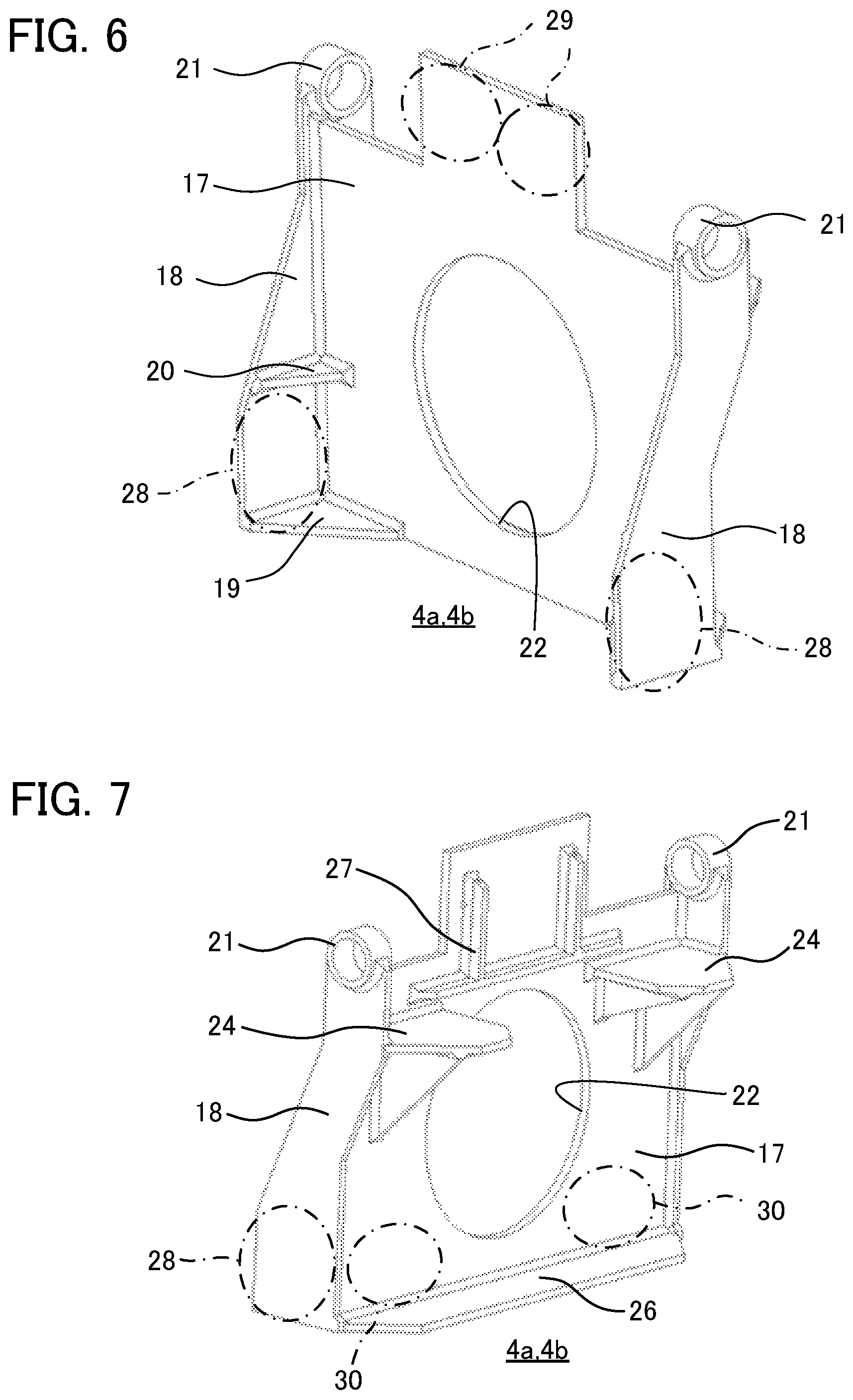
FIG. 6 is a perspective view illustrating a support frame of the vehicle wheel support device according to Embodiment 1 when the support frame is viewed from the side on which a wheel is attached;
FIG. 7 is a perspective view illustrating the support frame of the vehicle wheel support device according to Embodiment 1 when the support frame is viewed from the side on which a driving motor is attached;
FIG. 8 is a schematic view illustrating a link mechanism of the vehicle wheel support device according to Embodiment 1;
FIG. 9 is a drawing illustrating definitions of lengths of each links and a bending angle of an L-shaped link included in the link mechanism according to Embodiment 1;
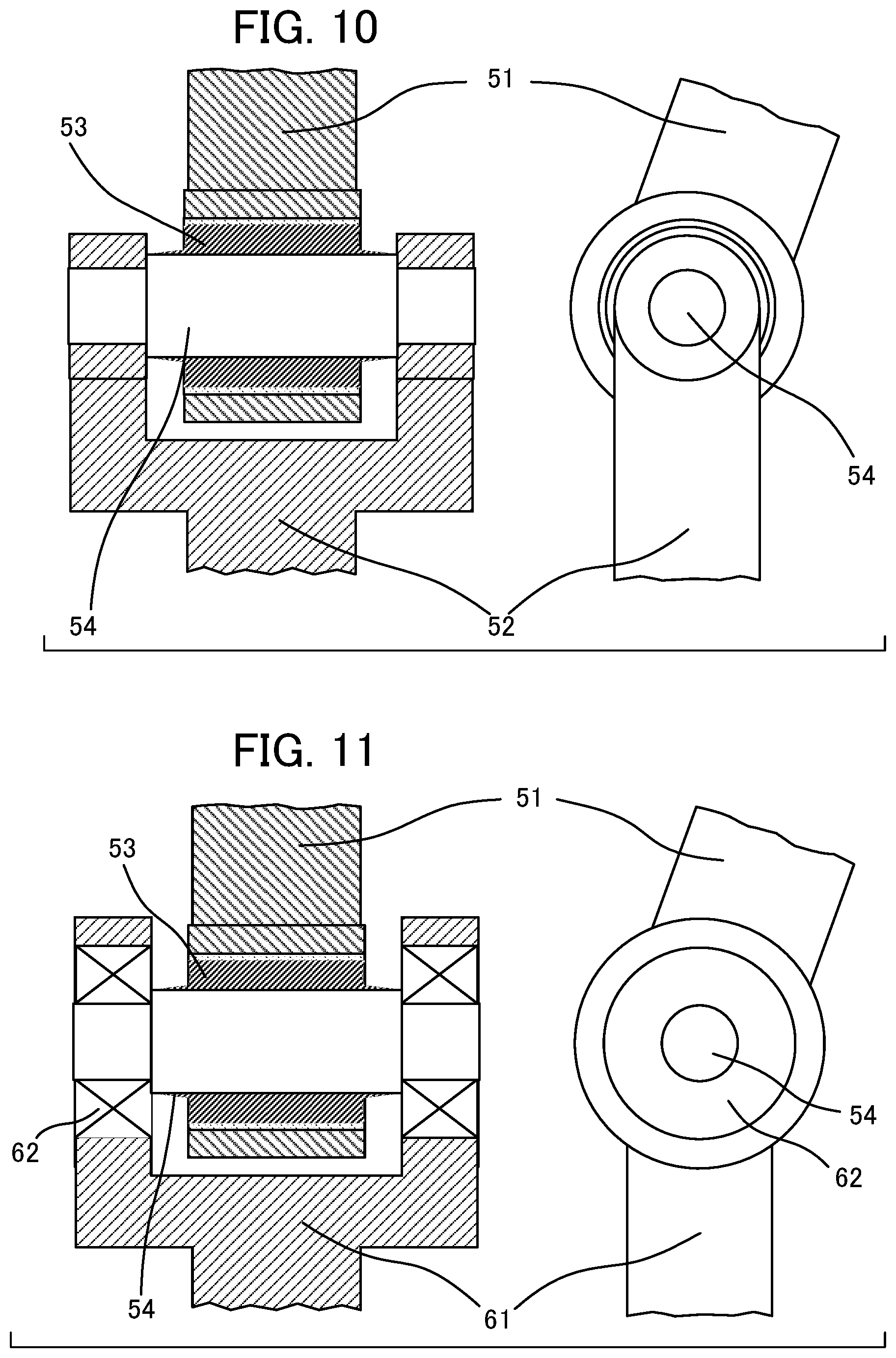
FIG. 10 is a drawing illustrating a linkage for a vehicle wheel support device according to Embodiment 2 of the present disclosure;
FIG. 11 is a drawing illustrating a linkage for a vehicle wheel support device according to Embodiment 3 of the present disclosure; and
FIG. 12 is a side view illustrating a vehicle using a vehicle wheel support device according to an embodiment of the present disclosure.
DESCRIPTION OF EMBODIMENTS
Embodiments of the present disclosure are described in detail hereinafter with reference to drawings. Components that are the same or equivalent are assigned the same reference signs throughout the drawings. Also, in order to avoid complication of the figures and to facilitate understanding, there are cases in which bolts, nuts, holes through which bolts are passed, and the like are omitted from the figures.
Embodiment 1
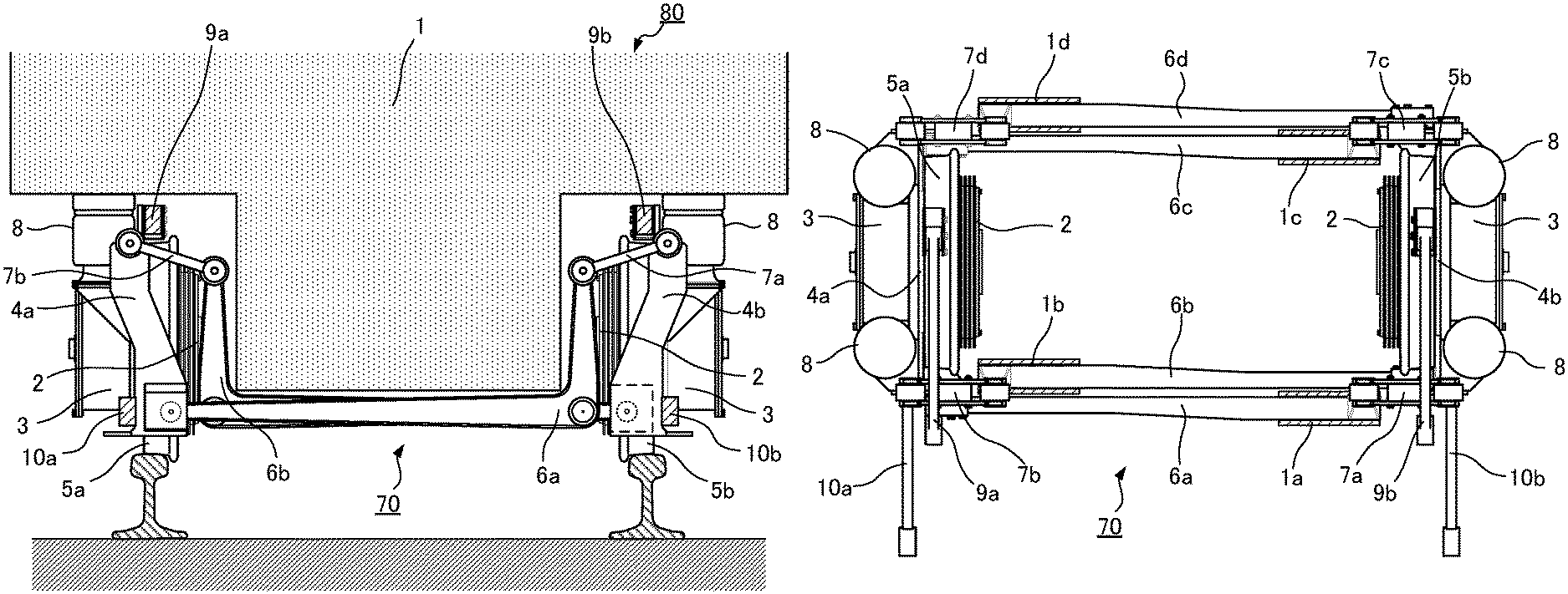
FIG. 1 is a drawing illustrating a whole structure of a vehicle wheel support device according to Embodiment 1 of the present disclosure when the vehicle wheel support device is viewed from the front side of a vehicle body of a vehicle. FIG. 2 is a drawing illustrating the vehicle wheel support device according to Embodiment 1 when the vehicle wheel support device is viewed from above. FIG. 3 is a drawing illustrating the vehicle wheel support device according to Embodiment 1 when the vehicle wheel support device is viewed from a lateral side of the vehicle. Rails and a vehicle body 1 of a vehicle 80 are omitted from FIGS. 2 and 3.
A vehicle wheel support device 70 according to Embodiment 1 of the present disclosure is used for the vehicle running on a railroad track including two rails laid parallel to each other. In the specification, terms related to the railroad track are defined as follows: a railroad track plane is defined as a plane that touches upper surfaces of the two rails; a vertical direction is defined as a direction perpendicular to the railroad track plane; front-rear direction is defined as a direction parallel to a traveling direction of the vehicle running on the railroad track; and a lateral direction is defined as a direction parallel to the railroad track plane and orthogonal to the traveling direction of the vehicle.
The vehicle wheel support device 70 according to Embodiment 1 includes a support frame 4a as a first support frame and a support frame 4b as a second support frame, and the support frames 4a and 4b rotatably support a wheel 5a as a first wheel and a wheel 5b as a second wheel in such a manner that: the wheels 5a and 5b face each other in the lateral direction; and the wheels 5a can roll on one of the two rails and the wheel 5b can roll on the other of the two rails. Also, the support frames 4a and 4b support the vehicle body 1 of the vehicle 80 via a suspension system 8. The support frames 4a and 4b respectively support one wheel 5a and one wheel 5b, and the support frames 4a and 4b are separated from each other with respect to the lateral direction. Four sets of a L-shaped link and a linear link are used with respect to displacements of the two support frames 4a and 4b relative to the vehicle body 1 in the traverse direction of the vehicle. The vehicle wheel support device 70 transmits forces between the vehicle body 1 and the supports frames 4a and 4b using four traction links, the directions of the forces being the front-rear directions of the vehicle.
A planetary gear device 2 and a driving motor 3 are fixed to each of the support frames 4a and 4b and are coaxial with the respective wheel 5a or 5b. A rotary shaft of the driving motor 3 is joined to an input shaft of the planetary gear device 2, and an output shaft of the planetary gear device 2 is joined to the wheel 5a or 5b. The wheels 5a and 5b are rotated by driving forces of the driving motors 3.
The support frame 4a is arranged farther from the rail thereof than the wheel 5a and supports the wheel 5a in such a manner that the wheel 5a can roll on the rail thereof, and the support frame 4b is arranged farther from the rail thereof than the wheel 5b and supports the wheel 5b in such a manner that the wheel 5b can roll on the rail thereof. L-shaped links 6a, 6b, 6c and 6d are respectively supported by L-shaped link-supporting portions 1a, 1b, 1c and 1d of the vehicle body in such a manner that the L-shaped links 6a, 6b, 6c and 6d can respectively pivot about shafts that are located in respective middle bending portions of the L-shaped links 6a, 6b, 6c and 6d and that run in the front-rear direction. The L-shaped link-supporting portions 1a, 1b, 1c and 1d are omitted from FIG. 1. Lower ends of the L-shaped links 6a, 6b, 6c and 6d are pivotally joined to the support frames 4a and 4b and are positioned below central axes of the wheels 5a and 5b, and upper ends of the L-shaped links 6a, 6b, 6c and 6d are pivotally joined to ends of support links 7a, 7b, 7c and 7d. The other ends of the support links 7a, 7b, 7c and 7d are pivotally joined to the support frames 4a and 4b and are positioned above the central axes of the wheels 5a and 5b. Additionally, upper traction links 9a and 9b are pivotally joined to the support frames 4a and 4b, and lower traction links 10a and 10b are respectively pivotally joined to the support frames 4a and 4b. The vehicle wheel support device 70 is configured in the above-described manner. A structure of the vehicle wheel support device 70 for supporting the support frames 4a and 4b is described below in detail.
The L-shaped link 6a as a first L-shaped link is joined to the support frame 4a below the central axis of the wheel 5a and forward of the central axis of the wheel 5a with respect to the front-rear direction in such a manner that the L-shaped link 6a can pivot about a shaft running in the front-rear direction. Also, the L-shaped link 6a is supported by the L-shaped link-supporting portion 1a of the vehicle body 1 below the central axis of the wheel 5b and forward of the central axis of the wheel 5b with respect to the front-rear direction on the wheel 5b-side with respect to the center line between the two rails in such a manner that the L-shaped link 6a can pivot about a shaft running in the front-rear direction. The L-shaped link 6b as a second L-shaped link is joined to the support frame 4b below the central axis of the wheel 5b and forward of the central axis of the wheel 5b with respect to the front-rear direction in such a manner that the L-shaped link 6b can pivot about a shaft running in the front-rear direction. Also, the L-shaped link 6b is supported by the L-shaped link-supporting portion 1b of the vehicle body 1 below the central axis of the wheel 5a and forward of the central axis of the wheel 5a with respect to the front-rear direction on the wheel 5a-side with respect to the center line between the two rails in such a manner that the L-shaped link 6b can pivot about a shaft running in the front-rear direction. The L-shaped link 6c as a third L-shaped link is joined to the support frame 4a below the central axis of the wheel 5a and reward of the central axis of the wheel 5a with respect to the front-rear direction in such a manner that the L-shaped link 6c can pivot about a shaft running in the front-rear direction. Also, the L-shaped link 6c is supported by the L-shaped link-supporting portion 1c of the vehicle body 1 below the central axis of the wheel 5b and reward of the central axis of the wheel 5b with respect to the front-rear direction on the wheel 5b-side with respect to the center line between the two rails in such a manner that the L-shaped link 6c can pivot about a shaft running in the front-rear direction. The L-shaped link 6d as a fourth L-shaped link is joined to the support frame 4b below the central axis of the wheel 5b and reward of the central axis of the wheel 5b with respect to the front-rear direction in such a manner that the L-shaped link 6d can pivot about a shaft running in the front-rear direction. Also, the L-shaped link 6d is supported by the L-shaped link-supporting portion 1d of the vehicle body 1 below the central axis of the wheel 5a and reward of the central axis of the wheel 5a with respect to the front-rear direction on the wheel 5a-side with respect to the center line between the two rails in such a manner that the L-shaped link 6d can pivot about a shaft running in the front-rear direction.
The support link 7a that is a first support link extending from the support frame 4b toward the wheel 5a-side is joined, pivotally about a shaft running in the front-rear direction, to the support frame 4b above the central axis of the wheel 5b and forward of the central axis of the wheel 5b with respect to the front-rear direction. The support link 7b that is a second support link extending from the support frame 4a toward the wheel 5b-side is joined, pivotally about a shaft running in the front-rear direction, to the support frame 4a above the central axis of the wheel 5a and forward of the central axis of the wheel 5a with respect to the front-rear direction. The support link 7c that is a third support link extending from the support frame 4b toward the wheel 5a-side is joined, pivotally about a shaft running in the front-rear direction, to the support frame 4b above the central axis of the wheel 5b and reward of the central axis of the wheel 5b with respect to the front-rear direction. The support link 7d that is a fourth support link extending from the support frame 4a toward the wheel 5b-side is joined, pivotally about a shaft running in the front-rear direction, to the support frame 4a above the central axis of the wheel 5a and reward of the central axis of the wheel 5a with respect to the front-rear direction.
The lower traction link 10a that is a first lower traction link extending in the front-rear direction is joined, pivotally about a shaft running in the lateral direction, to the support frame 4a below the central axis of the wheel 5a in such a manner that the lower traction link 10a can pivot. Also, the lower traction link 10a is supported by the vehicle body 1 pivotally about a shaft running in the lateral direction. The lower traction link 10b that is a second lower traction link extending in the front-rear direction is joined, pivotally about a shaft running in the lateral direction, to the support frame 4b below the central axis of the wheel 5b. Also, the lower traction link 10b is supported by the vehicle body 1 pivotally about a shaft running in the lateral direction. The upper traction link 9a that is a first upper traction link extending in the front-rear direction is joined, pivotally about a shaft running in the lateral direction, to the support frame 4a above the central axis of the wheel 5a. Also, the upper traction link 9a is supported by the vehicle body 1 pivotally about a shaft running in the lateral direction. The upper traction link 9b that is a second upper traction link extending in the front-rear direction is joined, pivotally about a shaft running in the lateral direction, to the support frame 4b above the central axis of the wheel 5b. Also, the upper traction link 9b is supported by the vehicle body 1 pivotally about a shaft running in the lateral direction. Portions of the vehicle body 1 by which the lower traction links 10a and 10b and the upper traction links 9a and 9b are supported are not illustrated in the drawings.
The L-shaped link 6a is joined, pivotally about a shaft running in the front-rear direction, to the support link 7a above the central axis of the wheel 5b and forward of the central axis of the wheel 5b with respect to the front-rear direction. The L-shaped link 6b is joined, pivotally about a shaft running in the front-rear direction, to the support link 7b above the central axis of the wheel 5a and forward of the central axis of the wheel 5a with respect to the front-rear direction. The L-shaped link 6c is joined, pivotally about a shaft running in the front-rear direction, to the support link 7c above the central axis of the wheel 5b and reward of the central axis of the wheel 5b with respect to the front-rear direction. The L-shaped link 6d is joined, pivotally about a shaft running in the front-rear direction, to the support link 7d above the central axis of the wheel 5a and reward of the central axis of the wheel 5a with respect to the front-rear direction.
In Embodiment 1, the L-shaped links 6a and 6c are similar to each other in shape. One of the L-shaped links 6a and 6c is arranged forward of the wheels 5a and 5b and the other of the L-shaped links 6a and 6c is arranged reward of the wheels 5a and 5b. The L-shaped links 6b and 6d are similar to each other in shape. One of the L-shaped links 6b and 6d is arranged forward of the wheels 5a and 5b and the other of the L-shaped links 6b and 6d is arranged reward of the wheels 5a and 5b. Moreover, in Embodiment 1, the L-shaped links 6a, 6b, 6c and 6d are similar to one another in shape.
FIG. 4 is a drawing illustrating a structure for pivotally joining components to each other. As illustrated in FIG. 4, the pivot junction for pivotally joining components to each other generally has a pin joint structure in which a cylindrical pin 39 is inserted into a tubular element 38 that is arranged at an end of one link 36 playing the role of a support, the pin 39 is supported by another link 37, the tubular element 38 is kept at a fixed position in an axial direction by spacers 40, and the tubular element 38, by using a lubricant agent such as grease, can pivot about the pin 39.
FIG. 5 is a cross-sectional view illustrating a structure for supporting wheels of the vehicle wheel support device according to Embodiment 1. The support frames 4a and 4b of the vehicle wheel support device 70 are symmetrical relative to each other. Therefore structural features of one support frame 4a are described below, with parentheses surrounding the reference numerals of components related to the other support frame 4b. FIG. 5 illustrates a structure for pivotally supporting the wheels 5a (5b) by the support frame 4a (4b). A fixing ring 14 is fixed to the support frame 4a (4b) by fastening a portion on the large-diameter side of the fixing ring 14 by fixing ring-fastening bolts 16. An inner bearing tube 12 is fixed to a portion on the small-diameter side of the fixing ring 14 by inner tube-fastening bolts 15. A bearing 13 is fitted around an outer radial periphery of the inner bearing tube 12. An outer bearing tube 11 is fitted around an outer radial periphery of the bearing 13 and the outer bearing tube 11 can rotate around the inner bearing tube 12. The wheel 5a (5b) is fitted around an outer radial periphery of the outer bearing tube 11 in such a manner that the wheel 5a (5b) cannot rotate on the outer bearing tube 11. The inner bearing tube 12, the bearing 13, the outer bearing tube 11 and the wheel 5a (5b) are concentric with one another and the wheel 5a (5b) is supported in such a manner that the wheel 5a (5b) can rotate relative to the support frame 4a (4b).
FIG. 6 is a perspective view illustrating a support frame of the vehicle wheel support device according to Embodiment 1 when the support frame is viewed from the side on which a wheel is attached. FIG. 7 is a perspective view illustrating the support frame of the vehicle wheel support device according to Embodiment 1 when the support frame is viewed from the side on which a driving motor is attached. The support frame 4a (4b) includes: a support frame main plate 17 for immovably supporting the planetary gear device 2 and the driving motor 3; and support frame side plates 18 that are arranged on the both sides of the support frame main plate 17, that are perpendicular to the support frame main plate 17 and that are integrated with the support frame main plate 17, and the support frame 4a (4b) is shaped like the letter "H". A fitting hole 22 enabling positioning of the fixing ring 14 is formed on the central portion of the support frame main plate 17. The fixing ring 14 illustrated in FIG. 5 is fitted into the fitting hole 22 and is fixed to the support frame 4a (4b), for example, by fastening the fixing ring 14 by the plurality of fixing ring-fastening bolts 16.
The support link 7b (7a) and the support link 7d (7c) are pivotally joined to support frame upper portion-supporting portions 21 illustrated in FIG. 6. The L-shaped link 6a (6b) and the L-shaped link 6c (6d) are pivotally joined to support frame lower portion-supporting portions 28.
The support frame 4a (4b) is subjected axially to a lateral load from the wheel 5a (5b) when the vehicle travels. Therefore, reinforcing plates 19 and 20 are fixed to a portion of the support frame 4a (4b) on the side on which the wheel 5a (5b) is attached and reinforcing plates 26 and 27 are fixed to a portion of the support frame 4a (4b) on the side on which the driving motor 3 is attached. Mounting boards 24 on which the suspension systems 8 are mounted are fixed to the support frame 4a (4b) on the side on which the driving motor 3 is attached. The vehicle body 1 is supported via the suspension systems 8 mounted on the mounting boards 24. The suspension systems 8 are, for example, air suspensions. For example, the air suspensions are fixed to the support frame 4a (4b) by passing bolts into bolt holes formed on the mounting boards 24 and by fastening the bolts from the lower side. Examples of the suspension systems 8 that can be used for the present disclosure include not only the air suspension but also a laminated leaf spring and a combination of a coil spring and a damper.
For the movement of the support frame 4a (4b) relative to the vehicle body 1 in the front-rear direction of the vehicle, the upper traction link 9a (9b) and the lower traction link 10a (10b) are each attached to the support frame 4a (4b) that is arranged in the lateral direction. One end of the upper traction link 9a (9b) is joined, pivotally about a shaft running in the lateral direction, to one of two upper traction link-supporting portions 29. The other end of the upper traction link 9a (9b) is joined, pivotally about a shaft running in the lateral direction, to the vehicle body 1. One end of the lower traction link 10a (10b) is joined, pivotally about a shaft running in the lateral direction, to one of two lower traction link-supporting portions 30 illustrated in FIG. 7. The other end of the lower traction link 10a, 10b is joined, pivotally about a shaft running in the lateral direction, to the vehicle body 1. Therefore, a traction force occurring in the wheel 5a (5b) can be transmitted to the vehicle body 1. Additionally, a braking force can be transmitted to the vehicle body 1-side when the vehicle is braked.
As illustrated in FIGS. 2 and 3, in Embodiment 1, the upper traction links 9a and 9b and the lower traction links 10a and 10b extend, in the same direction, from the shafts joined to the support frames 4a and 4b, and are pivotally joined to the vehicle body 1. Alternatively, the upper traction links 9a and 9b and the lower traction links 10a and 10b may be pivotally joined to the vehicle body 1 with the upper traction links 9a and 9b extending from the support frames 4a and 4b in one direction and with the lower traction links 10a and 10b extending from the support frames 4a and 4b in the direction opposite to the direction of the upper traction links 9a and 9b extending from the support frames 4a and 4b. As illustrated in FIGS. 6 and 7, the support frame 4a (4b) is provided with the two upper traction link-supporting portions 29 and the two lower traction-supporting links 30, and thus when the direction of a traction link joined to the vehicle body 1 is changed, the configuration of the present disclosure can be easily changed by changing a position of the traction link attached to a traction link-supporting portion.
Next, a structure for supporting the support frames 4a and 4b from the vehicle body 1-side is described. FIG. 8 is a schematic view illustrating a link mechanism of the vehicle wheel support device according to Embodiment 1. FIG. 8 schematically illustrates the relation among the support frames 4a and 4b, the L-shaped links 6a and 6b and the support links 7a and 7b that are illustrated in FIG. 1. Regarding movements of the L-shaped links and the support links in the plane orthogonal to the front-rear direction, the behavior of the L-shaped links 6a and 6b and the behavior of the support links 7a and 7b are similar to the behavior of the L-shaped links 6c and 6d and the behavior of the support links 7c and 7d.
The L-shaped links 6a and 6b are arranged between the lateral support frames 4a and 4b, and the middle bending portions of the L-shaped links 6a and 6b are provided with L-shaped link-supporting shafts 31a and 31b that are supported pivotally around axes running from the vehicle body 1 in the front-rear direction. One end of the L-shaped link 6a extending from the L-shaped link-supporting shaft 31a in the lateral direction is provided with a support frame lower portion joining shaft 32a that is joined, pivotally about an axis running in the front-rear direction, to the support frame lower portion-supporting portion 28 of the support frame 4a. One end of the L-shaped link 6b extending from the L-shaped link-supporting shaft 31b in the lateral direction is provided with a support frame lower portion joining shaft 32b that is joined, pivotally about an axis running in the front-rear direction, to the support frame lower portion-supporting portion 28 of the support frame 4b. The other end of the L-shaped link 6a extending from the L-shaped link-supporting shaft 31a in the vertical direction is provided with a link-jointing shaft 33a that is joined, pivotally about an axis running in the front-rear direction, to one end of the support link 7a. The other end of the L-shaped link 6b extending from the L-shaped link-supporting shaft 31b in the vertical direction is provided with a link-jointing shaft 33b that is joined, pivotally about an axis running in the front-rear direction, to one end of the support link 7b. The other ends of the support links 7a and 7b are respectively provided with support frame upper portion-joining shafts 34a and 34b that are respectively joined, pivotally about axes running in the front-rear direction, to the support frame upper portion-supporting portions 21 of the support frames 4a and 4b. The L-shaped link 6a and the support link 7a are joined, pivotally about an axis running in the front-rear direction, to the link-jointing shaft 33a. The L-shaped link 6b and the support link 7b are joined, pivotally about an axis running in the front-rear direction, to the link-jointing shaft 33b. As illustrated in FIG. 2, one of two sets of these L-shaped links and support links is arranged on the front side of the support frames 4a and 4b and the other of the two sets is arranged on the rear side of the support frames 4a and 4b, thereby the support frames 4a and 4b that are arranged in the lateral direction are supported by the four sets of L-shaped link and support link in the lateral direction of the vehicle body.
When the vehicle travels on a railroad track, in addition to motion of the vehicle body 1 in the front-rear direction which is caused by acceleration of or braking of the vehicle, the vehicle body 1 is also subjected to a force in the plane orthogonal to the front-rear direction, thereby causing a displacement of the vehicle body 1 relative to the wheels 5a and 5b in the plane orthogonal to the front-rear direction. An up-and-down movement of the vehicle 1 is caused by simultaneous and samely-directed bumpy movements of both the wheels 5a and 5b relative to the vehicle body 1. For example, a downward movement of the vehicle body 1 can be regarded as simultaneous upward movements of both the wheels 5a and 5b relative to the vehicle body 1. In this case, the support frame lower portion-joining shaft 32a of the lower end of the L-shaped link 6a pivotally joined to the left-side support frame 4a moves upward in a circular arc, the center of which is the L-shaped link-supporting shaft 31a of the middle bending portion of the L-shaped link 6a. Also, the support frame lower portion-joining shaft 32b of the lower end of the L-shaped link 6b pivotally joined to the right-side support frame 4b moves upward in a circular arc, the center of which is the L-shaped link-supporting shaft 31b of the middle bending portion of the L-shaped link 6b, like the support frame lower portion-joining shaft 32a of the lower end of the L-shaped link 6a.
The link-jointing shaft 33a of the other end of the L-shaped link 6a moves to the support frame 4b-side in a circular arc, the center of which is the L-shaped link-supporting shaft 31a, in response to the above movement of the support frame lower portion-joining shaft 32a. The link-jointing shaft 33b of the other end of the L-shaped link 6b moves to the support frame 4a-side in a circular arc, the center of which is the L-shaped link-supporting shaft 31b, in response to the above movement of the support frame lower portion-joining shaft 32b. The ranges of the up-and-down movements of the wheels 5a and 5b are smaller than the distance from the support frame lower portion joining shaft 32a to the L-shaped link-supporting shaft 31a in the L-shaped link 6a and the distance from the support frame lower portion joining shaft 32b to the L-shaped link-supporting shaft 31b in the L-shaped link 6b, so that amounts of the transversely horizontal movements of the support frame lower portion-joining shafts 32a and 32b caused by the up-and down movements of the wheels 5a and 5b is extremely small.
When the wheels 5a and 5b move upward relative to the vehicle body 1, the link-jointing shafts 33a and 33b of the L-shaped links 6a and 6b move to the outside as described above. The support frame upper portion-joining shafts 34a and 34b of the support frames 4a and 4b support the link-jointing shafts 33a and 33b via the support links 7a and 7b that make angles with the horizontal. Therefore, when the movements of the link-jointing shafts 33a and 33b to the outside and the upward movements of the support frame lower portion-joining shafts 32a and 32b simultaneously occur, amounts of the transversely horizontal movements of the support frame upper portion-joining shafts 34a and 34b of the support frames 4a and 4b are small. As a result, the inclinations of the support frames 4a and 4b are nearly unchanged and thus can be maintained. Due to simultaneous upward movements of the left-side and right-side wheels 5a and 5b, the railroad track plane also move parallel with the railroad track plane keeping parallel to the central axes of the wheels 5a and 5b, and the wheels 5a and 5b move up and down with rotation planes thereof maintained nearly perpendicular to the railroad track plane.
In the case where a rolling motion of the vehicle body 1 occurs, up-and-down movements of the left-side wheel 5a relative to the vehicle body 1 are different from up-and-down movements of the right-side wheel 5b relative to the vehicle body 1. For example, in the case where the vehicle body 1 pivots about the wheel 5b to slant to the wheel 5a-side, up-and-down movements of the right-side wheel 5b relative to the vehicle body 1 do not occur, and only the left-side wheel 5a can be regarded as moving upward relative to the vehicle body 1. In this case, neither the support frame lower portion-joining shaft 32b arranged in the lower portion of the right-side support frame 4b nor the link-jointing shaft 33b of the other end of the L-shaped link 6b moves.
The left-side support frame 4a moves upward, the support frame lower portion joining shaft 32a moves upward in an circular arc, the center of which is the L-shaped link-supporting shaft 31a of the L-shaped link 6a, and the link-jointing shaft 33a of the other end of the L-shaped link 6a moves to the right side. The amounts of the up-and-down movements of the support frame lower portion-joining shaft 32a are extremely smaller compared to the distance from the support frame lower portion-joining shaft 32a of the L-shaped link 6a to the L-shaped link-supporting shaft 31a of the L-shaped link 6a, and thus an amount of transversely horizontal movement of the support frame lower portion joining shaft 32a is small even though the support frame lower portion-joining shaft 32a moves in a circular arc. In the left-side support frame 4a, the support frame lower portion-joining shaft 32a moves nearly upward, and the inclination angle of the support link 7b causes the support frame upper portion-joining shaft 34a to pivot about the link-jointing shaft 33b that is immovable, thereby causing both upward and rightward movements of the support frame upper portion-joining shaft 34a. As a result, the support frame 4a inclines to the right side.
However, in the right-side support frame 4b, the support frame lower portion-joining shaft 32b arranged in the lower portion of the support frame 4b does not move but the link-jointing shaft 33a of the L-shaped link 6a moves to the right side. Therefore, the support frame upper portion joining shaft 34b of the support frame 4b is moved to the right side by the support link 7a. As a result, the support frame 4b also inclines to the right side. Although the up-and down movements of the right-side wheel 5b relative to the vehicle body 1 does not occur, the left-side wheel 5a moves upward, thereby the railroad track plane changes from a state in which the railroad track plane is in a horizontal position to a state in which the railroad track plane inclines to the right side, and both the left-side support frame 4a and the right-side support frame 4b incline to the right side. Therefore, also in this case, both the planes of rotation of the wheels 5a and 5b are kept nearly perpendicular to the railroad track plane.
Various movements of the vehicle body 1 including the up-and-down movements thereof and the rolling motion thereof can be expressed by the sum of the above-described simultaneous up-and-down movements of the wheels 5a and 5b and the above-described up-and-down movements of only one of the wheels 5a and 5b. As described above, both in the case of occurrence of simultaneous the up-and-down movements of the wheels 5a and 5b and in the case of occurrence of the up-and-down movements of only one of the wheels 5a and 5b, both the planes of rotation of the wheels 5a and 5b can be kept nearly perpendicular to the railroad track plane, and thus even when these movements are combined, both the planes of rotation of the wheels 5a and 5b can be kept nearly perpendicular to the railroad track plane.
As described above, the vehicle wheel support device 70 of Embodiment 1 has an effect enabling both the wheels 5a and 5b to be maintained nearly perpendicularly to the railroad track plane regardless of how the vehicle body 1 moves. However, a degree of a change in inclination angles of the wheels 5a and 5b with the railroad track plane and a degree of a change in distance between the wheels 5a and 5b vary in accordance with setting of the distance between the L-shaped link-supporting shafts 31a and 31b, the distance from the L-shaped link-supporting shaft 31a to the support frame lower portion-joining shaft 32a, the distance from the L-shaped link-supporting shaft 31b to the support frame lower portion joining shaft 32b, the distance from the L-shaped link-supporting shaft 31a to the link-jointing shaft 33a, the distance from the L-shaped link-supporting shaft 31b to the link-jointing shaft 33b, the distance from the link-jointing shaft 33a to the support frame upper portion-joining shaft 34a, the distance from the link-jointing shaft 33b to the support frame upper portion-joining shaft 34b, the distance from the support frame lower portion-joining shaft 32a to the support frame upper portion joining shaft 34a, and the distance from the support frame lower portion-joining shaft 32b to the support frame upper portion joining shaft 34b. FIG. 9 is a drawing illustrating definitions of lengths of each links and a bending angle of an L-shaped link included in the link mechanism according to Embodiment 1.
The distance between the L-shaped link-supporting shafts 31a and 31b is expressed by the symbol "L1", the distance from the L-shaped link-supporting shaft 31a of the L-shaped link 6a to the support frame lower portion-joining shaft 32a is expressed by the symbol "L2", the distance from the L-shaped link-supporting shaft 31a of the L-shaped link 6a to the link-jointing shaft 33a is expressed by the symbol "L3", the distance from the link-jointing shaft 33a of the support link 7a to the support frame upper portion-joining shaft 34a is expressed by the symbol "L4", the distance from the support frame lower portion-joining shaft 32a of the support frame 4a to the support frame upper portion-joining shaft 34a is expressed by the symbol "L5", and an angle between the shortest line segment from the support frame lower portion-joining shaft 32a of the L-shaped link 6a to the L-shaped link-supporting shaft 31a of the L-shaped link 6a and the shortest line segment from the L-shaped link-supporting shaft 31a of the L-shaped link 6a to the link-jointing shaft 33a of the L-shaped link 6a is expressed by the symbol, ".phi.". The distances between the corresponding pivot junction of the L-shaped links 6b, 6c and 6d and the angles between the shortest line segments between the corresponding pivot junction of the L-shaped links 6b, 6c and 6d are respectively the same as the distances between the above pivot junction of the L-shaped link 6a and the angle between the shortest line segments between the above pivot junction of the L-shaped link 6a, and the distances between the corresponding pivot junction of the support links 7b, 7c and 7d are the same as the distances between the above pivot junction of the support link 7a. Therefore, the distances between the corresponding pivot junction of the L-shaped links 6b, 6c and 6d and the support links 7b, 7c and 7d and the angles between the shortest segments between the corresponding pivot junction of the L-shaped links 6b, 6c and 6d are also respectively expressed by the symbols, "L1" to "L5" and ".phi.".
For a combination of the distances L2, L3, L4 and L5 and the angle .phi. when the distance L1 between the L-shaped link-supporting shafts 31a and 31b is set in accordance with a track gauge of the railroad track on which a vehicle provided with the vehicle wheel support device 70 travels, numerical calculations can be performed to calculate a change in a distance between the wheels 5a and 5b that is a wheel distance in the case where the up-and-down movements of wheels 5a and 5b in the same direction or in opposite directions occur and a change in angles with the railroad track plane which the wheels 5a and 5b make. For combinations of values obtained by varying the distances L2 to L5 and the angle .phi. within possible ranges of the distances L2 to L5 and the angle .phi. and under constraint conditions thereof, a change in distance between the wheels 5a and 5b due to up-and-down movements of the wheels 5a and 5b and a change in angles with the railroad track plane which the wheels 5a and 5b make are calculated, and the combination of values of the distances L2 to L5 and the angle .phi. is found for which the calculated change in distance between the wheels 5a and 5b and the calculated change in angles with the railroad track plane have the minimum values. Therefore, the vehicle wheel support device 70 can be made by forming the support frames 4a and 4b, the L-shaped links 6a, 6b, 6c and 6d and support links 7a, 7b, 7c and 7d that can achieve the set value of the wheel distance L1 and the values of the distances L2 to L5 and the angle .phi. at which the change in wheel distance due to up-and-down movements of the wheels 5a and 5b and the change in angles with the railroad track vehicle which the wheels 5a and 5b make have the minimum values.
The L-shaped link-supporting shafts 31a and 31b of the L-shaped links 6a and 6b are supported by the vehicle body 1 so as not to move relative to the vehicle body 1 in the vertical direction. Depending on the matter of setting the length of the L-shaped link 6a between the L-shaped link-supporting shaft 31a and the support frame lower portion-joining shaft 32a and the length of the L-shaped link 6b between the L-shaped link-supporting shaft 31b and the support frame lower portion joining shaft 32b, a vertical distance from the railroad track plane to a floor plane of the vehicle body in a low floor portion of the vehicle body between the wheels 5a and 5b is the sum of the minimum necessary vertical distance from the railroad track plane to the bottom of the vehicle body, a minimum necessary space for the L-shaped link-supporting shafts 31a and 31b of the L-shaped links 6a and 6b, and the thickness of the low floor portion of the vehicle body. Unlike conventional configurations used in the prior art, the configuration of the vehicle wheel support device 70 according to Embodiment 1 does not require any space necessary for relative up-and-down movements of the bogie frame supporting the wheels 5a and 5b relative to the vehicle body and thus makes possible achievement of a lower vertical distance between the floor plane of the vehicle body and the railroad track plane compared with vehicles using the conventional techniques.
As described above, in the vehicle wheel support device 70 according Embodiment 1, the support frames 4a and 4b rotatably supporting the wheels 5a and 5b are respectively arranged to the outside of the wheels 5a and 5b, the L-shaped links 6a, 6b, 6c and 6d are pivotally supported by the vehicle body 1 via the middle bending portions of the L-shaped links 6a, 6b, 6c and 6d, the L-shaped links 6a, 6b, 6c and 6d are pivotally joined to the support frames 4a and 4b via the support frame lower portion joining shafts 32a and 32b and to one ends of the support links 7a, 7b, 7c and 7d via the link-jointing shafts 33a and 33b. The other ends of the support links 7a, 7b, 7c and 7d are pivotally joined to the support frame upper portion-joining shafts 34a and 34b of the support frames 4a and 4b. The vehicle wheel support device 70 used for the vehicle 80 is configured by pivotally joining the upper traction link 9a and the lower traction links 10a to the support frame 4a and pivotally joining the upper traction link 9b and the lower traction links 10b to the support frame 4b. Therefore, in the vehicle wheel support device 70 according to Embodiment 1, defining distances between pivot junctions in accordance with selected values of the distance between the L-shaped link-supporting shafts 31a and 31b of the L-shaped links 6a and 6b enables a remarkable reduction in a change in distance between the wheels 5a and 5b due to up-and-down movements of the vehicle body 1 and a change in angles with the railroad track plane which the wheels 5a and 5b make. Therefore, while maintaining conditions similar to those of a generally-used railroad vehicle using the wheels integrated with the wheel shaft, upsprung mass of the vehicle can be reduced and a floor plane of the vehicle body between the wheels can be made to become close to the railroad track plane.
In FIG. 1 illustrating the vehicle wheel support device 70 according to Embodiment 1, the L-shaped link 6a overlaps the L-shaped link 6c, the L-shaped link 6b overlaps the L-shaped link 6d, the support link 7a overlaps the support link 7c, and the support link 7b overlaps the support link 7d. That is to say, in a state in which the wheels 5a and 5b are motionless on the horizontally-disposed railroad track plane, a position of a shaft of the L-shaped link 6a joining the L-shaped link 6a to the support frame 4a projected on a plane orthogonal to the front-rear direction matches a position of a shaft of the L-shaped link 6c joining the L-shaped link 6c to the support frame 4a projected on the plane orthogonal to the front-rear direction, a position of a shaft of the L-shaped link 6b joining the L-shaped link 6b to the support frame 4b projected on the plane orthogonal to the front-rear direction matches a position of a shaft of the L-shaped link 6d joining the L-shaped link 6d to the support frame 4b projected on the plane orthogonal to the front-rear direction, a position of a shaft of the L-shaped link 6a joining the L-shaped link 6a to the L-shaped link-supporting portion 1a projected on the plane orthogonal to the front-rear direction matches a position of a shaft of the L-shaped link 6c joining the L-shaped link 6c to the L-shaped link-supporting portion 1c projected on the plane orthogonal to the front-rear direction, a position of a shaft of the L-shaped link 6b joining the L-shaped link 6b to the L-shaped link-supporting portion 1b projected on the plane orthogonal to the front-rear direction matches a position of a shaft of the L-shaped link 6d joining the L-shaped link 6d to the L-shaped link-supporting portion 1d projected on the plane orthogonal to the front-rear direction, a position of the shaft of the L-shaped link 6a joining the L-shaped link 6a to the support link 7a projected on the plane orthogonal to the front-rear direction matches a position of a shaft of the L-shaped link 6c joining the L-shaped link 6c to the support link 7c projected on the plane orthogonal to the front-rear direction, a position of the shaft of the L-shaped link 6b joining the L-shaped link 6b to the support link 7b projected on the plane orthogonal to the front-rear direction matches a position of the shaft of the L-shaped link 6d joining the L-shaped link 6d to the support link 7d projected on the plane orthogonal to the front-rear direction, a position of a shaft of the support link 7a joining the support link 7a to the support frame 4b projected on the plane orthogonal to the front-rear direction matches a position of a shaft of the support link 7c joining the support link 7c to the support frame 4b and projected on the plane orthogonal to the front-rear direction, and a position of a shaft of the support link 7b joining the support link 7b to the support frame 4a projected on the plane orthogonal to the front-rear direction matches a position of a shaft of the support link 7d joining the support link 7d to the support frame 4a projected on the plane orthogonal to the front-rear direction.
Also, in FIG. 1, the L-shaped links 6a and 6b are arranged in a bilaterally symmetrical manner, the L-shaped links 6c and 6d are arranged in a bilaterally symmetrical manner, the support links 7a and 7b are arranged in a bilaterally symmetrical manner, and the support links 7c and 7d are arranged in a bilaterally symmetrical manner. That is to say, in the state in which the wheels 5a and 5b are motionless on the horizontally-disposed railroad track plane, the position of the shaft of the L-shaped link 6a joining the L-shaped link 6a to the support frame 4a projected on the plane orthogonal to the front-rear direction and the position of the shaft of the L-shaped link 6b joining the L-shaped link 6b to the support frame 4b projected on the plane orthogonal to the front-rear direction are symmetric with respect to a plane that runs along the center line between the two rails and that is perpendicular to the railroad track plane, the position of the shaft of the L-shaped link 6a joining the L-shaped link 6a to the L-shaped link-supporting portion 1a projected on the plane orthogonal to the front-rear direction and the position of the shaft of the L-shaped link 6b joining the L-shaped link 6b to the L-shaped link-supporting portion 1b projected on the plane orthogonal to the front-rear direction are symmetric with respect to the plane that runs along the center line between the two rails and that is perpendicular to the railroad track plane, the position of the shaft of the L-shaped link 6a joining the L-shaped link 6a to the support link 7a projected on the plane orthogonal to the front-rear direction and the position of the shaft of the L-shaped link 6b joining the L-shaped link 6b to the support link 7b projected on the plane orthogonal to the front-rear direction are symmetric with respect to the plane that runs along the center line between the two rails and that is perpendicular to the railroad track plane, and the position of the shaft of the support link 7a joining the support link 7a to the support frame 4b projected on the plane orthogonal to the front-rear direction and the position of the shaft of the support link 7b joining the support link 7b to the support frame 4a projected on the plane orthogonal to the front-rear direction are symmetric with respect to the plane that runs along the center line between the two rails and that is perpendicular to the railroad track plane.
In the vehicle wheel support device 70 according to Embodiment 1, as illustrated in FIGS. 1 and 2, the configuration of the L-shaped links 6a, 6b, 6c and 6d and the support links 7a, 7b, 7c and 7d has rotational symmetry with respect to an axis that passes through the central point between the wheels 5a and 5b and that is perpendicular to the railroad track plane in the state in which the wheels 5a and 5b stop on the railroad track plane that is in a horizontal state. As illustrated in FIG. 2, the configuration of the support links 7a, 7b, 7c and 7d is symmetric with respect to the plane that runs along the center line between two rails and that is perpendicular to the railroad track plane. Also, the support frame lower portion-joining shaft 32a of the support frame 4a and the support frame lower portion-joining shaft 32b of the support frame 4b are symmetric with respect to the plane that runs along the center line between the two rails and that is perpendicular to the railroad track plane.
The position of the L-shaped link 6c may be interchanged with the position of the L-shaped link 6d with respect to the front-rear direction so that configuration of the L-shaped links 6a, 6b, 6c and 6d and the support links 7a, 7b, 7c and 7d has symmetry with respect to a plane that runs along the central axes of the wheels 5a and 5b and that is orthogonal to the front-rear direction in the state in which the wheels 5a and 5b stop on the railroad track plane that is in a horizontal state.
In Embodiment 1, as illustrated in FIGS. 2 and 3, the upper traction links 9a and 9b and the lower traction links 10a and 10b are pivotally joined to the vehicle body 1 on the same side of the vehicle wheel support device 70 in the front-rear direction. Alternatively, the upper traction links 9a and 9b may be pivotally joined to the vehicle body 1 on one side of the vehicle wheel support device 70 with respect to the front-rear direction and the lower traction links 10a and 10b may be pivotally joined to the vehicle body 1 on the other side of the vehicle wheel support device 70 with respect to the front-rear direction.
In Embodiment 1, as illustrated in FIG. 2, the structures including the support frames 4a and 4b, the upper traction links 9a and 9b and the lower traction links 10a and 10b are symmetric with respect to the plane that runs along the center line between the two rails and that is perpendicular to the railroad track plane. Also, as illustrated in FIG. 3, the distance from the shaft of the upper traction link 9a joining the upper traction link 9a to the support frame 4a to a shaft of the upper traction link 9a for supporting the upper traction link 9a by the vehicle body is equal to the distance from the shaft of the lower traction link 10a joining the lower traction link 10a to the support frame 4a to a shaft of the lower traction link 10a for supporting the lower traction link 10a by the vehicle body 1, and the distance from the shaft of the upper traction link 9b joining the upper traction link 9b to the support frame 4b to a shaft of the upper traction link 9b for supporting the upper traction link 9b by the vehicle body 1 is equal to the distance from the shaft of the lower traction link 10b joining the lower traction link 10b to the support frame 4b to a shaft of the lower traction link 10b for supporting the lower traction link 10b by the vehicle body 1. Alternatively, the distance from the shaft of the upper traction link 9a joining the upper traction link 9a to the support frame 4a to the shaft of the upper traction link 9a for supporting the upper traction link 9a by the vehicle body 1 may be different from the shaft of the lower traction link 10a joining the lower traction link 10a to the support frame 4a to the shaft of the lower traction link 10a for supporting the lower traction link 10a by the vehicle body 1, and the distance from the shaft of the upper traction link 9b joining the upper traction link 9b to the support frame 4b to the shaft of the upper traction link 9b for supporting the upper traction link 9b by the vehicle body 1 may be different from the distance from the distance from the shaft of the lower traction link 10b joining the lower traction link 10b to the support frame 4b to the shaft of the lower traction link 10b for supporting the lower traction link 10b by the vehicle body 1.
Also, as illustrated in FIG. 3, the shortest line segment from the shaft of the upper traction link 9a joining the upper traction link 9a to the support frame 4a to the shaft of the upper traction link 9a for supporting the upper traction link 9a by the vehicle body 1 and the shortest line segment from the shaft of the upper traction link 9b joining the upper traction link 9b to the support frame 4b to the shaft of the upper traction link 9b for supporting the upper traction link 9b by the vehicle body 1 are parallel to the shortest segment from the shaft of the lower traction link 10a joining the lower traction link 10a to the support frame 4a to the shaft of the lower traction link 10a for supporting the lower traction link 10a by the vehicle body 1 and the shortest segment from the shaft of the lower traction link 10b joining the lower traction link 10b to the support frame 4b to the shaft of the lower traction link 10b for supporting the lower traction link 10b by the vehicle body 1. Alternatively, in the vehicle wheel support device 70 according to Embodiment 1, the upper traction links 9a and 9b and the lower traction links 10a and 10b may be arranged in such a manner that: an extended line of the shortest line segment from the shaft of the upper traction link 9a joining the upper traction link 9a to the support frame 4a to the shaft of the upper traction link 9a for supporting the upper traction link 9a by the vehicle body 1 and an extended line of the shortest line segment from the shaft of the upper traction link 9b joining the upper traction link 9b to the support frame 4b to the shaft of the upper traction link 9b for supporting the upper traction link 9b by the vehicle body 1 intersect an extended line of the shortest segment from the shaft of the lower traction link 10a joining the lower traction link 10a to the support frame 4a to the shaft of the lower traction link 10a for supporting the lower traction link 10a by the vehicle body 1 and an extended line of the shortest segment from the shaft of the lower traction link 10b joining the lower traction link 10b to the support frame 4b to the shaft of the lower traction link 10b for supporting the lower traction link 10b by the vehicle body 1; or the shortest line segment from the shaft of the upper traction link 9a joining the upper traction link 9a to the support frame 4a to the shaft of the upper traction link 9a for supporting the upper traction link 9a by the vehicle body 1 and the shortest line segment from the shaft of the upper traction link 9b joining the upper traction link 9b to the support frame 4b to the shaft of the upper traction link 9b for supporting the upper traction link 9b by the vehicle body 1 are skew to the shortest line segment from the shaft of the lower traction link 10a joining the lower traction link 10a to the support frame 4a to the shaft of the lower traction link 10a for supporting the lower traction link 10a by the vehicle body 1 and the shortest segment from the shaft of the lower traction link 10b joining the lower traction link 10b to the support frame 4b to the shaft of the lower traction link 10b for supporting the lower traction link 10b by the vehicle body 1.
Embodiment 2
FIG. 10 is a drawing illustrating a linkage for a vehicle wheel support device according to Embodiment 2 of the present disclosure. In the vehicle wheel support device 70 according to Embodiment 2, each of the pivot junctions is pivotally joined using an elastic member such as a rubber bushing instead of a simple pin joint. The other structures of the vehicle wheel support device 70 according to Embodiment 2 are similar to those of the vehicle wheel support device 70 according to Embodiment 1.
As illustrated in FIG. 10, a rubber bushing 53 is fitted into a hole formed in an end of one link 51 and a rubber bushing shaft 54 penetrating through the rubber bushing 53 is supported by the other link 52, thus forming a joint portion. The link 51 denotes one of the L-shaped links 6a, 6b, 6c and 6d, and the link 52 denotes one of the support links 7a, 7b, 7c and 7d. Although FIG. 10 illustrates the joint portion between the link 51 and the link 52, the link 51 can be also joined to the support frame lower portion-joining shaft 32a or 32b or the support frame upper portion-joining shaft 34a or 34b of the support frame 4a or 4b in a manner similar to that illustrated in FIG. 10.
In the support portion illustrated in FIG. 10, the links 51 and 52 can pivot relative to each other by elastic deformation of rubber of the rubber bushing 53. Also, there is a likelihood that the links 51 and 52 incline relative to each other in addition to relative pivot of the links 51 and 52 around the shaft. Therefore, the use of the rubber bushing 53 produces an effect of allowing an axis of the end of the link 51 to incline relative to an axis of the rubber bushing shaft 54 by elastic deformation of the elastic member. Additionally, the elastic member has an effect of absorbing an impact, thus enabling anticipation of an effect that is an ability to absorb an impact force transmitted from the railroad track plane to the vehicle body 1.
Embodiment 3
FIG. 11 is a drawing illustrating a linkage for a vehicle wheel support device according to Embodiment 3 of the present disclosure. In the vehicle wheel support device 70 according to Embodiment 3, each of the pivot junctions is pivotally joined using both a bearing and an elastic member such as a rubber bushing instead of a simple pin joint. The other structures of the vehicle wheel support device 70 according to Embodiment 3 are similar to those of the vehicle wheel support device 70 according to Embodiment 1.
As illustrated in FIG. 11, the rubber bushing 53 is fitted into a hole formed in an end of one link 51, the both ends of the rubber bushing shaft 54 penetrating through the rubber bushing 53 are fitted into bearings 62 and the bearings 62 are supported by an end of the other link 61, thus forming a joint portion. The link 51 denotes one of the L-shaped links 6a, 6b, 6c and 6d and the link 61 denotes one of the support links 7a, 7b, 7c and 7d. Although FIG. 11 illustrates the joint portion between the two links 51 and 61, the link 51 can be also joined to the support frame lower portion-joining shaft 32a or 32b or the support frame upper portion-joining shaft 34a or 34b of the support frame 4a or 4b in a manner similar to that illustrated in FIG. 11.
In Embodiment 3, the bearings 62 allow the links 51 and 61 to pivot relative to each other. The rubber bushing 53 enables relative inclinations of axes of the joint portions of the links 51 and 61 and absorption of an impact force transmitted from the railroad track plane to the vehicle body 1. Even if a pivot angle of the joint portion is relatively large, the bearings 62 enable problem-free pivoting. Additionally, anticipation is possible of an effect that is an ability to eliminate a repelling force occurring during pivoting and a frictional force occurring in the support portion.
FIG. 12 is a side view illustrating a vehicle using a vehicle wheel support device according to an embodiment of the present disclosure. The vehicle 80 illustrated in FIG. 12 includes two vehicle wheel support devices 70 that are illustrated in FIG. 3 and that are arranged on the front side and the rear side of the vehicle 80. In FIG. 12, the two vehicle wheel support devices 70 are arranged in such a manner that upper traction link 9a and the lower traction link 10a of one of the two vehicle wheel support devices 70 face upper traction link 9b and the lower traction link 10b of the other of the two vehicle wheel support devices 70. However, the two vehicle wheel support devices 70 may be oriented in either the frontward or backward direction. Although FIG. 12 illustrates the vehicle wheel support devices 70 illustrated in FIG. 3, the vehicle wheel support device 70 is not limited to this configuration, and a vehicle wheel support device 70 having any of the configurations described in Embodiment 1 may be used. Alternatively, a vehicle wheel support device 70 according to Embodiment 2 or 3 may be used. Also, the vehicle 80 may include a forward-arranged vehicle wheel support device 70 and a backward-arranged vehicle wheel support device 70 that are different from each other in structure.
As described above, in the vehicle wheel support device 70 according to each of the above embodiments, the support frames 4a and 4b supporting the wheels 5a and 5b in such a manner that the wheels 5a and 5b can roll on the rails are supported in such a manner that a change in distance between the wheels 5a and 5b and a change in angles with the railroad track plane which the wheels 5a and 5b make can be remarkably reduced using the L-shaped links 6a, 6b, 6c and 6d and the support links 7a, 7b, 7c and 7d. As a result, the present disclosure can, while maintaining conditions similar to generally-used wheels that are integrated with the wheel shaft, achieve a structure enabling both reduction of unsprung mass and the close proximity of a floor of a vehicle body between wheels to the railroad track plane.
The shapes of the support frames 4a and 4b are not limited to the shape of the letter "H". For example, the support frames 4a and 4b may be shaped like the letter "U" by setting of distances between joint shafts in the L-shaped links, the support links and the support frames in accordance with lengths of the L-shaped links between support points on the vehicle body side. Alternatively, although each distance between support points in each L-shaped link is defined as described above, the shapes of the L-shaped links are not limited to the shape of the letter "L", and the links may be shaped like an inverted "T".
The foregoing describes some example embodiments for explanatory purposes. Although the foregoing discussion has presented specific embodiments, persons skilled in the art will recognize that changes may be made in form and detail without departing from the broader spirit and scope of the invention. Accordingly, the specification and drawings are to be regarded in an illustrative rather than a restrictive sense. This detailed description, therefore, is not to be taken in a limiting sense, and the scope of the invention is defined only by the included claims, along with the full range of equivalents to which such claims are entitled.
INDUSTRIAL APPLICABILITY
The present disclosure is used with advantage as a structure for supporting wheels of a low-floor vehicle separately from each other.
REFERENCE SIGNS LIST
1 Vehicle body 1a, 1b, 1c, 1d L-shaped link-supporting portion 2 Planetary gear device 3 Driving motor 4a, 4b Support frame 5a, 5b Wheel 6a, 6b, 6c, 6d L-shaped link 7a, 7b, 7c, 7d Support link 8 Suspension system 9a, 9b Upper traction link 10a, 10b Lower traction link 11 Outer bearing tube 12 Inner bearing tube 13 Bearing 14 Fixing ring 15 Inner tube-fastening bolt 16 Fixing ring-fastening bolt 17 Support frame main plate 18 Support frame side plate 19 Reinforcing plate 20 Reinforcing plate 21 Support frame upper portion-supporting portion 22 Fitting hole 24 Mounting board 26 Reinforcing plate 27 Reinforcing plate 28 Support frame lower portion-supporting portion 29 Upper traction link-supporting portion 30 Lower traction link-supporting portion 31a, 31b L-shaped link-supporting shaft 32a, 32b Support frame lower portion-joining shaft 33a, 33b Link-jointing shaft 34a, 34b Support frame upper portion-joining shaft 36 Link 37 Link 38 Tubular element 39 Pin 40 Spacer 51 Link 52 Link 53 Rubber bushing 54 Rubber bushing shaft 61 Link 62 Bearing 70 Vehicle wheel support device 80 Vehicle
* * * * *
D00000
D00001
D00002
D00003
D00004
D00005
D00006
D00007
XML
uspto.report is an independent third-party trademark research tool that is not affiliated, endorsed, or sponsored by the United States Patent and Trademark Office (USPTO) or any other governmental organization. The information provided by uspto.report is based on publicly available data at the time of writing and is intended for informational purposes only.
While we strive to provide accurate and up-to-date information, we do not guarantee the accuracy, completeness, reliability, or suitability of the information displayed on this site. The use of this site is at your own risk. Any reliance you place on such information is therefore strictly at your own risk.
All official trademark data, including owner information, should be verified by visiting the official USPTO website at www.uspto.gov. This site is not intended to replace professional legal advice and should not be used as a substitute for consulting with a legal professional who is knowledgeable about trademark law.