Biphasic or multiphasic pulse waveform and method
Raymond , et al. December 22, 2
U.S. patent number 10,870,012 [Application Number 15/811,427] was granted by the patent office on 2020-12-22 for biphasic or multiphasic pulse waveform and method. This patent grant is currently assigned to CardioThrive, Inc.. The grantee listed for this patent is CardioThrive, Inc.. Invention is credited to Peter D. Gray, Douglas M. Raymond, Shelley J. Savage, Walter T. Savage.


View All Diagrams
| United States Patent | 10,870,012 |
| Raymond , et al. | December 22, 2020 |
Biphasic or multiphasic pulse waveform and method
Abstract
A novel therapeutic biphasic or multiphasic pulse waveform and method are provided. The novel therapeutic biphasic or multiphasic pulse waveform may be used in a defibrillator, or in another medical device that delivers therapeutic electrical stimulation pulses to a patient.
| Inventors: | Raymond; Douglas M. (Livermore, CA), Gray; Peter D. (Vallejo, CA), Savage; Walter T. (Concord, CA), Savage; Shelley J. (Concord, CA) | ||||||||||
|---|---|---|---|---|---|---|---|---|---|---|---|
| Applicant: |
|
||||||||||
| Assignee: | CardioThrive, Inc. (Walnut
Creek, CA) |
||||||||||
| Family ID: | 1000005255725 | ||||||||||
| Appl. No.: | 15/811,427 | ||||||||||
| Filed: | November 13, 2017 |
Prior Publication Data
| Document Identifier | Publication Date | |
|---|---|---|
| US 20180064948 A1 | Mar 8, 2018 | |
Related U.S. Patent Documents
| Application Number | Filing Date | Patent Number | Issue Date | ||
|---|---|---|---|---|---|
| 14662137 | Mar 18, 2015 | 9833630 | |||
| 14303541 | Apr 11, 2017 | 9616243 | |||
| 61835443 | Jun 14, 2013 | ||||
| Current U.S. Class: | 1/1 |
| Current CPC Class: | A61N 1/3912 (20130101); A61N 1/3906 (20130101); A61N 1/3625 (20130101) |
| Current International Class: | A61N 1/39 (20060101); A61N 1/362 (20060101) |
| Field of Search: | ;607/59 |
References Cited [Referenced By]
U.S. Patent Documents
| 3782389 | January 1974 | Bell |
| 4328808 | May 1982 | Charbonnier et al. |
| 4441498 | April 1984 | Nordling |
| 4957109 | September 1990 | Groeger et al. |
| 5199429 | April 1993 | Kroll et al. |
| 5240995 | August 1993 | Gyory |
| 5290585 | March 1994 | Elton |
| 5338490 | August 1994 | Dietz |
| 5341806 | August 1994 | Gadsby et al. |
| 5362420 | November 1994 | Itoh |
| 5391186 | February 1995 | Kroll et al. |
| 5402884 | April 1995 | Gilman et al. |
| 5489624 | February 1996 | Kantner |
| 5507781 | April 1996 | Kroll et al. |
| 5536768 | July 1996 | Kantner |
| 5573668 | November 1996 | Grosh |
| 5620464 | April 1997 | Kroll et al. |
| 5643252 | July 1997 | Waner et al. |
| 5658316 | August 1997 | Lamond et al. |
| 5660178 | August 1997 | Kantner |
| 5733310 | March 1998 | Lopin et al. |
| 5800685 | September 1998 | Perrault |
| 5871505 | February 1999 | Adams |
| 5919220 | July 1999 | Stieglitz et al. |
| 5987354 | November 1999 | Cooper |
| 6004312 | December 1999 | Finneran et al. |
| 6006131 | December 1999 | Cooper et al. |
| 6056738 | May 2000 | Marchitto et al. |
| 6115623 | September 2000 | McFee et al. |
| 6141584 | October 2000 | Rockwell et al. |
| 6169923 | January 2001 | Kroll et al. |
| 6173198 | January 2001 | Schulze et al. |
| 6197324 | March 2001 | Crittenden |
| 6251100 | June 2001 | Flock et al. |
| 6256533 | July 2001 | Yuzhakov et al. |
| 6266563 | July 2001 | Kenknight et al. |
| 6315722 | November 2001 | Yaegashi |
| 6329488 | December 2001 | Terry |
| 6379324 | April 2002 | Gartstein et al. |
| 6477413 | November 2002 | Sullivan et al. |
| 6576712 | June 2003 | Feldstein |
| 6596401 | July 2003 | Terry |
| 6597948 | July 2003 | Rockwell et al. |
| 6611707 | August 2003 | Prausnitz |
| 6690959 | February 2004 | Thompson |
| 6714817 | March 2004 | Daynes et al. |
| 6714824 | March 2004 | Ohta et al. |
| 6797276 | September 2004 | Glenn |
| 6803420 | October 2004 | Cleary |
| 6908453 | June 2005 | Fleming |
| 6908681 | June 2005 | Terry |
| 6931277 | August 2005 | Yuzhakov |
| 7072712 | July 2006 | Kroll et al. |
| 7108681 | September 2006 | Gartstein |
| 7215991 | May 2007 | Besson et al. |
| 7226439 | June 2007 | Pransnitz |
| 7463917 | December 2008 | Martinez |
| 7645263 | January 2010 | Angel et al. |
| 7797044 | September 2010 | Covey et al. |
| 7844316 | November 2010 | Botero |
| 8019402 | September 2011 | Kryzpow et al. |
| 8024037 | September 2011 | Kumar et al. |
| 8295902 | October 2012 | Salahieh et al. |
| 8527044 | September 2013 | Edwards et al. |
| 8558499 | October 2013 | Ozaki et al. |
| 8615295 | December 2013 | Savage et al. |
| 8781576 | July 2014 | Savage et al. |
| 8938303 | January 2015 | Matsen |
| 9089718 | July 2015 | Owen et al. |
| 9101778 | August 2015 | Savage et al. |
| 9174061 | November 2015 | Freeman et al. |
| 9289620 | March 2016 | Efimov et al. |
| 9616243 | April 2017 | Raymond et al. |
| 9656094 | May 2017 | Raymond et al. |
| 9855440 | January 2018 | Raymond et al. |
| 9907970 | March 2018 | Raymond et al. |
| 10149973 | December 2018 | Raymond et al. |
| 10279189 | May 2019 | Raymond et al. |
| 2001/0027270 | October 2001 | Stratbucker |
| 2001/0031992 | October 2001 | Fishler et al. |
| 2001/0034487 | October 2001 | Cao et al. |
| 2001/0051819 | December 2001 | Fishler et al. |
| 2002/0016562 | February 2002 | Cormier et al. |
| 2002/0045907 | April 2002 | Sherman et al. |
| 2002/0082644 | June 2002 | Picardo et al. |
| 2003/0017743 | January 2003 | Picardo et al. |
| 2003/0055460 | March 2003 | Owen et al. |
| 2003/0088279 | May 2003 | Rissmann et al. |
| 2003/0125771 | July 2003 | Garrett et al. |
| 2003/0163166 | August 2003 | Sweeney et al. |
| 2003/0167075 | September 2003 | Fincke |
| 2003/0197487 | October 2003 | Tamura et al. |
| 2004/0105834 | June 2004 | Singh |
| 2004/0143297 | July 2004 | Maynard |
| 2004/0166147 | August 2004 | Lundy |
| 2004/0225210 | November 2004 | Brosovich et al. |
| 2004/0247655 | December 2004 | Asmus |
| 2005/0055460 | March 2005 | Johnson et al. |
| 2005/0107713 | May 2005 | Van Herk |
| 2005/0107833 | May 2005 | Freeman et al. |
| 2005/0123565 | June 2005 | Subramony |
| 2005/0246002 | November 2005 | Martinez |
| 2006/0136000 | June 2006 | Bowers |
| 2006/0142806 | June 2006 | Katzman et al. |
| 2006/0173493 | August 2006 | Armstrong et al. |
| 2006/0206152 | September 2006 | Covey et al. |
| 2007/0016268 | January 2007 | Carter et al. |
| 2007/0078376 | April 2007 | Smith |
| 2007/0135729 | June 2007 | Ollmar et al. |
| 2007/0143297 | June 2007 | Recio et al. |
| 2007/0150008 | June 2007 | Jones et al. |
| 2007/0191901 | August 2007 | Schecter |
| 2008/0082153 | April 2008 | Gadsby et al. |
| 2008/0097546 | April 2008 | Powers et al. |
| 2008/0114232 | May 2008 | Gazit |
| 2008/0154110 | June 2008 | Burnes et al. |
| 2008/0154178 | June 2008 | Carter et al. |
| 2008/0177342 | July 2008 | Snyder |
| 2008/0200973 | August 2008 | Mallozzi et al. |
| 2008/0312579 | December 2008 | Chang et al. |
| 2008/0312709 | December 2008 | Volpe et al. |
| 2009/0005827 | January 2009 | Weintraub et al. |
| 2009/0024189 | January 2009 | Lee |
| 2009/0076366 | March 2009 | Palti |
| 2009/0210022 | August 2009 | Powers |
| 2009/0318988 | December 2009 | Powers |
| 2009/0326400 | December 2009 | Huldt |
| 2010/0030290 | February 2010 | Bonner |
| 2010/0036230 | February 2010 | Greene et al. |
| 2010/0063559 | March 2010 | McIntyre et al. |
| 2010/0160712 | June 2010 | Burnett et al. |
| 2010/0181069 | July 2010 | Schneider et al. |
| 2010/0191141 | July 2010 | Aberg |
| 2010/0241181 | September 2010 | Savage et al. |
| 2010/0249860 | September 2010 | Shuros et al. |
| 2011/0028859 | February 2011 | Chian |
| 2011/0071611 | March 2011 | Khuon et al. |
| 2011/0208029 | August 2011 | Joucla et al. |
| 2011/0237922 | September 2011 | Parker, III et al. |
| 2011/0288604 | November 2011 | Kaib et al. |
| 2011/0301683 | December 2011 | Axelgaard |
| 2012/0101396 | April 2012 | Solosko et al. |
| 2012/0112903 | May 2012 | Kalb et al. |
| 2012/0136233 | May 2012 | Yamashita |
| 2012/0158075 | June 2012 | Kaib et al. |
| 2012/0158078 | June 2012 | Moulder et al. |
| 2012/0203079 | August 2012 | McLaughlin |
| 2012/0203297 | August 2012 | Efimov et al. |
| 2012/0259382 | October 2012 | Trier |
| 2013/0018251 | January 2013 | Caprio et al. |
| 2013/0144365 | June 2013 | Kipke et al. |
| 2014/0005736 | January 2014 | Badower |
| 2014/0039593 | February 2014 | Savage et al. |
| 2014/0039594 | February 2014 | Savage et al. |
| 2014/0221766 | August 2014 | Kinast |
| 2014/0276183 | September 2014 | Badower |
| 2014/0277226 | September 2014 | Poore et al. |
| 2014/0317914 | October 2014 | Shaker |
| 2014/0324113 | October 2014 | Savage et al. |
| 2014/0371566 | December 2014 | Raymond et al. |
| 2014/0371567 | December 2014 | Raymond et al. |
| 2014/0371805 | December 2014 | Raymond et al. |
| 2014/0371806 | December 2014 | Raymond et al. |
| 2015/0297104 | October 2015 | Chen et al. |
| 2015/0327781 | November 2015 | Hernandez-Silveira |
| 2016/0206893 | July 2016 | Raymond et al. |
| 2016/0213933 | July 2016 | Raymond et al. |
| 2016/0213938 | July 2016 | Raymond et al. |
| 2016/0296177 | October 2016 | Gray et al. |
| 2016/0361533 | December 2016 | Savage et al. |
| 2016/0361555 | December 2016 | Savage et al. |
| 2017/0108447 | April 2017 | Lin |
| 2017/0252572 | September 2017 | Raymond et al. |
| 2018/0117347 | May 2018 | Raymond et al. |
| 2018/0161584 | June 2018 | Raymond et al. |
| 2018/0200528 | July 2018 | Savage et al. |
| 2019/0175898 | June 2019 | Raymond et al. |
| 2019/0192867 | June 2019 | Savage et al. |
| 2019/0321650 | October 2019 | Raymond et al. |
| 101201277 | Jun 2008 | CN | |||
| 101919682 | Dec 2010 | CN | |||
| 10 2006 02586 | Dec 2007 | DE | |||
| 1 530 983 | May 2005 | EP | |||
| 1 834 622 | Sep 2007 | EP | |||
| 2442867 | Apr 2012 | EP | |||
| 2085593 | Apr 1982 | GB | |||
| 2000-093526 | Jan 1917 | JP | |||
| 2011-512227 | Sep 1917 | JP | |||
| 2012-501789 | Sep 1917 | JP | |||
| S63-296771 | Sep 1917 | JP | |||
| 2001506157 | May 2001 | JP | |||
| 2005-144164 | Jun 2005 | JP | |||
| 2007-530124 | Nov 2007 | JP | |||
| 2008-302254 | Dec 2008 | JP | |||
| 2010-511438 | Apr 2010 | JP | |||
| 2010-529897 | Sep 2010 | JP | |||
| 2011177590 | Sep 2011 | JP | |||
| 2012-135457 | Jul 2012 | JP | |||
| 2012-529954 | Nov 2012 | JP | |||
| 2013525084 | Jun 2013 | JP | |||
| 2010000638 | Jul 2010 | MX | |||
| WO9826841 | Jun 1998 | WO | |||
| WO 2003/020362 | Mar 2003 | WO | |||
| WO2009104178 | Aug 2009 | WO | |||
| WO2010030363 | Mar 2010 | WO | |||
| WO2010107707 | Sep 2010 | WO | |||
| WO 2010/146492 | Dec 2010 | WO | |||
| WO 2010/151875 | Dec 2010 | WO | |||
| WO2014201388 | Dec 2014 | WO | |||
| WO2014201389 | Dec 2014 | WO | |||
| WO2014201719 | Dec 2014 | WO | |||
| WO2015164715 | Oct 2015 | WO | |||
Other References
|
"Changes in the passive electrical properties of human stratum corneum due electroporation" dated Dec. 7, 1994. By U. Pliquett, R. Langer, and J. C. Weaver (11 pages). cited by applicant . "Electrical properties of the epidermal stratum corneum" dated Aug. 12, 1974. By T. Yamamoto and Y. Yamamoto (8 pages). cited by applicant . "Insertion of microneedles into skin: measurement and prediction of insertion force and needle facture force" dated Dec. 10, 2003. By S. P. Davis, B. J. Landis, Z. H. Adams, M. G. Allen, and M. R. Prausnitz (9 pages). cited by applicant . "Lack of Pain Associated with Microfabricated Microneedles" dated Oct. 10, 2000. By S. Kaushik, A. H. Hord, D. D. Denson, D. V. McAlliser, S. Smitra, M. G. Allen, and M. R. Prausnitz (3 pages). cited by applicant . "Microneedle Insertion Force Reduction Using Vibratory Actuation" dated 2004. By M. Yang and J. D. Zahn (6 pages). cited by applicant . "Non-invasive bioimpedance of intact skin: mathematical modeling and experiments" dated May 2, 2010. By U. Birgersson, E. Birgersson, P. Aberg, I. Nicander, and S. Ollmar (19 pages). cited by applicant . "Optimal Small-Capacitor Biphasic Waveform for External Defibrillation; Influence of Phase-1 Tilt and Phase-2 Voltage." by Yoshio Yamanouchi, et al. , Journal of the American Heart Association, Dec. 1, 1998, vol. 98, pp. 2487-2493 (8 pgs.). cited by applicant . "Polymer Microneedles for Controlled-Release Drug Delivery" dated Dec. 2, 2005. By J-H. Park, M. G. Allen, and M. R. Prausnitz (12 pages). cited by applicant . "Two Dimensional Metallic Microelectrode Arrays for Extracellular Stimulation and Recording of Neurons" dated 1993. By A. B. Frazier, D. P. O'Brien, and M. G. Allen (6 pages). cited by applicant . "Utilizing Characteristic Electrical Properties of the Epidermal Skin Layers to Detect Fake Fingers in Biometric Fingerprint Systems--A Pilot Study" dated Dec. 1, 2004. By O. G. Martinsen, S. Clausen, J. B. Nysaether, and S. Grimnes (4 pages). cited by applicant. |
Primary Examiner: Hulbert; Amanda K
Assistant Examiner: Edwards; Philip C
Parent Case Text
PRIORITY CLAIMS/RELATED APPLICATIONS
This application is a continuation of and claims priority under 35 USC 120 to U.S. patent application Ser. No. 14/662,137, filed on Mar. 18, 2015 and entitled "Novel Biphasic Or Multiphasic Pulse Waveform And Method" that in turn is a continuation in part of and claims priority under 35 USC 120 to U.S. patent application Ser. No. 14/303,541, filed on Jun. 12, 2014 and entitled "Dynamically Adjustable Multiphasic Defibrillator Pulse System And Method" that in turn claims priority under 35 USC 120 and claims the benefit under 35 USC 119(e) to U.S. Provisional Patent Application Ser. No. 61/835,443 filed Jun. 14, 2013 and titled "Dynamically Adjustable Multiphasic Defibrillator Pulse System and Method", the entirety of which is incorporated herein by reference.
Claims
The invention claimed is:
1. A system for generating a therapeutic waveform, comprising: a pulse waveform generator that generates a waveform with a length of 1-20 ms and having at least one first phase having a first polarity and at least one second phase having a second polarity opposite of the first polarity, the at least one first phase having a leading edge, a trailing edge and a decay slope between the leading edge and the trailing edge and the decay slope having a phase tilt, the at least one second phase having a leading edge, a trailing edge and a decay slope between the leading edge and the trailing edge and the decay slot having a phase tilt; and wherein an amplitude of the leading edge of the at least one first phase of the waveform is less than an amplitude of the leading edge of the at least one second phase of the waveform and a phase timing of the at least one first phase is less than a phase timing of the at least one second phase.
2. The system of claim 1, wherein the waveform has a plurality of first phases and a plurality of second phases that form a multiphasic waveform.
3. The system of claim 2, wherein the multiphasic waveform has alternating first phases and second phases.
4. The system of claim 2, wherein the multiphasic waveform has the plurality of first phases followed by the plurality of second phases.
5. The system of claim 1, wherein the waveform has a single first phase and a single second phase of a biphasic waveform.
6. The system of claim 1, wherein the first phase has a positive polarity and the second phase has a negative polarity.
7. The system of claim 1, wherein the first phase has a negative polarity and the second phase has a positive polarity.
8. The system of claim 1, wherein the waveform has an inter-phase period between the first phase and the second phase with a duration of between 0 and 1500 microseconds.
9. The system of claim 1, wherein the phase tilt of the at least one first phase is the same as the phase tilt of the at least one second phase.
10. The system of claim 1, wherein the phase tilt of the at least one first phase is different from the phase tilt of the at least one second phase.
11. A method for generating a therapeutic pulse waveform, comprising: generating, by the pulse waveform generator, a waveform with a length of 1-20 ms and having at least one first phase having a first polarity and at least one second phase having a second polarity opposite of the first polarity, wherein the first phase of the waveform has an amplitude that is less than an amplitude of the second phase of the waveform; controlling a duration and a shaping of each phase of the waveform, the controlling further comprising generating the at least one first phase having a leading edge, a trailing edge and a decay slope between the leading edge and the trailing edge and the decay slope having a phase tilt and generating the at least one second phase having a leading edge, a trailing edge and a decay slope between the leading edge and the trailing edge and the decay slot having a phase tilt; and wherein generating the waveform further comprises generating a waveform in which a phase timing of the at least one first phase is less than a phase timing of the at least one second phase.
12. The method of claim 11, wherein generating the waveform further comprises forming a multiphasic waveform having a plurality of first phases and a plurality of second phases.
13. The method of claim 12, wherein the multiphasic waveform has alternating first phases and second phases.
14. The method of claim 12, wherein the multiphasic waveform has the plurality of first phases followed by the plurality of second phases.
15. The method of claim 11, wherein generating the waveform further comprises forming a biphasic waveform having a single first phase and a single second phase.
16. The method of claim 11, wherein the first phase has a positive polarity and the second phase has a negative polarity.
17. The method of claim 11, wherein the first phase has a negative polarity and the second phase has a positive polarity.
18. The method of claim 11, wherein generating the waveform further comprises having an inter-phase period between the first phase and the second phase with a duration of between 0 and 1500 microseconds.
19. The method of claim 11, wherein the phase tilt of the at least one first phase is the same as the phase tilt of the at least one second phase.
20. The method of claim 11, wherein the phase tilt of the at least one first phase is different from the phase tilt of the at least one second phase.
Description
FIELD
The disclosure relates to medical devices and in particular to devices and methods that generates and delivers therapeutic electrical treatment pulses used in medical devices, such as cardioverters and defibrillators, neuro-stimulators, musculo-skeletal stimulators, organ stimulators and nerve/peripheral nerve stimulators. More specifically the disclosure relates to the generation and delivery/use by such medical devices of a new and innovatively shaped family/generation of biphasic or multiphasic pulse waveforms.
BACKGROUND
It is well known that a signal having a waveform may have a therapeutic benefit when the signal is applied to a patient. For example, the therapeutic benefit to a patient may be a treatment that is provided to the patient. The therapeutic benefit or therapeutic treatment may include stimulation of a part of the body of the patient or treatment of a sudden cardiac arrest of the patient. Existing systems that apply a signal with a waveform to the patient often generate and apply a well-known signal waveform and do not provide much, or any, adjustability or variability of the signal waveform.
In the context of defibrillators or cardioverters, today's manual defibrillators deliver either an older style Monophasic Pulse (a single high energy single polarity pulse) or the now more common Biphasic Pulse (consisting of an initial positive high energy pulse followed by a smaller inverted negative pulse). Today's implantable cardioverter defibrillators (ICDs), automated external defibrillators (AEDs) and wearable cardioverter defibrillators (WCDs) all deliver Biphasic Pulses with various pulse phase lengths, high initial starting pulse amplitude and various pulse slopes. Each manufacturer of a particular defibrillator, for commercial reasons, has their own unique and slightly different exact timing and shape of the biphasic pulse for their devices' pulses, although they are all based off of the standard biphasic waveform design. Multiple clinical studies over the last couple of decades have indicated that use of these variants of the biphasic waveform has greater therapeutic value than the older monophasic waveform does to a patient requiring defibrillation therapy and that these standard biphasic waveforms are efficacious at appreciably lower levels of energy delivery than the original monophasic waveforms, and with a higher rate of resuscitation success on first shock delivery.
Thus, almost all of the current defibrillator products that use a biphasic waveform pulse have a single high-energy reservoir, which, while simple and convenient, results in severe limitation on the range of viable pulse shapes that can be delivered. Specifically, the second (or Negative) phase of the Biphasic waveform is currently characterized by a lower amplitude starting point than the first (or Positive) phase of the Biphasic waveform, as shown in FIG. 2. This is due to the partial draining of the high-energy reservoir during delivery of the initial Positive phase and then, after inverting the polarity of the waveform so that the Negative phase is able to be delivered, there is only the same partially drained amount of energy remaining in the energy reservoir. This lower amplitude starting point constrains and causes the lower initial amplitude of the Negative phase of the waveform. The typical exponential decay discharge is shown by the Positive phase of the waveform shown in FIG. 2.
The standard biphasic pulse waveform has been in common usage in manual defibrillators and in AEDs since the mid-1990s, and still results in energy levels of anywhere from 120 to 200 joules or more being delivered to the patient in order to be efficacious. This results in a very high level of electrical current passing through the patient for a short period of time which can lead to skin and flesh damage in the form of burns at the site of the electrode pads or paddles in addition to the possibility of damage to organs deeper within the patient's body, including the heart itself. The significant amounts of energy used for each shock and the large number of shocks that these AED devices are designed to be able to deliver over their lifespan, has also limited the ability to further shrink the size of the devices.
WCDs generally need to deliver shocks of 150-200 joules in order to be efficacious, and this creates a lower limit on the size of the electrical components and the batteries required, and hence impacts the overall size of the device and the comfort levels for the patient wearing it.
ICDs, given that they are implanted within the body of patients, have to be able to last for as many years as possible before their batteries are exhausted and they have to be surgically replaced with a new unit. Typically ICDs deliver biphasic shocks of up to a maximum of 30-45 joules, lower than is needed for effective external defibrillation as the devices are in direct contact with the heart tissue of the patient. Subcutaneous ICDs, differ slightly in that they are not in direct contact with the heart of the patient, and these generally deliver biphasic shocks of 65-80 joules in order to be efficacious. Even at these lower energy levels there is significant pain caused to the patient if a shock is delivered in error by the device. Most existing devices are designed to last for between 5-10 years before their batteries are depleted and they need to be replaced.
Another, equally common type of defibrillator is the Automated External Defibrillator (AED). Rather than being implanted, the AED is an external device used by a third party to resuscitate a person who has suffered from sudden cardiac arrest. FIG. 9 illustrates a conventional AED 800, which includes a base unit 802 and two pads 804. Sometimes paddles with handles are used instead of the pads 804. The pads 804 are connected to the base unit 802 using electrical cables 806.
A typical protocol for using the AED 800 is as follows. Initially, the person who has suffered from sudden cardiac arrest is placed on the floor. Clothing is removed to reveal the person's chest 808. The pads 804 are applied to appropriate locations on the chest 808, as illustrated in FIG. 9. The electrical system within the base unit 802 generates a high voltage between the two pads 804, which delivers an electrical shock to the person. Ideally, the shock restores a normal cardiac rhythm. In some cases, multiple shocks are required.
BRIEF DESCRIPTION OF THE DRAWINGS
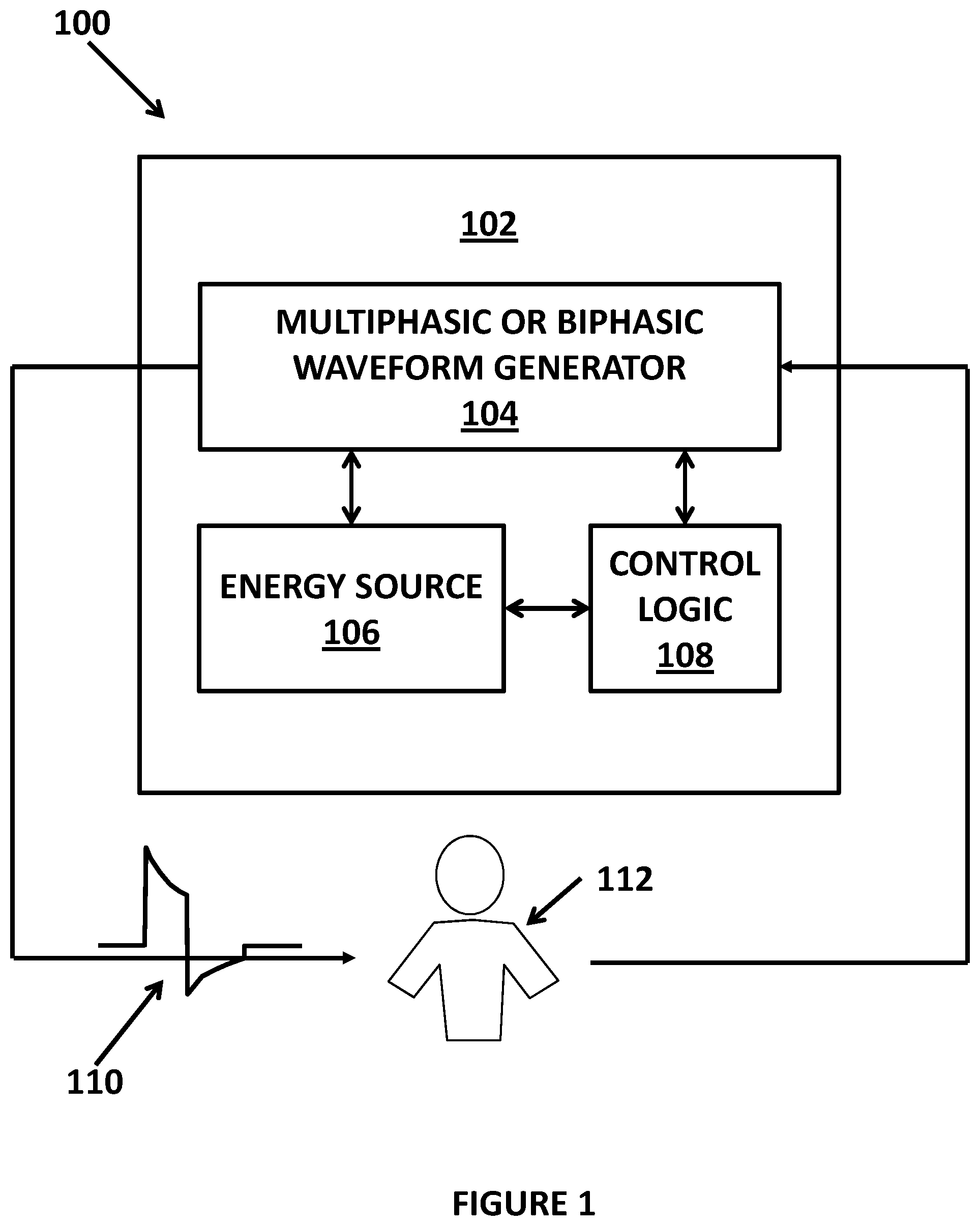
FIG. 1 illustrates a medical device that may generate and deliver a biphasic or multiphasic waveform;
FIG. 2 illustrates a standard biphasic pulse waveform where the second (negative) phase of the waveform is smaller in amplitude than that of the first (positive) phase of the waveform.
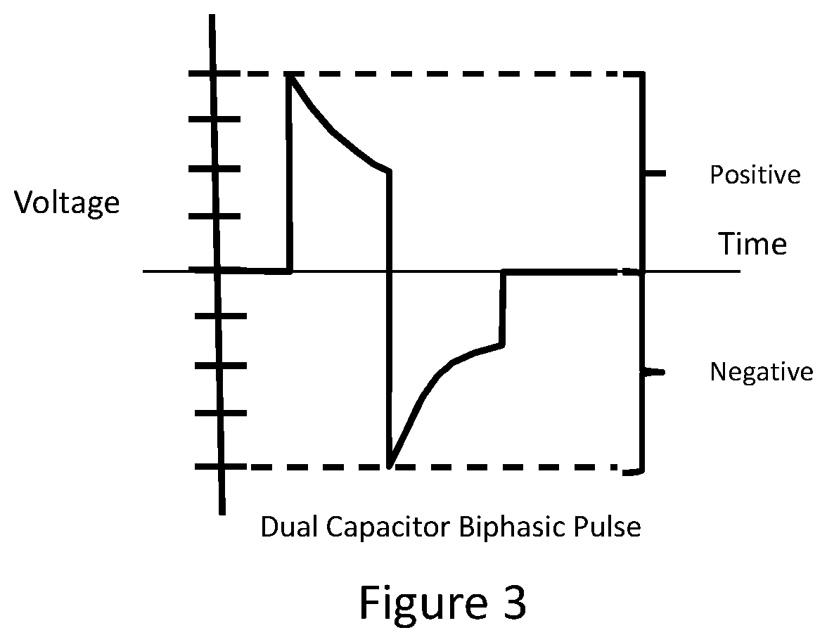
FIG. 3 illustrates the shape of a biphasic waveform where the first phase of the waveform is identical in amplitude to that of the second phase of the waveform.
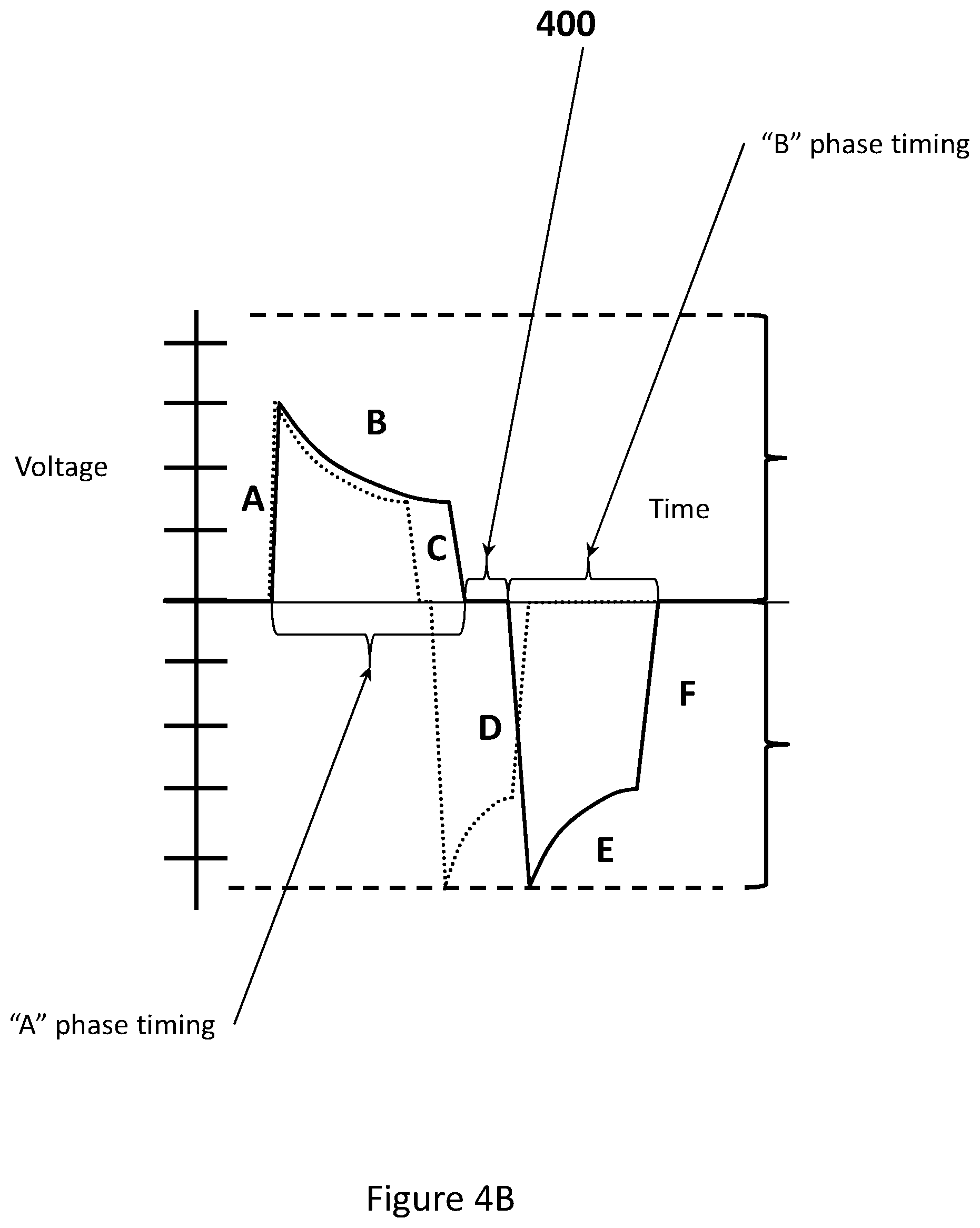
FIGS. 4A and 4B illustrate the shape of a biphasic pulse waveform where the first phase of the waveform is slightly smaller in amplitude than that of the second phase of the waveform.
FIG. 5 illustrates the shape of a biphasic pulse waveform where the first phase of the waveform is significantly smaller in amplitude than that of the second phase of the waveform.
FIG. 6 illustrates the shape of a biphasic pulse waveform where the first phase of the waveform is significantly smaller in amplitude than that of the second phase of the waveform, and where the first phase is a negative phase and the second phase is a positive phase.
FIG. 7 illustrates the shape of a multiphasic pulse waveform where the initial phase of the waveform is smaller in amplitude than the second phase of the waveform, regardless of the amplitude(s) of any phase(s) subsequent to the second phase of the waveform.
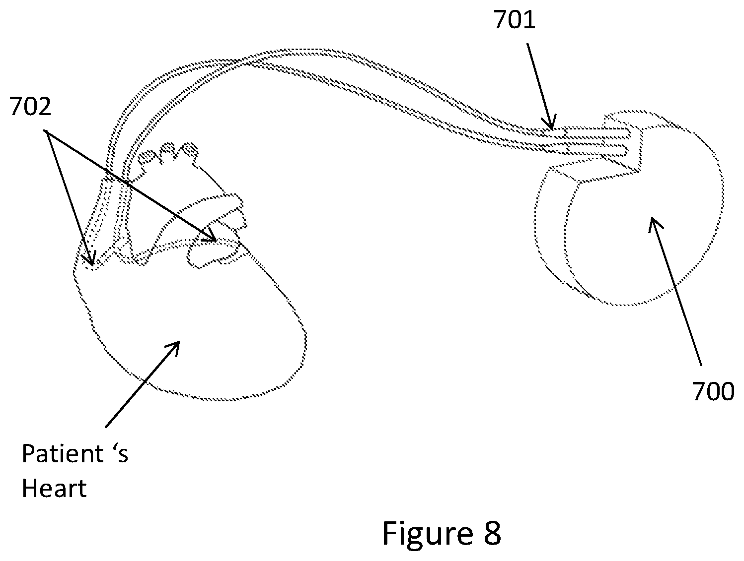
FIG. 8 diagrammatically illustrates an example of a conventional implantable cardioverter defibrillator
FIG. 9 diagrammatically illustrates an example of a conventional external defibrillator.
FIG. 10 illustrates a biphasic waveform where the first phase of the waveform is significantly smaller in amplitude than the amplitude of the second phase of the waveform and a range of phase tilt variables for each of the phases are shown diagrammatically.
FIG. 11 illustrates a biphasic waveform where each phase of the waveform (equal in size to each other) is switched on and off throughout the delivery process such that only a fraction of the maximum possible energy is actually delivered to the patient.
FIG. 12 illustrates a biphasic waveform where each phase of the waveform, where the first phase is smaller in amplitude than the second phase, is switched on and off throughout the delivery process such that only a fraction of the maximum possible energy is actually delivered to the patient.
DETAILED DESCRIPTION OF ONE OR MORE EMBODIMENTS
The novel biphasic or multiphasic pulse waveform is applicable for use with various medical devices including all defibrillator types: external (manual, semi-automated and fully automated), wearable and implanted. In addition to defibrillators, the medical device may also be cardioverters and external/internal pacers, as well as other types of electrical stimulation medical devices, such as: neuro-stimulators, musculo-skeletal stimulators, organ stimulators and nerve/peripheral nerve stimulators, whether the devices are external or implantable. The biphasic or multiphasic waveform pulse may be particularly useful for any type of defibrillator and examples of the biphasic or multiphasic waveform pulse will be described in the context of a defibrillator for illustration purposes.
The novel biphasic or multiphasic waveform pulse is a distinctly different family of waveforms compared to the standard biphasic waveforms (see FIG. 2) which has been used for the past several decades for defibrillators where the second phase's leading edge amplitude is the same as the first phase's trailing edge amplitude. The novel biphasic or multiphasic waveform pulse is also substantially different from the even higher energy dual capacitor biphasic waveform (see FIG. 3) that was explored in the 1980s. The biphasic or multiphasic waveform pulse is a novel family of biphasic, or multiphasic, waveforms where the initial phase of the waveform is smaller in amplitude than the amplitude of the second phase of the waveform (see FIGS. 4A-7 for example). The typical circuitry used to generate the typical biphasic pulse shown in FIG. 2 cannot be used to generate the biphasic or multiphasic waveform pulse described herein.
The novel biphasic or multiphasic waveform pulse allows for an efficacious pulse waveform to be delivered to the patient at a substantially lower level of total energy than ever before. In preclinical animal trials using the novel biphasic or multiphasic waveform pulse, successful defibrillation has been demonstrated using the novel biphasic or multiphasic waveform pulse, repeatedly, and at significantly lower levels of total delivered energy than the energy required by any current external defibrillators using either the original monophasic pulse or the now traditional biphasic pulse. For example, the novel biphasic or multiphasic waveform pulse may deliver 0.1 to 200 joules to a patient. Furthermore, the time for the waveform pulse delivery is between 1-20 ms and preferably 8-10 ms for the combined first and second phases of the waveform, although for triphasic and quadriphasic waveforms this is preferably in the 8-16 ms range for the entire waveform. For an embodiment in which the generated waveform is being used for nerve stimulation or neuro-stimulation, the waveform period may be on the order of microseconds or shorter.
The novel biphasic or multiphasic waveform pulse also significantly reduces both the total energy and the current levels that must be discharged into the patient, thus reducing the chance of either skin burns or other damage to the skin, tissue or organs of the patient. The novel biphasic or multiphasic waveform pulse also reduces the maximum amount of energy that a device is required to store and deliver, and it increases the maximum lifespan of any battery powered device due to a more frugal use of the energy stored within it. The novel biphasic or multiphasic waveform pulse also enables the production of smaller devices as a lower total amount of energy is needed to be stored and delivered to the patient.
The novel biphasic or multiphasic waveform pulse is effective across a wide range of values for multiple variables/characteristics of the novel biphasic or multiphasic waveform pulse. For example, FIGS. 4A and 4B show a biphasic waveform with a first phase (being positive polarity in this example) and a second phase (being negative polarity in this example) with the amplitude of the first phase being smaller than the second phase. As shown in FIG. 4B, a timing/duration of each phase (phase A and phase B) of the pulse waveform may be at least 1 millisecond for defibrillator medical devices and may be between 1-20 ms and an inter-phase period 400 between the first and second phases may be between 0 to 1500 microseconds. In addition, the first phase (that may be a positive polarity as shown in FIG. 4B or a negative polarity) may have a rise time of the leading edge A and an amplitude of the leading edge A, a time of decay slope B and a phase tilt of the decay slope B, a fall time of trailing edge C and an amplitude of the trailing edge C. In addition, the second phase (that may be a negative polarity as shown in FIG. 4B or a positive polarity, but is an opposite polarity of phase A) may have a rise time of leading edge D, an amplitude of the leading edge D, a time of decay slope E, a phase tilt of the decay slope E, a fall time of trailing edge F and an amplitude of the trailing edge F. The decay slope/tilt, for example, for each phase of the waveform may be between 0% and 95%. Each of the above characteristics of the pulse waveform may be adjusted and optimized depending on the exact therapeutic use to which the waveform is being put, as well as upon the nature and positioning of the device (external or implantable) and also upon the specifics of the patients themselves. Although a biphasic waveform is shown in FIG. 4B, a multiphasic waveform may have multiple phases (each phase with its own duration and amplitude) and multiple inter-phase periods. Each phase of the multiphasic waveform may have independent or the same adjustable rise time, slope time and fall time characteristics.
FIGS. 5 and 6 illustrate additional examples of a biphasic waveform. The example in FIG. 5 of the waveform has a first positive polarity phase and a second negative polarity phase. The example in FIG. 6 of the waveform has a first negative polarity phase and a second positive polarity phase. In the biphasic or multiphasic waveforms, the first phase has a polarity and then the second phase has an opposite polarity. FIG. 7 illustrates an example of a multiphasic waveform that has a plurality of positive polarity phases (3 in this example) and a plurality of negative polarity phases (3 in this example). As with the other examples, the amplitude of the first phase is smaller than the amplitudes of the subsequent positive phases and the negative phases.
In an additional embodiment, the novel biphasic or multiphasic waveform pulse may have different phase tilts for either or both phases as shown in FIG. 10. In addition, the novel biphasic or multiphasic waveform pulse may be generated and delivered to the patient in a lower energy manner, by only delivering portions of the pulse waveform to the patient. This can be done with the whole waveform (see FIG. 11 and FIG. 12) or else with individual phases of the waveform according to the energy conservation needs and the therapeutic needs. This can be accomplished via multiple means, including internal and external shunting of the current using high speed switching. In FIGS. 11-12, the novel biphasic or multiphasic waveform pulse may have a plurality of first phase pulses (with the same polarity) and then a plurality of second phase pulses that each have the same polarity, but opposite of the polarity of the first phase.
The novel biphasic or multiphasic waveform pulse may be generated in various manners. For example, as shown in FIG. 1, a medical device 102 may have a biphasic or multiphasic waveform generator 104 and an energy source 106 that may be coupled to a control logic unit 108. The control logic unit may control the biphasic or multiphasic waveform generator 104 and the energy source 106 to generate the biphasic or multiphasic waveform pulse. One skilled in the art would understand that various circuitry for the biphasic or multiphasic waveform generator 104, the energy source 106 and the control logic unit 108 may be used to generate the biphasic or multiphasic waveform pulse. An example of circuitry that may be used to generate the biphasic or multiphasic waveform pulse may be found in co-pending U.S. patent application Ser. No. 14/661,949, filed on Mar. 18, 2015, that is incorporated herein by reference.
While the foregoing has been with reference to a particular embodiment of the disclosure, it will be appreciated by those skilled in the art that changes in this embodiment may be made without departing from the principles and spirit of the disclosure, the scope of which is defined by the appended claims.
* * * * *
D00000
D00001
D00002
D00003
D00004
D00005
D00006
D00007
D00008
D00009
D00010
D00011
D00012

D00013

XML
uspto.report is an independent third-party trademark research tool that is not affiliated, endorsed, or sponsored by the United States Patent and Trademark Office (USPTO) or any other governmental organization. The information provided by uspto.report is based on publicly available data at the time of writing and is intended for informational purposes only.
While we strive to provide accurate and up-to-date information, we do not guarantee the accuracy, completeness, reliability, or suitability of the information displayed on this site. The use of this site is at your own risk. Any reliance you place on such information is therefore strictly at your own risk.
All official trademark data, including owner information, should be verified by visiting the official USPTO website at www.uspto.gov. This site is not intended to replace professional legal advice and should not be used as a substitute for consulting with a legal professional who is knowledgeable about trademark law.