Cardiac resynchronization using fusion promotion for timing management
Hahn , et al. December 22, 2
U.S. patent number 10,870,008 [Application Number 15/684,264] was granted by the patent office on 2020-12-22 for cardiac resynchronization using fusion promotion for timing management. This patent grant is currently assigned to CARDIAC PACEMAKERS, INC.. The grantee listed for this patent is CARDIAC PACEMAKERS, INC.. Invention is credited to Stephen J. Hahn, Scott J. Healy, John Morgan, Kenneth M. Stein, Yinghong Yu.


View All Diagrams
| United States Patent | 10,870,008 |
| Hahn , et al. | December 22, 2020 |
Cardiac resynchronization using fusion promotion for timing management
Abstract
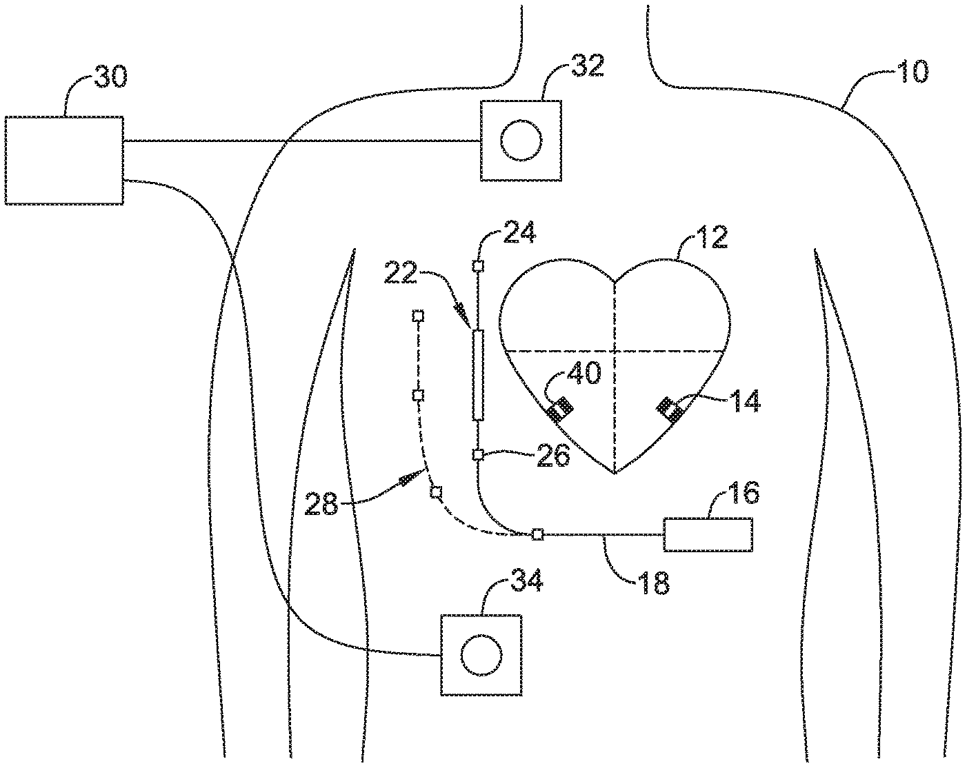
Methods, systems and devices for providing cardiac resynchronization therapy (CRT) to a patient using a leadless cardiac pacemaker and an extracardiac device. The extracardiac device is configured to analyze one or more QRS complexes of the patient's heart, determine whether fusion pacing is taking place, and, if not, to communicate with the leadless cardiac pacemaker to adjust intervals used in the CRT in order to generate desirable fusion of the pace and intrinsic signals. The extracardiac device may take the form of a subcutaneous implantable monitor, a subcutaneous implantable defibrillator, or other devices including wearable devices.
| Inventors: | Hahn; Stephen J. (Shoreview, MN), Stein; Kenneth M. (Minneapolis, MN), Yu; Yinghong (Shoreview, MN), Healy; Scott J. (Maple Grove, MN), Morgan; John (Houghton, GB) | ||||||||||
|---|---|---|---|---|---|---|---|---|---|---|---|
| Applicant: |
|
||||||||||
| Assignee: | CARDIAC PACEMAKERS, INC. (St.
Paul, MN) |
||||||||||
| Family ID: | 1000005255722 | ||||||||||
| Appl. No.: | 15/684,264 | ||||||||||
| Filed: | August 23, 2017 |
Prior Publication Data
| Document Identifier | Publication Date | |
|---|---|---|
| US 20180056079 A1 | Mar 1, 2018 | |
Related U.S. Patent Documents
| Application Number | Filing Date | Patent Number | Issue Date | ||
|---|---|---|---|---|---|
| 62378866 | Aug 24, 2016 | ||||
| Current U.S. Class: | 1/1 |
| Current CPC Class: | A61N 1/3756 (20130101); A61N 1/3962 (20130101); A61B 5/04525 (20130101); A61N 1/378 (20130101); A61N 1/37252 (20130101); A61N 1/36592 (20130101); A61N 1/3918 (20130101); A61N 1/3627 (20130101); A61B 5/0456 (20130101); A61N 1/39622 (20170801); A61N 1/3682 (20130101); A61N 1/37288 (20130101); A61N 1/36843 (20170801); A61N 1/37512 (20170801) |
| Current International Class: | A61N 1/372 (20060101); A61B 5/0456 (20060101); A61N 1/365 (20060101); A61N 1/39 (20060101); A61N 1/368 (20060101); A61N 1/378 (20060101); A61N 1/375 (20060101); A61N 1/362 (20060101); A61B 5/0452 (20060101) |
References Cited [Referenced By]
U.S. Patent Documents
| 3835864 | September 1974 | Rasor et al. |
| 3943936 | March 1976 | Rasor et al. |
| 4142530 | March 1979 | Wittkampf |
| 4151513 | April 1979 | Menken et al. |
| 4157720 | June 1979 | Greatbatch |
| RE30366 | August 1980 | Rasor et al. |
| 4243045 | January 1981 | Maas |
| 4250884 | February 1981 | Hartlaub et al. |
| 4256115 | March 1981 | Bilitch |
| 4263919 | April 1981 | Levin |
| 4310000 | January 1982 | Lindemans |
| 4312354 | January 1982 | Walters |
| 4323081 | April 1982 | Wiebusch |
| 4357946 | November 1982 | Dutcher et al. |
| 4365639 | December 1982 | Goldreyer |
| 4440173 | April 1984 | Hudziak et al. |
| 4476868 | October 1984 | Thompson |
| 4522208 | June 1985 | Buffet |
| 4537200 | August 1985 | Widrow |
| 4556063 | December 1985 | Thompson et al. |
| 4562841 | January 1986 | Brockway et al. |
| 4593702 | June 1986 | Kepski et al. |
| 4593955 | June 1986 | Leiber |
| 4630611 | December 1986 | King |
| 4635639 | January 1987 | Hakala et al. |
| 4674508 | June 1987 | DeCote |
| 4712554 | December 1987 | Garson |
| 4729376 | March 1988 | DeCote |
| 4754753 | July 1988 | King |
| 4759366 | July 1988 | Callaghan |
| 4776338 | October 1988 | Lekholm et al. |
| 4787389 | November 1988 | Tarjan |
| 4793353 | December 1988 | Borkan |
| 4819662 | April 1989 | Heil et al. |
| 4858610 | August 1989 | Callaghan et al. |
| 4886064 | December 1989 | Strandberg |
| 4887609 | December 1989 | Cole, Jr. |
| 4928688 | May 1990 | Mower |
| 4967746 | November 1990 | Vandegriff |
| 4987897 | January 1991 | Funke |
| 4989602 | February 1991 | Sholder et al. |
| 5012806 | May 1991 | De Bellis |
| 5036849 | August 1991 | Hauck et al. |
| 5040534 | August 1991 | Mann et al. |
| 5058581 | October 1991 | Silvian |
| 5078134 | January 1992 | Heilman et al. |
| 5109845 | May 1992 | Yuuchi et al. |
| 5113859 | May 1992 | Funke |
| 5113869 | May 1992 | Nappholz et al. |
| 5117824 | June 1992 | Keimel et al. |
| 5127401 | July 1992 | Grevious et al. |
| 5133353 | July 1992 | Hauser |
| 5144950 | September 1992 | Stoop et al. |
| 5170784 | December 1992 | Ramon et al. |
| 5179945 | January 1993 | Van Hofwegen et al. |
| 5193539 | March 1993 | Schulman et al. |
| 5193540 | March 1993 | Schulman et al. |
| 5241961 | September 1993 | Henry |
| 5243977 | September 1993 | Trabucco et al. |
| 5259387 | November 1993 | dePinto |
| 5269326 | December 1993 | Verrier |
| 5284136 | February 1994 | Hauck et al. |
| 5300107 | April 1994 | Stokes et al. |
| 5301677 | April 1994 | Hsung |
| 5305760 | April 1994 | McKown et al. |
| 5312439 | May 1994 | Loeb |
| 5313953 | May 1994 | Yomtov et al. |
| 5314459 | May 1994 | Swanson et al. |
| 5318597 | June 1994 | Hauck et al. |
| 5324316 | June 1994 | Schulman et al. |
| 5331966 | July 1994 | Bennett et al. |
| 5334222 | August 1994 | Salo et al. |
| 5342408 | August 1994 | deCoriolis et al. |
| 5370667 | December 1994 | Alt |
| 5372606 | December 1994 | Lang et al. |
| 5376106 | December 1994 | Stahmann et al. |
| 5383915 | January 1995 | Adams |
| 5388578 | February 1995 | Yomtov et al. |
| 5404877 | April 1995 | Nolan et al. |
| 5405367 | April 1995 | Schulman et al. |
| 5411031 | May 1995 | Yomtov |
| 5411525 | May 1995 | Swanson et al. |
| 5411535 | May 1995 | Fujii et al. |
| 5456691 | October 1995 | Snell |
| 5458622 | October 1995 | Alt |
| 5466246 | November 1995 | Silvian |
| 5468254 | November 1995 | Hahn et al. |
| 5472453 | December 1995 | Alt |
| 5522866 | June 1996 | Fernald |
| 5540727 | July 1996 | Tockman et al. |
| 5545186 | August 1996 | Olson et al. |
| 5545202 | August 1996 | Dahl et al. |
| 5571146 | November 1996 | Jones et al. |
| 5591214 | January 1997 | Lu |
| 5620466 | April 1997 | Haefner et al. |
| 5634938 | June 1997 | Swanson et al. |
| 5649968 | July 1997 | Alt et al. |
| 5662688 | September 1997 | Haefner et al. |
| 5674259 | October 1997 | Gray |
| 5683426 | November 1997 | Greenhut et al. |
| 5683432 | November 1997 | Goedeke et al. |
| 5702427 | December 1997 | Ecker et al. |
| 5706823 | January 1998 | Wodlinger |
| 5709215 | January 1998 | Perttu et al. |
| 5720770 | February 1998 | Nappholz et al. |
| 5728154 | March 1998 | Crossett et al. |
| 5741314 | April 1998 | Daly et al. |
| 5741315 | April 1998 | Lee et al. |
| 5752976 | May 1998 | Duffin et al. |
| 5752977 | May 1998 | Grevious et al. |
| 5755736 | May 1998 | Gillberg et al. |
| 5759199 | June 1998 | Snell et al. |
| 5774501 | June 1998 | Halpern et al. |
| 5792195 | August 1998 | Carlson et al. |
| 5792202 | August 1998 | Rueter |
| 5792203 | August 1998 | Schroeppel |
| 5792205 | August 1998 | Alt et al. |
| 5792208 | August 1998 | Gray |
| 5814089 | September 1998 | Stokes et al. |
| 5827216 | October 1998 | Igo et al. |
| 5836985 | November 1998 | Goyal et al. |
| 5836987 | November 1998 | Baumann et al. |
| 5842977 | December 1998 | Lesho et al. |
| 5855593 | January 1999 | Olson et al. |
| 5873894 | February 1999 | Vandegriff et al. |
| 5891184 | April 1999 | Lee et al. |
| 5897586 | April 1999 | Molina |
| 5899876 | May 1999 | Flower |
| 5899928 | May 1999 | Sholder et al. |
| 5919214 | July 1999 | Ciciarelli et al. |
| 5935078 | August 1999 | Feierbach |
| 5941906 | August 1999 | Barreras, Sr. et al. |
| 5944744 | August 1999 | Paul et al. |
| 5954757 | September 1999 | Gray |
| 5978713 | November 1999 | Prutchi et al. |
| 5991660 | November 1999 | Goyal |
| 5991661 | November 1999 | Park et al. |
| 5999848 | December 1999 | Gord et al. |
| 5999857 | December 1999 | Weijand et al. |
| 6016445 | January 2000 | Baura |
| 6026320 | February 2000 | Carlson et al. |
| 6029085 | February 2000 | Olson et al. |
| 6041250 | March 2000 | dePinto |
| 6044298 | March 2000 | Salo et al. |
| 6044300 | March 2000 | Gray |
| 6055454 | April 2000 | Heemels |
| 6073050 | June 2000 | Griffith |
| 6076016 | June 2000 | Feierbach |
| 6077236 | June 2000 | Cunningham |
| 6080187 | June 2000 | Alt et al. |
| 6083248 | July 2000 | Thompson |
| 6106551 | August 2000 | Crossett et al. |
| 6115636 | September 2000 | Ryan |
| 6128526 | October 2000 | Stadler et al. |
| 6141581 | October 2000 | Olson et al. |
| 6141588 | October 2000 | Cox et al. |
| 6141592 | October 2000 | Pauly |
| 6144879 | November 2000 | Gray |
| 6162195 | December 2000 | Igo et al. |
| 6164284 | December 2000 | Schulman et al. |
| 6167310 | December 2000 | Grevious |
| 6201993 | March 2001 | Kruse et al. |
| 6208894 | March 2001 | Schulman et al. |
| 6211799 | April 2001 | Post et al. |
| 6221011 | April 2001 | Bardy |
| 6240316 | May 2001 | Richmond et al. |
| 6240317 | May 2001 | Villaseca et al. |
| 6256534 | July 2001 | Dahl |
| 6259947 | July 2001 | Olson et al. |
| 6266558 | July 2001 | Gozani et al. |
| 6266567 | July 2001 | Ishikawa et al. |
| 6270457 | August 2001 | Bardy |
| 6272377 | August 2001 | Sweeney et al. |
| 6273856 | August 2001 | Sun et al. |
| 6277072 | August 2001 | Bardy |
| 6280380 | August 2001 | Bardy |
| 6285907 | September 2001 | Kramer et al. |
| 6292698 | September 2001 | Duffin et al. |
| 6295473 | September 2001 | Rosar |
| 6297943 | October 2001 | Carson |
| 6298271 | October 2001 | Weijand |
| 6307751 | October 2001 | Bodony et al. |
| 6312378 | November 2001 | Bardy |
| 6315721 | November 2001 | Schulman et al. |
| 6336903 | January 2002 | Bardy |
| 6345202 | February 2002 | Richmond et al. |
| 6351667 | February 2002 | Godie |
| 6351669 | February 2002 | Hartley et al. |
| 6353759 | March 2002 | Hartley et al. |
| 6358203 | March 2002 | Bardy |
| 6361780 | March 2002 | Ley et al. |
| 6368284 | April 2002 | Bardy |
| 6371922 | April 2002 | Baumann et al. |
| 6398728 | June 2002 | Bardy |
| 6400982 | June 2002 | Sweeney et al. |
| 6400990 | June 2002 | Silvian |
| 6408208 | June 2002 | Sun |
| 6409674 | June 2002 | Brockway et al. |
| 6411848 | June 2002 | Kramer et al. |
| 6424865 | July 2002 | Ding |
| 6434429 | August 2002 | Kraus et al. |
| 6438410 | August 2002 | Hsu et al. |
| 6438417 | August 2002 | Rockwell et al. |
| 6438421 | August 2002 | Stahmann et al. |
| 6440066 | August 2002 | Bardy |
| 6441747 | August 2002 | Khair et al. |
| 6442426 | August 2002 | Kroll |
| 6442432 | August 2002 | Lee |
| 6443891 | September 2002 | Grevious |
| 6445953 | September 2002 | Bulkes et al. |
| 6453200 | September 2002 | Koslar |
| 6459929 | October 2002 | Hopper et al. |
| 6470215 | October 2002 | Kraus et al. |
| 6471645 | October 2002 | Warkentin et al. |
| 6480745 | November 2002 | Nelson et al. |
| 6487443 | November 2002 | Olson et al. |
| 6490487 | December 2002 | Kraus et al. |
| 6498951 | December 2002 | Larson et al. |
| 6505077 | January 2003 | Kast et al. |
| 6507755 | January 2003 | Gozani et al. |
| 6507759 | January 2003 | Prutchi et al. |
| 6512940 | January 2003 | Brabec et al. |
| 6522915 | February 2003 | Ceballos et al. |
| 6526311 | February 2003 | Begemann |
| 6539253 | March 2003 | Thompson et al. |
| 6542775 | April 2003 | Ding et al. |
| 6553258 | April 2003 | Stahmann et al. |
| 6561975 | May 2003 | Pool et al. |
| 6564807 | May 2003 | Schulman et al. |
| 6574506 | June 2003 | Kramer et al. |
| 6584351 | June 2003 | Ekwall |
| 6584352 | June 2003 | Combs et al. |
| 6597948 | July 2003 | Rockwell et al. |
| 6597951 | July 2003 | Kramer et al. |
| 6622046 | September 2003 | Fraley et al. |
| 6628985 | September 2003 | Sweeney et al. |
| 6647292 | November 2003 | Bardy et al. |
| 6666844 | December 2003 | Igo et al. |
| 6689117 | February 2004 | Sweeney et al. |
| 6690959 | February 2004 | Thompson |
| 6694189 | February 2004 | Begemann |
| 6704602 | March 2004 | Berg et al. |
| 6718212 | April 2004 | Parry et al. |
| 6721597 | April 2004 | Bardy et al. |
| 6738670 | May 2004 | Almendinger et al. |
| 6746797 | June 2004 | Benson et al. |
| 6749566 | June 2004 | Russ |
| 6758810 | July 2004 | Lebel et al. |
| 6763269 | July 2004 | Cox |
| 6778860 | August 2004 | Ostroff et al. |
| 6788971 | September 2004 | Sloman et al. |
| 6788974 | September 2004 | Bardy et al. |
| 6804558 | October 2004 | Haller et al. |
| 6807442 | October 2004 | Myklebust et al. |
| 6847844 | January 2005 | Sun et al. |
| 6871095 | March 2005 | Stahmann et al. |
| 6878112 | April 2005 | Linberg et al. |
| 6885889 | April 2005 | Chinchoy |
| 6892094 | May 2005 | Ousdigian et al. |
| 6897788 | May 2005 | Khair et al. |
| 6904315 | June 2005 | Panken et al. |
| 6922592 | July 2005 | Thompson et al. |
| 6931282 | August 2005 | Esler |
| 6934585 | August 2005 | Schloss et al. |
| 6957107 | October 2005 | Rogers et al. |
| 6978176 | December 2005 | Lattouf |
| 6985773 | January 2006 | Von Arx et al. |
| 6990375 | January 2006 | Kloss et al. |
| 7001366 | February 2006 | Ballard |
| 7003350 | February 2006 | Denker et al. |
| 7006864 | February 2006 | Echt et al. |
| 7013178 | March 2006 | Reinke et al. |
| 7027871 | April 2006 | Burnes et al. |
| 7050849 | May 2006 | Echt et al. |
| 7060031 | June 2006 | Webb et al. |
| 7063693 | June 2006 | Guenst |
| 7082336 | July 2006 | Ransbury et al. |
| 7085606 | August 2006 | Flach et al. |
| 7092758 | August 2006 | Sun et al. |
| 7110824 | September 2006 | Amundson et al. |
| 7120504 | October 2006 | Osypka |
| 7130681 | October 2006 | Gebhardt et al. |
| 7139613 | November 2006 | Reinke et al. |
| 7142912 | November 2006 | Wagner et al. |
| 7146225 | December 2006 | Guenst et al. |
| 7146226 | December 2006 | Lau et al. |
| 7149575 | December 2006 | Ostroff et al. |
| 7149581 | December 2006 | Goedeke |
| 7149588 | December 2006 | Lau et al. |
| 7158839 | January 2007 | Lau |
| 7162307 | January 2007 | Patrias |
| 7164952 | January 2007 | Lau et al. |
| 7177700 | February 2007 | Cox |
| 7181505 | February 2007 | Haller et al. |
| 7184830 | February 2007 | Echt et al. |
| 7186214 | March 2007 | Ness |
| 7189204 | March 2007 | Ni et al. |
| 7191015 | March 2007 | Lamson et al. |
| 7200437 | April 2007 | Nabutovsky et al. |
| 7200439 | April 2007 | Zdeblick et al. |
| 7206423 | April 2007 | Feng et al. |
| 7209785 | April 2007 | Kim et al. |
| 7209790 | April 2007 | Thompson et al. |
| 7211884 | May 2007 | Davis et al. |
| 7212871 | May 2007 | Morgan |
| 7226440 | June 2007 | Gelfand et al. |
| 7228183 | June 2007 | Sun et al. |
| 7236821 | June 2007 | Cates et al. |
| 7236829 | June 2007 | Farazi et al. |
| 7254448 | August 2007 | Almendinger et al. |
| 7260436 | August 2007 | Kilgore et al. |
| 7270669 | September 2007 | Sra |
| 7272448 | September 2007 | Morgan et al. |
| 7277755 | October 2007 | Falkenberg et al. |
| 7280872 | October 2007 | Mosesov et al. |
| 7288096 | October 2007 | Chin |
| 7289847 | October 2007 | Gill et al. |
| 7289852 | October 2007 | Helfinstine et al. |
| 7289853 | October 2007 | Campbell et al. |
| 7289855 | October 2007 | Nghiem et al. |
| 7302294 | November 2007 | Kamath et al. |
| 7305266 | December 2007 | Kroll |
| 7310556 | December 2007 | Bulkes |
| 7319905 | January 2008 | Morgan et al. |
| 7333853 | February 2008 | Mazar et al. |
| 7336994 | February 2008 | Hettrick et al. |
| 7347819 | March 2008 | Lebel et al. |
| 7366572 | April 2008 | Heruth et al. |
| 7373207 | May 2008 | Lattouf |
| 7376458 | May 2008 | Palreddy et al. |
| 7384403 | June 2008 | Sherman |
| 7386342 | June 2008 | Falkenberg et al. |
| 7392090 | June 2008 | Sweeney et al. |
| 7406105 | July 2008 | DelMain et al. |
| 7406349 | July 2008 | Seeberger et al. |
| 7410497 | August 2008 | Hastings et al. |
| 7425200 | September 2008 | Brockway et al. |
| 7433739 | October 2008 | Salys et al. |
| 7477935 | January 2009 | Palreddy et al. |
| 7496409 | February 2009 | Greenhut et al. |
| 7496410 | February 2009 | Heil |
| 7502652 | March 2009 | Gaunt et al. |
| 7512448 | March 2009 | Malick et al. |
| 7515969 | April 2009 | Tockman et al. |
| 7526342 | April 2009 | Chin et al. |
| 7529589 | May 2009 | Williams et al. |
| 7532933 | May 2009 | Hastings et al. |
| 7536222 | May 2009 | Bardy et al. |
| 7536224 | May 2009 | Ritscher et al. |
| 7539541 | May 2009 | Quiles et al. |
| 7544197 | June 2009 | Kelsch et al. |
| 7558631 | July 2009 | Cowan et al. |
| 7565195 | July 2009 | Kroll et al. |
| 7584002 | September 2009 | Burnes et al. |
| 7590455 | September 2009 | Heruth et al. |
| 7606621 | October 2009 | Brisken et al. |
| 7610088 | October 2009 | Chinchoy |
| 7610092 | October 2009 | Cowan et al. |
| 7610099 | October 2009 | Almendinger et al. |
| 7610104 | October 2009 | Kaplan et al. |
| 7616991 | November 2009 | Mann et al. |
| 7617001 | November 2009 | Penner et al. |
| 7617007 | November 2009 | Williams et al. |
| 7630767 | December 2009 | Poore et al. |
| 7634313 | December 2009 | Kroll et al. |
| 7637867 | December 2009 | Zdeblick |
| 7640060 | December 2009 | Zdeblick |
| 7647109 | January 2010 | Hastings et al. |
| 7650186 | January 2010 | Hastings et al. |
| 7657311 | February 2010 | Bardy et al. |
| 7668596 | February 2010 | Von Arx et al. |
| 7682316 | March 2010 | Anderson et al. |
| 7691047 | April 2010 | Ferrari |
| 7702392 | April 2010 | Echt et al. |
| 7713194 | May 2010 | Zdeblick |
| 7713195 | May 2010 | Zdeblick |
| 7729783 | June 2010 | Michels et al. |
| 7734333 | June 2010 | Ghanem et al. |
| 7734343 | June 2010 | Ransbury et al. |
| 7738958 | June 2010 | Zdeblick et al. |
| 7738964 | June 2010 | Von Arx et al. |
| 7742812 | June 2010 | Ghanem et al. |
| 7742816 | June 2010 | Masoud et al. |
| 7742822 | June 2010 | Masoud et al. |
| 7743151 | June 2010 | Vallapureddy et al. |
| 7747335 | June 2010 | Williams |
| 7751881 | July 2010 | Cowan et al. |
| 7758521 | July 2010 | Morris et al. |
| 7761150 | July 2010 | Ghanem et al. |
| 7761164 | July 2010 | Verhoef et al. |
| 7765001 | July 2010 | Echt et al. |
| 7769452 | August 2010 | Ghanem et al. |
| 7783340 | August 2010 | Sanghera et al. |
| 7783362 | August 2010 | Whitehurst et al. |
| 7792588 | September 2010 | Harding |
| 7797059 | September 2010 | Bornzin et al. |
| 7801596 | September 2010 | Fischell et al. |
| 7809438 | October 2010 | Echt et al. |
| 7809441 | October 2010 | Kane et al. |
| 7840281 | November 2010 | Kveen et al. |
| 7844331 | November 2010 | Li et al. |
| 7844348 | November 2010 | Swoyer et al. |
| 7846088 | December 2010 | Ness |
| 7848815 | December 2010 | Brisken et al. |
| 7848823 | December 2010 | Drasler et al. |
| 7860455 | December 2010 | Fukumoto et al. |
| 7871433 | January 2011 | Lattouf |
| 7877136 | January 2011 | Moffitt et al. |
| 7877142 | January 2011 | Moaddeb et al. |
| 7881786 | February 2011 | Jackson |
| 7881798 | February 2011 | Miesel et al. |
| 7881810 | February 2011 | Chitre et al. |
| 7890173 | February 2011 | Brisken et al. |
| 7890181 | February 2011 | Denzene et al. |
| 7890192 | February 2011 | Kelsch et al. |
| 7894885 | February 2011 | Bartal et al. |
| 7894894 | February 2011 | Stadler et al. |
| 7894907 | February 2011 | Cowan et al. |
| 7894910 | February 2011 | Cowan et al. |
| 7894915 | February 2011 | Chitre et al. |
| 7899537 | March 2011 | Kroll et al. |
| 7899541 | March 2011 | Cowan et al. |
| 7899542 | March 2011 | Cowan et al. |
| 7899554 | March 2011 | Williams et al. |
| 7901360 | March 2011 | Yang et al. |
| 7904170 | March 2011 | Harding |
| 7907993 | March 2011 | Ghanem et al. |
| 7920928 | April 2011 | Yang et al. |
| 7925343 | April 2011 | Min et al. |
| 7930022 | April 2011 | Zhang et al. |
| 7930040 | April 2011 | Kelsch et al. |
| 7937135 | May 2011 | Ghanem et al. |
| 7937148 | May 2011 | Jacobson |
| 7937161 | May 2011 | Hastings et al. |
| 7941214 | May 2011 | Kleckner et al. |
| 7945333 | May 2011 | Jacobson |
| 7946997 | May 2011 | Hubinette |
| 7949404 | May 2011 | Hill |
| 7949405 | May 2011 | Feher |
| 7953486 | May 2011 | Daum et al. |
| 7953493 | May 2011 | Fowler et al. |
| 7962202 | June 2011 | Bhunia |
| 7974702 | July 2011 | Fain et al. |
| 7979136 | July 2011 | Young et al. |
| 7983753 | July 2011 | Severin |
| 7991467 | August 2011 | Markowitz et al. |
| 7991471 | August 2011 | Ghanem et al. |
| 7996087 | August 2011 | Cowan et al. |
| 8000791 | August 2011 | Sunagawa et al. |
| 8000807 | August 2011 | Morris et al. |
| 8001975 | August 2011 | DiSilvestro et al. |
| 8002700 | August 2011 | Ferek-Petric et al. |
| 8010209 | August 2011 | Jacobson |
| 8019419 | September 2011 | Panescu et al. |
| 8019434 | September 2011 | Quiles et al. |
| 8027727 | September 2011 | Freeberg |
| 8027729 | September 2011 | Sunagawa et al. |
| 8032219 | October 2011 | Neumann et al. |
| 8036743 | October 2011 | Savage et al. |
| 8046080 | October 2011 | Von Arx et al. |
| 8050297 | November 2011 | DelMain et al. |
| 8050759 | November 2011 | Stegemann et al. |
| 8050774 | November 2011 | Kveen et al. |
| 8055345 | November 2011 | Li et al. |
| 8055350 | November 2011 | Roberts |
| 8060212 | November 2011 | Rios et al. |
| 8065018 | November 2011 | Haubrich et al. |
| 8073542 | December 2011 | Doerr |
| 8078278 | December 2011 | Penner |
| 8078283 | December 2011 | Cowan et al. |
| 8079959 | December 2011 | Sanghera et al. |
| 8095123 | January 2012 | Gray |
| 8102789 | January 2012 | Rosar et al. |
| 8103359 | January 2012 | Reddy |
| 8103361 | January 2012 | Moser |
| 8112148 | February 2012 | Giftakis et al. |
| 8114021 | February 2012 | Robertson et al. |
| 8116867 | February 2012 | Ostroff |
| 8121680 | February 2012 | Falkenberg et al. |
| 8123684 | February 2012 | Zdeblick |
| 8126545 | February 2012 | Flach et al. |
| 8131334 | March 2012 | Lu et al. |
| 8140161 | March 2012 | Willerton et al. |
| 8150521 | April 2012 | Crowley et al. |
| 8157813 | April 2012 | Ko et al. |
| 8160672 | April 2012 | Kim et al. |
| 8160702 | April 2012 | Mann et al. |
| 8160704 | April 2012 | Freeberg |
| 8165694 | April 2012 | Carbanaru et al. |
| 8175715 | May 2012 | Cox |
| 8180451 | May 2012 | Hickman et al. |
| 8185213 | May 2012 | Kveen et al. |
| 8187161 | May 2012 | Li et al. |
| 8195293 | June 2012 | Limousin et al. |
| 8195308 | June 2012 | Frank et al. |
| 8200341 | June 2012 | Sanghera et al. |
| 8204595 | June 2012 | Pianca et al. |
| 8204605 | June 2012 | Hastings et al. |
| 8209014 | June 2012 | Doerr |
| 8214043 | July 2012 | Matos |
| 8224244 | July 2012 | Kim et al. |
| 8229556 | July 2012 | Li |
| 8233985 | July 2012 | Bulkes et al. |
| 8265748 | September 2012 | Liu et al. |
| 8265757 | September 2012 | Mass et al. |
| 8262578 | October 2012 | Bharmi et al. |
| 8280521 | October 2012 | Haubrich et al. |
| 8285387 | October 2012 | Utsi et al. |
| 8290598 | October 2012 | Boon et al. |
| 8290600 | October 2012 | Hastings et al. |
| 8295939 | October 2012 | Jacobson |
| 8301254 | October 2012 | Mosesov et al. |
| 8315701 | November 2012 | Cowan et al. |
| 8315708 | November 2012 | Berthelsdorf et al. |
| 8321021 | November 2012 | Kisker et al. |
| 8321036 | November 2012 | Brockway et al. |
| 8332034 | December 2012 | Patangay et al. |
| 8332036 | December 2012 | Hastings et al. |
| 8335563 | December 2012 | Stessman |
| 8335568 | December 2012 | Heruth et al. |
| 8340750 | December 2012 | Prakash et al. |
| 8340780 | December 2012 | Hastings et al. |
| 8352025 | January 2013 | Jacobson |
| 8352028 | January 2013 | Wenger |
| 8352038 | January 2013 | Mao et al. |
| 8359098 | January 2013 | Lund et al. |
| 8364261 | January 2013 | Stubbs et al. |
| 8364276 | January 2013 | Willis |
| 8369959 | February 2013 | Meskens |
| 8369962 | February 2013 | Abrahamson |
| 8380320 | February 2013 | Spital |
| 8386051 | February 2013 | Rys |
| 8391981 | March 2013 | Mosesov |
| 8391990 | March 2013 | Smith et al. |
| 8406874 | March 2013 | Liu et al. |
| 8406879 | March 2013 | Shuros et al. |
| 8406886 | March 2013 | Gaunt et al. |
| 8412352 | April 2013 | Griswold et al. |
| 8417340 | April 2013 | Goossen |
| 8417341 | April 2013 | Freeberg |
| 8423149 | April 2013 | Hennig |
| 8428722 | April 2013 | Verhoef et al. |
| 8433402 | April 2013 | Ruben et al. |
| 8433409 | April 2013 | Johnson et al. |
| 8433420 | April 2013 | Bange et al. |
| 8447412 | May 2013 | Dal Molin et al. |
| 8452413 | May 2013 | Young et al. |
| 8457740 | June 2013 | Osche |
| 8457742 | June 2013 | Jacobson |
| 8457744 | June 2013 | Janzig et al. |
| 8457761 | June 2013 | Wariar |
| 8478399 | July 2013 | Degroot et al. |
| 8478407 | July 2013 | Demmer et al. |
| 8478408 | July 2013 | Hastings et al. |
| 8478431 | July 2013 | Griswold et al. |
| 8483843 | July 2013 | Sanghera et al. |
| 8494632 | July 2013 | Sun et al. |
| 8504156 | August 2013 | Bonner et al. |
| 8509910 | August 2013 | Sowder et al. |
| 8515559 | August 2013 | Roberts et al. |
| 8525340 | September 2013 | Eckhardt et al. |
| 8527068 | September 2013 | Ostroff |
| 8532790 | September 2013 | Griswold |
| 8538526 | September 2013 | Stahmann et al. |
| 8541131 | September 2013 | Lund et al. |
| 8543205 | September 2013 | Ostroff |
| 8547248 | October 2013 | Zdeblick et al. |
| 8548605 | October 2013 | Ollivier |
| 8554333 | October 2013 | Wu et al. |
| 8565878 | October 2013 | Allavatam et al. |
| 8565882 | October 2013 | Matos |
| 8565897 | October 2013 | Regnier et al. |
| 8571678 | October 2013 | Wang |
| 8577327 | November 2013 | Makdissi et al. |
| 8588926 | November 2013 | Moore et al. |
| 8612002 | December 2013 | Faltys et al. |
| 8615310 | December 2013 | Khairkhahan et al. |
| 8626280 | January 2014 | Allavatam et al. |
| 8626294 | January 2014 | Sheldon et al. |
| 8626310 | January 2014 | Barror et al. |
| 8634908 | January 2014 | Cowan |
| 8634912 | January 2014 | Bornzin et al. |
| 8634919 | January 2014 | Hou et al. |
| 8639335 | January 2014 | Peichel et al. |
| 8644934 | February 2014 | Hastings et al. |
| 8649859 | February 2014 | Smith et al. |
| 8670842 | March 2014 | Bornzin et al. |
| 8676319 | March 2014 | Knoll |
| 8676335 | March 2014 | Katoozi et al. |
| 8700173 | April 2014 | Edlund |
| 8700181 | April 2014 | Bornzin et al. |
| 8705599 | April 2014 | dal Molin et al. |
| 8718766 | May 2014 | Wahlberg |
| 8718773 | May 2014 | Willis et al. |
| 8725260 | May 2014 | Shuros et al. |
| 8738133 | May 2014 | Shuros et al. |
| 8738147 | May 2014 | Hastings et al. |
| 8744555 | June 2014 | Allavatam et al. |
| 8744572 | June 2014 | Greenhut et al. |
| 8747314 | June 2014 | Stahmann et al. |
| 8755884 | June 2014 | Demmer et al. |
| 8758365 | June 2014 | Bonner et al. |
| 8768483 | July 2014 | Schmitt et al. |
| 8774572 | July 2014 | Hamamoto |
| 8781605 | July 2014 | Bornzin et al. |
| 8788035 | July 2014 | Jacobson |
| 8788053 | July 2014 | Jacobson |
| 8798740 | August 2014 | Samade et al. |
| 8798745 | August 2014 | Jacobson |
| 8798762 | August 2014 | Fain et al. |
| 8798770 | August 2014 | Reddy |
| 8805505 | August 2014 | Roberts |
| 8805528 | August 2014 | Corndort |
| 8812109 | August 2014 | Blomqvist et al. |
| 8818504 | August 2014 | Bodner et al. |
| 8827913 | September 2014 | Havel et al. |
| 8831747 | September 2014 | Min et al. |
| 8855789 | October 2014 | Jacobson |
| 8868186 | October 2014 | Kroll |
| 8886325 | November 2014 | Boling et al. |
| 8886339 | November 2014 | Faltys et al. |
| 8903473 | December 2014 | Rogers et al. |
| 8903500 | December 2014 | Smith et al. |
| 8903513 | December 2014 | Ollivier |
| 8909336 | December 2014 | Navarro-Paredes et al. |
| 8914131 | December 2014 | Bornzin et al. |
| 8923795 | December 2014 | Makdissi et al. |
| 8923963 | December 2014 | Bonner et al. |
| 8938300 | January 2015 | Rosero |
| 8942806 | January 2015 | Sheldon et al. |
| 8958892 | February 2015 | Khairkhahan et al. |
| 8977358 | March 2015 | Ewert et al. |
| 8989873 | March 2015 | Locsin |
| 8996109 | March 2015 | Karst et al. |
| 9002467 | April 2015 | Smith et al. |
| 9008776 | April 2015 | Cowan et al. |
| 9008777 | April 2015 | Dianaty et al. |
| 9014818 | April 2015 | Deterre et al. |
| 9017341 | April 2015 | Bornzin et al. |
| 9020611 | April 2015 | Khairkhahan et al. |
| 9037262 | May 2015 | Regnier et al. |
| 9042984 | May 2015 | Demmer et al. |
| 9072911 | July 2015 | Hastings et al. |
| 9072913 | July 2015 | Jacobson |
| 9072914 | July 2015 | Greenhut et al. |
| 9079035 | July 2015 | Sanghera et al. |
| 9155882 | October 2015 | Grubac et al. |
| 9168372 | October 2015 | Fain |
| 9168380 | October 2015 | Greenhut et al. |
| 9168383 | October 2015 | Jacobson et al. |
| 9180285 | November 2015 | Moore et al. |
| 9192774 | November 2015 | Jacobson |
| 9205225 | December 2015 | Khairkhahan et al. |
| 9216285 | December 2015 | Boling et al. |
| 9216293 | December 2015 | Berthiaume et al. |
| 9216298 | December 2015 | Jacobson |
| 9227077 | January 2016 | Jacobson |
| 9238145 | January 2016 | Wenzel et al. |
| 9242102 | January 2016 | Khairkhahan et al. |
| 9242113 | January 2016 | Smith et al. |
| 9248300 | February 2016 | Rys et al. |
| 9265436 | February 2016 | Min et al. |
| 9265962 | February 2016 | Dianaty et al. |
| 9272155 | March 2016 | Ostroff |
| 9278218 | March 2016 | Karst et al. |
| 9278229 | March 2016 | Reinke et al. |
| 9283381 | March 2016 | Grubac et al. |
| 9283382 | March 2016 | Berthiaume et al. |
| 9289612 | March 2016 | Sambelashvili et al. |
| 9302115 | April 2016 | Molin et al. |
| 9333364 | May 2016 | Echt et al. |
| 9358387 | June 2016 | Suwito et al. |
| 9358400 | June 2016 | Jacobson |
| 9364675 | June 2016 | Deterre et al. |
| 9370663 | June 2016 | Moulder |
| 9375580 | June 2016 | Bonner et al. |
| 9375581 | June 2016 | Baru et al. |
| 9381365 | July 2016 | Kibler et al. |
| 9393424 | July 2016 | Demmer et al. |
| 9393436 | July 2016 | Doerr |
| 9399139 | July 2016 | Demmer et al. |
| 9399140 | July 2016 | Cho et al. |
| 9409033 | August 2016 | Jacobson |
| 9427594 | August 2016 | Bornzin et al. |
| 9433368 | September 2016 | Stahmann et al. |
| 9433780 | September 2016 | Regnier et al. |
| 9457193 | October 2016 | Klimovitch et al. |
| 9492668 | November 2016 | Sheldon et al. |
| 9492669 | November 2016 | Demmer et al. |
| 9492674 | November 2016 | Schmidt et al. |
| 9492677 | November 2016 | Greenhut et al. |
| 9511233 | December 2016 | Sambelashvili |
| 9511236 | December 2016 | Varady et al. |
| 9511237 | December 2016 | Deterre et al. |
| 9522276 | December 2016 | Shen et al. |
| 9522280 | December 2016 | Fishier et al. |
| 9526522 | December 2016 | Wood et al. |
| 9526891 | December 2016 | Eggen et al. |
| 9526909 | December 2016 | Stahmann et al. |
| 9533163 | January 2017 | Klimovitch et al. |
| 9561382 | February 2017 | Persson et al. |
| 9566012 | February 2017 | Greenhut et al. |
| 9636511 | May 2017 | Carney et al. |
| 9669223 | June 2017 | Auricchio et al. |
| 9687654 | June 2017 | Sheldon et al. |
| 9687655 | June 2017 | Pertijs et al. |
| 9687659 | June 2017 | Von Arx et al. |
| 9694186 | July 2017 | Carney et al. |
| 9782594 | October 2017 | Stahmann et al. |
| 9782601 | October 2017 | Ludwig |
| 9789317 | October 2017 | Greenhut et al. |
| 9789319 | October 2017 | Sambelashvili |
| 9808617 | November 2017 | Ostroff et al. |
| 9808628 | November 2017 | Sheldon et al. |
| 9808631 | November 2017 | Maile et al. |
| 9808632 | November 2017 | Reinke et al. |
| 9808633 | November 2017 | Bonner et al. |
| 9808637 | November 2017 | Sharma et al. |
| 9855414 | January 2018 | Marshall et al. |
| 9855430 | January 2018 | Ghosh et al. |
| 9855435 | January 2018 | Sahabi et al. |
| 9861815 | January 2018 | Tran et al. |
| 2002/0032470 | March 2002 | Linberg |
| 2002/0035376 | March 2002 | Bardy et al. |
| 2002/0035377 | March 2002 | Bardy et al. |
| 2002/0035378 | March 2002 | Bardy et al. |
| 2002/0035380 | March 2002 | Rissmann et al. |
| 2002/0035381 | March 2002 | Bardy et al. |
| 2002/0042629 | April 2002 | Bardy et al. |
| 2002/0042630 | April 2002 | Bardy et al. |
| 2002/0042634 | April 2002 | Bardy et al. |
| 2002/0049475 | April 2002 | Bardy et al. |
| 2002/0052636 | May 2002 | Bardy et al. |
| 2002/0068958 | June 2002 | Bardy et al. |
| 2002/0072773 | June 2002 | Bardy et al. |
| 2002/0082665 | June 2002 | Haller et al. |
| 2002/0091414 | July 2002 | Bardy et al. |
| 2002/0095196 | July 2002 | Linberg |
| 2002/0099423 | July 2002 | Berg et al. |
| 2002/0103510 | August 2002 | Bardy et al. |
| 2002/0107545 | August 2002 | Rissmann et al. |
| 2002/0107546 | August 2002 | Ostroff et al. |
| 2002/0107547 | August 2002 | Erlinger et al. |
| 2002/0107548 | August 2002 | Bardy et al. |
| 2002/0107549 | August 2002 | Bardy et al. |
| 2002/0107559 | August 2002 | Sanders et al. |
| 2002/0120299 | August 2002 | Ostroff et al. |
| 2002/0173830 | November 2002 | Starkweather et al. |
| 2002/0193846 | December 2002 | Pool et al. |
| 2003/0009203 | January 2003 | Lebel et al. |
| 2003/0028082 | February 2003 | Thompson |
| 2003/0040779 | February 2003 | Engmark et al. |
| 2003/0041866 | March 2003 | Linberg et al. |
| 2003/0045805 | March 2003 | Sheldon et al. |
| 2003/0088278 | May 2003 | Bardy et al. |
| 2003/0097153 | May 2003 | Bardy et al. |
| 2003/0105497 | June 2003 | Zhu et al. |
| 2003/0114908 | June 2003 | Flach |
| 2003/0144701 | July 2003 | Mehra et al. |
| 2003/0187460 | October 2003 | Chin et al. |
| 2003/0187461 | October 2003 | Chin |
| 2004/0024435 | February 2004 | Leckrone et al. |
| 2004/0068302 | April 2004 | Rodgers et al. |
| 2004/0087938 | May 2004 | Leckrone et al. |
| 2004/0088035 | May 2004 | Guenst et al. |
| 2004/0102830 | May 2004 | Williams |
| 2004/0127959 | July 2004 | Amundson et al. |
| 2004/0133242 | July 2004 | Chapman et al. |
| 2004/0147969 | July 2004 | Mann et al. |
| 2004/0147973 | July 2004 | Hauser |
| 2004/0167558 | August 2004 | Igo et al. |
| 2004/0167587 | August 2004 | Thompson |
| 2004/0172071 | September 2004 | Bardy et al. |
| 2004/0172077 | September 2004 | Chinchoy |
| 2004/0172104 | September 2004 | Berg et al. |
| 2004/0176817 | September 2004 | Wahlstrand et al. |
| 2004/0176818 | September 2004 | Wahlstrand et al. |
| 2004/0176830 | September 2004 | Fang |
| 2004/0186529 | September 2004 | Bardy et al. |
| 2004/0204673 | October 2004 | Flaherty |
| 2004/0210292 | October 2004 | Bardy et al. |
| 2004/0210293 | October 2004 | Bardy et al. |
| 2004/0210294 | October 2004 | Bardy et al. |
| 2004/0215308 | October 2004 | Bardy et al. |
| 2004/0220624 | November 2004 | Ritscher et al. |
| 2004/0220626 | November 2004 | Wagner |
| 2004/0220639 | November 2004 | Mulligan et al. |
| 2004/0249431 | December 2004 | Ransbury et al. |
| 2004/0260348 | December 2004 | Bakken et al. |
| 2004/0267303 | December 2004 | Guenst |
| 2005/0061320 | March 2005 | Lee et al. |
| 2005/0070962 | March 2005 | Echt et al. |
| 2005/0102003 | May 2005 | Grabek et al. |
| 2005/0149138 | July 2005 | Min et al. |
| 2005/0165466 | July 2005 | Morris et al. |
| 2005/0182465 | August 2005 | Ness |
| 2005/0203410 | September 2005 | Jenkins |
| 2005/0283208 | December 2005 | Arx et al. |
| 2005/0288743 | December 2005 | Ahn et al. |
| 2006/0042830 | March 2006 | Maghribi et al. |
| 2006/0052829 | March 2006 | Sun et al. |
| 2006/0052830 | March 2006 | Spinelli et al. |
| 2006/0064135 | March 2006 | Brockway |
| 2006/0064149 | March 2006 | Belacazar et al. |
| 2006/0085039 | April 2006 | Hastings et al. |
| 2006/0085041 | April 2006 | Hastings et al. |
| 2006/0085042 | April 2006 | Hastings et al. |
| 2006/0095078 | May 2006 | Tronnes |
| 2006/0106442 | May 2006 | Richardson et al. |
| 2006/0116746 | June 2006 | Chin |
| 2006/0135999 | June 2006 | Bodner et al. |
| 2006/0136004 | June 2006 | Cowan et al. |
| 2006/0161061 | July 2006 | Echt et al. |
| 2006/0200002 | September 2006 | Guenst |
| 2006/0206151 | September 2006 | Lu |
| 2006/0212079 | September 2006 | Routh et al. |
| 2006/0241701 | October 2006 | Markowitz et al. |
| 2006/0241705 | October 2006 | Neumann et al. |
| 2006/0247672 | November 2006 | Vidlund et al. |
| 2006/0259088 | November 2006 | Pastore et al. |
| 2006/0265018 | November 2006 | Smith et al. |
| 2007/0004979 | January 2007 | Wojciechowicz et al. |
| 2007/0016098 | January 2007 | Kim et al. |
| 2007/0027508 | February 2007 | Cowan |
| 2007/0078490 | April 2007 | Cowan et al. |
| 2007/0088394 | April 2007 | Jacobson |
| 2007/0088396 | April 2007 | Jacobson |
| 2007/0088397 | April 2007 | Jacobson |
| 2007/0088398 | April 2007 | Jacobson |
| 2007/0088405 | April 2007 | Jacobson |
| 2007/0135882 | June 2007 | Drasler et al. |
| 2007/0135883 | June 2007 | Drasler et al. |
| 2007/0150037 | June 2007 | Hastings et al. |
| 2007/0150038 | June 2007 | Hastings et al. |
| 2007/0156190 | July 2007 | Cinbis |
| 2007/0219525 | September 2007 | Gelfand et al. |
| 2007/0219590 | September 2007 | Hastings et al. |
| 2007/0225545 | September 2007 | Ferrari |
| 2007/0233206 | October 2007 | Frikart et al. |
| 2007/0239244 | October 2007 | Morgan et al. |
| 2007/0255376 | November 2007 | Michels et al. |
| 2007/0276444 | November 2007 | Gelbart et al. |
| 2007/0293900 | December 2007 | Sheldon et al. |
| 2007/0293904 | December 2007 | Gelbart et al. |
| 2008/0004663 | January 2008 | Jorgenson |
| 2008/0021505 | January 2008 | Hastings et al. |
| 2008/0021519 | January 2008 | De Geest et al. |
| 2008/0021532 | January 2008 | Kveen et al. |
| 2008/0065183 | March 2008 | Whitehurst et al. |
| 2008/0065185 | March 2008 | Worley |
| 2008/0071318 | March 2008 | Brooke et al. |
| 2008/0109054 | May 2008 | Hastings et al. |
| 2008/0119911 | May 2008 | Rosero |
| 2008/0130670 | June 2008 | Kim et al. |
| 2008/0154139 | June 2008 | Shuros et al. |
| 2008/0154322 | June 2008 | Jackson et al. |
| 2008/0228234 | September 2008 | Stancer |
| 2008/0234771 | September 2008 | Chinchoy et al. |
| 2008/0243217 | October 2008 | Wildon |
| 2008/0269814 | October 2008 | Rosero |
| 2008/0269825 | October 2008 | Chinchoy et al. |
| 2008/0275518 | November 2008 | Ghanem et al. |
| 2008/0275519 | November 2008 | Ghanem et al. |
| 2008/0275522 | November 2008 | Dong et al. |
| 2008/0288039 | November 2008 | Reddy |
| 2008/0294208 | November 2008 | Willis et al. |
| 2008/0294210 | November 2008 | Rosero |
| 2008/0306359 | December 2008 | Zdeblick et al. |
| 2009/0018599 | January 2009 | Hastings et al. |
| 2009/0024180 | January 2009 | Kisker et al. |
| 2009/0036941 | February 2009 | Corbucci |
| 2009/0048646 | February 2009 | Katoozi et al. |
| 2009/0062895 | March 2009 | Stahmann et al. |
| 2009/0082827 | March 2009 | Kveen et al. |
| 2009/0082828 | March 2009 | Ostroff |
| 2009/0088813 | April 2009 | Brockway et al. |
| 2009/0131907 | May 2009 | Chin et al. |
| 2009/0135886 | May 2009 | Robertson et al. |
| 2009/0143835 | June 2009 | Pastore et al. |
| 2009/0171408 | July 2009 | Solem |
| 2009/0171414 | July 2009 | Kelly et al. |
| 2009/0204163 | August 2009 | Shuros et al. |
| 2009/0204170 | August 2009 | Hastings et al. |
| 2009/0210024 | August 2009 | Brooke |
| 2009/0216292 | August 2009 | Pless et al. |
| 2009/0234407 | September 2009 | Hastings et al. |
| 2009/0234411 | September 2009 | Sambelashvili et al. |
| 2009/0264949 | October 2009 | Dong et al. |
| 2009/0266573 | October 2009 | Engmark et al. |
| 2009/0270937 | October 2009 | Yonce et al. |
| 2009/0275998 | November 2009 | Burnes et al. |
| 2009/0275999 | November 2009 | Burnes et al. |
| 2009/0299447 | December 2009 | Jensen et al. |
| 2010/0013668 | January 2010 | Kantervik |
| 2010/0016911 | January 2010 | Willis et al. |
| 2010/0023085 | January 2010 | Wu et al. |
| 2010/0030061 | February 2010 | Canfield et al. |
| 2010/0030327 | February 2010 | Chatel |
| 2010/0042108 | February 2010 | Hibino |
| 2010/0056871 | March 2010 | Govari et al. |
| 2010/0063375 | March 2010 | Kassab et al. |
| 2010/0063562 | March 2010 | Cowan et al. |
| 2010/0094367 | April 2010 | Sen |
| 2010/0114209 | May 2010 | Krause et al. |
| 2010/0114214 | May 2010 | Morelli et al. |
| 2010/0125281 | May 2010 | Jacobson et al. |
| 2010/0168761 | July 2010 | Kassab et al. |
| 2010/0168819 | July 2010 | Freeberg |
| 2010/0198288 | August 2010 | Ostroff |
| 2010/0198304 | August 2010 | Wang |
| 2010/0217367 | August 2010 | Belson |
| 2010/0228308 | September 2010 | Cowan et al. |
| 2010/0234906 | September 2010 | Koh |
| 2010/0234924 | September 2010 | Willis |
| 2010/0241185 | September 2010 | Mahapatra et al. |
| 2010/0249729 | September 2010 | Morris et al. |
| 2010/0286744 | November 2010 | Echt et al. |
| 2010/0305646 | December 2010 | Schulte |
| 2010/0312309 | December 2010 | Harding |
| 2010/0331905 | December 2010 | Li et al. |
| 2011/0022113 | January 2011 | Zdeblick et al. |
| 2011/0071586 | March 2011 | Jacobson |
| 2011/0077708 | March 2011 | Ostroff |
| 2011/0112600 | May 2011 | Cowan et al. |
| 2011/0118588 | May 2011 | Komblau et al. |
| 2011/0118810 | May 2011 | Cowan et al. |
| 2011/0137187 | June 2011 | Yang et al. |
| 2011/0144720 | June 2011 | Cowan et al. |
| 2011/0152970 | June 2011 | Jollota et al. |
| 2011/0160558 | June 2011 | Rassatt et al. |
| 2011/0160565 | June 2011 | Stubbs et al. |
| 2011/0160801 | June 2011 | Markowitz et al. |
| 2011/0160806 | June 2011 | Lyden et al. |
| 2011/0166620 | July 2011 | Cowan et al. |
| 2011/0166621 | July 2011 | Cowan et al. |
| 2011/0178567 | July 2011 | Pei et al. |
| 2011/0184491 | July 2011 | Kivi |
| 2011/0190835 | August 2011 | Brockway et al. |
| 2011/0208260 | August 2011 | Jacobson |
| 2011/0218587 | September 2011 | Jacobson |
| 2011/0230734 | September 2011 | Fain et al. |
| 2011/0237967 | September 2011 | Moore et al. |
| 2011/0245890 | October 2011 | Brisben et al. |
| 2011/0251660 | October 2011 | Griswold |
| 2011/0251662 | October 2011 | Griswold et al. |
| 2011/0270099 | November 2011 | Ruben et al. |
| 2011/0270339 | November 2011 | Murray, III et al. |
| 2011/0270340 | November 2011 | Pellegrini et al. |
| 2011/0276102 | November 2011 | Cohen |
| 2011/0282423 | November 2011 | Jacobson |
| 2012/0004527 | January 2012 | Thompson et al. |
| 2012/0029323 | February 2012 | Zhao |
| 2012/0029335 | February 2012 | Sudam et al. |
| 2012/0041508 | February 2012 | Rousso et al. |
| 2012/0059433 | March 2012 | Cowan et al. |
| 2012/0059436 | March 2012 | Fontaine et al. |
| 2012/0065500 | March 2012 | Rogers et al. |
| 2012/0078322 | March 2012 | Molin et al. |
| 2012/0089198 | April 2012 | Ostroff |
| 2012/0093245 | April 2012 | Makdissi et al. |
| 2012/0095521 | April 2012 | Hintz |
| 2012/0095539 | April 2012 | Khairkhahan et al. |
| 2012/0101540 | April 2012 | O'Brien et al. |
| 2012/0101553 | April 2012 | Reddy |
| 2012/0109148 | May 2012 | Bonner et al. |
| 2012/0109149 | May 2012 | Bonner et al. |
| 2012/0109236 | May 2012 | Jacobson et al. |
| 2012/0109259 | May 2012 | Bond et al. |
| 2012/0116489 | May 2012 | Khairkhahan et al. |
| 2012/0150251 | June 2012 | Giftakis et al. |
| 2012/0158111 | June 2012 | Khairkhahan et al. |
| 2012/0165827 | June 2012 | Khairkhahan et al. |
| 2012/0172690 | July 2012 | Anderson et al. |
| 2012/0172891 | July 2012 | Lee |
| 2012/0172892 | July 2012 | Grubac et al. |
| 2012/0172942 | July 2012 | Berg |
| 2012/0197350 | August 2012 | Roberts et al. |
| 2012/0197373 | August 2012 | Khairkhahan et al. |
| 2012/0215285 | August 2012 | Tahmasian et al. |
| 2012/0232565 | September 2012 | Kveen et al. |
| 2012/0277600 | November 2012 | Greenhut |
| 2012/0277606 | November 2012 | Ellingson et al. |
| 2012/0283795 | November 2012 | Stancer et al. |
| 2012/0283807 | November 2012 | Deterre et al. |
| 2012/0290025 | November 2012 | Keimel |
| 2012/0296381 | November 2012 | Matos |
| 2012/0303082 | November 2012 | Dong et al. |
| 2012/0316613 | December 2012 | Keefe et al. |
| 2013/0012151 | January 2013 | Hankins |
| 2013/0023975 | January 2013 | Locsin |
| 2013/0030484 | January 2013 | Zhang et al. |
| 2013/0035748 | February 2013 | Bonner et al. |
| 2013/0041422 | February 2013 | Jacobson |
| 2013/0053908 | February 2013 | Smith et al. |
| 2013/0053915 | February 2013 | Holmstrom et al. |
| 2013/0053921 | February 2013 | Bonner et al. |
| 2013/0060298 | March 2013 | Splett et al. |
| 2013/0066169 | March 2013 | Rys et al. |
| 2013/0072770 | March 2013 | Rao et al. |
| 2013/0079798 | March 2013 | Tran et al. |
| 2013/0079861 | March 2013 | Reinert et al. |
| 2013/0085350 | April 2013 | Schugt et al. |
| 2013/0085403 | April 2013 | Gunderson et al. |
| 2013/0085550 | April 2013 | Polefko et al. |
| 2013/0096649 | April 2013 | Martin et al. |
| 2013/0103047 | April 2013 | Steingisser et al. |
| 2013/0103109 | April 2013 | Jacobson |
| 2013/0110008 | May 2013 | Bourget et al. |
| 2013/0110127 | May 2013 | Bornzin et al. |
| 2013/0110192 | May 2013 | Tran et al. |
| 2013/0110219 | May 2013 | Bornzin et al. |
| 2013/0116529 | May 2013 | Min et al. |
| 2013/0116738 | May 2013 | Samade et al. |
| 2013/0116740 | May 2013 | Bornzin et al. |
| 2013/0116741 | May 2013 | Bornzin et al. |
| 2013/0123872 | May 2013 | Bornzin et al. |
| 2013/0123875 | May 2013 | Varady et al. |
| 2013/0131591 | May 2013 | Berthiaume et al. |
| 2013/0131693 | May 2013 | Berthiaume et al. |
| 2013/0138006 | May 2013 | Bornzin et al. |
| 2013/0150695 | June 2013 | Biela et al. |
| 2013/0150911 | June 2013 | Perschbacher et al. |
| 2013/0150912 | June 2013 | Perschbacher et al. |
| 2013/0184776 | July 2013 | Shuros et al. |
| 2013/0196703 | August 2013 | Masoud et al. |
| 2013/0197609 | August 2013 | Moore et al. |
| 2013/0231710 | September 2013 | Jacobson |
| 2013/0238072 | September 2013 | Deterre et al. |
| 2013/0238073 | September 2013 | Makdissi et al. |
| 2013/0245709 | September 2013 | Bohn et al. |
| 2013/0253342 | September 2013 | Griswold et al. |
| 2013/0253343 | September 2013 | Waldhauser et al. |
| 2013/0253344 | September 2013 | Griswold et al. |
| 2013/0253345 | September 2013 | Griswold et al. |
| 2013/0253346 | September 2013 | Griswold et al. |
| 2013/0253347 | September 2013 | Griswold et al. |
| 2013/0261497 | October 2013 | Pertijs et al. |
| 2013/0265144 | October 2013 | Banna et al. |
| 2013/0268042 | October 2013 | Hastings et al. |
| 2013/0274828 | October 2013 | Willis |
| 2013/0274847 | October 2013 | Ostroff |
| 2013/0282070 | October 2013 | Cowan et al. |
| 2013/0282073 | October 2013 | Cowan et al. |
| 2013/0296727 | November 2013 | Sullivan et al. |
| 2013/0303872 | November 2013 | Taff et al. |
| 2013/0310890 | November 2013 | Sweeney |
| 2013/0324825 | December 2013 | Ostroff et al. |
| 2013/0325081 | December 2013 | Karst et al. |
| 2013/0345770 | December 2013 | Dianaty et al. |
| 2014/0012344 | January 2014 | Hastings et al. |
| 2014/0018876 | January 2014 | Ostroff |
| 2014/0018877 | January 2014 | Demmer et al. |
| 2014/0031836 | January 2014 | Ollivier |
| 2014/0039570 | February 2014 | Carroll et al. |
| 2014/0039591 | February 2014 | Drasler et al. |
| 2014/0043146 | February 2014 | Makdissi et al. |
| 2014/0046395 | February 2014 | Regnier et al. |
| 2014/0046420 | February 2014 | Moore et al. |
| 2014/0058240 | February 2014 | Mothilal et al. |
| 2014/0058494 | February 2014 | Ostroff et al. |
| 2014/0074114 | March 2014 | Khairkhahan et al. |
| 2014/0074186 | March 2014 | Faltys et al. |
| 2014/0094891 | April 2014 | Pare et al. |
| 2014/0100627 | April 2014 | Min |
| 2014/0107723 | April 2014 | Hou et al. |
| 2014/0121719 | May 2014 | Bonner et al. |
| 2014/0121720 | May 2014 | Bonner et al. |
| 2014/0121722 | May 2014 | Sheldon et al. |
| 2014/0128935 | May 2014 | Kumar et al. |
| 2014/0135865 | May 2014 | Hastings et al. |
| 2014/0142648 | May 2014 | Smith et al. |
| 2014/0148675 | May 2014 | Nordstrom et al. |
| 2014/0148815 | May 2014 | Wenzel et al. |
| 2014/0155950 | June 2014 | Hastings et al. |
| 2014/0163631 | June 2014 | Maskara et al. |
| 2014/0169162 | June 2014 | Romano et al. |
| 2014/0172060 | June 2014 | Bornzin et al. |
| 2014/0180306 | June 2014 | Grubac et al. |
| 2014/0180366 | June 2014 | Edlund |
| 2014/0207013 | July 2014 | Lian et al. |
| 2014/0207149 | July 2014 | Hastings et al. |
| 2014/0207210 | July 2014 | Willis et al. |
| 2014/0214104 | July 2014 | Greenhut et al. |
| 2014/0222098 | August 2014 | Baru et al. |
| 2014/0222099 | August 2014 | Sweeney |
| 2014/0222109 | August 2014 | Moulder |
| 2014/0228913 | August 2014 | Molin et al. |
| 2014/0236172 | August 2014 | Hastings et al. |
| 2014/0236253 | August 2014 | Ghosh et al. |
| 2014/0243848 | August 2014 | Auricchio et al. |
| 2014/0255298 | September 2014 | Cole et al. |
| 2014/0257324 | September 2014 | Fain |
| 2014/0257422 | September 2014 | Herken |
| 2014/0257444 | September 2014 | Cole et al. |
| 2014/0276929 | September 2014 | Foster et al. |
| 2014/0303704 | October 2014 | Suwito et al. |
| 2014/0309706 | October 2014 | Jacobson |
| 2014/0379041 | December 2014 | Foster |
| 2015/0025612 | January 2015 | Haasl et al. |
| 2015/0032173 | January 2015 | Ghosh |
| 2015/0039041 | February 2015 | Smith et al. |
| 2015/0051609 | February 2015 | Schmidt et al. |
| 2015/0051610 | February 2015 | Schmidt et al. |
| 2015/0051611 | February 2015 | Schmidt et al. |
| 2015/0051612 | February 2015 | Schmidt et al. |
| 2015/0051613 | February 2015 | Schmidt et al. |
| 2015/0051614 | February 2015 | Schmidt et al. |
| 2015/0051615 | February 2015 | Schmidt et al. |
| 2015/0051616 | February 2015 | Haasl et al. |
| 2015/0051682 | February 2015 | Schmidt et al. |
| 2015/0057520 | February 2015 | Foster et al. |
| 2015/0057558 | February 2015 | Stahmann et al. |
| 2015/0057721 | February 2015 | Stahmann et al. |
| 2015/0088155 | March 2015 | Stahmann et al. |
| 2015/0105836 | April 2015 | Bonner et al. |
| 2015/0142069 | May 2015 | Sambelashvili |
| 2015/0142070 | May 2015 | Sambelashvili |
| 2015/0157861 | June 2015 | Aghassian |
| 2015/0165199 | June 2015 | Karst et al. |
| 2015/0173655 | June 2015 | Demmer et al. |
| 2015/0182751 | July 2015 | Ghosh et al. |
| 2015/0190638 | July 2015 | Smith et al. |
| 2015/0196756 | July 2015 | Stahmann et al. |
| 2015/0196757 | July 2015 | Stahmann et al. |
| 2015/0196758 | July 2015 | Stahmann et al. |
| 2015/0196769 | July 2015 | Stahmann et al. |
| 2015/0217119 | August 2015 | Nikolski et al. |
| 2015/0221898 | August 2015 | Chi et al. |
| 2015/0224315 | August 2015 | Stahmann |
| 2015/0224320 | August 2015 | Stahmann |
| 2015/0258345 | September 2015 | Smith et al. |
| 2015/0290468 | October 2015 | Zhang |
| 2015/0297902 | October 2015 | Stahmann et al. |
| 2015/0297905 | October 2015 | Greenhut et al. |
| 2015/0297907 | October 2015 | Zhang |
| 2015/0305637 | October 2015 | Greenhut et al. |
| 2015/0305638 | October 2015 | Zhang |
| 2015/0305639 | October 2015 | Greenhut et al. |
| 2015/0305640 | October 2015 | Reinke et al. |
| 2015/0305641 | October 2015 | Stadler et al. |
| 2015/0305642 | October 2015 | Reinke et al. |
| 2015/0306374 | October 2015 | Seifert et al. |
| 2015/0306375 | October 2015 | Marshall et al. |
| 2015/0306406 | October 2015 | Crutchfield et al. |
| 2015/0306407 | October 2015 | Crutchfield et al. |
| 2015/0306408 | October 2015 | Greenhut et al. |
| 2015/0321016 | November 2015 | O'Brien et al. |
| 2015/0328459 | November 2015 | Chin et al. |
| 2015/0360036 | December 2015 | Kane et al. |
| 2016/0007873 | January 2016 | Huelskamp et al. |
| 2016/0015322 | January 2016 | Anderson et al. |
| 2016/0023000 | January 2016 | Cho et al. |
| 2016/0030757 | February 2016 | Jacobson |
| 2016/0033177 | February 2016 | Barot et al. |
| 2016/0038742 | February 2016 | Stahmann et al. |
| 2016/0045131 | February 2016 | Siejko |
| 2016/0045132 | February 2016 | Siejko |
| 2016/0045136 | February 2016 | Siejko et al. |
| 2016/0059007 | March 2016 | Koop |
| 2016/0059022 | March 2016 | Stahmann et al. |
| 2016/0059024 | March 2016 | Stahmann et al. |
| 2016/0059025 | March 2016 | Stahmann et al. |
| 2016/0089539 | March 2016 | Gilkerson et al. |
| 2016/0121127 | May 2016 | Klimovitch et al. |
| 2016/0121128 | May 2016 | Fishier et al. |
| 2016/0121129 | May 2016 | Persson et al. |
| 2016/0144190 | May 2016 | Cao et al. |
| 2016/0151621 | June 2016 | Maile et al. |
| 2016/0175601 | June 2016 | Nabutovsky et al. |
| 2016/0213919 | July 2016 | Suwito et al. |
| 2016/0213937 | July 2016 | Reinke et al. |
| 2016/0213939 | July 2016 | Carney et al. |
| 2016/0228026 | August 2016 | Jackson |
| 2016/0271406 | September 2016 | Maile et al. |
| 2016/0277097 | September 2016 | Ludwig et al. |
| 2016/0296131 | October 2016 | An et al. |
| 2016/0317825 | November 2016 | Jacobson |
| 2016/0367823 | December 2016 | Cowan et al. |
| 2017/0014629 | January 2017 | Ghosh et al. |
| 2017/0021159 | January 2017 | Reddy et al. |
| 2017/0035315 | February 2017 | Jackson |
| 2017/0043173 | February 2017 | Sharma et al. |
| 2017/0043174 | February 2017 | Greenhut et al. |
| 2017/0056665 | March 2017 | Kane et al. |
| 2017/0056666 | March 2017 | Kane et al. |
| 2017/0112399 | April 2017 | Brisben et al. |
| 2017/0113040 | April 2017 | Brisben et al. |
| 2017/0113050 | April 2017 | Brisben et al. |
| 2017/0113053 | April 2017 | Brisben et al. |
| 2017/0156617 | June 2017 | Allavatam et al. |
| 2017/0189681 | July 2017 | Anderson |
| 2017/0281261 | October 2017 | Shuros et al. |
| 2017/0281952 | October 2017 | Shuros et al. |
| 2017/0281953 | October 2017 | Min et al. |
| 2017/0281955 | October 2017 | Maile et al. |
| 2017/0312531 | November 2017 | Sawchuk |
| 2017/0368360 | December 2017 | Hahn et al. |
| 2018/0008829 | January 2018 | An et al. |
| 2018/0008831 | January 2018 | An et al. |
| 2018/0021567 | January 2018 | An et al. |
| 2018/0021581 | January 2018 | An et al. |
| 2018/0021582 | January 2018 | An et al. |
| 2018/0021584 | January 2018 | An et al. |
| 2018/0036527 | February 2018 | Reddy et al. |
| 2018/0056075 | March 2018 | Hahn et al. |
| 2018/0056079 | March 2018 | Hahn et al. |
| 2018/0078773 | March 2018 | Thakur et al. |
| 2018/0116593 | May 2018 | An et al. |
| 2008279789 | Oct 2011 | AU | |||
| 2008329620 | May 2014 | AU | |||
| 2014203793 | Jul 2014 | AU | |||
| 1003904 | Jan 1977 | CA | |||
| 202933393 | May 2013 | CN | |||
| 0362611 | Apr 1990 | EP | |||
| 503823 | Sep 1992 | EP | |||
| 1702648 | Sep 2006 | EP | |||
| 1904166 | Jun 2011 | EP | |||
| 2433675 | Jan 2013 | EP | |||
| 2441491 | Jan 2013 | EP | |||
| 2452721 | Nov 2013 | EP | |||
| 1948296 | Jan 2014 | EP | |||
| 2662113 | Jan 2014 | EP | |||
| 2471452 | Dec 2014 | EP | |||
| 2760541 | May 2016 | EP | |||
| 2833966 | May 2016 | EP | |||
| 2000051373 | Feb 2000 | JP | |||
| 2002502640 | Jan 2002 | JP | |||
| 2004512105 | Apr 2004 | JP | |||
| 2005508208 | Mar 2005 | JP | |||
| 2005245215 | Sep 2005 | JP | |||
| 2008540040 | Nov 2008 | JP | |||
| 5199867 | Feb 2013 | JP | |||
| 9500202 | Jan 1995 | WO | |||
| 9636134 | Nov 1996 | WO | |||
| 9724981 | Jul 1997 | WO | |||
| 9826840 | Jun 1998 | WO | |||
| 9939767 | Aug 1999 | WO | |||
| 0234330 | Jan 2003 | WO | |||
| 02098282 | May 2003 | WO | |||
| 2005000206 | Apr 2005 | WO | |||
| 2005042089 | May 2005 | WO | |||
| 2006065394 | Jun 2006 | WO | |||
| 2006086435 | Aug 2006 | WO | |||
| 2006113659 | Oct 2006 | WO | |||
| 2006124833 | May 2007 | WO | |||
| 2007075974 | Jul 2007 | WO | |||
| 2009006531 | Jan 2009 | WO | |||
| 2010088485 | Aug 2010 | WO | |||
| 2012054102 | Apr 2012 | WO | |||
| 2013080038 | Jun 2013 | WO | |||
| 2013098644 | Aug 2013 | WO | |||
| 2013184787 | Dec 2013 | WO | |||
| 2014120769 | Aug 2014 | WO | |||
| 2016118735 | Jul 2016 | WO | |||
Other References
|
US 8,886,318 B2, 11/2014, Jacobson et al. (withdrawn) cited by applicant . International Search Report and Written Opinion dated Nov. 23, 2017 for International Application No. PCT/US2017/048179. cited by applicant . "Instructions for Use System 1, Leadless Cardiac Pacemaker (LCP) and Delivery Catheter," Nanostim Leadless Pacemakers, pp. 1-28, 2013. cited by applicant . Hachisuka et al., "Development and Performance Analysis of an Intra-Body Communication Device," The 12th International Conference on Solid State Sensors, Actuators and Microsystems, vol. 4A1.3, pp. 1722-1725, 2003. cited by applicant . Spickler et al., "Totally Self-Contained Intracardiac Pacemaker," Journal of Electrocardiology, vol. 3(3&4): 324-331, 1970. cited by applicant . Wegmuller, "Intra-Body Communication for Biomedical Sensor Networks," Diss. ETH, No. 17323, 1-173, 2007. cited by applicant . Seyedi et al., "A Survey on Intrabody Communications for Body Area Network Application," IEEE Transactions on Biomedical Engineering,vol. 60(8): 2067-2079, 2013. cited by applicant. |
Primary Examiner: Wehrheim; Lindsey G
Attorney, Agent or Firm: Seager, Tufte & Wickhem LLP
Parent Case Text
CROSS REFERENCE TO RELATED APPLICATIONS
The present application claims the benefit of and priority to U.S. Provisional Patent Application Ser. No. 62/378,866, filed Aug. 24, 2016, the disclosure of which is incorporated by reference.
Claims
The claimed invention is:
1. An implantable medical device (IMD) configured for use as part of a cardiac therapy system comprising a leadless cardiac pacemaker (LCP) and the IMD, the IMD comprising: a plurality of electrodes for sensing cardiac activity; and operational circuitry configured to receive signals from the plurality of electrodes and analyze cardiac activity as follows: sense a QRS complex; and analyze the QRS complex to determine whether the QRS complex represents a fusion beat; wherein the operational circuitry is further configured to communicate to the LCP that a pacing interval change is needed to attain fusion if the QRS complex does not represent a fusion beat; wherein the operational circuitry is configured to analyze the QRS complex to determine whether the QRS complex represents a fusion beat by comparing the QRS complex to a template for a fusion beat.
2. The IMD of claim 1 wherein the operational circuitry is configured to analyze the QRS complex to determine whether the QRS complex represents a left ventricular (LV) paced beat or an intrinsic beat and to determine whether the pacing interval change is an increase or decrease as follows: if the QRS complex represents an LV paced beat, determining that the pacing interval change is an increase in the pacing interval; or if the QRS complex represents an intrinsic beat, determining that the pacing interval change is a decrease in the pacing interval.
3. The IMD of claim 1 wherein the operational circuitry is configured to analyze the QRS complex to determine whether the QRS complex represents an intrinsic beat and to determine whether the pacing interval change is an increase or decrease as follows: if the QRS complex resembles an intrinsic beat, determining that the pacing interval change is a decrease in the pacing interval; or otherwise determining that the pacing interval change is an increase in the pacing interval.
4. The IMD of claim 1 wherein the operational circuitry is configured to form the template for a fusion beat by sensing one or more fusion beats and storing the fusion beat template.
5. The IMD of claim 1 wherein the operational circuitry is configured to analyze the QRS complex by comparing it to each of a fusion beat template and at least one of a pace captured beat template and an intrinsic beat template.
6. An IMD system comprising the IMD of claim 1 and a leadless cardiac pacemaker (LCP), the LCP comprising control circuitry adapted to perform each of issuing pacing pulses and at least receiving communication signals from the IMD and adjusting timing of pacing pulses in response to the IMD communicating that a pacing interval change is needed, and at least two electrodes for delivering the pacing pulses.
7. An implantable medical device (IMD) configured for use as part of a cardiac therapy system comprising a leadless cardiac pacemaker (LCP) and the IMD, the IMD comprising: a plurality of electrodes for sensing cardiac activity; and operational circuitry configured to receive signals from the plurality of electrodes and analyze cardiac activity as follows: sense a QRS complex; and analyze the QRS complex to determine whether the QRS complex represents a fusion beat; wherein the operational circuitry is further configured to communicate to the LCP that a pacing interval change is needed to attain fusion if the QRS complex does not represent a fusion beat; wherein the operational circuitry is configured to analyze the QRS complex to determine whether the QRS complex represents a left ventricular (LV) paced beat and to determine whether the pacing interval change is an increase or decrease as follows: if the QRS complex represents an LV paced beat, determining that the pacing interval change is an increase in the pacing interval; or otherwise determining that the pacing interval change is a decrease in the pacing interval.
8. An implantable medical device (IMD) configured for use as part of a cardiac therapy system comprising a leadless cardiac pacemaker (LCP) and the IMD, the IMD comprising: a plurality of electrodes for sensing cardiac activity; and operational circuitry configured to receive signals from the plurality of electrodes and monitor cardiac electrical signals to determine whether pacing therapy issued by the LCP is causing: a) one or more fusion beats; b) one or more pace captured beats; or c) one or more intrinsic beats; and selectively communicating to the LCP to adjust pace timing if the pacing therapy is not causing one or more fusion beats.
9. The IMD of claim 8 wherein the operational circuitry is configured to selectively communicate to the LCP to adjust pace timing as follows: if b), communicating an extension of the predetermined interval; and if c), communicating a reduction of the predetermined interval.
10. The IMD of claim 8 wherein the operational circuitry is configured to monitor the cardiac electrical signals by: obtaining a cardiac complex following a pace pulse delivery by the LCP; and compare the cardiac complex to a fusion beat template in order to determine which of a), b), or c) resulted from the pacing pulse.
11. The IMD of claim 8 wherein, if (c), the operational circuitry is configured to determine a time at which the pacing pulse was delivered by the LCP relative to the intrinsic beat and analyze whether: the pacing pulse was delivered too late to capture the heart of the patient and, to selectively communicate delivering the pacing pulse earlier for a subsequent cardiac cycle; or the pacing pulse was delivered at a time which likely cause a fusion beat and, if so, to selectively communicate an increase in at least one of pacing pulse amplitude or pacing pulse width for a subsequent pace pulse to be delivered by the LCP.
12. The IMD of claim 8 wherein the operational circuitry is configured to selectively communicate to the LCP after each detected cardiac beat.
13. The IMD of claim 8 wherein the operational circuitry is configured to selectively communicate to the LCP as follows: if a), communication is performed at an interval; or if b) or c), communication is performed to adjust the pacing parameters after each determination that b) or c) is taking place.
14. The IMD of claim 8 wherein the IMD does not separately detect an atrial event in order to analyze the cardiac electrical signal.
15. An implantable system comprising the IMD of claim 8 and a leadless cardiac pacemaker (LCP), the LCP comprising control circuitry adapted to perform each of issuing pacing pulses and at least receiving communication signals from the IMD and adjusting timing of pacing pulses in response to the IMD communicating that a pacing interval change is needed, and at least two electrodes for delivering the pacing pulses.
Description
BACKGROUND
Cardiac resynchronization therapy (CRT) modifies the electrical activation and contractions of the heart's chambers to enhance pumping efficiency. Benefits may include increased exercise capacity and reduced hospitalization and mortality. More particularly, CRT devices operate by affecting the timing of contraction of one or more cardiac chambers relative to one or more other cardiac chambers. For example, contractions of one or more of the ventricle(s) may be timed relative to contraction of the atria, or contractions of the left and right ventricles may be timed relative to one another.
A "fusion" beat occurs when multiple activation signals affect the same cardiac tissue at the same time. For example, electrical fusion between pacing of one ventricle with spontaneous activation of another ventricle (for example, paced left ventricular (LV) activation and intrinsic right ventricular (RV) activation) produces a fusion beat. The generation of fusion beats is a goal of CRT in many circumstances.
Prior systems generally include intracardiac electrodes coupled via transvenous leads to an implanted pulse generator. The leads of such systems are widely known as introducing various morbidities and are prone to eventual conductor and/or insulator failure. Such issues likely reduce usage of CRT within the indicated population of heart failure patients.
Such prior lead systems typically include ventricular and atrial components to facilitate sensing of atrial and ventricular events to optimize CRT timing. For example, in some patients, CRT may be achieved by pacing the left ventricle at a specific time relative to detection of an atrial event. The atrial signal may conduct to the right ventricle (RV) via natural conduction to generate an RV contraction, with paced LV contraction occurring at a desirable time relative to the RV contraction to yield a fusion beat. The interval from the atrial sensed event to the LV pace may be adjusted to optimize cardiac response in prior systems.
Newer generation pacemakers include the leadless cardiac pacemaker (LCP), which can be implanted entirely within the heart and does not require a transvenous (or any) lead. Such devices are commercially available on a limited basis, but are currently indicated for and capable of use in only bradycardia pacing. With further enhancements, the LCP also presents an opportunity to provide an alternative to traditional CRT using transvenous leads. New and alternative systems, devices and methods directed at providing CRT using the LCP are desired.
Overview
The present inventors have recognized, among other things, that a problem to be solved is that the absence of an intracardiac lead makes detection of an atrial event for purposes of CRT potentially difficult for a system using one or more ventricular LCP devices. U.S. Provisional Patent Application Ser. No. 62/355,121 suggests certain methods that may use an extracardaic device (such as a subcutaneous cardiac monitor (SCM), a subcutaneous implantable cardiac defibrillator (SICD), or a substernal variant of the SICD) to detect P-waves and provide timing information for use by an LCP. In some patients, however, P-waves may be difficult to detect or highly variable as sensed in the far field by an SCM or SICD, making reliance on P-wave detection possibly difficult.
As an alternative to reliance on atrial event detection, the present invention is directed at a different approach. An LCP is configured to provide pacing therapy at predetermined pace to pace intervals. The morphology (shape) of resulting cardiac electrical signals is monitored by an extracardiac device, such as an SCM or SICD, to determine whether the delivered pacing is resulting in desirable fusion beats. The extracardaic device communicates with the LCP to modify timing of the pace to pace intervals to ensure repeatable fusion.
A first non-limiting example takes the form of a method of providing cardiac resynchronization therapy (CRT) to a patient comprising: in a first device, delivering pacing pulses at predetermined intervals relative to previous pacing pulses; in a second device, monitoring cardiac electrical signals to determine whether pacing therapy is causing: a) one or more fusion beats; b) one or more pace captured beats; or c) one or more intrinsic beats; and selectively communicating from the second device to the first device to adjust the predetermined interval.
Additionally or alternatively, a second non-limiting example takes the form of the first non-limiting example, wherein the step of selectively communicating is performed in order to adjust the predetermined interval such that the pacing pulses cause fusion beats.
Additionally or alternatively, a third non-limiting example takes the form of the first non-limiting example, wherein the step of communicating from the second device to the first device is performed as follows: if b), communicating an extension of the predetermined interval; and if c), communicating a reduction of the predetermined interval.
Additionally or alternatively, a fourth non-limiting example takes the form of the first non-limiting example, wherein the step of monitoring cardiac electrical signals is performed by: obtaining a single cardiac complex following at a pace pulse delivery; and comparing the single cardiac complex to at least one of the following templates: a fusion beat template; a pace captured beat template; and an intrinsic beat template; in order to determine which of a), b), or c) resulted from the pacing pulse.
Additionally or alternatively, a fifth non-limiting example takes the form of the fourth non-limiting example, wherein the step of comparing a portion of the monitored cardiac electrical signals to at least one of the templates is performed using at least one of: a principle components analysis; a wavelet transform analysis; a difference of area comparison; or a correlation waveform analysis.
Additionally or alternatively, a sixth non-limiting example takes the form of the first non-limiting example, wherein the step of monitoring cardiac electrical signals is performed by: capturing a plurality QRS complexes and averaging signals therefrom to generate a composite cardiac complex; and comparing the composite cardiac complex to at least one of a plurality of templates including at least: a fusion beat template; a pace captured beat template; and an intrinsic beat template; in order to determine which of a), b), or c) resulted from a set of pacing pulses.
Additionally or alternatively, a seventh non-limiting example takes the form of the sixth non-limiting example, wherein the step of comparing a portion of the monitored cardiac electrical signals to at least one of the templates is performed using at least one of: a principle components analysis; a wavelet transform analysis; a difference of area comparison; or a correlation waveform analysis.
Additionally or alternatively, an eighth non-limiting example takes the form of the first non-limiting example, wherein the step of monitoring cardiac signals is performed by extracting one or more shape features from one or more QRS complexes, the shape features comprising one or more amplitudes or widths.
Additionally or alternatively, a ninth non-limiting example takes the form of the first non-limiting example, wherein, if c), the second device is further configured to compare a time at which the pacing pulse is delivered relative to the time of the intrinsic beat in order to determine whether: the pacing pulse was delivered too late to capture the heart of the patient and, if so, the step of selectively communicating from the second device is performed to reduce the predetermined interval; or the pacing pulse was delivered at a time which likely would capture the heart and, if so, the step of selectively communicating from the second device is performed to indicate an increase in at least one of pacing pulse amplitude or pacing pulse width.
Additionally or alternatively, a tenth non-limiting example takes the form of the first non-limiting example, wherein the step of selectively communicating is performed after each detected cardiac beat.
Additionally or alternatively, an eleventh non-limiting example takes the form of the first non-limiting example, wherein the step of selectively communicating is performed as follows: if a), communication is performed at an interval; or if b) or c), communication is performed to adjust the pacing parameters after each determination that b) or c) is taking place.
Additionally or alternatively, a twelfth non-limiting example takes the form of the first non-limiting example, wherein neither the first device nor the second device detects an atrial event in order to provide the CRT.
A thirteenth non-limiting example takes the form of a method of providing cardiac resynchronization therapy (CRT) to a patient comprising: in a first device, delivering pacing pulses using a first configuration calling for predetermined intervals relative to previous pacing pulses; in a second device, monitoring cardiac electrical signals to determine whether pacing therapy is causing one or more fusion beats; and: if the pacing therapy is causing one or more fusion beats, the second device preserving the first configuration of the first device; or if the pacing therapy is not causing one or more fusion beats, the second device communicating to the first device to change the first configuration.
Additionally or alternatively, a fourteenth non-limiting example takes the form of the thirteenth non-limiting example, further comprising second device determining how to change the first configuration by: determining that the pacing therapy is causing pace captured beats to take place; and determining that the predetermined intervals should be longer; wherein the step of the second device communicating to the first device to change the first configuration includes communicating that the predetermined intervals should be longer.
Additionally or alternatively, a fifteenth non-limiting example takes the form of the fourteenth non-limiting example, in which the second device is configured to determine that the pacing therapy is causing pace captured beats to take place by: sensing a QRS complex associated with a pacing therapy delivery; comparing the QRS complex to at least a first template associated with a fusion beat and a second template associated with a pace captured beat; and determining that the QRS complex better resembles the second template than the first template.
Additionally or alternatively, a sixteenth non-limiting example takes the form of the thirteenth non-limiting example, further comprising second device determining how to change the first configuration by: determining that the pacing therapy is allowing intrinsic beats to occur; and determining that the predetermined intervals should be longer.
Additionally or alternatively, a seventeenth non-limiting example takes the form of the sixteenth non-limiting example, in which the second device is configured to determine that the pacing therapy is allowing intrinsic beats to occur by: sensing a QRS complex associated with a pacing therapy delivery; comparing the QRS complex to at least a first template associated with a fusion beat and a second template associated with an intrinsic beat; and determining that the QRS complex better resembles the second template than the first template.
Additionally or alternatively, an eighteenth non-limiting example takes the form of the sixteenth non-limiting example, further comprising the second device also determining that one or more characteristics of a pace waveform should be modified to improve a likelihood that delivered therapy will enhance cardiac contraction by at least one of increasing a pace therapy pulse width or increasing a pace therapy amplitude.
A nineteenth non-limiting example takes the form of an implantable medical device (IMD) configured for use as part of a cardiac therapy system comprising a leadless cardiac pacemaker (LCP) and the IMD, the IMD comprising: a plurality of electrodes for sensing cardiac activity; and operational circuitry configured to receive signals from the plurality of electrodes and analyze cardiac activity as follows: sense a QRS complex; analyze the QRS complex to determine whether the QRS complex represents a fusion beat; wherein the operational circuitry is further configured to communicate to the LCP that a pacing interval change is needed to attain fusion if the QRS complex does not represent a fusion beat.
Additionally or alternatively, a twentieth non-limiting example takes the form of the nineteenth non-limiting example, wherein the operational circuitry is configured to determine whether the pacing interval change is an increase or decrease in the pacing interval.
Additionally or alternatively, a twenty-first non-limiting example takes the form of the twentieth non-limiting example, wherein the operational circuitry is configured to analyze the QRS complex to determine whether the QRS complex represents a left ventricular (LV) paced beat or an intrinsic beat and to determine whether the pacing interval change is an increase or decrease as follows: if the QRS complex represents an LV paced beat, determining that the pacing interval change is an increase in the pacing interval; or if the QRS complex represents an intrinsic beat, determining that the pacing interval change is a decrease in the pacing interval.
Additionally or alternatively, a twenty-second non-limiting example takes the form of the nineteenth non-limiting example, wherein the operational circuitry is configured to analyze the QRS complex to determine whether the QRS complex represents a left ventricular (LV) paced beat and to determine whether the pacing interval change is an increase or decrease as follows: if the QRS complex represents an LV paced beat, determining that the pacing interval change is an increase in the pacing interval; or otherwise determining that the pacing interval change is a decrease in the pacing interval.
Additionally or alternatively, a twenty-third non-limiting example takes the form of the nineteenth non-limiting example, wherein the operational circuitry is configured to analyze the QRS complex to determine whether the QRS complex represents an intrinsic beat and is configured to determine whether the pacing interval change is an increase or decrease as follows: if the QRS complex resembles an intrinsic beat, determining that the pacing interval change is a decrease in the pacing interval; or otherwise determining that the pacing interval change is an increase in the pacing interval.
Additionally or alternatively, a twenty-fourth non-limiting example takes the form of the nineteenth non-limiting example, wherein the operational circuitry is configured to identify delivery of a pacing stimulus by the LCP and to analyze the QRS complex in response to identifying delivery of a pacing stimulus by the LCP.
Additionally or alternatively, a twenty-fifth non-limiting example takes the form of the nineteenth non-limiting example, wherein the operational circuitry is configured to receive a communication from an LCP indicating delivery of a pacing stimulus by the LCP and to analyze the QRS complex in response receiving the communication.
Additionally or alternatively, a twenty-sixth non-limiting example takes the form of the nineteenth non-limiting example, wherein the operational circuitry is configured to analyze the QRS complex to determine whether the QRS complex represents a fusion beat by comparing the QRS complex to a template for a fusion beat.
Additionally or alternatively, a twenty-seventh non-limiting example takes the form of the nineteenth non-limiting example, wherein the operational circuitry is configured to analyze the QRS complex to determine whether the QRS complex represents a fusion beat by comparing the QRS complex to a plurality of templates including at least one template which represents a fusion beat and at least one template which does not represent a fusion beat.
Additionally or alternatively, a twenty-eighth non-limiting example takes the form of the an 1 MB as in either of the twenty-sixth or twenty-seventh non-limiting examples, wherein the operational circuitry is configured to perform comparisons to a template using one of difference of area analysis, principal components analysis, wavelet transform analysis, or correlation waveform analysis.
Additionally or alternatively, a twenty-ninth non-limiting example takes the form of the nineteenth non-limiting example, wherein the operational circuitry is configured to use a combination of signal features to analyze the QRS complex to determine whether the QRS complex represents a fusion beat, including at least QRS width.
Additionally or alternatively, a thirtieth non-limiting example takes the form of an IMD as in any of the twenty-sixth, twenty-seventh, or twenty-ninth non-limiting examples, wherein the operational circuitry is configured to analyze the QRS complex to determine whether the QRS complex represents a fusion beat by including the QRS complex among a composite cardiac signal encompassing a plurality of QRS complexes.
Additionally or alternatively, a thirty-first non-limiting example takes the form of the thirtieth non-limiting example, wherein the operational circuitry is configured to calculate a composite signal for a plurality of QRS complexes and only analyzes whether the QRS complex represents a fusion beat at intervals of at least two one cardiac cycles.
Additionally or alternatively, a thirty-second non-limiting example takes the form of the nineteenth non-limiting example, wherein the operational circuitry is configured to recall whether a preceding QRS complex represented a fusion beat and: if so, to analyze the QRS complex to determine whether the QRS complex represents a fusion beat by comparing the QRS complex to the preceding QRS complex and if the QRS complex matches the preceding QRS complex, to determine that the QRS complex represents a fusion beat and otherwise to determine that the QRS complex does not represent a fusion beat; or if not, to analyze the QRS complex by comparing it to at least one stored template including a template that represents a fusion beat.
Additionally or alternatively, a thirty-third non-limiting example takes the form of the nineteenth non-limiting example, wherein the operational circuitry is configured to recall whether a preceding QRS complex represented a fusion beat and: if so, to analyze the QRS complex to determine whether the QRS complex represents a fusion beat by comparing the QRS complex to the preceding QRS complex and if the QRS complex matches the preceding QRS complex, to determine that the QRS complex represents a fusion beat and otherwise to determine that the QRS complex does not represent a fusion beat; or if not, to analyze the QRS complex by reviewing one or more rules including at least a first rule related to width and a second rule related to polarity.
Additionally or alternatively, a thirty-fourth non-limiting example takes the form of system comprising an IMD as in any of the nineteenth to thirty-third non-limiting examples, and an LCP, wherein the LCP is configured to receive a communication from the IMD indicating that a pacing interval change is needed to attain fusion and, in response to the communication, to make a change to a pace to pace interval.
This overview is intended to provide an introduction to the subject matter of the present patent application. It is not intended to provide an exclusive or exhaustive explanation of the invention. The detailed description is included to provide further information about the present patent application.
BRIEF DESCRIPTION OF THE DRAWINGS
In the drawings, which are not necessarily drawn to scale, like numerals may describe similar components in different views. Like numerals having different letter suffixes may represent different instances of similar components. The drawings illustrate generally, by way of example, but not by way of limitation, various embodiments discussed in the present document.
FIG. 1 illustrates a patient having a plurality of implantable medical devices;
FIG. 2 illustrates a block diagram of an implantable medical device;
FIG. 3 shows an illustrative implantable leadless cardiac pacemaker;
FIG. 4 shows an illustrative method of operation for a system;
FIG. 5 shows an overall method of use of a system;
FIG. 6 illustrates selected factors for sensing configuration;
FIG. 7 shows in graphical form the generation of plural templates for assessing fusion;
FIG. 8 illustrates the generation and use of a composite cardiac signal;
FIG. 9 illustrates features of a cardiac signal that may be used for assessing fusion;
FIG. 10 is a block diagram illustrating a method of operation for a system;
FIG. 11 is a block diagram illustrating a method of operation for a system;
FIG. 12 illustrates pacing for fusion purposes;
FIGS. 13 and 14 illustrate methods of promoting fusion pacing;
FIG. 15 illustrates a method of pacing with exception handling; and
FIG. 16 illustrates an exception handling method
DETAILED DESCRIPTION
The following description should be read with reference to the drawings. The description and the drawings, which are not necessarily to scale, depict illustrative embodiments and are not intended to limit the scope of the disclosure.
FIG. 1 illustrates a patient 10 with a first implanted medical device, shown as a leadless cardiac pacemaker (LCP) 14 implanted inside the heart 12, in the left ventricle for illustrative purposes. The LCP 14 may be implanted in other chambers, such as the right ventricle or in the atrium, and more than one LCP may be provided.
A second medical device in the form of a subcutaneous implantable defibrillator (SICD) having a left axillary canister 16 and a lead 18 is also present. The illustrative lead 18 is shown with a defibrillation coil 22 and sensing electrodes 24, 26 distal and proximal of the coil 22. The lead 18 may optionally include a bifurcation 28 to provide an additional set of sensing or stimulus providing electrodes, if desired.
In some embodiments the lead may be as shown, for example, in U.S. Pat. No. 9,079,035, titled ELECTRODE SPACING IN A SUBCUTANEOUS IMPLANTABLE CARDIAC STIMULUS DEVICE, the disclosure of which is incorporated herein by reference. Rather than bifurcation, plural leads may be provided as shown, for example, in U.S. Pat. No. 7,149,575, titled SUBCUTANEOUS CARDIAC STIMULATOR DEVICE HAVING AN ANTERIORLY POSITIONED ELECTRODE. Any suitable design for single, multiple, or bifurcated implantable leads may be used.
The lead 18 may be implanted entirely subcutaneously, such as by extending across the anterior or posterior of the chest, or by going partly across the chest in a lateral/medial direction and then superiorly toward the head along the sternum. Some examples and discussion of subcutaneous lead implantation may be found in U.S. Pat. No. 8,157,813, titled APPARATUS AND METHOD FOR SUBCUTANEOUS ELECTRODE INSERTION, and US PG Publication No. 20120029335, titled SUBCUTANEOUS LEADS AND METHODS OF IMPLANT AND EXPLANT, the disclosures of which are incorporated herein by reference. Additional subcutaneous placements are discussed in U.S. Pat. No. 6,721,597, titled SUBCUTANEOUS ONLY IMPLANTABLE CARDIOVERTER DEFIBRILLATOR AND OPTIONAL PACER, and the above mentioned U.S. Pat. No. 7,149,575, the disclosures of which are incorporated herein by reference.
A substernal placement may be used instead, with one finger 18/20 or the entire distal end of the lead (that is, the end distant from the canister 16) going beneath the sternum. Some examples of such placement are described in US PG Patent Pub. No. 2017/0021159, titled SUBSTERNAL PLACEMENT OF A PACING OR DEFIBRILLATING ELECTRODE, the disclosure of which is incorporated herein by reference. Still another alternative placement is shown in U.S. Provisional Patent Application No. 62/371,343, titled IMPLANTATION OF AN ACTIVE MEDICAL DEVICE USING THE INTERNAL THORACIC VASCULATURE, the disclosure of which is incorporated herein by reference.
The devices 14 and 16 may communicate with one another and/or with an external programmer 30 using conducted communication, in some examples. Conducted communication is communication via electrical signals which propagate via patient tissue and are generated by more or less ordinary electrodes. By using the existing electrodes of the implantable devices, conducted communication does not rely on an antenna and an oscillator/resonant circuit having a tuned center frequency or frequencies common to both transmitter and receiver. RF or inductive communication may be used instead. Alternatively the devices 14 and 16 may communicate via inductive, optical, sonic, or RF communication, or any other suitable medium.
The programmer 30 may optionally use a wand (not shown) and/or skin electrodes 32 and 34 to facilitate communication. For example, skin electrodes 32 and 34 may be used for conducted communication with an implantable device. For other communication approaches such as RF or inductive communication, the programmer 30 may use a programming wand or may have an antenna integral with the programmer 30 housing for communication. Though not shown in detail, the programmer 30 may include any suitable user interface, including a screen, buttons, keyboard, touchscreen, speakers, and various other features widely known in the art.
Subcutaneous implantable defibrillators may include, for example, the Emblem S-ICD System.TM. offered by Boston Scientific Corporation. Combinations of subcutaneous defibrillators and LCP devices are discussed, for example, in US PG Patent Publication Nos. 20160059025, 20160059024, 20160059022, 20160059007, 20160038742, 20150297902, 20150196769, 20150196758, 20150196757, and 20150196756, the disclosures of which are incorporated herein by reference. The subcutaneous defibrillator and LCP may, for example, exchange data related to cardiac function or device status, and may operate together as a system to ensure appropriate determination of cardiac condition (such as whether or not a ventricular tachyarrhythmia is occurring), as well as to coordinate therapy such as by having the LCP deliver antitachycardia pacing in an attempt to convert certain arrhythmias before the subcutaneous defibrillator delivers a defibrillation shock.
In some examples, rather than a therapy device such as the SICD 16 shown in FIG. 1, a second implantable medical device may take the form of an implantable monitoring device such as a subcutaneous cardiac monitor (SCM). An SCM may be, for example, a loop monitor that captures data under select conditions using two or more sensing electrodes on a housing thereof and/or attached thereto with a lead. Such monitors have found use to assist in diagnosing cardiac conditions that may be infrequent or intermittent, or which have non-specific symptoms. In the context of the present invention, an SCM, or even a wearable cardiac monitor, may be used in place of the SICD as described in any of the following examples.
Several examples focus on using a left ventricular LCP 14. However, some examples may instead use a right ventricular LCP 40, and other examples may include both the left ventricular LCP 14 and right ventricular LCP 40. In other examples, a three implant system may include two LCP devices 14, 40, as well as a subcutaneous device such as the SICD 16. In still other examples, an atrial-placed LCP (not shown) may also be included or may take the place of one of the ventricular LCP devices 14, 40.
FIG. 2 illustrates a block diagram of an implantable medical device. The illustration indicates various functional blocks within a device 50, including a processing block 52, memory 54, power supply 56, input/output circuitry 58, therapy circuitry 60, and communication circuitry 62. These functional blocks make up the operational circuitry of the device. The I/O circuitry 58 can be coupled to one or more electrodes 64, 66 on the device 50 housing, and may also couple to a header 68 for attachment to one or more leads 70 having additional electrodes 72.
The processing block 52 will generally control operations in the device 50 and may include a microprocessor or microcontroller and/or other circuitry and logic suitable to its purpose. A state machine may be included. Processing block 52 may include dedicated circuits or logic for device functions such as converting analog signals to digital data, processing digital signals, detecting events in a biological signal, etc. The memory block may include RAM, ROM, flash and/or other memory circuits for storing device parameters, programming code, and data related to the use, status, and history of the device 50. The power supply 56 typically includes one to several batteries, which may or may not be rechargeable depending on the device 50. For rechargeable systems there would additionally be charging circuitry for the battery (not shown).
The I/O circuitry 58 may include various switches or multiplexors for selecting inputs and outputs for use. I/O circuitry 58 may also include filtering circuitry and amplifiers for pre-processing input signals. In some applications the I/O circuitry will include an H-Bridge to facilitate high power outputs, though other circuit designs may also be used. Therapy block 60 may include capacitors and charging circuits, modulators, and frequency generators for providing electrical outputs. A monitoring device may omit the therapy block 60 and may have a simplified I/O circuitry used simply to capture electrical or other signals such as chemical or motion signals.
The communication circuitry 62 may be coupled to an antenna 74 for radio communication (such as Medradio, ISM, or other RF), or alternatively to a coil for inductive communication, and/or may couple via the I/O circuitry 58 to a combination of electrodes 64, 66, 72, for conducted communication. Communications circuitry 62 may include a frequency generator/oscillator and mixer for creating output signals to transmit via the antenna 74. Some devices 50 may include a separate or even off-the shelf ASIC for the communications circuitry 62, for example. For devices using an inductive communication output, an inductive coil may be included. Devices may use optical or acoustic communication, and suitable circuits, transducers, generators and receivers may be included for these modes of communication as well or instead of those discussed above.
As those skilled in the art will understand, additional circuits may be provided beyond those shown in FIG. 2. For example, some devices 50 may include a Reed switch, Hall Effect device, or other magnetically reactive element to facilitate magnet wakeup, reset, or therapy inhibition of the device by a user, or to enable an MRI protection mode. A device lacking a lead may have plural electrodes on the housing thereof, as indicated at 64, 66, but may omit the header 68 for coupling to lead 70. In one example, a leadless device may use a header to couple to an electrode support feature that is attached to or wraps around the device housing.
FIG. 3 shows an illustrative LCP design. The LCP 100 is shown as including several functional blocks including a communications module 102, a pulse generator module 104, an electrical sensing module 106, and a mechanical sensing module 108. A processing module 110 may receive data from and generate commands for outputs by the other modules 102, 104, 106, 108. An energy storage module is highlighted at 112 and may take the form of a rechargeable or non-rechargeable battery, or a supercapacitor, or any other suitable element. Various details of the internal circuitry, which may include a microprocessor or a state-machine architecture, are further discussed in US PG Patent Publications 20150360036, titled SYSTEMS AND METHODS FOR RATE RESPONSIVE PACING WITH A LEADLESS CARDIAC PACEMAKER, 20150224320, titled MULTI-CHAMBER LEADLESS PACEMAKER SYSTEM WITH INTER-DEVICE COMMUNICATION, 20160089539, titled REFRACTORY AND BLANKING INTERVALS IN THE CONTEXT OF MULTI-SITE LEFT VENTRICULAR PACING, and 20160059025, titled, MEDICAL DEVICE WITH TRIGGERED BLANKING PERIOD, as well as other patent publications. Illustrative architectures may also resemble those found in the Micra.TM. (Medtronic) or Nanostim.TM. (St. Jude Medical) leadless pacemakers.
The device is shown with a first end electrode at 114 and a second end electrode at 116. A number of tines 118 may extend from the device in several directions. The tines 118 maybe used to secure the device in place within a heart chamber. Another attachment structure is shown at 120 and may take the form of a helical screw, if desired. In some examples, tines 118 are used as the only attachment features. Tissue attachment and retrieval features may be included in the LCP including those features shown in US PG Patent Publications 20150051610, titled LEADLESS CARDIAC PACEMAKER AND RETRIEVAL DEVICE, and 20150025612, titled SYSTEM AND METHODS FOR CHRONIC FIXATION OF MEDICAL DEVICES, the disclosures of which are incorporated herein by reference. Fixation and retrieval structures may instead resemble that of the Micra.TM. (Medtronic) or Nanostim.TM. (St. Jude Medical) leadless pacemakers.
FIG. 4 shows an illustrative method of operation for a system. The overall method 150 comprises steps that may be performed by each of first and second implantable medical devices operating in concert with one another. At block 152, a first medical device delivers one or more pacing pulses. Block 152 may be the beginning point with an initial pacing pulse delivery, or may appear in the middle of a looping methods as shown. The pacing pulses may be delivered for CRT purposes. In an example, the first medical device that performs pacing delivery at block 152 is an LCP. Pacing pulses may be monophasic or biphasic and delivered with any suitable pulse width and amplitude. The LCP performing pacing at block 152 may be placed in the left ventricle, though other placements (in the cardiac vasculature or right ventricle, for example) may instead be used.
In some examples, if block 152 is to deliver the first pacing pulse of a CRT therapy (that is, the first pacing pulse after some period of at least one cardiac cycle during which no pacing is delivered), specific rules may be applied. For example, the intrinsic cardiac rate may be determined by, for example, measuring the interval between R-waves for two or more recent non-paced cardiac cycles. The "first" pace can then be delivered at a reduced interval, such as in the range of 75% to 90% of the measured interval, or at a fixed reduction, such as in the range of 50 to 150 milliseconds less than the R-R interval. If desired, an in-clinic measurement may be made to determine, at rest, in one or more postures, or at rest and while exercising, the typical P-R interval for the patient, and the first pace therapy may then be delivered at a time determined by subtracting a portion (20% to 50%, for example) of that patient's typical P-R interval from the measured R-R interval. In still another alternative, to the extent an extracardaic device such as an SICD or SCM may detect the P-wave and calculate a typical P-R interval, the "first pace" may be delivered at a time that is approximately centered between the expected P-wave and the expected R-wave.
In an example, an in-clinic measurement may be performed to identify the P-R interval for the patient at a given R-R interval. An in-clinic P-R:R-R ratio is calculated and stored. Later, in the ambulatory context, a measured R-R interval is multiplied by the in-clinic R-R:R-R ratio, to yield a value for the expected P-R interval. This P-R interval is then reduced by a value in the range of 20% to 50% (40% for example) to give a foreshortening value. The "first pace interval" is calculated by subtracting the foreshortening value from the measured R-R interval. A first pace is delivered after expiration of the first pace interval following an R-wave. A second pace may be delivered following the first pace after an interval that is equal to the measured intrinsic R-R interval. Subsequent pace therapies are delivered at intervals that may be modified in light of the fusion promotion methods further described below.
At block 154, a second medical device, such as an SICD or SCM, senses for and obtains a QRS complex from the cardiac signal, and compares the QRS complex shape to a "desired" shape. The method in block 154 may occur as part of ordinary operation of the second medical device, which for either an SICD or SCM would typically include monitoring the cardiac signal to identify arrhythmias. The specific analysis at 154 may be triggered to include the comparison to the desired shape over and above analysis for arrhythmia detection. For example, analysis may be triggered by having the LCP that delivers the pace at 152 issue a communication to the second medical device indicating that a pace therapy has been delivered. Analysis may also be triggered by the second medical device being aware that that a pacing regimen for CRT is ongoing, rather than triggering on individual pace therapies. Analysis may also be triggered if the second device detects the pacing therapy delivery itself, which may be identifiable from within the cardiac electrical signal (a pacing spike may be observed), or may be identifiable using dedicated analysis such as a sensing channel having filtering or triggering analyses applied thereto intended to identify a pace therapy. For example, a pacing output may be a square wave output in the voltage or current domain and so may have specific frequency content different from that of the surrounding cardiac tissue, and a pace identification circuit be configured to identify the frequency signature of the pace output.
As discussed in further examples below, various analyses may be performed to determine a match, or mismatch, to the desired shape. For example, a template may be compared using difference of area, correlation waveform analysis (CWA), principal components analysis (PCA), wavelet transformation, etc. In other examples, specific features, such as slopes, width between identified points, the quantity and timing of inflection or turning points, amplitude, polarity type, or other features, may be analyzed. Using the result of the comparison, the second implantable device determines whether an adjustment is needed, as indicated.
For example, if the comparison determines that the detected QRS resembles a pace captured beat, rather than the desired fusion beat, an adjustment to the pacing parameters extend a pace to pace interval to allow the intrinsic signal to catch up and fuse with the pace. If the comparison determines that the detection QRS resembles an intrinsic beat, then the pace to pace interval may be shortened to help the paced beat catch up to the intrinsic signal and fuse with the intrinsic signal.
If an adjustment is needed, the method proceed to block 156 where the first medical device makes an adjustment to the pace to pace interval in order to maintain or re-impose the desired shape. For example, if the detected QRS is not a fusion beat, then the first medical device can adjust the pace to pace interval to preferably promote fusion by shortening (in the event of an intrinsic beat) or extending (in the event of a capture beat) the pace to pace interval.
If an exception occurs, the method jumps from either block 154 or 156 to exception handling 158. Exception handling 158 may handle cases in which a ventricular extra-systole (VES) takes place such as a premature ventricular contraction (PVC) or a premature atrial contraction (PAC), as shown below by FIGS. 15-16. Exception handling may accommodate a case in which no match to any of a fusion, non-paced, or purely paced beat can be found at 154 by, for example, restarting the pacing regimen, terminating pacing to determine if some other arrhythmia is taking place, and/or setting and/or annunciating an error code. In addition, an exception may occur if an arrhythmia is initiated, which may manifest as beats repeatedly occurring faster than the pacing can be delivered suggesting a tachyarrhythmia such as a conducted atrial tachycardia, atrial fibrillation, or ventricular tachycardia or fibrillation.
Exception handling may follow multiple paths as indicated at 160 by returning to any of blocks 152, 154, or 156. In some examples, if the QRS shape matches the desired fusion shape, rather than following patch 170 to go to block 156, the system may simply return to block 152 and await a next pace delivery, without adjusting pace to pace intervals at 156. In still another example, even if the desired shape occurs at block 154, the system may adjust pace to pace parameters to maintain dithering around an ideal pacing interval.
In an alternative example, rather than the second device determining whether and how to make an adjustment, the second device may communicate to the first device whether a match appears at block 154, and the first device may determine whether and how to make an adjustment using the match information. Various further examples follow.
FIG. 5 shows an overall method of use of a system. The method 200 in this case goes back, optionally, to pre-implant screening, as indicated at 210. For example, the implantation of an SICD may occur following pre-implant screening for cardiac signal amplitude and/or signal to noise ratio, and/or to determine whether the patient's routine cardiac rhythm will be well managed using an SICD. Some example screening tools, metrics and methods discussed in U.S. Pat. No. 8,079,959, titled PATIENT SCREENING TOOLS FOR IMPLANTABLE CARDIAC STIMULUS SYSTEMS, and/or U.S. patent application Ser. No. 15/001,976, titled AUTOMATED SCREENING METHODS AND APPARATUSES FOR IMPLANTABLE MEDICAL DEVICES, the disclosures of which are incorporated herein by reference.
As noted in U.S. Provisional Patent Application Ser. No. 62/355,121 pre-implant screening may also determine whether the patient is well suited to have a combined LCP/SICD or LCP/SCM system for CRT by assessing the presence or absence of a P-wave. P-wave related screening may be optional with the present invention, as various examples rely on SICD or SCM analysis of the QRS complex (or other cardiac signal) to confirm fusion, rather than the appearance or timing of the P-wave.
The system(s) are then implanted at 212. Implantation may include the placement of an LCP on or in the heart, as well as placement of an SCM or SICD elsewhere in the patient such as between the ribs and the skin. The system may undergo intraoperative testing as is known in the art for each of LCP, SCM and SICD devices, to ensure adequate sensing configurations and/or therapy capability.
Next, the system undergoes initialization, at 220. Initialization may include, for example, the setting of various sensing and other parameters. Examples of initialization may include selecting of a sensing vector or combination of sensing vectors, such as in U.S. Pat. No. 7,783,340, titled SYSTEMS AND METHODS FOR SENSING VECTOR SELECTION IN AN IMPLANTABLE MEDICAL DEVICE USING A POLYNOMIAL APPROACH, and U.S. Pat. No. 8,483,843 SENSING VECTOR SELECTION IN A CARDIAC STIMULUS DEVICE WITH POSTURAL ASSESSMENT, the disclosures of which are incorporated herein by reference. Related concepts are also disclosed in US PG Patent Pub. Nos. 2017/0112399, 2017/0113040, 2017/0113050, and 2017/0113053, the disclosures of which are incorporated herein by reference. Methods as discussed in US PG Patent Pub. No. 2017/0156617, titled AUTOMATIC DETERMINATION AND SELECTION OF FILTERING IN A CARDIAC RHYTHM MANAGEMENT DEVICE, the disclosure of which is incorporated herein by reference, may be used as well for setting filtering characteristics.
Thus, initialization may include methods for selecting a sensing vector as shown by FIG. 6, below. In addition, initialization 220 may further comprise the identification of features characteristic of one or more of fusion beats, pace captured beats, and intrinsic beats, as illustrated below in FIG. 7. Initialization for an LCP may also include the setting of parameters for therapy including, for example, selecting pace shape, pulse width and/or amplitude. If plural LCPs are included in a system, the relative timing between pace deliveries and other suitable features may be set as well.
Once initialization 220 is completed, normal operation can occur as indicated at 222. Normal operation may include operation as in FIGS. 10-14, below. Such operation may include CRT delivery in which a first device delivers pacing pulses at predetermined intervals relative to previous pacing pulses; a second device monitors cardiac electrical signals to determine whether pacing therapy is causing: one or more fusion beats; one or more pace captured beats; or one or more intrinsic beats; and the second device selectively communicating to the first device to adjust the predetermined interval. In other examples, the second device may simply determine whether fusion is taking place, and if so, preserving an existing configuration, or if not, adjusting an existing configuration.
As needed, additional exceptions may be handled at 224. Exceptions may occur if sensed cardiac signals do not match any of a fusion, captured, or intrinsic beat template, for example. Exceptions may also occur if an arrhythmia such as a ventricular or atrial tachyarrhythmia or fibrillation occurs. The exceptions 224 may allow return to normal operation 222 once handled, or may require re-initialization 220.
FIG. 6 illustrates selected factors for sensing configuration. As illustrated at 250, sensing vector configuration is to be performed during this part of the initialization of a system. The amplitudes of relevant cardiac signals and signal features may be used, as indicated at 252. Signal to noise ratio 254 may also be considered. The consistency 256, or lack thereof, of the cardiac signals captured using a particular sensing configuration (vector, filtering, gain, etc.) may be observed and used as well. For example, if the cardiac signal appears to vary significantly in a given sensing vector from one cardiac complex to the next, that particular sensing vector may be rejected due to lack of consistency.
Selected factors 252, 254, 256 may be used to analyze a plurality of sensed signals along one or a number of cardiac sensing vectors. For example, as shown in FIG. 1, the SICD or SCM 16 may include an electrically active canister and a lead 18/20 having a number of electrodes 22, 24, 26, 28, and others shown but not numbered. Each pair of electrodes may define a sensing vector, with the different sensing vectors available having different characteristics given their position relative to the heart and each other.
As shown on the right-hand side of FIG. 6, the plural sensing vectors may provide different looking cardiac signals, as shown at 260, 262, 264, 266. Some have greater peak amplitudes, and some have signals with relative peaks that may represent noisier signals. The amplitudes 252 may include, for example, the amplitudes shown at 270 (R-wave peak), 272 (T-wave peak), and/or 274 (P-wave peak). Signal to noise ratio may be assessed by comparing the peak at 270 to those at 272 and/or 274, with lower ratios potentially making it harder to distinguish and accurately detect R-waves rather than the P-waves or T-waves. Consistency for a given vector may be observed by, for example, comparing QRS complex at 280 to a subsequent QRS complex 282. More consistent QRS complex shape may be helpful. In the example shown, as noted by the circle, the signal at 260 appears to provide a better sensing signal than the other signals 262, 264, 266, based on the QRS at 280 matching the QRS at 282, while also having large amplitude 270 both in absolute terms as well as when compared to the T-wave 272 and/or P-wave 274. These and/or other factors may be used to determine a sensing configuration.
FIG. 7 shows in graphical form the generation of plural templates for assessing fusion. In an illustration, as shown on the left side of the figure, a number of different pacing parameters are attempted, using different timing relative to one or more features. In an illustrative example, the various timings shown for the delivery of pacing pulses are accomplished by first determining the intrinsic interval between R-waves (R-R interval), and then delivering pace pulses after R-waves or QRS complexes at intervals that are shorter than the intrinsic rhythm. For example, the pacing outputs may be delivered at various intervals such as 100, 150, 200 and 250 milliseconds shorter than the intrinsic R-R interval. Other intervals and quantities of intervals may be used. For example, the pacing output may be generated at across a range from 100 to 250 milliseconds less than the intrinsic R-R interval with a stepped process where the intervals are modified by 5 to 50 millisecond for each step. For example, after several intrinsic beats, a single pace at a lesser interval may be delivered, after which the intrinsic rhythm may resume. In another example, several paced beats at the lesser interval may take place. In another example, the pacing attempts at different timing may be performed under physician observation or supervision. In yet another example, if the P-wave can be sensed for at least initialization purposes, different timing relative to the P-wave may be attempted.
Data is captured by the SICD or SCM during this pacing regimen of the LCP. That data can be used to generate several templates in the manner illustrated by FIG. 7. For example, an intrinsic, non-paced signal is shown at 310; a window may be defined for capturing an R-wave template, and a native R-wave template is then obtained as indicated at 312.
An additional template is formed as shown at 320, in which some fusion occurs but the pace 322 is later 324 than appropriate to generate fusion, yielding an R-wave at 326 that is used for template 328. It may be noted that for purposes of illustration, simple monophasic pace pulses are shown in the figures. In implementation, monophasic, biphasic, or other multiphasic pace pulses may be delivered in any desired polarity and may take forms including constant, ramped, or decaying current or voltage controlled therapies.
Another template is formed at 330, this time with fusion based on well-timed pace 332. At 340, the pace 342 occurs too early for fusion, yielding another template at 344 that does not show fusion. Finally, at 350, the pace 350 occurs early enough that no fusion occurs, instead resulting in a pure capture of the left ventricle (LV), assuming for this example that the LCP is in the LV.
A total of five templates are suggested in FIG. 7; fewer or more may be used in some examples. In one example, the native 312, fusion 334, and paced 354 templates are all that is formed. In another example, the in-between templates 328, 344 are formed along with the fusion template 334. In yet another example, only the fusion template 334 and one of the other templates 312, 328, 344, 354 are formed.
To accomplish template formation, it may be desirable to have the LCP and the SICD or SCM communicate with one another to indicate which pace timing is being attempted during the process. For example, the LCP may determine an intrinsic R-R interval, and may then communicate to the SICD or SCM that it is about to deliver a pace pulse at an interval that is 100 milliseconds less than the intrinsic interval, which could be done to generate template 328. It should be understood that relying on the intrinsic R-R interval to achieve desired fusion is not a long term approach to fusion promotion, insofar as once pacing begins to take place, the intrinsic R-R interval would no longer be available.
It may also be desirable to perform the template formation in a setting that is relatively controlled. For example, one or more of the LCP and SICD/SCM may be configured to determine that the patient is at rest prior to gathering the templates by using the outputs of an activity or motion sensor (such an accelerometer), and/or confirming that the patient's cardiac rate indicates a resting state. Respiration and/or posture may also be monitored. If desired, separate templates may be captured for different postures in a clinical setting with physician supervision, using methods as in U.S. Pat. No. 8,200,341, titled SENSING VECTOR SELECTION IN A CARDIAC STIMULUS DEVICE WITH POSTURAL ASSESSMENT, the disclosure of which is incorporated herein by reference. On the other hand, the implantable devices (LCP and/or SICD/SCM) may be configured to determine a patient posture, and may perform template formation methods for each of several sensed/determined patient postures over time.
The example at 300 may use signals from multiple sense vectors in combination with one another. In another example, the method 300 may determine a first template for a first waveform type using a first sensing configuration, and a second template for a second waveform type using a second sensing configuration. For example, the native template 312 may be generated on a sensing vector that does not pick up the pacing artifact since a pacing artifact is likely to occur close to the cardiac complex itself and could make a match relatively easy to obtain; the paced beat 354, on the other hand, occurs well after the pacing therapy stimulus and therefore a template captured using a sensing vector that can observe the pacing artifact may be useful.
The template formed may be a stored shape, that is, a time-ordered series of amplitude values. The template may instead be stored as a mathematical transform of the original signal using, for example, wavelet analysis, principal components analysis, or other transform. Alternatively, the template may take the form of a set of signal features as further illustrated below.
The resulting library of templates may be updated periodically if desired. For example, a new library of templates may be generated at each clinical follow-up visit, or on a daily, weekly, or monthly basis. In addition to periodic updating, the template library may be updated as needed. For example, if no templates can be matched using the below methods for some period of time, the library may be regenerated.
FIG. 8 illustrates the generation and use of a composite cardiac signal. A composite cardiac signal may be used to assist in initialization processes, or other methods, of an implanted system. Electrical signals are sensed for a plurality of cardiac cycles and then aligned with one another using a fiducial point such as the R-wave peak. The result is as shown at 400, where several individual signals 402, 404, 406 overlie one another. Any suitable processing technique may then be used to create a composite signal as shown at 410 from the plural signals. For example, the composite 410 may be the mean or median of the other signals 402, 404, 406 at each point in time. The composite signal 410 may be used for vector selection and/or may be used to generate the templates of FIG. 7 by capturing a plurality of paced cardiac cycles in which similar pace timing is used.
FIG. 9 illustrates features of a cardiac signal that may be used for assessing fusion. One or several of these features may be stored as the "template" of cardiac fusion. For example, the signal captured at 450 may be stored as the time ordered series of samples, or a mathematical transform thereof (wavelet, principal components, etc.) spanning some portion of or all of window 452. Alternatively, one or more features may be stored such as the amplitude 454, a set of individual points 456(A), 456(B), 456(C), 456(D), 456(E), stored in relative or absolute terms based on timing and amplitude relative to a baseline or each other. The points to store may be, as shown, turning points (first derivative zeroes) or may be instead inflection points (second derivative zeros). Additional features may include one or more widths, such as those highlighted at 460, 462. In some examples, a combination of the width 460 and the overall signal window 452 may be used to assess fusion by indicating, for example, that a signal that matches the overall signal window 452 is deemed a fusion beat, as well as a signal that matches the width 460 and has polarity of a predetermined form. In one example, a template takes the form of the overall signal 452 within a selected window between points 456(B) and 456(D), stored as a time ordered series of amplitudes scaled relative to the amplitude 454 of the peak 456(C).
Referring back to FIG. 5, the illustrations of FIGS. 6-9 may all take place as part of the initialization process 220. Next the system moves to "normal operation", 222, with the illustration of FIG. 10.
FIG. 10 is a block diagram illustrating a method of operation for a system. A pace therapy is delivered at 500. In an example, the pace therapy 500 is delivered by an LCP disposed to contact and/or stimulate the left ventricle of a patient.
Next, a cardiac complex is sensed, as shown at 510. The cardiac complex may be sensed at 510 by an SICD or an SCM. The sensed cardiac complex 510 may be sensed by the SICD or SCM being triggered by delivery of the pace therapy at 500 as, for example, may take place if the SICD or SCM is configured to specifically detect a pacing output or, alternatively, if the SICD or SCM receives a communication from an LCP that the pace therapy delivery 500 is to occur at a specific time.
More likely, however, the SICD or SCM may sense the cardiac complex at 510 through normal operation 514. For example, the SICD or SCM may use an R-wave detection method in which a sensed signal is compared to a time varying threshold. Illustrative examples may be found in U.S. Pat. No. 8,565,878, titled ACCURATE CARDIAC EVENT DETECTION IN AN IMPLANTABLE CARDIAC STIMULUS DEVICE, the disclosure of which is incorporated herein by reference.
Next, the sensed cardiac complex from 510 is compared 520 to a template or set of feature characteristics indicative of fusion. For example, a sensed cardiac complex from 510 may be compared 520 to a prior sensed cardiac complex 522. The sensed cardiac complex from 510 may be compared 520 to one or more templates 524. In still another example, the sensed cardiac complex from 510 may be compared 520 to one or more rules 526 specifying, for example, width, amplitude or other characteristics of one or more peaks, inflection points or other features of the sensed cardiac complex. A set of specific examples follow, after the rest of FIG. 10 is explained, illustrating how each of 522, 524, 526 may be used.
Blocks 510 and 520 may be performed by an SICD or SCM device. Next, a communication 530 may issue from the SICD or SCM to the LCP. Such communication may be continuous 532--that is, after every pace delivery and/or sensed cardiac complex. Alternatively, communication may be periodic 534, occurring at set intervals. Preferably, however, communication is occasional 536, being issued when it is determined that some element of the operation of the LCP needs to change. The communication may indicate an adjustment as described below at 540, to the pacing interval and/or timing or may indicate that the pacing interval and/or timing is already providing desired fusion. In one example, the occasional or periodic communication 534, 536 is tied to how often the comparison 520 is performed, where the comparison may be performed using a composite cardiac signal (FIG. 8) that may be calculated only every so often such as after at least two cardiac cycles have occurred since a last calculation.
For example, the communication 530 may indicate that an intrinsic beat has been detected, and so pacing should be delivered earlier and/or with a different level of energy (greater or different combination of amplitude or pulsewidth). Alternatively, the communication 530 may indicate that fusion has not been detected, and that it appears the pacing should take place earlier to attain desired fusion. In another example, the communication 530 may indicate that desired fusion has been attained, and so settings should be preserved. As an alternative, the communication may indicate that desired fusion has been attained and a dithering protocol, in which pacing intervals are increased and/or decreased to continuously modify the pacing therapy while staying close to desired fusion, should be initiated. In another example, the communication may indicate that the sensed cardiac complex does not suggest desired fusion, and it appears the pacing should take place later to attain desired fusion. In yet another example the communication may indicate that LV capture has been detected, and so the pacing should take place later--at a longer interval--to attain desired fusion.
Next, the method includes the LCP adjusting pacing, if requested by the communication at 530. Not shown on FIG. 10 is the option to make no adjustment, but it should be understood that a no-adjustment step may also take place to conclude the method. Adjustments may come in several forms. A step 542 approach to adjustment may be made, in which a change in the pacing interval, or other characteristic, is made at a predefined step size, such as by moving the pace therapy timing by 5 to 50 milliseconds, or more or less, to either extend or shorten the pace-pace interval.
Alternatively, the sensing device (the SICD or SCM) may calculate a proposed adjustment to pace timing, as indicated at 544, using device history or information related to the pace timing used to generate the various templates shown in FIG. 7, above. For example, the sense device may determine that a template that reflects pace delivery 100 milliseconds too early is the best match to the sensed cardiac complex, and so a 100 millisecond adjustment to delay the pace therapy may be calculated and communicated.
In still another alternative, the pace device may calculate an adjustment to pace timing as indicated at 546, again using device history or information related to the pace timing used to generate the various templates shown in FIG. 7, above. In an example, the pace device 546 may receive data indicating a degree of match to various templates or other rules, and may then calculate its own adjustment.
The system would then wait for the next pace delivery to occur.
In an illustrative example, the compare step at 520 may take the sensed cardiac complex from 510 and compare to one or more of the templates identified above in FIG. 7. Depending on which template has the best match, a determination of fusion, intrinsic beat, or captured beat, is made using the comparison at 520. Next, using a continuous communication 532, the SCID or SCM communicates the results of the comparison to the LCP, and the LCP calculates an adjustment at 546 (if needed), or makes a step adjustment 542. Alternatively, using occasional communication 536, the SICD or SCM communicates the results if no match to the fusion template is found; otherwise, no communication takes place. In still another alternative, the SICD or SCM calculates and adjustment at 544 after several cardiac cycles take place, and periodically 534 communicates an adjustment (at, for example, 2 second to 200 second intervals, or shorter or longer) based on several template 524 or rule-based 526 analyses.
In another illustrative example, a comparison to prior detected cardiac complex 522 is used to maintain fusion once it is attained. For example, the templates 524 may be used in a first iteration or several iterations of the method in FIG. 10. Once fusion beats are identified, then comparison to the templates may be replaced with comparison to a prior cardiac complex 522. As long as the beats match consecutively, the device may conclude that fusion is preserved. For this example, the templates 524 may be used to confirm, from time to time, that the operation has not deviated from fusion. Communication could take place on both periodic and occasional bases--with periodic communication 534 to confirm appropriate pace timing, and occasional communication 536 if fusion has stopped occurring.
In yet another illustrative example, the rules 526 may be used. Referring to FIG. 9, a fusion beat rule may be defined for a given patient by determining the width 462 of fusion beats, combined with the relative amplitudes of turning points 456(B) and 456(D), scaled for amplitude 454, with an additional rule requiring negative polarity for each of 456(B) and 456(D) and positive polarity for point 456(C). The sensed cardiac complex from 510 is analyzed for the relevant widths, relative amplitudes, and specified polarities as a set of rules 526. If all rules are met, then fusion is determined to be present. If fusion is not present, referring back to FIG. 7, point 456(D) may disappear or move well away from the R-wave peak 456(C), meaning that width 462 would increase greatly. Therefore, for this example, width 462 may be used to indicate that an LV pace-captured beat morphology has been detected and the pace interval should be increased to attain better fusion. If 456(B) and/or 456(D) cease to have negative polarity, the polarity rules would be violated in this example. A device may conclude that the nature of the violation suggests a native beat morphology, and so the pace interval would be decreased to attain better fusion.
FIG. 11 is a block diagram illustrating a method of operation for a system. This example shows a system level view. At 600, a first device delivers a pace therapy at an interval relative to a prior fiducial. The prior fiducial may be an R-wave peak or other feature of the cardiac electrical signal. The prior fiducial may instead be a prior pace therapy.
At 610, a second device senses and characterizes the cardiac response to the pace delivered in block 600. Various aspects of the sensing and characterization are noted to the left. Outcomes of the characterization are noted at 612 and may include, for this example, a determination of pace captured beat, fusion, or intrinsic morphology. Alternatively, block 612 may include simply characterization of fusion or no fusion. Other characterization sets are noted below and may be used instead of that shown at 612.
The manner of performing characterization may take several forms. If template data is stored and compared to the current cardiac cycle data, this may occur using one of several shape comparison methods noted at 614 including difference of area, principal components analysis (PCA), wavelet transforms, or correlation waveform analysis (CWA). The comparisons at 614 may also be tiered by, for example, reserving more computationally intensive comparisons (PCA, wavelet or CWA) for use in relation to non-fusion templates if/when a difference of area analysis comparing the current cardiac cycle to a fusion template fails to yield a match.
If, instead, a rule set is used to perform characterization, some details that may be used are noted at 616. These may include, for example signal features (such as finding turning points, inflection points, patterns of such points), amplitude(s), and/or width. Some illustrations are shown above in relation to FIG. 9. The characterization at 610 may make use of single cardiac cycle waveforms or composite waveforms as indicated at 618, with composite waveforms possibly taking a format as shown above in FIG. 8.
Finally a communication is made at 630. As noted with reference to FIG. 10, communication may be done on each cardiac cycle, or at periods or in response to selected conditions. In some examples, Device 2 calculates an adjustment and communicates a message stating what adjustment is to be made. For example, Device 2 may calculate and communicate that the pace-pace interval should be extended 632, reduced 634, or preserved 636. In other examples, Device 2 may indicate a different analytical result, such as by communicating a degree of match to one or more templates. Device 1 may then calculate its pacing adjustment by which it may extend 632, reduce 634, or preserve 636 a pace-pace interval.
In some examples, additional adjustments may be communicated to change amplitude and/or pulsewidth 638, particularly if there an intrinsic beat is detected suggesting a lack of capture. One such example would have Device 2 determining when the pace therapy was delivered relative to a detected R-wave or QRS complex; if the pace therapy was delivered at a time that should have caused capture or even a fusion event to take place, then Device 2 may conclude that a detected intrinsic beat occurred due to failure to deliver a pacing pulse of sufficient strength. Thus, Device 2 would indicate that amplitude and/or pulse width may be adjusted, as indicated at 638.
In an alternative illustration, block 612 may consider a current and prior characterization by having outcomes of fusion, no fusion (better)--which would indicate that the morphology of the current cardiac cycle is closer to a fusion morphology than a prior cycle, or no fusion (worse)--indicating that the morphology of the current cardiac cycle is more different from a fusion morphology than a prior cycle. In the event that fusion is identified, dithering change or no change may be communicated in block 630.
A "dithering" change is intended to convey dynamic adjustment to the pacing intervals, making them shorter and/or longer over time to attain "best" fusion. A dithering change may shorten or lengthen the pace-pace intervals until the morphology changes enough to reduce the match to the desired fusion beat. Further categorization of the characterization of the detected beat may be used in conjunction with dithering by including categories for "fusion (better)" and "fusion (worse)" to indicate that a fusion morphology was determined and was either more correlated (better) or less correlated (worse) than a preceding characterization. Dithering may be omitted in some examples.
If a non-fusion morphology is identified, the device history would next be considered. For example, if a preceding cardiac cycle has a non-fusion morphology, and an adjustment was made to extend or shorten the pace-pace interval before the current cardiac cycle, and the current cycle is characterized as no fusion (worse), then the prior change would in pace-pace interval would be reversed. On the other hand, if the current cycle is characterized as no fusion (better), then whatever change was made after the prior cardiac cycle would be repeated by further extending or shortening the pace-pace interval. With this example, a single template could be used, rather than multiple templates. In this example, both current cardiac cycle and historical data may be used to establish a trend and/or to determine, based on prior steps, what the next step to attain desired fusion would be.
FIG. 12 illustrates pacing for fusion purposes. The sensed cardiac signal is shown at 650, taking the form of a signal as may be sensed by an SICD or SCM. An intrinsic R-wave is shown as part of a QRS complex at 652. Pacing is indicated as "on" at 654; the timing of block 654 is merely illustrative and may occur at any time prior to the pace delivery at 660.
As shown at 660, a pace therapy is delivered. This "first" pace following the intrinsic QRS at 652 is delivered after expiration of an initial interval 656. The initial interval 656 may, as described above, be calculated by use of determining an expected P-R interval (or by measuring, if the P-wave can be detected), and discounting the P-R interval by some amount to yield a foreshortening factor. Interval 656 may equal to the intrinsic R-R interval calculated for one or more cardiac cycles prior to QRS complex 652, less the foreshortening factor.
If the first pace therapy 660 is delivered at an appropriate time, the following QRS complex will have a morphology typical of fusion as shown at 662. The shape will be different at 662 than at 652 if fusion is generated. For example, in this particular sensing vector view of the heart, the R-wave peak is narrower, and follows a more negative Q wave, than the intrinsic QRS complex at 652. If the first pace therapy 660 is too late, or if the therapy 660 is delivered at too low an energy, for example, the waveform may not change at all; on the other hand, if the first pace therapy 660 is too early, an LV pace capture waveform may appear instead. For purposes of the present invention, failure to generate fusion with the first pace delivery is acceptable; the aim is to enhance fusion pacing in a series of therapy deliveries over time. Once fusion is attained, the goal changes maintaining fusion.
Following pace therapy 660, a pace-pace interval 664 expires, leading to delivery of a next pacing pulse at 670. In the first iteration of pace-pace intervals at 664, the interval may be set equal to the intrinsic R-R interval measured for one or more cardiac cycles preceding QRS complex 652. If the pace-pace interval 664 is appropriate for fusion, the QRS complex at 672 will have similar morphology features as the prior fusion QRS complex 662, which is the case in the example shown. If the morphology at 672 did not match the fusion morphology and instead resembled an intrinsic beat morphology, as decided by the SICD or SCM, then a communication from the SICD or SCM to the LCP would occur to cause shortening of the pace-pace interval 674 prior to the next pace delivery at 680. On the other hand, if the morphology at 672 did not match the fusion morphology and instead resembled an LV pace-captured beat, then a communication from the SICD or SCM to the LCP would occur to cause an extension of the pace-pace interval 674 prior to the next pace delivery at 680.
In some examples, an analytical result for QRS complex 672 may not be ready in time to adjust interval 674. For example, the SICD or SCM may wait until completion of the QRS complex 672 before initiating analysis of it, making for some delay before a conclusion can be reached. Then, communication of the conclusion may add additional time lag. As a result, the interval following pace 680 may be modified in light of the QRS complex at 672, rather than interval 674 being adjusted. In other examples, analysis of QRS 672 may be performed to allow adjustment of interval 674, adjusting pace delivery at 680 to maintain fusion.
FIGS. 13 and 14 illustrate methods of promoting fusion pacing. In FIG. 13, a QRS complex is obtained at 700, following delivery of a pacing pulse. Next, the QRS complex is compared to one or more templates, as indicated at 702, 704. One, two, or up to five or more templates may be compared. The result of template comparison is a characterization at 706 of the result of the pacing therapy that preceded the obtained QRS. Characterization may include, for example, determining whether fusion occurs and, if fusion did not occur, the nature of what did occur, whether it was a beat that resembled an intrinsic beat or an LV pace captured beat, or something entirely different such as a beat that occurred due to an arrhythmia such as atrial fibrillation or ventricular tachycardia or fibrillation. If the characterization determines that fusion occurred, this may be deemed appropriate at 710, and the device then waits for the next QRS to be delivered. Alternatively, a communication may be made to indicate that fusion was observed, or that an adjustment is desired to achieve better fusion, as indicated at 708. The method illustrated in FIG. 13 may be performed entirely by an SICD or SCM, with the communication being directed to a second device such as an LCP.
FIG. 14 shows an alternative method. Here, a QRS complex is obtained as indicated at 750, and then compared to a prior QRS complex, as indicated at 752. In this example, the comparison to the prior QRS complex 752 may be limited to occurring only if fusion has already been identified for the prior QRS complex. If the obtained QRS complex does match the prior QRS complex, it is determined that fusion is occurring at 760, and the device returns to block 750 until a next QRS complex is obtained.
If the prior beat is not matched at 752 (or if the prior beat is known to have been a non-fusion beat), comparison may be made to one or more other templates, or analysis may be performed using one or more other factors, such as a set of rules as described above, as indicated at 754. Next, the obtained QRS complex is characterized as indicated at 756. If the obtained QRS complex is characterized as representing desirable fusion, the method may return to block 750. Alternatively, a communication may be made to indicate that fusion was observed, or that an adjustment is desired to achieve better fusion, as indicated at 758. The method illustrated in FIG. 14 may be performed entirely by an SICD or SCM, with the communication being directed to a second device such as an LCP.
FIG. 15 illustrates a method of pacing using an exception handling routine. The device delivers a pacing therapy following expiration of an interval at 800. Next, the device may adjust the pace-to-pace (P-P) interval. For example, the pace-pace interval may be adjusted in response to a communication from a second device, such as an SICD or SCM, indicating that the result of pacing therapy (whether the one delivered at 800 or one or more prior therapy deliveries) was not the desired fusion. The second device may, for example, use a method as shown in FIG. 13 or FIG. 14, or in any other example discussed above.
Once the interval is adjusted at 802, the device waits for the adjusted interval to expire, as indicated at 804. In an alternative, an adjustment may be made to a subsequent pace-pace interval if, for example, the ongoing interval is already counting down. On expiration of the interval, the next pace is delivered with a return to block 800. While waiting for the interval to expire at 804, the device may actively sense for incoming cardiac signals or additional communications from one or more second devices. The detection of a cardiac signal or additional communication may be used to inhibit 806 the pacing therapy delivery 800. If, for example, a ventricular extra-systolic event (VES), such as a premature ventricular contraction (PVC), is found to have occurred, the device may return to the wait state at 804, but in this example restarts or doubles the interval in order to resume desired timing.
If a cardiac R-wave is detected, this may cause inhibition at 806 which sends the device back to block 802 to adjust the pace-pace interval. For example, as described above, the occurrence and identification of an intrinsic R-wave may cause the system to modify the pace-pace interval by shortening the interval. In addition, pacing parameters may also be adjusted to, for example, increase amplitude or pulsewidth, or to make other changes to polarity or waveform, as desired. The device would again enter the wait state at 804 and, on expiration, paces 800 at the new interval using, if adjusted, new pacing parameters.
The method of FIG. 15 can be performed entirely by an LCP, using communication with a second device such as an SICD or SCM in one or more of blocks 802, 806. In such examples, the LCP performs sensing during the wait state at 804 to detect any VES or other inhibitory event. In some alternatives, inhibition 806 may be caused if an SICD or SCM communicates with an LCP to indicate that an event has been identified that inhibits the pacing delivery. For example, the SICD or SCM may detect a VES and communicate to an LCP to request pacing inhibition. As noted, the second device such as an SICD or SCM may operate to assist with adjusting the pace-pace interval in block 802.
FIG. 16 illustrates an exception handling method. The cardiac signal as observed by an SCM or SICD is shown at 850. A first pacing pulse is delivered at 860, causing a fusion beat represented at QRS complex 862. A predetermined interval expires causing delivery of a next pacing pulse at 870, again causing a fusion beat represented at QRS complex 862.
A PVC occurs as shown at 880. The next pacing pulse at 882 is inhibited because the PVC took place prior to expiration of interval 884. There are several ways this may occur, including by the LCP sensing and detecting the PVC 880, or by an SICD or SCM detecting the PVC and communicating to the LCP. The PVC 880 is handled in this case by tacking on another interval 886 to interval 884, with new interval 886 being the same length as interval 884. Thus a next pace pulse is delivered at 890. In the example shown, the pace therapy 890 again causes a fusion beat 892.
A series of illustrative and non-limiting examples follows. These examples are provided for further illumination and is should be understood that other embodiments using other combinations of features are also contemplated.
A first illustrative non-limiting example takes the form of an implantable medical device (IMD) configured for use as part of a cardiac therapy system comprising a leadless cardiac pacemaker (LCP) and the IMD, the IMD comprising: a plurality of electrodes for sensing cardiac activity; communication circuitry for communicating with at least the LCP; operational circuitry configured to receive signals from the plurality of electrodes and analyze cardiac activity, the operational circuitry comprising: sensing means to sense QRS complexes; QRS complex analysis means to determine whether a selected QRS complex represents a fusion beat; and interval change means to cause the communication circuitry to communicate a pacing interval change to the LCP in order to promote fusion beats if the QRS complex does not represent a fusion beat.
An IMD as recited is shown in FIG. 1 at 16, and FIG. 2 at 50, and is further described in the above text associated with at least FIGS. 1-2. The inclusion of a plurality of electrodes is shown at least in FIG. 1 at 22, 24, 26 and 28 and again in FIG. 2 at 64, 66, and 72 and is further described in the above text associated with at least FIGS. 1-2. The inclusion of communication circuitry is shown for example at 62 of FIG. 2 and described in association therewith, including RF, inductive, and conducted communication, among other examples.
Operational circuitry is also illustrated at FIG. 2 as including, for example, various circuitry and memory associated therewith at 52, 54, 56, 58 and optionally 60. Sensing means may include means to sense a cardiac complex as indicated at 510 in FIG. 10, 610 in FIG. 11, at 700 in FIG. 13 and at 750 in FIG. 14, and may be operable by, for example, comparison of a sensed cardiac signal to a detection threshold as described above. The sensing means may include executable instructions stored in a memory for operation by a controller, or may include dedicated hardware to apply a detection threshold to an incoming data stream to generate, for example, an interrupt to a processor or to trigger other hardware to perform additional operations such as storing a quantity of signal likely to contain a QRS complex, for example.
QRS complex analysis means to determine whether a selected QRS complex represents a fusion beat may comprise executable instructions stored in a memory for operation by a controller to perform as illustrated, for example, at block 154 in FIG. 4, block 520 in FIG. 10, block 610 in FIG. 11, blocks 702, 704, 706 of FIG. 13, and blocks 752, 754, 756 of FIG. 14 and as described in text associated therewith. Alternatively the QRS complex analysis means may comprise dedicated hardware such as an application specific integrated chip or portion thereof to perform the steps illustrated, for example, at block 154 in FIG. 4, block 520 in FIG. 10, block 610 in FIG. 11, blocks 702, 704, 706 of FIG. 13, and blocks 752, 754, 756 of FIG. 14 and as described in text associated therewith.
Interval change means to cause the communication circuitry to communicate a pacing interval change to the LCP in order to promote fusion beats if the QRS complex does not represent a fusion beat may comprise executable instructions stored in a memory for operation by a controller to perform as illustrated, for example, at block 156 of FIG. 4, at block 530 of FIG. 10, block 630 of FIG. 1, block 708 of FIG. 13, and block 758 of FIG. 14, and as described in text associated therewith. Alternatively, the interval change means to cause the communication circuitry to communicate a pacing interval change to the LCP in order to promote fusion beats if the QRS complex does not represent a fusion beat may comprise dedicated hardware such as an application specific integrated chip or portion thereof to perform the steps illustrated, for example, at block 154 in FIG. 4, block 520 in FIG. 10, block 610 in FIG. 11, blocks 702, 704, 706 of FIG. 13, and blocks 752, 754, 756 of FIG. 14 and as described in text associated therewith.
A second illustrative non-limiting example takes the form of an IMD as in the first illustrative non-limiting example, wherein the QRS complex analysis means is configured to determine whether the selected QRS complex represents any of: a left ventricular (LV) paced beat, a fusion beat, or an intrinsic beat, wherein the interval change means is configured to communicate the following pacing interval changes based on the analysis of the QRS complex analysis means: if the QRS complex represents an LV paced beat, communicating an increase in the pacing interval is needed to the LCP; or if the QRS complex represents an intrinsic beat, communicating a decrease in the pacing interval is needed to the LCP.
A third illustrative non-limiting example takes the form of an IMD as in the first illustrative, non-limiting example, wherein the QRS complex analysis means is configured to determine whether the QRS complex represents a left ventricular (LV) paced beat or a fusion beat; wherein the interval change means is configured to communicate the following pacing interval changes based on the analysis of the QRS complex analysis means: if the QRS complex represents an LV paced beat, communicating an increase in the pacing interval is needed to the LCP; or otherwise communicating a decrease in the pacing interval is needed to the LCP.
A fourth illustrative non-limiting example takes the form of an IMD as in the first illustrative non-limiting example, wherein the QRS complex analysis means is configured to determine whether the QRS complex represents an intrinsic beat or a fusion beat; wherein the interval change means is configured to communicate the following pacing interval changes based on the analysis of the QRS complex analysis means: if the QRS complex represents an intrinsic beat, communicating a decrease in the pacing interval is needed to the LCP; or otherwise communicating an increase in the pacing interval is needed to the LCP.
A fifth illustrative non-limiting example takes the form of an IMD as any of the first to fourth illustrative non-limiting examples, wherein the operational circuitry comprises pace identification means to identify delivery of a pacing stimulus by the LCP and prompt analysis by the QRS complex analysis means in response to identifying delivery of the pacing stimulus. Pace identification means may take the form of executable instruction sets stored in a memory or dedicated hardware for performing a function configured to operate as described in association with block 512 in FIG. 10, and may make use of the input output circuitry 58 and processing block 52 as illustrated in FIG. 2.
A sixth illustrative non-limiting example takes the form of an IMD as in any of the first to fourth illustrative non-limiting examples, wherein the communications circuitry is configured to receive a communication from an LCP indicating delivery of a pacing stimulus by the LCP and prompt analysis by the QRS complex analysis means in response to receiving the communication from the LCP indicating delivery of the pacing stimulus.
A seventh illustrative non-limiting example takes the form of an IMD as in any of the first to sixth illustrative non-limiting examples wherein the QRS complex analysis means is configured to analyze the QRS complex to determine whether the QRS complex represents a fusion beat by comparing the QRS complex to a template for a fusion beat.
An eighth illustrative non-limiting example takes the form of an IMD as in any of the first to sixth illustrative non-limiting examples wherein the QRS complex analysis means is configured to analyze the QRS complex to determine whether the QRS complex represents a fusion beat by comparing the QRS complex to a plurality of templates including at least one template which represents a fusion beat and at least one template which does not represent a fusion beat.
A ninth illustrative non-limiting example takes the form of an IMD as in any of the first to sixth illustrative non-limiting examples, wherein the QRS complex analysis means is configured to use a combination of signal features to analyze the QRS complex to determine whether the QRS complex represents a fusion beat, including at least QRS width.
A tenth illustrative non-limiting example takes the form of an IMD as in any of the first to ninth illustrative non-limiting examples, wherein the QRS complex analysis means comprises composite signal means configured to combine the selected QRS complex with a plurality of other QRS complexes to generate a composite QRS complex, and wherein the QRS complex analysis means is configured to analyze the composite QRS complex to determine whether the selected QRS complex represents a fusion beat. The composite signal means may include executable instructions stored in a memory for operation by a controller, or may include dedicated hardware to generate a composite cardiac signal 410 from plural QRS complexes 402, 404, 406, as described above in association with FIG. 8.
An eleventh illustrative non-limiting example takes the form of an IMD as in the first illustrative, non-limiting example, wherein the QRS complex analysis means comprise current complex analysis means and prior complex analysis means, as follows: the prior complex analysis means is configured to compare the selected QRS complex to a preceding QRS complex, and if the QRS complex matches the preceding QRS complex and the preceding QRS complex represented a fusion beat, to determine that the selected QRS complex represents a fusion beat and otherwise to determine that the QRS complex does not represent a fusion beat; the current complex analysis means is configured to analyze the QRS complex by comparing it to at least one stored template including a template that represents a fusion beat; wherein the QRS complex analysis means is configured to determine whether the preceding QRS complex represented a fusion beat and: if so, to use the prior complex analysis means to determine whether the selected QRS complex represents a fusion beat; or if not, to use the current complex analysis means to determine whether the selected QRS complex represents a fusion beat. FIG. 10 illustrates that the QRS complex analysis means (block 520) may include prior complex analysis means indicated at 522, and a current complex analysis means using one or more templates as indicated at 524. As such, the current complex analysis means may include executable instructions stored in a memory for operation by a controller, or may include dedicated hardware to perform as indicated in block 524 and associated text, and the prior complex analysis means may include executable instructions stored in a memory for operation by a controller, or may include dedicated hardware to perform as indicated in block 522 and associated text.
A twelfth illustrative non-limiting example takes the form of an IMD as in the first illustrative, non-limiting example, wherein the QRS complex analysis means comprise current complex analysis means and prior complex analysis means, as follows: the prior complex analysis means is configured to compare the selected QRS complex to a preceding QRS complex, and if the QRS complex matches the preceding QRS complex and the preceding QRS complex represented a fusion beat, to determine that the selected QRS complex represents a fusion beat and otherwise to determine that the QRS complex does not represent a fusion beat; the current complex analysis means is configured to analyze the QRS complex by reviewing one or more rules including at least a first rule related to width and a second rule related to polarity; wherein the QRS complex analysis means is configured to determine whether the preceding QRS complex represented a fusion beat and: if so, to use the prior complex analysis means to determine whether the selected QRS complex represents a fusion beat; or if not, to use the current complex analysis means to determine whether the selected QRS complex represents a fusion beat. FIG. 10 illustrates that the QRS complex analysis means (block 520) may include prior complex analysis means indicated at 522, and a current complex analysis means using a set of rules as indicated at 526. As such, the current complex analysis means may include executable instructions stored in a memory for operation by a controller, or may include dedicated hardware to perform as indicated in block 526 and associated text, and the prior complex analysis means may include executable instructions stored in a memory for operation by a controller, or may include dedicated hardware to perform as indicated in block 522 and associated text. Text associated with block 526 illustrates that width, and other features noted in association with FIG. 9, may be used as such rules.
A thirteenth illustrative non-limiting example takes the form of an IMD as in any of the first to twelfth illustrative non-limiting examples, the IMD taking the form of an implantable cardiac monitor. A fourteenth illustrative non-limiting example takes the form of an IMD as in any of the first to twelfth illustrative non-limiting examples, the IMD taking the form of an implantable cardiac therapy device having therapy delivery circuitry configured to use at least first and second electrodes for delivery of therapy to the patient to address cardiac arrhythmia.
A fifteenth illustrative non-limiting example takes the form of a system comprising an IMD as in any of the first to fourteenth illustrative non-limiting examples, and further comprising an LCP, wherein the LCP is configured to receive a communication from the IMD indicating that a pacing interval change is needed to attain fusion and, in response to the communication, to make a change to a pace to pace interval.
Each of these non-limiting examples can stand on its own, or can be combined in various permutations or combinations with one or more of the other examples.
The above detailed description includes references to the accompanying drawings, which form a part of the detailed description. The drawings show, by way of illustration, specific embodiments in which the invention can be practiced. These embodiments are also referred to herein as "examples." Such examples can include elements in addition to those shown or described. However, the present inventors also contemplate examples in which only those elements shown or described are provided. Moreover, the present inventors also contemplate examples using any combination or permutation of those elements shown or described (or one or more aspects thereof), either with respect to a particular example (or one or more aspects thereof), or with respect to other examples (or one or more aspects thereof) shown or described herein.
In the event of inconsistent usages between this document and any documents so incorporated by reference, the usage in this document controls.
In this document, the terms "a" or "an" are used, as is common in patent documents, to include one or more than one, independent of any other instances or usages of "at least one" or "one or more." Moreover, in the following claims, the terms "first," "second," and "third," etc. are used merely as labels, and are not intended to impose numerical requirements on their objects.
Method examples described herein can be machine or computer-implemented at least in part. Some examples can include a computer-readable medium or machine-readable medium encoded with instructions operable to configure an electronic device to perform methods as described in the above examples. An implementation of such methods can include code, such as microcode, assembly language code, a higher-level language code, or the like. Such code can include computer readable instructions for performing various methods. The code may form portions of computer program products. Further, in an example, the code can be tangibly stored on one or more volatile, non-transitory, or non-volatile tangible computer-readable media, such as during execution or at other times. Examples of these tangible computer-readable media can include, but are not limited to, hard disks, removable magnetic or optical disks, magnetic cassettes, memory cards or sticks, random access memories (RAMs), read only memories (ROMs), and the like.
The above description is intended to be illustrative, and not restrictive. For example, the above-described examples (or one or more aspects thereof) may be used in combination with each other. Other embodiments can be used, such as by one of ordinary skill in the art upon reviewing the above description.
The Abstract is provided to comply with 37 C.F.R. .sctn. 1.72(b), to allow the reader to quickly ascertain the nature of the technical disclosure. It is submitted with the understanding that it will not be used to interpret or limit the scope or meaning of the claims.
Also, in the above Detailed Description, various features may be grouped together to streamline the disclosure. This should not be interpreted as intending that an unclaimed disclosed feature is essential to any claim. Rather, inventive subject matter may lie in less than all features of a particular disclosed embodiment. Thus, the following claims are hereby incorporated into the Detailed Description as examples or embodiments, with each claim standing on its own as a separate embodiment, and it is contemplated that such embodiments can be combined with each other in various combinations or permutations. The scope of the invention should be determined with reference to the appended claims, along with the full scope of equivalents to which such claims are entitled.
* * * * *
D00000
D00001
D00002
D00003
D00004
D00005
D00006
D00007
D00008
D00009
D00010
D00011
D00012

D00013

D00014

D00015

D00016
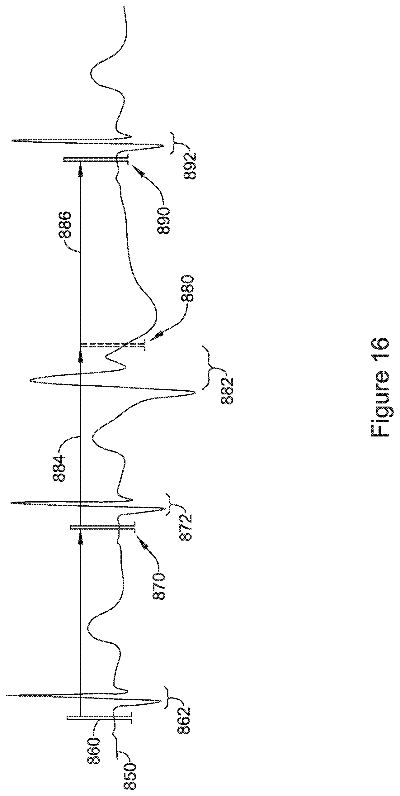
XML
uspto.report is an independent third-party trademark research tool that is not affiliated, endorsed, or sponsored by the United States Patent and Trademark Office (USPTO) or any other governmental organization. The information provided by uspto.report is based on publicly available data at the time of writing and is intended for informational purposes only.
While we strive to provide accurate and up-to-date information, we do not guarantee the accuracy, completeness, reliability, or suitability of the information displayed on this site. The use of this site is at your own risk. Any reliance you place on such information is therefore strictly at your own risk.
All official trademark data, including owner information, should be verified by visiting the official USPTO website at www.uspto.gov. This site is not intended to replace professional legal advice and should not be used as a substitute for consulting with a legal professional who is knowledgeable about trademark law.