Application container
Tani December 22, 2
U.S. patent number 10,869,532 [Application Number 16/254,110] was granted by the patent office on 2020-12-22 for application container. The grantee listed for this patent is TOKIWA CORPORATION. Invention is credited to Yoshikazu Tani.


View All Diagrams
| United States Patent | 10,869,532 |
| Tani | December 22, 2020 |
Application container
Abstract
An application container includes a cylindrical filling unit and a cover. The cover has a female screw formed at one end of the cover in the axial direction. The application container includes a main body that has an application tool that is configured to be inserted into the filling unit, and a male screw that is configured to be screwed into the female screw. Additionally, the application container includes a soft material wiper that is fixed to the opening of the filling unit. The wiper has a first protruding portion which protrudes outward from the opening in a radial direction of the filling unit to contact an inner surface of the cover. The first protruding portion is interposed in the axial direction between a wall portion disposed on the inner surface of the cover and the end of the filling unit which includes the opening.
| Inventors: | Tani; Yoshikazu (Kawaguchi, JP) | ||||||||||
|---|---|---|---|---|---|---|---|---|---|---|---|
| Applicant: |
|
||||||||||
| Family ID: | 1000005255277 | ||||||||||
| Appl. No.: | 16/254,110 | ||||||||||
| Filed: | January 22, 2019 |
Prior Publication Data
| Document Identifier | Publication Date | |
|---|---|---|
| US 20190223576 A1 | Jul 25, 2019 | |
Foreign Application Priority Data
| Jan 23, 2018 [JP] | 2018-008829 | |||
| Current U.S. Class: | 1/1 |
| Current CPC Class: | A45D 34/04 (20130101); A45D 34/046 (20130101) |
| Current International Class: | A46B 17/08 (20060101); A45D 34/04 (20060101) |
| Field of Search: | ;401/121,75 |
References Cited [Referenced By]
U.S. Patent Documents
| 6270273 | August 2001 | Ohba |
| 7845871 | December 2010 | Thiebaut |
| 2009/0028627 | January 2009 | Gueret |
| 2017/0303663 | October 2017 | Kim |
| S60-151421 | Oct 1985 | JP | |||
| H9-070314 | Mar 1997 | JP | |||
| H10-174613 | Jun 1998 | JP | |||
| H11-244043 | Sep 1999 | JP | |||
| 2999135 | Jan 2000 | JP | |||
| 2000-037227 | Feb 2000 | JP | |||
| 2016-220972 | Dec 2016 | JP | |||
| 20-0365067 | Oct 2004 | KR | |||
Attorney, Agent or Firm: Soei Patent & Law Firm
Claims
What is claimed is:
1. An application container comprising: a cylindrical filling unit that has an opening in one end in an axial direction; a cover that has a cylindrical shape for accommodating the filling unit, and that has a female screw formed at one end of the cover in the axial direction; a main body that has an application tool that is configured to be inserted into the filling unit, and a male screw that is configured to be screwed into the female screw; and a soft material wiper that is fixed to the opening of the filling unit, wherein the wiper has a first protruding portion which protrudes outward from the opening in a radial direction of the filling unit to contact an inner surface of the cover, wherein the first protruding portion is interposed in the axial direction between a wall portion disposed on the inner surface of the cover and the end of the filling unit which includes the opening, and wherein the wiper has a second protruding portion which protrudes in the axial direction towards the end of the cover which includes the female screw.
2. The application container according to claim 1, wherein a plurality of wall portions are disposed on the inner surface of the cover along a circumferential direction of the cover.
3. The application container according to claim 1, further comprising: a bar-shaped application material that is located at an opposite end of the main body from the application tool, wherein the main body includes a feeding mechanism which feeds the bar-shaped application material in the axial direction.
4. The application container according to claim 1, wherein the cover is removably connectable to the main body via the female screw, and wherein the application tool is removed from the fitting unit through the wiper when the cover is removed from the main body.
5. An application container comprising: a cylindrical filling unit that has an opening in one end in an axial direction; a cover that has a cylindrical shape for accommodating the filling unit, and that has a female screw formed at one end of the cover in the axial direction; a main body that has an application tool that is configured to be inserted into the filling unit, and a male screw that is configured to be screwed into the female screw; and a soft material wiper that is fixed to the opening of the filling unit, wherein the wiper has a first protruding portion which protrudes outward from the opening in a radial direction of the filling unit to contact an inner surface of the cover, wherein the first protruding portion is interposed in the axial direction between a wall portion disposed on the inner surface of the cover and the end of the filling unit which includes the opening, and wherein a plurality of wall portions are disposed on the inner surface of the cover along a circumferential direction of the cover.
6. The application container according to claim 5, further comprising: a bar-shaped application material that is located at an opposite end of the main body from the application tool, wherein the main body includes a feeding mechanism which feeds the bar-shaped application material in the axial direction.
7. The application container according to claim 5, wherein the filling unit and the wiper are fixed to the cover to form a unitary accommodation portion that is removable from the main body via the female screw of the cover.
8. An application container comprising: a main body having an application tool to apply an application material; and an accommodation portion to accommodate the application material, wherein the accommodation portion is removably connectable to the main body, and wherein the accommodation portion includes: a cover that extends in a longitudinal direction, wherein the cover includes an open end to receive the application tool of the main body, a longitudinal wall that extends substantially in the longitudinal direction, and an inner wall portion that extends inwardly from the longitudinal wall; a filling unit that is fixed inside the cover, wherein the filling unit extends in the longitudinal direction inside the cover, wherein the filling unit includes a first end forming an opening to receive the application tool and a second end opposite the first end; and a wiper that is at least partially located between the first end of the filling unit and the inner wall portion of the cover, in the longitudinal direction, wherein the wiper includes a protrusion that extends from the opening at the first end of the filling unit, outwardly toward the longitudinal wall of the cover, and wherein the protrusion is interposed in the longitudinal direction between the first end of the filling unit and the inner wall portion of the cover.
9. The application container according to claim 8, wherein the wiper is mounted at the opening formed at the first end of the filling unit.
10. The application container according to claim 8, comprising a plurality of inner wall portions including the inner wall portion, wherein the plurality of inner wall portions are arranged along an inner periphery of the cover to position the protrusion of the wiper between the plurality of inner wall portions and the filling unit.
11. The application container according to claim 8, wherein the protrusion includes a first protruding portion that extends from the opening at the first end of the filling unit in a lateral direction that is orthogonal to the longitudinal direction toward the longitudinal wall of the cover, and a second protruding portion that extends from the first protruding portion in the longitudinal direction toward the opening of the cover.
12. The application container according to claim 11, wherein the inner wall portion of the cover extending from the longitudinal wall includes an inclined surface that extends inwardly away from the open end of the cover, to engage the second protruding portion of the wiper.
13. The application container according to claim 12, wherein the second protrusion includes an inclined surface to contact the inclined surface of the inner wall portion of the cover.
14. The application container according to claim 8, wherein the wiper includes an inward extension portion that extends from the first end of the filling unit inwardly into the opening of the filling unit to form a through-hole for the application tool of the main body.
15. The application container according to claim 8, wherein the second end of the filling unit is closed so as to form a container to store the application material.
16. The application container according to claim 8, wherein the filling unit includes a longitudinal inner surface that extends substantially linearly in the longitudinal direction, from the first end to the second end of the filling unit.
17. The application container according to claim 8, wherein the wiper is recessed relative to the open end of the cover, in the longitudinal direction.
18. The application container according to claim 17, wherein the main body includes a first screw thread, and wherein the cover includes a second screw thread located between the wiper and the open end, to engage the first screw thread on the main body.
19. The application container according to claim 8, wherein the wiper includes a flexible material.
Description
CROSS-REFERENCE TO RELATED APPLICATIONS
This application claim priority to Japanese Patent Application No. P2018-008829, filed Jan. 23, 2018, the entire contents of which are incorporated herein by reference.
TECHNICAL FIELD
Application containers and application tools.
BACKGROUND
Japanese Unexamined Patent Publication No. 10-174613 discloses a liquid cosmetic material application container for accommodating a liquid cosmetic material. The liquid cosmetic material application container includes a main body having an application tool, and a lid body having a tank filled with the liquid cosmetic material to be adhered to the application tool. A male screw is formed on an outer surface of the main body, and a female screw is formed on an inner surface of the lid body. The male screw is screwed into the female screw, thereby attaching the main body to the lid body.
An opening of the tank in the lid body has a cylindrical sealing member for sealing the tank. The sealing member includes a flange portion protruding outward in a radial direction. The sealing member is fixed to an interior of the lid body by interposing the flange portion between the opening of the tank and a compression coil spring. The sealing member is made of synthetic rubber, and internally has a through-hole having a substantially funnel shape. The application tool of the main body is inserted into the through-hole. In addition, if the application tool is inserted into the through-hole, an application tool holder located in a base of the application tool comes into contact with an outer edge of the through-hole. The through-hole is sealed with the sealing member by the application tool holder coming into contact with the outer edge of the through-hole.
Japanese Unexamined Patent Publication No. H9-70314 discloses a liquid cosmetic material application container. The liquid cosmetic material application container includes a hollow shaft cylinder whose leading end has an application tool and which extends in a bar shape, and a lid body that can be attached to the shaft cylinder by covering the application tool. In the liquid cosmetic material application container, a female screw formed on an inner surface of the lid body is screwed to a male screw formed on an outer surface of the shaft cylinder, thereby attaching the lid body to the shaft cylinder.
The lid body includes a cartridge-type tank for accommodating the liquid cosmetic material, and a cylindrical body combined with the cartridge-type tank. The application tool is inserted into the cartridge type tank. The cylindrical body internally has a liquid cosmetic material sealing member serving as a synthetic rubber-made packing having a small hole into which the application tool is inserted. The liquid cosmetic material sealing member includes a peripheral ridge and a flange portion which are formed on an outer peripheral surface. The peripheral ridge of the liquid cosmetic material sealing member engages with a peripheral groove of the cartridge-type tank, and the flange portion is biased against the cartridge-type tank side by a compression coil spring. Thereby the liquid cosmetic material sealing member is fixed to an interior of the cylindrical body.
SUMMARY
The liquid cosmetic material sealing member functions as a cylindrical wiper which wipes off a liquid cosmetic material excessively adhering to the application tool when the application tool is pulled out from the tank. The peripheral ridge of the wiper engages with the peripheral groove of the tank, and the flange portion is biased against the tank side by the compression coil spring. In a case where the wiper is biased against the tank side by the compression coil spring, and since the wiper is formed of a soft material such as synthetic rubber, when a force acting in an axial direction is applied to the wiper, the wiper is deformed. Consequently, there is a possibility that the wiper may fall into the tank. In this way, when the force is applied to the wiper in the axial direction, the wiper may be detached.
Example application containers which can prevent a wiper from being detached are disclosed herein.
An example application container includes a cylindrical shaped filling unit having a closed bottom in one end and that has an opening in the other end in an axial direction, and a cover that has a cylindrical shape for accommodating the filling unit, and that has a female screw formed on one end side of an inner surface in the axial direction. Additionally, the application container may include a main body that has an application tool to be inserted into the filling unit, and a male screw to be screwed into the female screw, and a soft material-made wiper to be fixed to the opening of the filling unit and the inner surface of the cover. The wiper has a first protruding portion which protrudes outward in a radial direction. The first protruding portion is interposed in the axial direction between a wall portion to be disposed on the inner surface of the cover and an end portion on the opening side of the filling unit.
In the application container, the cylindrical filling unit having the opening in the end in the axial direction is accommodated in the cylindrical cover, thereby appearing as a double cylindrical shape. The female screw is formed on the one end side of the inner surface of the cover in the axial direction, and the male screw is formed in the main body having the application tool to be inserted into the filling unit. In a state where the application tool is inserted into the filling unit, the male screw of the main body is screwed into the female screw of the inner surface of the cover, thereby mounting the main body on the cover. The soft material-made wiper is fixed to the opening of the filling unit and the inner surface of the cover. The wiper includes the first protruding portion which protrudes outward in the radial direction. In addition, the inner surface of the cover has the wall portion, and the first protruding portion of the wiper is interposed in the axial direction between the wall portion and the end portion on the opening side of the filling unit. The first protruding portion is fixed in an interposed state in the axial direction between the wall portion of the inner surface of the cover and the end portion on the opening side of the filling unit. Therefore, the first protruding portion of the wiper is interposed in the axial direction between the wall portion of the inner surface of the cover and the end portion of the filling unit. Accordingly, a configuration can be adopted in which a force acting in the axial direction is less likely to be applied to the first protruding portion of the wiper. As a result, a position of the wiper may be prevented from being misaligned with the inner surface of the cover and the filling unit. Therefore, the wiper may be prevented from being detached.
The wiper may have a second protruding portion which protrudes in the axial direction from a surface on the wall portion side. In this case, the second protruding portion enters the wall portion in the axial direction. Therefore, the second protruding portion may be prevented from slipping out of the wall portion. Accordingly, the wiper may be reliably prevented from being detached.
A plurality of the wall portions may be disposed on the inner surface of the cover along a circumferential direction. In this case, the first protruding portion of the wiper can be interposed between a plurality of the wall portions and the end portion of the filling unit. Therefore, even in a case where a plurality of the wall portions are intermittently formed along the circumferential direction, the wiper may be reliably prevented from being detached.
The application container may further include a bar-shaped application material that extends in the axial direction on a side opposite to the application tool of the main body. The main body may include a feeding mechanism which feeds the bar-shaped application material in the axial direction. In this case, the filling unit is internally filled with a liquid or powder application material, and the application container includes the bar-shaped application material. Accordingly, one application container can be provided with a plurality of application material types. The main body includes the feeding mechanism which feeds the bar-shaped application material on the side opposite to the application tool of the main body. In this manner, the bar-shaped application material can be fed to the side opposite to the application tool.
Accordingly, the wiper may be prevented from being detached.
BRIEF DESCRIPTION OF THE DRAWINGS
FIG. 1 is a side view illustrating an example application container according to a first group of embodiments.
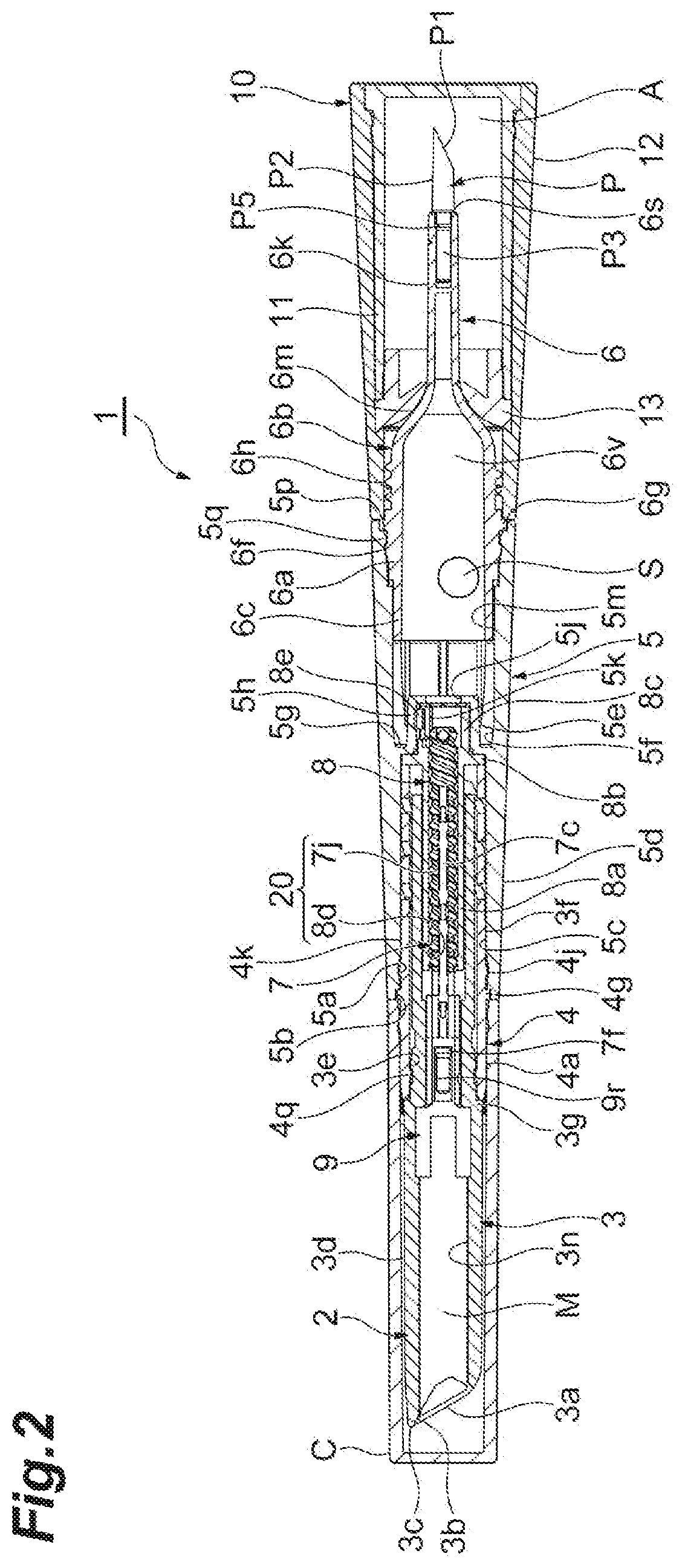
FIG. 2 is a sectional view taken along line A-A of the application container illustrated in FIG. 1.
FIG. 3 is a side view illustrating a state where an example cap is removed from the application container illustrated in FIG. 1.
FIG. 4 is a side view illustrating a state where an example bar-shaped application material is fed from the application container illustrated in FIG. 3.
FIG. 5 is a sectional view taken along line B-B of the application container illustrated in FIG. 4.
FIG. 6 is an enlarged sectional view illustrating a stepped cylindrical portion of an example leading cylinder in the application container illustrated in FIG. 5.
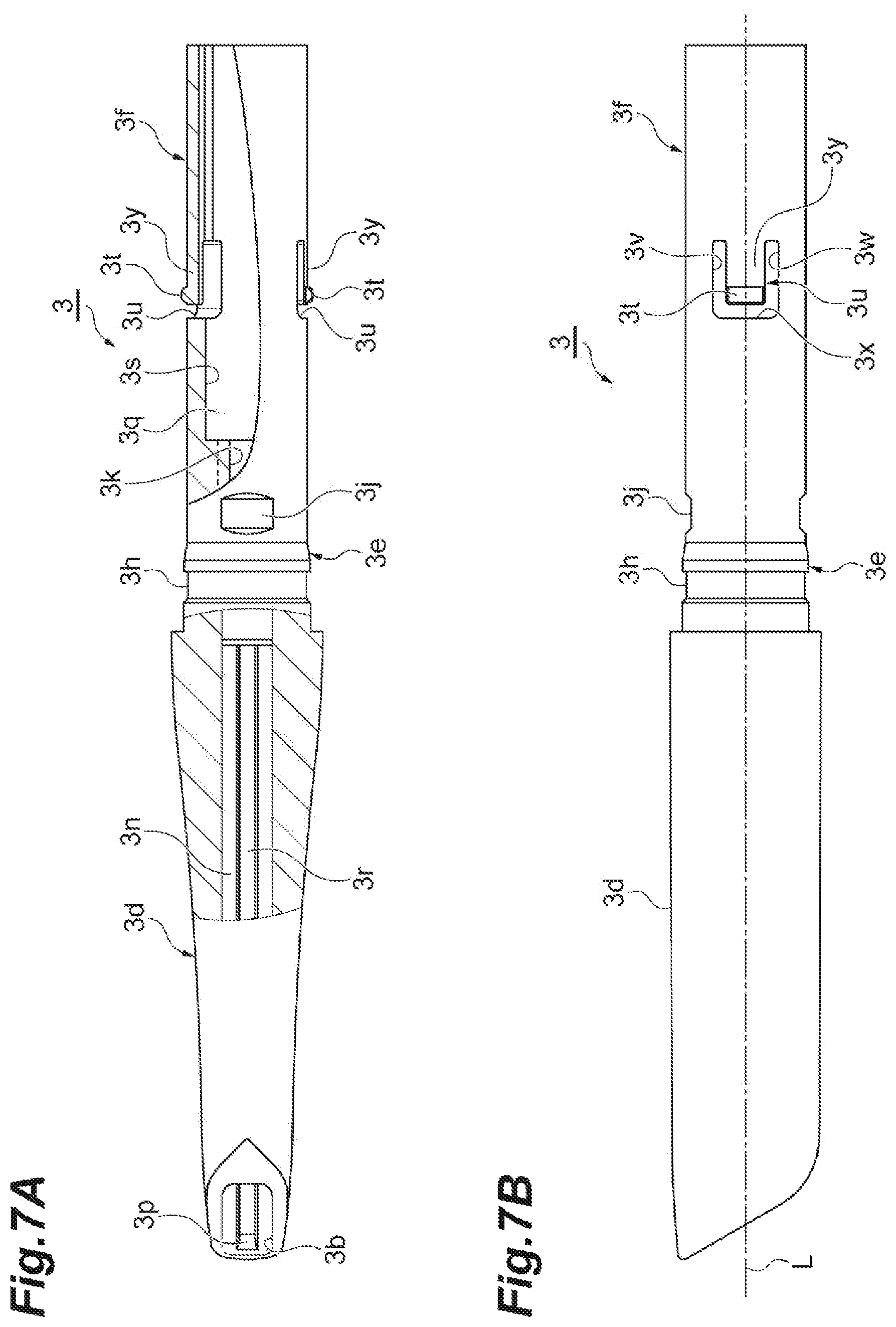
FIG. 7A is a partial sectional view illustrating the leading cylinder of the application container illustrated in FIG. 5.
FIG. 7B is a side view illustrating the leading cylinder of the application container illustrated in FIG. 5.
FIG. 8A is a side view illustrating an example middle cylinder of the application container illustrated in FIG. 4.
FIG. 8B is a side view when the middle container of the application container illustrated in FIG. 4 is viewed in a different rotational position from that of FIG. 8A.
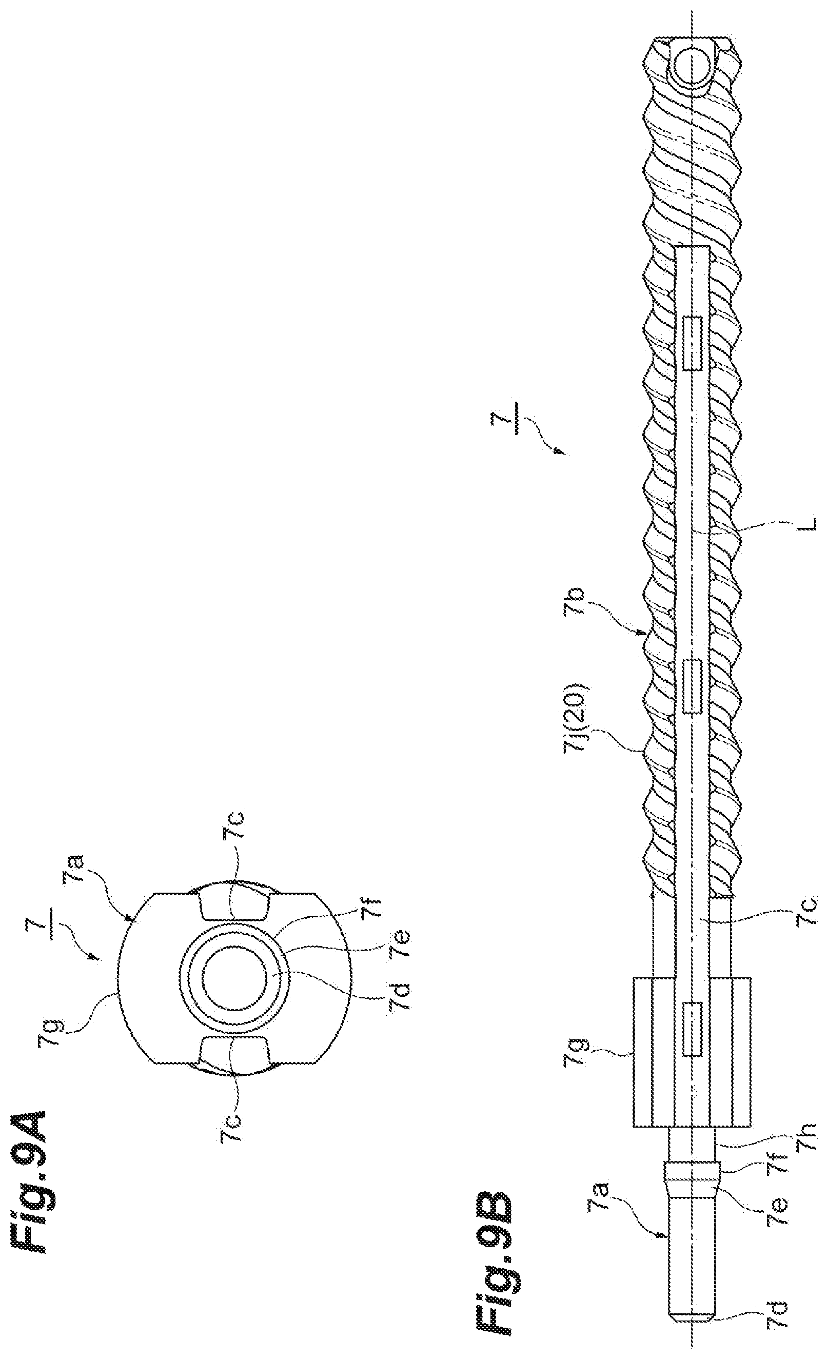
FIG. 9A is a front view when an example moving body of the application container illustrated in FIG. 5 is viewed from a front side in an axial direction.
FIG. 9B is a side view illustrating the moving body of the application container illustrated in FIG. 5.
FIG. 10A is a side view illustrating an example application material holder of the application container illustrated in FIG. 2.
FIG. 10B is a front view when the application material holder illustrated in FIG. 10A is viewed from the front side in the axial direction.
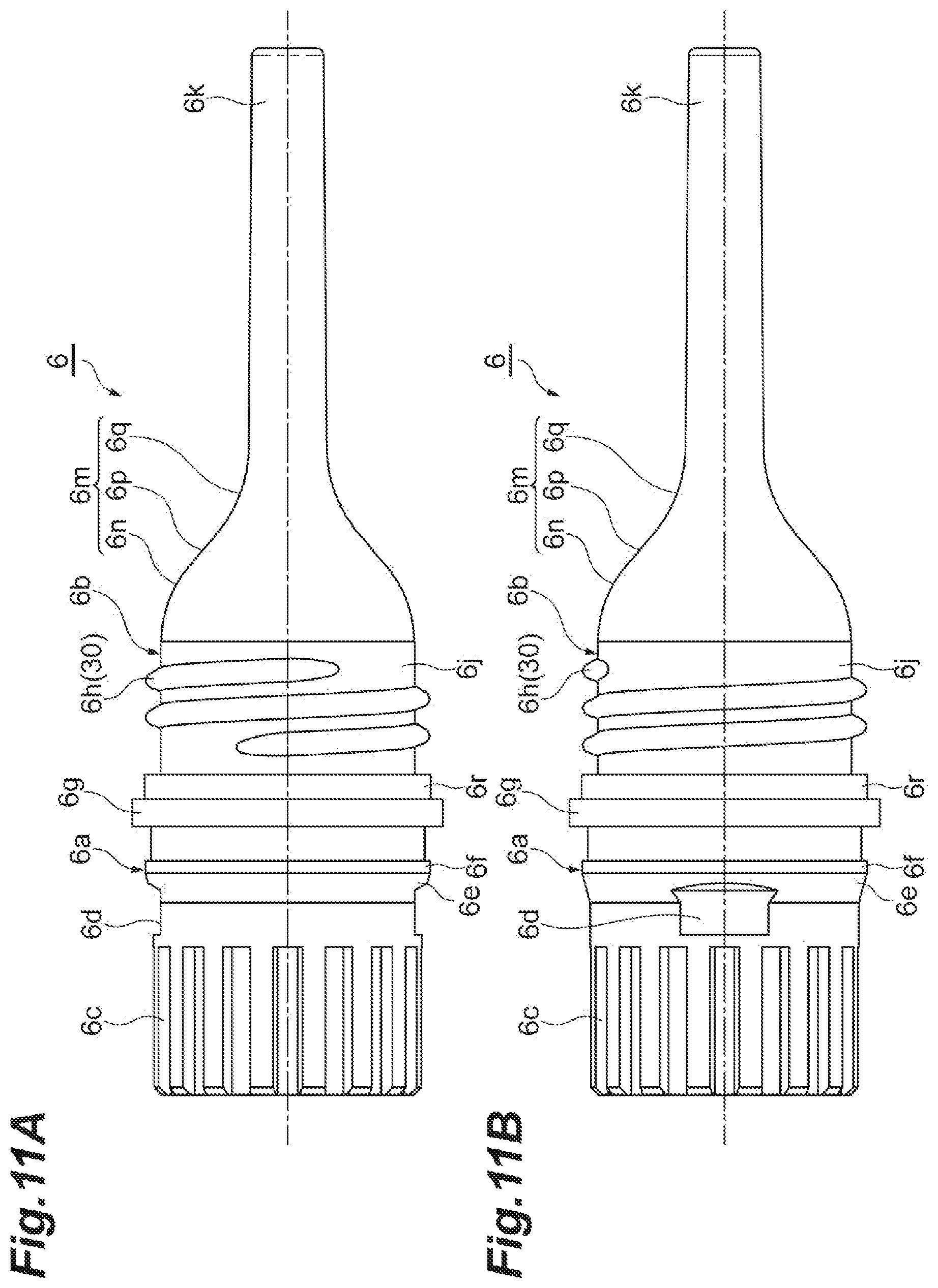
FIG. 11A is a side view illustrating an example attachment member of the application container illustrated in FIG. 4.
FIG. 11B is a side view when the attachment member of the application container illustrated in FIG. 4 is viewed in a direction different from that of FIG. 11A.
FIG. 12 is a side view illustrating an example filling unit of the application container illustrated in FIG. 2.
FIG. 13A is a side view illustrating an example wiper of the application container illustrated in FIG. 2.
FIG. 13B is a view when the wiper of the application container illustrated in FIG. 2 is viewed from a rear side in the axial direction.
FIG. 14 is a sectional view taken along line C-C of the wiper illustrated in FIG. 13A.
FIG. 15A is a partial sectional view illustrating an example cover of the application container illustrated in FIG. 2.
FIG. 15B is a longitudinal sectional view when the cover of the application container illustrated in FIG. 2 is cut along a plane including the axial direction.
FIG. 16 is an enlarged view illustrating an example wall portion of the cover illustrated in FIGS. 15A and 15B.
FIG. 17A is a longitudinal sectional view illustrating the filling unit, the cover, and the wiper.
FIG. 17B is an enlarged sectional view illustrating the wiper interposed between the filling unit and the wall portion of the cover in FIG. 17A.
FIG. 18A is a partial sectional view illustrating a cover of an example application container according to a second group of embodiments.
FIG. 18B is an enlarged sectional view illustrating a wall portion of the cover illustrated in FIG. 18A.
FIG. 19A is a longitudinal sectional view illustrating the cover, an example filling unit, and an example wiper illustrated in FIGS. 18A and 18B.
FIG. 19B is an enlarged sectional view illustrating the wiper interposed between the filling unit and the wall portion of the cover in FIG. 19A.
FIG. 20A is a partial sectional view illustrating a cover of an example application container according to a third group of embodiments.
FIG. 20B is an enlarged sectional view illustrating a wall portion of the cover illustrated in FIG. 20A.
FIG. 21A is a longitudinal sectional view illustrating the cover, an example filling unit, and an example wiper which are illustrated in FIGS. 20A and 20B.
FIG. 21B is an enlarged sectional view illustrating the wiper interposed between the filling unit and the wall portion of the cover in FIG. 21A.
DETAILED DESCRIPTION
Hereinafter, embodiments of an application container will be described with reference to the drawings. In describing the drawings, the same reference numerals will be given to the same or equivalent elements, and repeated description will be appropriately omitted.
First Group of Embodiments
FIGS. 1 and 2 illustrate an external view of an application container 1 according to a first group of embodiments having an overall shape which is an elongated round bar shaped like a writing tool. A cap C is attached thereto. The application container 1 includes a solid bar-shaped application material M. For example, the bar-shaped application material M is a bar-shaped cosmetic material, but may be a drawing material. In some examples, the bar-shaped application material M may be an eyebrow pencil. In the example illustrated in FIGS. 1 and 2, the application container 1 is an eyebrow feeding container.
For example, the application container 1 includes a main body 2 to which the cap C is attached, and an accommodation portion 10 which may be attached to a side opposite to the cap C of the main body 2 and accommodating the application material A. The application material A may be a powder or liquid application material. For example, the application material A may include a liquid or powder used for an eyeliner, an eye color, an eyebrow cosmetic, a mascara, a concealer, a lip color, or a hair color. Alternatively, the application material A may include a liquid or powder used for stationery goods including a writing tool, a correction fluid, or an adhesive.
In the application container 1, the cap C, the main body 2, and the accommodation portion 10 are arranged side by side along an axial direction in which an axis L of the application container 1 extends. In the description herein, an "axis" indicates a center line extending forward to and rearward from the application container 1. An "axial direction" is a forward-rearward direction, and indicates a direction along the axis L. A feeding direction of the bar-shaped application material M is defined as a forward direction (forward moving direction), and a direction opposite thereto is defined as a rearward direction.
FIG. 3 is a side view illustrating the application container 1 from which the cap C is removed. FIG. 4 is a side view illustrating a state where the bar-shaped application material M is fed by removing the accommodation portion 10 from the application container 1 illustrated in FIG. 3. FIG. 5 is a sectional view taken along line B-B in FIG. 4. As illustrated in FIGS. 3 to 5, the main body 2 includes a leading cylinder 3 forming a front portion of a container, a middle cylinder 4 disposed behind the leading cylinder 3, and a coupling cylinder 5 forming a rear portion of the container disposed behind the middle cylinder 4 and exposed outward of the application container 1. Additionally, the main body 2 may include an attachment member 6 extending rearward from the coupling cylinder 5 and to which the application tool P is attached, a moving body 7 accommodated inside the leading cylinder 3, a holding member 8 for holding the moving body 7 inside the coupling cylinder 5, and an application material holder 9 for holding the bar-shaped application material M on a front side of the moving body 7. The leading cylinder 3, the middle cylinder 4, the coupling cylinder 5, the moving body 7, and the holding member 8 may be assembled together to form a feeding mechanism 15 which feeds the bar-shaped application material M in the axial direction.
The bar-shaped application material M has a side surface M3 extending in the axial direction, and a leading end thereof has an inclined portion M1 inclined with respect to the axial direction. A shape of the bar-shaped application material M when viewed from the front side is formed so that the inclined portion M1 extends lengthwise or linearly in a uniform direction. In addition, a flat surface M2 extending in a direction inclined with respect to the axial direction is formed between the inclined portion M1 located in the leading end of the bar-shaped application material M and the side surface M3 of the bar-shaped application material M. For example, a pair of the flat surfaces M2 is disposed on both right and left sides with respect to the inclined portion M1. For example, each of the flat surfaces M2 extends rearward from both sides of the inclined portion M1 in a longitudinal direction. When the inclined portion M1 and a pair of the flat surfaces M2 are viewed from the front side, a shape thereof extends lengthwise or linearly in a uniform direction, and forms a rounded hexagonal shape.
For example, the leading cylinder 3 is molded using an ABS resin, and appears as an elongated cylindrical shape extending in the axial direction. An interior of the leading cylinder 3 serves as an accommodation space 3n for accommodating the bar-shaped application material M. A front end 3c of the leading cylinder 3 has an inclined surface 3a inclined with respect to the axial direction. An opening 3b from which the bar-shaped application material M is exposed is formed in the front end 3c of the leading cylinder 3. The opening 3b extends obliquely rearward from the front end 3c of the leading cylinder 3.
The leading cylinder 3 has a front side cylindrical portion 3d for accommodating the bar-shaped application material M, a stepped cylindrical portion 3e located behind the front side cylindrical portion 3d, and a rear side cylindrical portion 3f located behind the stepped cylindrical portion 3e. Among the front side cylindrical portion 3d, the stepped cylindrical portion 3e, and the rear side cylindrical portion 3f, in some examples only the front side cylindrical portion 3d is exposed outward. The front side cylindrical portion 3d gradually decreases in diameter from a step 3g toward the front end 3c. The step 3g is formed between the front side cylindrical portion 3d and the stepped cylindrical portion 3e, and the front side cylindrical portion 3d increases in diameter from the step 3g with respect to the stepped cylindrical portion 3e. A side behind the step 3g of the leading cylinder 3 serves as an insertion portion to be inserted into the middle cylinder 4 from the front side. The side behind the step 3g is inserted into the middle cylinder 4. In this manner, the leading cylinder 3 engages with the middle cylinder 4 so as to be immovable in the axial direction and relatively rotatable.
FIG. 6 is a sectional view in which the stepped cylindrical portion 3e of the leading cylinder 3 is cut along a plane including the axial direction. FIG. 7A is a partial sectional view of the leading cylinder 3. FIG. 7B is a side view of the leading cylinder 3. As illustrated in FIGS. 6, 7A, and 7B, inside the front side cylindrical portion 3d of the leading cylinder 3, the accommodation space 3n for accommodating the bar-shaped application material M extends along the axial direction. A shape of the accommodation space 3n when viewed along the axial direction is a non-circular shape. For example, the shape extends lengthwise or linearly in a uniform direction. A projection portion 3r extending in the axial direction is disposed inside the front side cylindrical portion 3d of the leading cylinder 3. For example, a pair of the projection portions 3r is disposed along the radial direction of the leading cylinder 3.
A front end of the projection portion 3r leads to the vicinity of the opening 3b of the leading cylinder 3, and the front end of the projection portion 3r has an inclined surface 3p which protrudes by being curved inward of the leading cylinder 3 as the inclined surface 3p is oriented rearward. An outer surface of the stepped cylindrical portion 3e of the leading cylinder 3 has an annular recess portion 3h extending in the circumferential direction of the leading cylinder 3, and a recess portion 3j located behind the annular recess portion 3h. When the leading cylinder 3 is manufactured by means of molding, an injection port for injecting a resin material into a molding die may be located at the center of the recess portion 3j. In some examples, a pair of the recess portions 3j is disposed along the radial direction of the leading cylinder 3, and each of the recess portions 3j has a rectangular shape.
A ridge 3k extending in the axial direction is disposed inside the stepped cylindrical portion 3e of the leading cylinder 3. For example, a plurality of the ridges 3k are disposed therein. Each of the ridges 3k extends from the rear side of the stepped cylindrical portion 3e to an inner surface of the rear side cylindrical portion 3f. For example, a pair of the ridges 3k is disposed along the radial direction of the leading cylinder 3. The rear side of the accommodation space 3n for accommodating the bar-shaped application material M has a tapered surface 3m inclined rearward as the tapered surface 3m is oriented inward in the radial direction.
The rear side of the ridge 3k serves as an internal space 3q of the rear side cylindrical portion 3f, and the internal space 3q has a larger diameter than a portion having the ridge 3k. The rear side cylindrical portion 3f includes an elastic protruding portion 3t at a pair of positions facing each other on an inner peripheral surface 3s thereof. The elastic protruding portion 3t comes into contact with the inner surface of the middle cylinder 4 by using an elastic force, and is disposed so as to protrude outward in the radial direction. A notch 3u allowing the inside and the outside of the leading cylinder 3 to communicate with each other is formed around the elastic protruding portion 3t. The elastic protruding portion 3t is caused to have elasticity in the radial direction by the notch 3u.
The notch 3u includes a pair of slits 3v and 3w which are arranged side by side at a plurality of positions along the circumferential direction of the leading cylinder 3 and which extend in the axial direction. Additionally, the notch 3u includes a slit 3x drilled on the front side of the elastic protruding portion 3t and extending in the circumferential direction of the leading cylinder 3 between the slits 3v and 3w. A portion surrounded by the notch 3u in the rear side cylindrical portion 3f forms an arm 3y which is flexible in the radial direction. Accordingly, the elastic protruding portion 3t located on the outer surface of the leading end portion of the arm 3y has an elastic force (biasing force) acting in the radial direction.
The annular projection 4q on the inner surface of the middle cylinder 4 may be configured to engage with the stepped cylindrical portion 3e of the leading cylinder 3 in the axial direction so that the stepped cylindrical portion 3e and the annular projection 4q are relatively rotatable, and the elastic protruding portion 3t comes into contact with the inner surface of the middle cylinder 4. FIG. 8A is a side view illustrating the middle cylinder 4, and FIG. 8B is a side view when the middle cylinder 4 is viewed in a rotational position different from that in FIG. 8A. In some examples, the middle cylinder 4 is molded using polyacetal (POM), and is formed into a substantially cylindrical shape.
As illustrated in FIGS. 8A and 8B, the middle cylinder 4 includes a front side cylindrical portion 4a, a rear side cylindrical portion 4b, and a spring portion 4c in this order from the front end toward the rear end. The middle cylinder 4 softens an impact internally transmitted when an external force is applied such as during falling, thereby protecting the application container 1 or the bar-shaped application material M. The spring portion 4c of the middle cylinder 4 has a function to screw back the screw portion 20 when a clutch is rotated up to the rearward movement limit of the bar-shaped application material M. The front end portion on the outer peripheral surface of the front side cylindrical portion 4a has an inclined surface 4f which gradually increases in diameter as the inclined surface 4f is oriented rearward. The outer peripheral surface of the front side cylindrical portion 4a has a protruding portion 4d extending in the axial direction, and a projection 4e protruding in a substantially circular shape behind the protruding portion 4d. The cap C engages with the protruding portion 4d and the projection 4e.
A flange portion 4g protruding outward in the radial direction and entering the front end of the coupling cylinder 5 is disposed between the front side cylindrical portion 4a and the rear side cylindrical portion 4b. The outer surface of the rear side cylindrical portion 4b has an annular projection 4j having an inclined surface 4h which decreases in diameter in the rearward direction, a plurality of protruding portions 4k extending in the axial direction behind the annular projection 4j and that are arranged side by side along the circumferential direction of the middle cylinder 4, and a recess portion 4m recessed between a plurality of the protruding portions 4k. When the middle cylinder 4 is manufactured by means of molding, an injection port for injecting a resin material such into a molding die may be located at the center of the recess portion 4m. The spring portion 4c is disposed behind the protruding portion 4k and the recess portion 4m. The spring portion 4c is a resin spring which is stretchable in the axial direction. The spring portion 4c is formed to have a main body portion 4n and a slit 4p which spirally extends along a peripheral surface of the main body portion 4n and which allows the inside and the outside of the main body portion 4n to communicate with each other. The spring portion 4c softens an impact by compressing when an external force is applied thereto.
As illustrated in FIGS. 2 and 5, in the middle cylinder 4, a portion on the rear side of the front side cylindrical portion 4a is inserted into the front side of the coupling cylinder 5. In addition, in the middle cylinder 4, the annular projection 4j engages with the annular recess portion 5a disposed on the inner surface of the coupling cylinder 5 in the axial direction, and the flange portion 4g fits into the recess portion 5b in the front end of the coupling cylinder 5. A knurling tool 5c for engaging with the middle cylinder 4 in the rotation direction is disposed on the rear side of the annular recess portion 5a of the coupling cylinder 5. The knurling tool 5c is formed in a shape where a plurality of irregularities are arranged side by side along the circumferential direction and the respective irregularities extend in the axial direction. The protruding portion 4k of the middle cylinder 4 engages with the knurling tool 5c in the rotation direction. In this manner, the middle cylinder 4 engages with the coupling cylinder 5 so as to be synchronously rotatable.
For example, the coupling cylinder 5 is molded using an ABS resin, and is formed in a cylindrical shape. The outer surface of the coupling cylinder 5 serves as a smooth surface having no irregularities. In some examples, the outer surface is an inclined surface 5d which gradually increases in diameter in a rearward direction. The holding member 8 and the middle cylinder 4 are accommodated on the front side of the coupling cylinder 5, and the attachment member 6 is accommodated on the rear side of the coupling cylinder 5. The coupling cylinder 5 includes a partition wall 5e which partitions the interior of the coupling cylinder 5 in the vicinity of the center in the axial direction. The holding member 8 and the middle cylinder 4 are inserted forward of the partition wall 5e, and the attachment member 6 is inserted rearward of the partition wall 5e.
The partition wall 5e has a protruding portion 5g protruding inward in the radial direction of the coupling cylinder 5 from the inner surface 5f of the coupling cylinder 5, a recess portion 5h recessed rearward from an end portion inside the protruding portion 5g in the radial direction, and a through-hole 5j penetrating in the axial direction on a bottom surface of the recess portion 5h. The inner surface of the recess portion 5h has a knurling tool 5k in which a plurality of irregularities are arranged side by side along the circumferential direction and the respective irregularities extend in the axial direction. The inner surface 5f on the rear side of the partition wall 5e has a larger diameter than the inner surface 5f on the front side of the partition wall 5e.
For example, the holding member 8 is molded using a POM, and is formed into a substantially cylindrical shape. The holding member 8 has a front side cylindrical portion 8a extending in the axial direction, a flange portion 8b which increases in diameter in the rear end of the front side cylindrical portion 8a, and a rear side cylindrical portion 8c engaging with the knurling tool 5k of the recess portion 5h of the coupling cylinder 5, which is a rear side portion of the flange portion 8b. The inner surface of the front end portion of the front side cylindrical portion 8a has a spiral projection 8d forming one side of the screw portion 20 (described in further detail later).
The flange portion 8b of the holding member 8 is interposed between the protruding portion 5g of the partition wall 5e of the coupling cylinder 5 and the rear end of the middle cylinder 4. The rear side cylindrical portion 8c of the holding member 8 includes an elastic protruding portion 8e. The elastic protruding portion 8e engages with the knurling tool 5k of the coupling cylinder 5 in the rotation direction, and is disposed so as to protrude outward in the radial direction. A notch 8f which allows the inside and the outside of the holding member 8 to communicate with each other is formed around the elastic protruding portion 8e. The notch 8f causes the elastic protruding portion 8e to be elastic in the radial direction. For example, a configuration of the notch 8f may be similar to a configuration of the notch 3u of the leading cylinder 3.
In some example holding members 8, the rear side cylindrical portion 8c is inserted into the recess portion 5h of the partition wall 5e from the front side, and the elastic protruding portion 8e engages with the knurling tool 5k of the recess portion 5h in the rotation direction. The elastic protruding portion 8e and the knurling tool 5k enable the holding member 8 to be synchronously rotatable around the axis with respect to the coupling cylinder 5, and can release the synchronous rotation when a prescribed or greater rotational force (torque) is applied thereto. Since the synchronous rotation is released, the bar-shaped application material M reaches a forward movement limit, and a screwing operation of the screw portion 20 is stopped. Thereafter, the leading cylinder 3 or the middle cylinder 4 may be prevented from being disassembled due to a force of relatively rotating the leading cylinder 3 and the coupling cylinder 5. In addition, in the holding member 8, the flange portion 8b is interposed between the partition wall 5e and the middle cylinder 4 in the axial direction. In this manner, the holding member 8 engages with the coupling cylinder 5 so as to be linearly immovable in the axial direction and synchronously rotatable. In addition, the moving body 7 is inserted into the front side cylindrical portion 8a of the holding member 8.
FIG. 9A is a front view when the moving body 7 is viewed from the front side, and FIG. 9B is a side view of the moving body 7. In some examples, the moving body 7 is molded using a POM, and is formed into a round bar shape. The moving body 7 includes a connector 7a disposed on the front side and connected to the application material holder 9, and a shaft body portion 7b extending rearward from the connector 7a. The outer surface of the connector 7a and the outer surface of the shaft body portion 7b have a groove portion 7c extending in the axial direction. The groove portion 7c functions as a detent for the moving body 7 against the leading cylinder 3, together with the ridge 3k disposed on the inner surface of the leading cylinder 3. For example, a pair of the groove portions 7c is disposed in the radial direction of the moving body 7.
The front end of the connector 7a of the moving body 7 has a tapered surface 7d which increases in diameter in the rearward direction. The connector 7a has an annular projection 7f having a tapered surface 7e which gradually increases in diameter in the rearward direction behind the tapered surface 7d, and an enlarged diameter portion 7g having a larger diameter than the annular projection 7f behind the annular projection 7f. A portion between the annular projection 7f and the enlarged diameter portion 7g serves as a reduced diameter portion 7h which has a decreased diameter relative to the annular projection 7f and the enlarged diameter portion 7g.
The shaft body portion 7b is a shaft body extending from the rear end of the connector 7a in the axial direction. The outer surface of the shaft body portion 7b has a male screw 7j forming the other one of the screw portion 20. The male screw 7j is formed throughout the axial direction of the shaft body portion 7b. In some examples, the annular projection 7f is inserted into the application material holder 9, and the front end of the enlarged diameter portion 7g comes into contact with the rear end of the application material holder 9. In this manner, the moving body 7 engages with the application material holder 9 in the axial direction. The groove portion 7c of the moving body 7 engages with the ridge 3k which is formed on the inner surface of the leading cylinder 3 in the rotation direction. The moving body 7 is inserted into the front side of the holding member 8, and the male screw 7j is screwed to the projection 8d of the holding member 8 forming one side of the screw portion 20.
FIG. 10A is a side view illustrating the application material holder 9. FIG. 10B is a front view when the application material holder 9 is viewed from the front side. The application material holder 9 is a core chuck push bar internally inserted into the leading cylinder 3 so as to hold the bar-shaped application material M. For example, a material of the application material holder 9 is polybutylene terephthalate (PBT). As illustrated in FIGS. 10A and 10B, the application material holder 9 includes a gripper 9a located on the front side so as to grip the bar-shaped application material M, and a support portion 9b extending rearward from the gripper 9a and supporting the moving body 7. A shape of the application material holder 9 when viewed along the axial direction is a non-circular shape. For example, the application material holder 9 has a rectangular shape in which corner portions are rounded and which extends lengthwise in one direction.
The gripper 9a includes a base portion 9c forming a connector between the gripper 9a and the support portion 9b, and a plurality of arms 9d extending forward from the base portion 9c and gripping the bar-shaped application material M. The bar-shaped application material M is gripped inside a plurality of the arms 9d. The inner surface of the respective arms 9d has a protruding portion 9e extending in the axial direction along the arm 9d. Each protruding portion 9e fits into the bar-shaped application material M, thereby allowing the bar-shaped application material M to be properly held by the application material holder 9.
A shape of each protruding portion 9e when viewed along the axial direction is a triangular shape whose leading end is rounded. Each arm 9d decreases in thickness in a forward direction. In some examples, each arm 9d has a first inclined surface 9g and a second inclined surface 9j sequentially forward from the base portion 9c. One or more portions of the application material holder 9 may extend in the axial direction. For example, a portion between the base portion 9c and the first inclined surface 9g of the atm 9d, a portion between the first inclined surface 9g and the second inclined surface 9j of the atm 9d, and a portion between the second inclined surface 9j and the front end 9k of the arm 9d may extend in the axial direction.
The thickness of the arm 9d between the base portion 9c and the first inclined surface 9g is greater than the thickness of the arm 9d between the first inclined surface 9g and the second inclined surface 9j. The thickness of the arm 9d between the first inclined surface 9g and the second inclined surface 9j is greater than the thickness of the atm 9d between the second inclined surface 9j and the front end 9k. The height of the protruding portion 9e of the arm 9d is constant along the axial direction. Accordingly, a protruding height of the protruding portion 9e relative to a top surface of the first inclined surface 9g is lower than a protruding height of the protruding portion 9e relative to a top surface of the second inclined surface 9j.
The support portion 9b of the application material holder 9 extends from the base portion 9c to a side opposite to the gripper 9a (rearward), thereby forming a cylindrical shape having a closed bottom, for example. The support portion 9b has a recess portion 9q disposed on an outer surface thereof, a window portion 9r which allows the inside and the outside of the support portion 9b to communicate with each other, and a through-hole 9s disposed in the rear end of the application material holder 9 and penetrating the application material holder 9 in the axial direction. An injection port for injecting a resin material into a molding die when the application material holder 9 is manufactured by means of molding may be located at the center of the recess portion 9q. The rear end portion of the through-hole 9s has a tapered surface 9t which increases in diameter in a rearward direction. In some examples, the recess portion 9q has a circular shape, and the window portion 9r has a rectangular shape extending lengthwise in the axial direction. The window portion 9r and the through-hole 9s communicate with each other. The through-hole 9s when viewed from the rear has a circular shape.
In the application material holder 9, the moving body 7 is inserted into the through-hole 9s from behind. Additionally, the annular projection 7f of the moving body 7 rides over the inner surface of the through-hole 9s in the window portion 9r. The annular projection 7f fits into the window portion 9r, and is exposed outward from the window portion 9r. In this manner, the application material holder 9 engages with the moving body 7 so as to be immovable in the axial direction. The application material holder 9 having the non-circular shape enters the accommodation space 3n having the non-circular shape of the leading cylinder 3. In this manner, the application material holder 9 engages with the leading cylinder 3 in the rotation direction, and is synchronously rotated together with the leading cylinder 3.
The attachment member 6 is inserted into the rear side of the partition wall 5e of the coupling cylinder 5. FIG. 11A is a side view illustrating the attachment member 6, and FIG. 11B is a side view when the attachment member 6 is viewed from a rotational position different from that in FIG. 11A. The attachment member 6 may be formed of polypropylene (PP). As illustrated in FIGS. 11A and 11B, the attachment member 6 has a cylindrical shape which gradually decreases in diameter rearward from the front side. The attachment member 6 includes an insertion portion 6a located on the front side and inserted into the coupling cylinder 5, and an attachment portion 6b extending rearward from the insertion portion 6a and having the application tool P attached to the leading end.
The insertion portion 6a has a stepped cylindrical shape. The outer surface of the insertion portion 6a has a knurling tool 6c extending in the axial direction, a recess portion 6d disposed on the rear side of the knurling tool 6c, an annular projection portion 6f protruding from the recess portion 6d and having a tapered surface 6e on the front side, and a flange portion 6g which has a greater diameter behind the annular projection portion 6f. The attachment portion 6b includes a large diameter portion 6j having a male screw 6h forming one side of a screw portion 30 for mounting the accommodation portion 10 on the main body 2, and a small diameter portion 6k extending rearward from the large diameter portion 6j and to which the application tool P is attached.
Both the large diameter portion 6j and the small diameter portion 6k have a cylindrical shape extending in the axial direction. An enlarged diameter portion 6r which increases in diameter from the outer surface of the attachment member 6 having the male screw 6h is disposed in front of the male screw 6h of the large diameter portion 6j. The enlarged diameter portion 6r is disposed on the rear side of the flange portion 6g. The height protruding outward in the radial direction of the enlarged diameter portion 6r is lower than the height protruding outward in the radial direction of the flange portion 6g. An inclined surface 6m which gradually decreases in diameter from the large diameter portion 6j toward the small diameter portion 6k is disposed between the large diameter portion 6j and the small diameter portion 6k.
The inclined surface 6m has an arc-shaped first bending portion 6n having a center of rotation located inside in the radial direction of the attachment member 6, an inclined portion 6p located on a side opposite to the large diameter portion 6j of the first bending portion 6n, and an arc-shaped second bending portion 6q having a center of rotation located outside in the radial direction of the attachment member 6. The first bending portion 6n, the inclined portion 6p, and the second bending portion 6q are disposed in this order from the large diameter portion 6j toward the small diameter portion 6k. An inclination angle of the inclined portion 6p with respect to the axial direction is 36.degree., for example.
As illustrated in FIGS. 2 and 5, the attachment member 6 internally has a space 6v, and the space 6v accommodates a stirring member S for stirring the application material A. For example, a material of the stirring member S is SUS. However, the material may be a resin, and may be appropriately changed. The stirring member S is accommodated in a portion on the front side from the inclined surface 6m on the inner surface of the attachment member 6. For example, the stirring member S is a ball, and is formed into a spherical shape. The stirring member S emits sound by moving inside the space 6v in accordance with vibrations applied to the application container 1. The small diameter portion 6k of the attachment portion 6b extends rearward from the inclined surface 6m. The rear end of the small diameter portion 6k has an opening 6s into which the application tool P is inserted.
In the attachment member 6, the insertion portion 6a is inserted into the coupling cylinder 5 from behind, and the knurling tool 6c engages with the ridge 5m on the inner surface of the coupling cylinder 5 in the rotation direction. The annular projection portion 6f engages with the annular projection portion 5q on the inner surface of the coupling cylinder 5 in the axial direction. In this manner, the attachment member 6 engages with the coupling cylinder 5 so as to be immovable in the axial direction and non-rotatable. Then, the flange portion 6g of the attachment member 6 enters the annular recess portion 5p formed in the rear end of the coupling cylinder 5.
The application tool P has a round bar shape, and has an inclined surface P1 in one end in the longitudinal direction. The inclined surface P1 is disposed in the rear end of the main body 2, and is inclined so as to form an acute angle with respect to the axial direction. For example, the inclined surface P1 has a flat shape. The application tool P has a large diameter portion P2 having the inclined surface P1 and a small diameter portion P3 extending forward from the large diameter portion P2. The small diameter portion P3 is inserted into the opening 6s of the attachment member 6. The outer surface of the small diameter portion P3 has an annular projection portion P5 which causes the application tool P to engage with the attachment member 6 and which has a tapered surface on the front side. In the application tool P, the small diameter portion P3 is inserted into the opening 6s of the attachment member 6 from the rear side, and the annular projection portion P5 rides over the annular projection portion inside the opening 6s so as to move forward. In this manner, the application tool P engages with the attachment member 6 in the axial direction.
Next, the accommodation portion 10 attached to the attachment member 6 and accommodating the application material A will be described in additional detail. The accommodation portion 10 includes a cylindrical filling unit 11 having a closed bottom and filled with the application material A, a cover 12 surrounding the filling unit 11 and attached to the attachment member 6, and a soft material-made wiper 13 which draws the application tool P and the small diameter portion 6k of the attachment member 6 so as to wipe off the application material A excessively adhering to the application tool P and the small diameter portion 6k.
FIG. 12 is a side view illustrating the filling unit 11. For example, the filling unit 11 is formed of PP. As illustrated in FIG. 12, the filling unit 11 is formed in a cylindrical shape. The inner surface of the filling unit 11 has no irregularities, and serves as a smooth surface. The inner surface of the filling unit 11 is configured to include an inner surface 11a smoothly curved in a cylindrical hole shape, and a flat bottom surface 11b located in the rear end of the inner surface 11a.
The front side of the outer surface of the filling unit 11 has no irregularities, and serves as the smooth surface. The filling unit 11 has an opening 11h into which the wiper 13 is inserted in one end 11g on the front side. The rear side of the outer surface of the filling unit 11 includes an enlarged diameter portion 11c protruding outward in the radial direction in the rear end of the filling unit 11, an annular projection portion 11e located in front of the enlarged diameter portion 11c and having a tapered surface 11d on the front side, and a plurality of projection portions 1 if extending forward in the axial direction from the tapered surface 11d. The rear end of the enlarged diameter portion 11e is slightly rounded. In some examples, four of the projection portions 11f are disposed therein. The four projection portions 11f are disposed at an equal interval in the circumferential direction. For example, a protruding shape of the projection portion 11f is an arc shape.
FIG. 13A is a side view illustrating the wiper 13, and FIG. 13B is a view when the wiper 13 is viewed from the rear side. FIG. 14 is a sectional view taken along line C-C illustrated in FIG. 13A. The wiper 13 is formed of a rubber material. The hardness of the wiper 13 may be set to a value within the range of 40 to 80 in accordance with a type A durometer regulated in JIS 6253 (method of obtaining hardness of vulcanized rubber and thermoplastic rubber). For example, the hardness may be set to 60.
As illustrated in FIGS. 13A, 13B, and 14, the wiper 13 has a stepped cylindrical shape. The wiper 13 includes a cylindrical extension portion 13a extending rearward, a first protruding portion 13b protruding outward in the radial direction in the front end of the extension portion 13a, a second protruding portion 13c further protruding forward from the front end of the first protruding portion 13b, and a drawing portion 13d protruding inward in the radial direction from the extension portion 13a and the first protruding portion 13b.
The extension portion 13a has a first side surface 13e extending in the axial direction from the rear end of the first protruding portion 13b, a first tapered surface 13f inclined inward in the radial direction of the wiper 13 from the rear end of the first side surface 13e, a second side surface 13g extending in the axial direction from the rear end of the first tapered surface 13f, and a second tapered surface 13h inclined inward in the radial direction of the wiper 13 from the rear end of the second side surface 13g. The rear end of the second tapered surface 13h corresponds to the rear end of the wiper 13.
The wiper 13 has a through-hole 13r into which the application tool P and the attachment member 6 are inserted, and the through-hole 13r penetrates the wiper 13 in the axial direction. The inner surface of the extension portion 13a of the wiper 13 is configured to include an inner peripheral surface 13j smoothly curved in a cylindrical hole shape, and the drawing portion 13d protruding inward in the radial direction from the front end of the inner peripheral surface 13j. The drawing portion 13d includes a first planar portion 13k located in the front end of the inner peripheral surface 13j, a first extension portion 13m extending inward in the radial direction from an end portion of the first planar portion 13k, an annular portion 13n located in the rear end of the first extension portion 13m, an inner peripheral surface 13p extending forward from the annular portion 13n, and a bending portion 13q extending from the front end of the inner peripheral surface 13p toward the first protruding portion 13b.
The first planar portion 13k extends inward in the radial direction from the front end of the inner peripheral surface 13j. The first extension portion 13m obliquely extends rearward and inward in the radial direction from an end portion of the first planar portion 13k. The annular portion 13n is formed in a flat shape in the rear end of the first extension portion 13m. The inner peripheral surface 13p extends forward and inward in the radial direction from an end portion of the annular portion 13n. The bending portion 13q faces the first protruding portion 13b from the front end of the inner peripheral surface 13p, and is bent forward and outward in the radial direction so that the drawing portion 13d bulges. The application tool P and the attachment member 6 which are to be inserted into the through-hole 13r come into contact with the bending portion 13q and the inner peripheral surface 13p, and move rearward. The attachment member 6 and the application tool P which are drawn forward from the through-hole 13r are drawn while both of these mainly come into contact with the inner peripheral surface 13p. In this manner, both the attachment member 6 and the application tool P are drawn by the wiper 13.
The first protruding portion 13b has a protruding surface 13s extending outward in the radial direction from the front end of the extension portion 13a, an outer peripheral surface 13t extending forward from an end portion of the protruding surface 13s outside in the radial direction, and a tapered surface 13z which decreases in diameter from the front end of the outer peripheral surface 13t. The second protruding portion 13c has a protruding surface 13u extending forward, an annular surface 13v extending inward in the radial direction from the front end of the protruding surface 13u, and an inclined surface 13w extending rearward from an end portion of the annular surface 13v and obliquely extending inward in the radial direction.
FIG. 15A is a partial sectional view illustrating the cover 12, and FIG. 15B is a longitudinal sectional view when the cover 12 is cut along a plane including the axis L. The cover 12 has a cylindrical shape, and is formed of an ABS resin, for example. The cover 12 may have a cylindrical shape. The outer surface of the cover 12 serves as a smooth surface having no irregularities. In some examples, the outer surface is an inclined surface 12a which gradually increases in diameter in a rearward direction. The rear end of the inclined surface 12a (rear end of the cover 12) has a bending portion 12b which extends while being bent inward in the radial direction from the inclined surface 12a and which is rounded.
The rear side of the inner surface 12q of the cover 12 has an annular recess portion 12n extending forward from the rear end 12m of the cover 12, and an annular irregular portion 12p located on the front side of the annular recess portion 12n. The vicinity at the center of the inner surface 12q of the cover 12 in the axial direction serves as a smooth surface 12c having no irregularities. An inclination angle of the inner surface 12q with respect to the axial direction is smaller than an inclination angle of the inclined surface 12a with respect to the axial direction. Therefore, the portion of the cover 12 having the inclined surface 12a and the inner surface 12q gradually becomes thicker in the rearward direction.
The front side of the inner surface 12q of the cover 12 has a wall portion 12d protruding inward in the radial direction from the smooth surface 12c, and a female screw 12e disposed in front of the wall portion 12d and forms the other side of the screw portion 30. The female screw 12e is configured to include a spiral projection 12f protruding inward in the radial direction from the inner surface 12q of the cover 12. The cover 12 is mounted on the attachment member 6 by screwing the projection 12f to the male screw 6h forming the one side of the screw portion 30.
FIG. 16 is an enlarged view of the wall portion 12d of the cover 12. As illustrated in FIGS. 15A, 15B, and 16, a plurality of the wall portions 12d are arranged side by side along the circumferential direction of the cover 12. In some examples, the wall portions 12d are intermittently formed along the circumferential direction of the cover 12. The wall portion 12d has a top surface 12g protruding inward in the radial direction as the top surface 12g is oriented rearward from the portion having the female screw 12e, a bending portion 12h folded outward in the radial direction and forward from the rear end of the top surface 12g, an inclined surface 12j obliquely extending outward in the radial direction and forward from the bending portion 12h, and a flat portion 12k extending further outward in the radial direction from an end portion of the inclined surface 12j.
In some examples, the plurality of wall portions 12d are arranged at an equal interval in the circumferential direction, and the number of the wall portions 12d is 12. The top surface 12g of the wall portions 12d extends along the axis L, and extends parallel to the axis L, for example. However, the top surface 12g may not extend parallel to the axis L. For example, the top surface 12g may be inclined in a direction away from the axis as the top surface 12g is oriented rearward.
FIG. 17A is a longitudinal sectional view when the accommodation portion 10 including the filling unit 11, the cover 12, and the wiper 13 are cut along a plane including the axis L. FIG. 17B is an enlarged sectional view illustrating the wall portion 12d, the first protruding portion 13b, and one end 11g of the filling unit 11 in FIG. 17A. In the wiper 13, the extension portion 13a is inserted into the opening 11h of the filling unit 11 from the front side. The whole first side surface 13e closely adheres to the inner surface 11a of the filling unit 11, and the protruding surface 13s of the first protruding portion 13b comes into contact with one end 11g.
The filling unit 11 having the wiper 13 mounted thereon may be inserted into the cover 12 from the rear side. The wiper 13 and the filling unit 11 which are inserted into the cover 12 are engaged with the cover 12 in the axial direction in a state where the second protruding portion 13c of the wiper 13 is in contact with the wall portion 12d of the cover 12 in the axial direction. In some examples, the filling unit 11 and the wiper 13 engage with the cover 12 in the axial direction by fitting the annular projection portion 11e into a recess portion of the annular irregular portion 12p of the cover 12. A position in the forward-rearward direction of the rear end 11j of the filling unit 11 engaging with the cover 12 in the axial direction substantially coincides with a position in the forward-rearward direction of the rear end 12m of the cover 12 (or located slightly forward of the rear end 12m).
Then, in the wiper 13 mounted on the filling unit 11, the annular surface 13v and the inclined surface 13w of the second protruding portion 13c enters the bending portion 12h and the inclined surface 12j of the wall portion 12d. In this manner, the wiper 13 is pressed against the cover 12 in the axial direction, and closely adheres to the wall portion 12d. The outer surface of the extension portion 13a, which is the portion excluding the first protruding portion 13b of the wiper 13, closely adheres to the inner surface 11a of the filling unit 11 in an airtight state. The wiper 13 mounted on the filling unit 11 in this way is pressed against the cover 12 in the axial direction. In this manner, the first protruding portion 13b of the wiper 13 is interposed between each of the plurality of wall portions 12d and one end 11g on the opening 11h side of the filling unit 11 in the axial direction. The first protruding portion 13b closely adheres to the inner surface 12q of the cover 12 in an airtight state.
Referring to FIGS. 2 and 5, an example procedure for feeding the bar-shaped application material M of the application container 1 will be described. In the application container 1, in an initial state illustrated in FIG. 2, the cap C is removed, and the leading cylinder 3 is exposed. Thereafter, the leading cylinder 3 and the coupling cylinder 5 are rotated relative to each other in one direction (for example, clockwise) which is a feeding direction of the bar-shaped application material M. If the leading cylinder 3 and the coupling cylinder 5 are rotated relative to each other in one direction, the moving body 7 synchronously rotated with respect to the leading cylinder 3 and the holding member 8 synchronously rotated with respect to the coupling cylinder 5 are rotated relative to each other in one direction.
As a result of this relative rotation, the leading cylinder 3 and the middle cylinder 4 are rotated relative to each other. Accordingly, the relative rotation may be achieved using rotational torques corresponding to rotational resistance applied between the leading cylinder 3 and the middle cylinder 4. In addition, a screwing operation is performed in the screw portion 20 including the male screw 7j of the moving body 7 and the spiral projection 8d of the holding member 8. The groove portion 7c of the moving body 7 and the ridge 3k of the inner surface of the leading cylinder 3 function as a detent for the moving body 7 against the leading cylinder 3, and the holding member 8 is restricted in moving rearward to the coupling cylinder 5. Accordingly, the moving body 7 slides forward to the leading cylinder 3 due to the above-described relative rotation. In this way, if the application material holder 9 moves forward toward the leading cylinder 3 together with the moving body 7, the bar-shaped application material M appears from the opening 3b of the leading end of the leading cylinder 3, thereby bringing the bar-shaped application material M into a usable state.
An example operation associated with the application container 1 will now be described in detail. As illustrated in FIGS. 2, 17A and 17B, in the application container 1, the cylindrical filling unit 11 having the opening 11h in one end 11g in the axial direction is accommodated in the cylindrical cover 12, and has a double cylindrical shape. The female screw 12e is formed on one end side of the inner surface 12q of the cover 12 in the axial direction, and the male screw 6h is formed in the main body 2 (attachment member 6) having the application tool P to be inserted into the filling unit 11. In a state where the application tool P is inserted into the filling unit 11, the male screw 6h of the main body 2 is screwed into the female screw 12e of the inner surface 12q of the cover 12. In this manner, the main body 2 is mounted on the cover 12.
The wiper 13 formed of a soft material is fixed to the opening 11h of the filling unit 11 and the inner surface 12q of the cover 12. The wiper 13 includes the first protruding portion 13b protruding outward in the radial direction. The inner surface 12q of the cover 12 has the wall portions 12d. The first protruding portion 13b of the wiper 13 is interposed in the axial direction between the wall portions 12d and an end portion (one end 11g) on the opening 11h side of the filling unit 11. The first protruding portion 13b is fixed in a state of being interposed between the wall portion 12d of the inner surface 12q of the cover 12 and one end 11g on the opening 11h side of the filling unit 11.
Therefore, the first protruding portion 13b of the wiper 13 is interposed in the axial direction between the wall portion 12d of the inner surface 12q of the cover 12 and one end 11g of the filling unit 11. Accordingly, a configuration can be adopted so that the force acting in the axial direction is less likely to be applied to the first protruding portion 13b of the wiper 13. That is, the wiper 13 may be protected from the force acting in the axial direction. As a result, the position of the wiper 13 may be prevented from being misaligned with the inner surface 12q of the cover 12 and the filling unit 11. Therefore, the wiper 13 can be prevented from being detached.
The wiper 13 has the second protruding portion 13c protruding (forward) in the axial direction from the face on the cover 12 side (wall portion 12d side). The second protruding portion 13c enters the wall portion 12d in the axial direction. Therefore, the second protruding portion 13c may be prevented from slipping out of the wall portion 12d. Accordingly, the wiper 13 may be prevented from being detached. Even if the force acting inward in the radial direction is applied to the second protruding portion 13c, the wall portion 12d inhibits the second protruding portion 13c from moving inward in the radial direction. Accordingly, the second protruding portion 13c may be prevented from slipping inward in the radial direction from the wall portion 12d. As a result, the wiper 13 may be reliably prevented from being detached. In some examples, the second protruding portion 13c protrudes in the axial direction as the second protruding portion 13c is oriented outward in the radial direction. However, the shape of the second protruding portion is not limited to the shape of the second protruding portion 13c. For example, the second protruding portion may protrude in a rectangular shape in the axial direction.
The plurality of wall portions 12d may be disposed along the circumferential direction on the inner surface 12q of the cover 12. In this manner, the wall portions 12d are intermittently disposed along the circumferential direction on the inner surface 12q of the cover 12. Accordingly, the wall thickness of the cover 12 is relatively constant. Therefore, a so-called sink mark may be prevented from appearing when the cover 12 is manufactured by means of molding. The first protruding portion 13b of the wiper 13 can be interposed between the plurality of wall portions 12d and one end 11g of the filling unit 11. Therefore, even in a case where the plurality of wall portions 12d are intermittently formed along the circumferential direction, the wiper 13 may be reliably prevented from being detached.
As illustrated in FIGS. 2 and 5, the application container 1 includes the bar-shaped application material M extending in the axial direction on the side opposite to the application tool P of the main body 2. The main body 2 includes the feeding mechanism 15 for feeding the bar-shaped application material M in the axial direction. In this way, in the application container 1, the filling unit 11 is internally filled with the liquid or powder application material A, and the application container 1 includes the bar-shaped application material M. Accordingly, one application container 1 can be provided with a plurality of application materials. The main body 2 includes the feeding mechanism 15 for feeding the bar-shaped application material M on the side opposite to the application tool P of the main body 2. In this manner, the bar-shaped application material M can be fed to the side opposite to the application tool P.
The main body 2 includes the cylindrical attachment member 6 to which the application tool P is attached, and the stirring member S is disposed inside the attachment member 6. The stirring member S collides with the inner surface of the attachment member 6 in accordance with vibrations of the main body 2, thereby emitting collision sound. In this way, since the stirring member S emits the collision sound in accordance with the vibrations, a user of the application container 1 may be encouraged to vibrate the application container 1. For example, the user may be encouraged to vibrate the application container 1 by utilizing a characteristic that the user wants to shake the application container 1 if the user hears the collision sound of the stirring member S. Therefore, the vibrations of the application container 1 can encourage the user to stir the application material A by using the stirring member S.
The wiper 13 is formed of the rubber material, and in some example the hardness of the wiper 13 is set to 40 to 80 in accordance with a type A durometer regulated in JIS 6253 (method of obtaining hardness of vulcanized rubber and thermoplastic rubber). Accordingly, the hardness of the wiper 13 is suitable for the attachment member 6 and the application tool P. Accordingly, the attachment member 6 and the application tool P can be pulled while a proper elastic force is applied from the wiper 13 to the attachment member 6 and the application tool P. Therefore, the attachment member 6 and the application tool P can be drawn using a proper force.
Second Group of Embodiments
Next, an application container according to a second group of embodiments will be described with reference to FIGS. 18A, 18B, 19A, and 19B. In the second group of embodiments, a configuration of a cover 22 is different from the cover 12 according to the first group of embodiments. Hereinafter, in order to avoid repeated description, elements repeated from the first group of embodiments will be appropriately omitted in description.
The front side of the inner surface 12q of the cover 22 has a wall portion 22d protruding inward in the radial direction. For example, one wall portion 22d is disposed therein, and is formed on the entire periphery along the circumferential direction of the cover 22. In some examples, the expression "wall portion formed on the entire periphery along the circumferential direction" may be understood to include both a wall portion extending throughout the entire circumferential direction and a wall portion extending throughout the entire circumferential direction and having an intermittent portion in the circumferential direction. That is, the "wall portion formed on the entire periphery along the circumferential direction" may include a wall portion having a portion which does not protrude in the circumferential direction on the inner surface of the cover.
The wall portion 22d has an inner surface 22g extending in a direction away from an outer surface 22a of the cover 22 as the inner surface 22g is oriented rearward (inner side of the outer surface 22a in the radial direction and in a direction in which the cover 22 becomes thicker). Additionally, the wall portion 22d may include a bending portion 22h folded outward in the radial direction and forward from the rear end of the inner surface 22g, an inclined surface 22j obliquely extending outward in the radial direction and forward from the bending portion 22h, and a flat portion 22k extending further outward in the radial direction from an end portion outside in the radial direction of the inclined surface 22j. The inner surface 22g extends along the axis L, and extends parallel to the axis L, for example. However, the inner surface 22g may not extend parallel to the axis L. For example, the inner surface 22g may be inclined in a direction away from the axis L as the inner surface 22g is oriented rearward. Similar to the first group of embodiments, the wiper 13 mounted on the filling unit 11 is pressed against the cover 22 in the axial direction (forward), the first protruding portion 13b of the wiper 13 is interposed in the axial direction between the wall portion 22d and one end 11g of the filling unit 11.
In the application container according to the second group of embodiments, the first protruding portion 13b is fixed in a state of being interposed in the axial direction between the wall portion 22d of the inner surface 12q of the cover 22 and one end 11g on the opening 11h side of the filling unit 11. Therefore, a configuration can be adopted so that the force acting in the axial direction is less likely to be applied to the first protruding portion 13b of the wiper 13. Accordingly, the position of the wiper 13 may be prevented from being misaligned with the inner surface 12q of the cover 22 and the filling unit 11. As a result, the wiper 13 may be prevented from being detached, similar to other examples described herein.
According to the second group of embodiments, the wall portion 22d extends throughout the circumferential direction of the cover 22 on the inner surface 12q of the cover 22. Accordingly, a large contact area of the wall portion 22d in contact with the wiper 13 (second protruding portion 13c) can be secured. Therefore, the wiper 13 may be reliably prevented from being detached, and the wiper 13 may be further made airtight.
Third Group of Embodiments
Subsequently, an application container according to a third group of embodiments will be described with reference to FIGS. 20A, 20B, 21A, and 21B. In the third group of embodiments, each configuration of a cover 32 and a wiper 33 is different from that according to the second group of embodiments. Hereinafter, elements repeated from the respective embodiments will be appropriately omitted in description.
Similar to the cover 22, the cover 32 includes a wall portion 32d, and the wall portion 32d is formed on the entire periphery of the cover 32 in the circumferential direction. The wall portion 32d includes an inner surface 32g extending in a direction away from an outer surface 32a of the cover 32 as the inner surface 32g is oriented rearward, a bending portion 32h bent outward in the radial direction from the rear end of the inner surface 32g, and a flat surface 32k extending outward in the radial direction from the bending portion 32h. For example, an angle of the flat surface 32k with respect to the axial direction is 90.degree.. Similar to the inner surface 22g, the inner surface 32g extends along the axis L. For example, the inner surface 32g may extend parallel to the axis L. Alternatively, the inner surface 32g may be inclined in a direction away from the axis L as the inner surface 32g is oriented rearward.
The wiper 33 is different from the wiper 13 in that the wiper 33 does not have a portion corresponding to the second protruding portion 13c. The wiper 33 has a first protruding portion 33b which protrudes outward in the radial direction in the front end of the extension portion 13a. The first protruding portion 33b has a protruding surface 33s extending outward in the radial direction from the front end of the extension portion 13a, an outer peripheral surface 33e extending forward from an end portion and outside in the radial direction of the protruding surface 33s, and an annular surface 33v extending inward in the radial direction from the front end of the outer peripheral surface 33e. For example, the angle of the annular surface 33v with respect to the outer peripheral surface 33e is the same as the angle of the flat surface 32k with respect to the axial direction, and is set to 90.degree..
In some examples, the wiper 33 is mounted on the filling unit 11, and the wiper 33 mounted on the filling unit 11 is pressed against the cover 32 in the axial direction. The first protruding portion 33b of the wiper 33 is interposed in the axial direction between the wall portion 32d and one end 11g of the filling unit 11. In some examples, the outer peripheral surface 33e of the first protruding portion 33b closely adheres to the inner surface 12q of the cover 32, one end 11g comes into contact with the protruding surface 33s, and the flat surface 32k of the wall portion 32d comes into contact with the annular surface 33v.
In the application container according to the third group of embodiments, the first protruding portion 33b is fixed in a state of being interposed in the axial direction between the wall portion 32d of the cover 32 and one end 11g of the filling unit 11. Accordingly, a configuration can be adopted so that the force acting in the axial direction is less likely to be applied to the first protruding portion 33b. Therefore, the position of the wiper 33 may be prevented from being misaligned with the cover 32 and the filling unit 11. Accordingly, the wiper 33 may be prevented from being detached.
Hitherto, respective example embodiments of the application container have been described. However, the example embodiments may be modified within the scope of the present disclosure. For example, in the above-described first to third groups of embodiments, the cover and the wiper which are provided with various shapes have been described. However, each shape of the cover and the wiper can be further changed. In addition, changes in a size, a material, and an arrangement aspect of the cover and the wiper may be appropriately made, and changes in a shape, a size, a material, and an arrangement aspect of the filling unit may also be appropriately made.
The bar-shaped application material M has been described which includes the inclined portion M1, the pair of flat surface M2, and the side surface M3 extending in the axial direction as illustrated in FIG. 5. However, the shape, the size, the material, and the arrangement aspect of the bar-shaped application material can be appropriately changed. Furthermore, in some of the above-described examples, the main body 2 has been described which includes the leading cylinder 3, the middle cylinder 4, the coupling cylinder 5, the attachment member 6, the moving body 7, the holding member 8, and the application material holder 9. However, the configuration of the components forming the main body can be appropriately changed. In addition, the shape, the size, the material, and the arrangements aspect of the leading cylinder, the middle cylinder, the coupling cylinder, the attachment member, the moving body, the holding member, and the application material holder can also be appropriately changed.
* * * * *
D00000
D00001
D00002
D00003
D00004
D00005
D00006
D00007
D00008
D00009
D00010
D00011
D00012

D00013

D00014

D00015

D00016

D00017
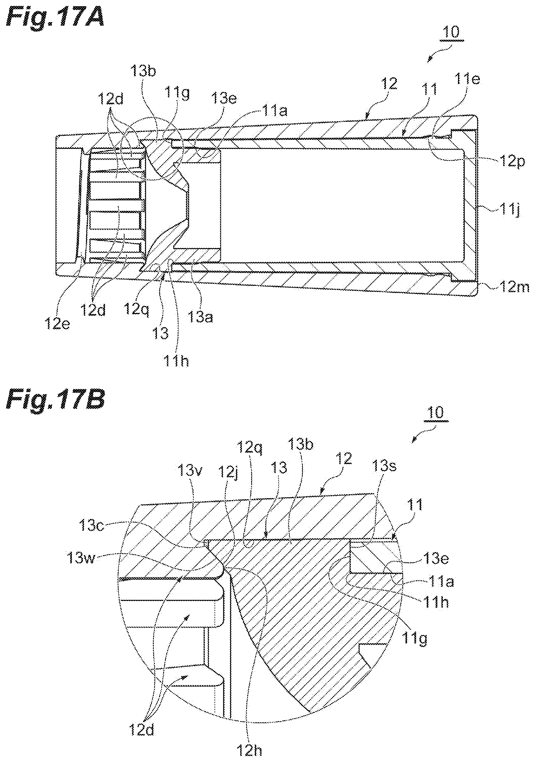
D00018

D00019

D00020

D00021
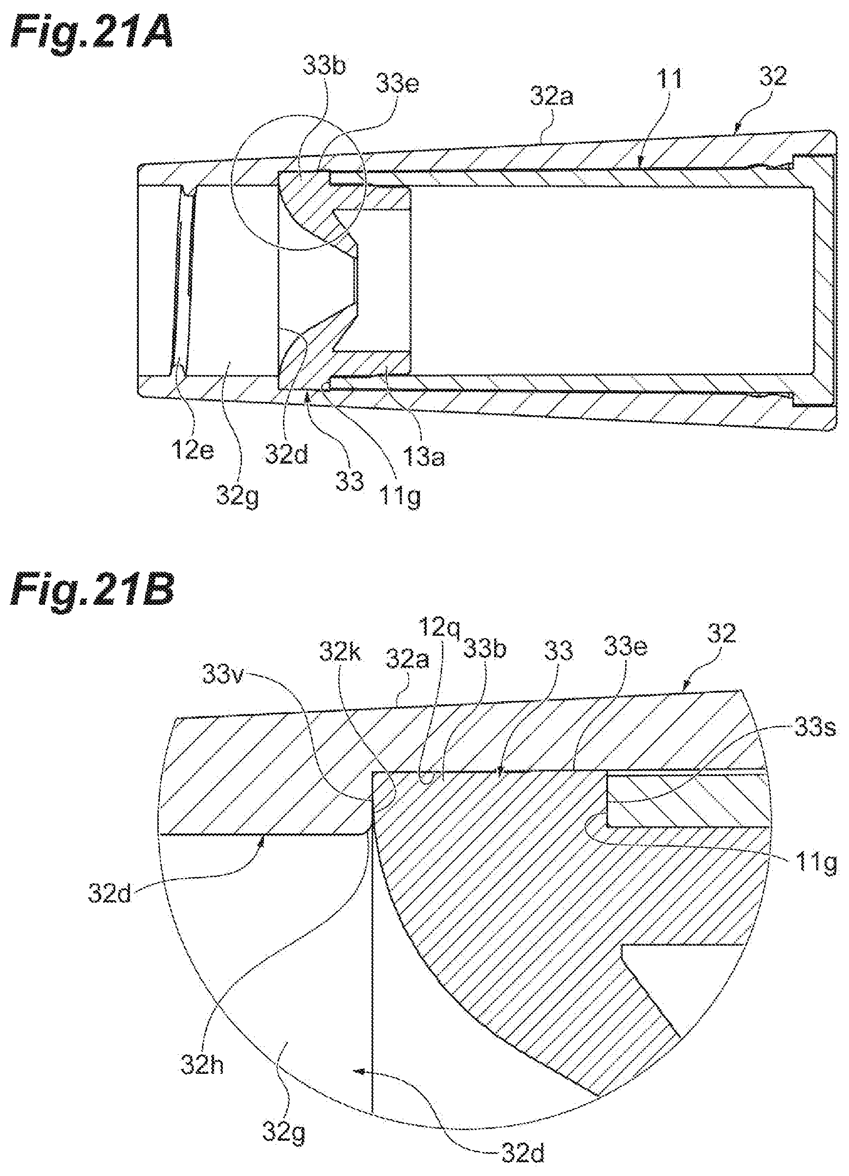
XML
uspto.report is an independent third-party trademark research tool that is not affiliated, endorsed, or sponsored by the United States Patent and Trademark Office (USPTO) or any other governmental organization. The information provided by uspto.report is based on publicly available data at the time of writing and is intended for informational purposes only.
While we strive to provide accurate and up-to-date information, we do not guarantee the accuracy, completeness, reliability, or suitability of the information displayed on this site. The use of this site is at your own risk. Any reliance you place on such information is therefore strictly at your own risk.
All official trademark data, including owner information, should be verified by visiting the official USPTO website at www.uspto.gov. This site is not intended to replace professional legal advice and should not be used as a substitute for consulting with a legal professional who is knowledgeable about trademark law.