Air filter arrangement; assembly; and, methods
Reichter , et al. December 15, 2
U.S. patent number 10,864,475 [Application Number 16/119,121] was granted by the patent office on 2020-12-15 for air filter arrangement; assembly; and, methods. This patent grant is currently assigned to Donaldson Company, Inc.. The grantee listed for this patent is Donaldson Company, Inc.. Invention is credited to Wayne R. W. Bishop, Bruce Crenshaw, Jordan S. Flagstad, Vladimir Kladnitsky, Bradley A. Kuempel, Thomas J. Lundgren, Donald Raymond Mork, Benny K. Nelson, Richard J. Osendorf, Gregory L. Reichter, Kevin Schrage, Darrel Wegner.
View All Diagrams
| United States Patent | 10,864,475 |
| Reichter , et al. | December 15, 2020 |
Air filter arrangement; assembly; and, methods
Abstract
An air cleaner arrangement is shown. The air cleaner arrangement includes a serviceable filter cartridge. A preferred filter cartridge positionable within an air cleaner arrangement, is depicted.
| Inventors: | Reichter; Gregory L. (Bloomington, MN), Bishop; Wayne R. W. (St. Louis Park, MN), Nelson; Benny K. (Bloomington, MN), Wegner; Darrel (Burnsville, MN), Crenshaw; Bruce (Frankfurt, IN), Kladnitsky; Vladimir (Eagan, MN), Mork; Donald Raymond (Lime Springs, IA), Schrage; Kevin (Spring Valley, MN), Osendorf; Richard J. (West St. Paul, MN), Kuempel; Bradley A. (Eden Prairie, MN), Lundgren; Thomas J. (Bloomington, MN), Flagstad; Jordan S. (East Bethel, MN) | ||||||||||
|---|---|---|---|---|---|---|---|---|---|---|---|
| Applicant: |
|
||||||||||
| Assignee: | Donaldson Company, Inc.
(Minneapolis, MN) |
||||||||||
| Family ID: | 1000005242524 | ||||||||||
| Appl. No.: | 16/119,121 | ||||||||||
| Filed: | August 31, 2018 |
Prior Publication Data
| Document Identifier | Publication Date | |
|---|---|---|
| US 20180369736 A1 | Dec 27, 2018 | |
Related U.S. Patent Documents
| Application Number | Filing Date | Patent Number | Issue Date | ||
|---|---|---|---|---|---|
| 14935860 | Nov 9, 2015 | 10065145 | |||
| 14165042 | Nov 10, 2015 | 9180399 | |||
| 13952987 | Jan 28, 2014 | 8636820 | |||
| 11795178 | Jul 30, 2013 | 8496723 | |||
| PCT/US2006/001021 | Jan 12, 2006 | ||||
| 60644094 | Jan 13, 2005 | ||||
| Current U.S. Class: | 1/1 |
| Current CPC Class: | B01D 46/0005 (20130101); B01D 46/526 (20130101); B01D 2271/022 (20130101) |
| Current International Class: | B01D 46/52 (20060101); B01D 46/00 (20060101) |
References Cited [Referenced By]
U.S. Patent Documents
| 2093877 | September 1937 | Pentz |
| 2270969 | January 1942 | Robinson |
| 2306325 | December 1942 | Allam |
| 2915325 | December 1959 | Buker |
| 2955028 | October 1960 | Bevans |
| 3025963 | March 1962 | Bauer |
| 3224592 | December 1965 | Burns et al. |
| 3494113 | February 1970 | Kinney |
| 3598738 | August 1971 | Biswell et al. |
| 3645402 | February 1972 | Alexander et al. |
| 3687849 | August 1972 | Abbott |
| 3749247 | July 1973 | Rohde |
| 4014794 | March 1977 | Lewis |
| 4061572 | December 1977 | Cohen et al. |
| 4066559 | January 1978 | Rohde |
| 4075097 | February 1978 | Paul |
| 4075098 | February 1978 | Paul et al. |
| 4080185 | March 1978 | Richter et al. |
| 4144166 | March 1979 | Dejovine |
| 4144169 | March 1979 | Grueschow |
| 4324213 | April 1982 | Kasting et al. |
| 4364751 | December 1982 | Copley |
| 4402912 | September 1983 | Krueger et al. |
| 4410427 | October 1983 | Wydeven |
| 4452616 | June 1984 | Gillingham et al. |
| 4589983 | May 1986 | Wydevan |
| 4600420 | July 1986 | Wydeven et al. |
| 4738776 | April 1988 | Brown |
| 4755289 | July 1988 | Villani |
| 4782891 | November 1988 | Cheadle et al. |
| 4826517 | May 1989 | Norman |
| 4861359 | August 1989 | Tettman |
| 4925561 | May 1990 | Ishii et al. |
| 4979969 | December 1990 | Sturmon |
| 5024268 | June 1991 | Cheadle et al. |
| 5050549 | September 1991 | Herding |
| 5064799 | November 1991 | Cheadle et al. |
| 5094745 | March 1992 | Monte et al. |
| 5120334 | June 1992 | Cooper |
| 5222488 | February 1993 | Forsgren et al. |
| 5213596 | May 1993 | Kume et al. |
| 5223011 | June 1993 | Hanni |
| 5225081 | July 1993 | Brownawell et al. |
| 5258118 | November 1993 | Reynolds |
| 5342511 | August 1994 | Brownawell |
| 5382355 | January 1995 | Arlozynski |
| 5391212 | February 1995 | Ernst et al. |
| 5435346 | July 1995 | Tregidgo et al. |
| 5459074 | October 1995 | Muoni |
| 5472379 | December 1995 | Andress et al. |
| 5472463 | December 1995 | Herman et al. |
| 5494497 | February 1996 | Lee |
| 5498332 | March 1996 | Handtmann |
| 5512074 | April 1996 | Hanni et al. |
| 5531848 | July 1996 | Brinda |
| 5541330 | July 1996 | Wear et al. |
| 5556542 | September 1996 | Berman et al. |
| 5562825 | October 1996 | Yamada et al. |
| 5575826 | November 1996 | Gillingham et al. |
| 5591330 | January 1997 | Lefebvre |
| 5605554 | February 1997 | Kennedy |
| 5643541 | July 1997 | Peddicord et al. |
| 5662799 | September 1997 | Hudgens et al. |
| 5718258 | February 1998 | Lefebvre et al. |
| 5759217 | February 1998 | Joy et al. |
| 5738785 | April 1998 | Brown et al. |
| 5753116 | May 1998 | Baumann et al. |
| 5772873 | June 1998 | Hudgens et al. |
| 5772883 | June 1998 | Rothman et al. |
| 5795361 | August 1998 | Lanier, Jr. et al. |
| 5803024 | September 1998 | Brown |
| 5820646 | October 1998 | Gillingham et al. |
| 5853439 | December 1998 | Gieseke et al. |
| 5891402 | April 1999 | Sassa et al. |
| 5902364 | May 1999 | Tokar et al. |
| 5948248 | September 1999 | Brown |
| 6045692 | April 2000 | Bilski et al. |
| D425189 | May 2000 | Gillingham et al. |
| 6086763 | July 2000 | Baumaun |
| 6096208 | August 2000 | Connelly et al. |
| 6098575 | August 2000 | Mulshine et al. |
| 6129852 | October 2000 | Elliot et al. |
| 6149700 | November 2000 | Morgan et al. |
| 6165519 | December 2000 | Lehrer et al. |
| 6171355 | January 2001 | Gieseke et al. |
| D437402 | February 2001 | Gieseke et al. |
| 6190432 | February 2001 | Gieseke et al. |
| 6196019 | March 2001 | Higo et al. |
| 6231630 | May 2001 | Ernst et al. |
| 6235194 | May 2001 | Jousset |
| 6235195 | May 2001 | Tokar |
| 6238554 | May 2001 | Martin, Jr. et al. |
| 6238561 | May 2001 | Liu et al. |
| D444219 | June 2001 | Gieseke et al. |
| 6261334 | July 2001 | Morgan et al. |
| 6264833 | July 2001 | Reamsnyder et al. |
| RE37369 | September 2001 | Hudgens et al. |
| 6306193 | October 2001 | Morgan et al. |
| D450828 | November 2001 | Tokar |
| 6348084 | February 2002 | Gieseke et al. |
| 6348085 | February 2002 | Tokar et al. |
| 6350291 | February 2002 | Gieske et al. |
| D455826 | April 2002 | Gillingham et al. |
| 6379564 | April 2002 | Rohrbach et al. |
| 6391076 | May 2002 | Jaroszczyk et al. |
| 6398832 | June 2002 | Morgan et al. |
| 6416561 | July 2002 | Kallsen et al. |
| 6375700 | August 2002 | Jaroszczyk et al. |
| 6475379 | November 2002 | Jousset et al. |
| 6478958 | November 2002 | Beard et al. |
| 6482247 | November 2002 | Jaroszczyk et al. |
| 6511599 | January 2003 | Jaroszczyk et al. |
| 6517598 | February 2003 | Anderson et al. |
| 6537453 | March 2003 | Beard et al. |
| D473637 | April 2003 | Golden |
| 6547857 | April 2003 | Gieseke et al. |
| 6554139 | April 2003 | Maxwell et al. |
| 6596165 | July 2003 | Koivula |
| 6610126 | August 2003 | Xu et al. |
| 6623636 | September 2003 | Rohrbach et al. |
| 6641637 | November 2003 | Kallsen et al. |
| 6673136 | January 2004 | Gillingham et al. |
| 6676721 | January 2004 | Gillingham et al. |
| 6709588 | March 2004 | Pavlin et al. |
| 6743317 | June 2004 | Wydeven |
| 6746518 | June 2004 | Gieseke et al. |
| 6787033 | September 2004 | Beard et al. |
| 6827750 | December 2004 | Drozd et al. |
| 6835304 | December 2004 | Jousset et al. |
| 6843916 | January 2005 | Burington et al. |
| 6860241 | March 2005 | Martin et al. |
| 6893571 | May 2005 | Harenbrock et al. |
| 6902598 | June 2005 | Gunderson et al. |
| 6919023 | July 2005 | Merritt et al. |
| 6953124 | October 2005 | Winter et al. |
| 6966940 | November 2005 | Krisko et al. |
| 6969461 | November 2005 | Beard et al. |
| 6984319 | January 2006 | Merritt et al. |
| 7001450 | February 2006 | Gieseke et al. |
| 7018531 | March 2006 | Eilers et al. |
| 7090711 | August 2006 | Gillingham et al. |
| 7153422 | December 2006 | Herman et al. |
| 7156991 | January 2007 | Herman et al. |
| 7160451 | January 2007 | Hacker et al. |
| 7182863 | February 2007 | Eilers et al. |
| 7182864 | February 2007 | Brown et al. |
| 7211124 | May 2007 | Gieseke et al. |
| 7247183 | July 2007 | Connor et al. |
| 7258719 | August 2007 | Miller et al. |
| 7282075 | October 2007 | Sporre et al. |
| 7338544 | March 2008 | Sporre et al. |
| 7351270 | April 2008 | Engelland et al. |
| 7396371 | July 2008 | Nepsund et al. |
| 7396375 | July 2008 | Nepsund et al. |
| 7494017 | February 2009 | Miller |
| 7540895 | June 2009 | Furseth et al. |
| D600790 | September 2009 | Nelson et al. |
| 7625419 | December 2009 | Nelson et al. |
| 7655074 | February 2010 | Nepsund et al. |
| 7682416 | March 2010 | Engelland et al. |
| 7799108 | September 2010 | Connor et al. |
| 7967886 | June 2011 | Schrage et al. |
| 8016903 | September 2011 | Nelson et al. |
| 8034145 | October 2011 | Boehrs et al. |
| 8062399 | November 2011 | Nelson et al. |
| 8241383 | August 2012 | Schrage et al. |
| 8277532 | October 2012 | Reichter et al. |
| 8292983 | October 2012 | Reichter et al. |
| 8328897 | December 2012 | Nelson et al. |
| 8357219 | January 2013 | Boehrs et al. |
| 8480779 | July 2013 | Boehrs et al. |
| 8496723 | July 2013 | Reichter et al. |
| 8636820 | January 2014 | Reichter et al. |
| 8709119 | April 2014 | Reichter et al. |
| 8840699 | September 2014 | Boehrs et al. |
| 8906128 | December 2014 | Reichter et al. |
| 9120047 | September 2015 | Boehrs et al. |
| 9180399 | November 2015 | Reichter et al. |
| 9320997 | April 2016 | Campbell et al. |
| 9399972 | July 2016 | Boehrs et al. |
| 9527023 | December 2016 | Reichter et al. |
| 9795911 | October 2017 | Reichter et al. |
| 9937455 | April 2018 | Boehrs et al. |
| 10065145 | September 2018 | Reichter |
| 2001/0032545 | October 2001 | Goto et al. |
| 2002/0060178 | May 2002 | Tsabari |
| 2002/0070181 | June 2002 | Deanda et al. |
| 2002/0073850 | June 2002 | Tokar et al. |
| 2002/0096247 | July 2002 | Wydeven |
| 2002/0170280 | November 2002 | Soh |
| 2002/0185454 | December 2002 | Beard et al. |
| 2002/0195384 | December 2002 | Rohrbach et al. |
| 2003/0121845 | July 2003 | Wagner et al. |
| 2003/0154863 | August 2003 | Tokar et al. |
| 2003/0218150 | November 2003 | Blakemore et al. |
| 2004/0035097 | February 2004 | Schlensker et al. |
| 2004/0060861 | April 2004 | Winter et al. |
| 2004/0091654 | May 2004 | Kelly et al. |
| 2004/0140255 | July 2004 | Merritt et al. |
| 2004/0173097 | September 2004 | Engelland et al. |
| 2004/0187689 | September 2004 | Sporre et al. |
| 2004/0221555 | November 2004 | Engelland et al. |
| 2004/0226443 | November 2004 | Gillingham et al. |
| 2005/0019236 | January 2005 | Martin et al. |
| 2005/0166561 | August 2005 | Schrage et al. |
| 2005/0194312 | September 2005 | Niemeyer et al. |
| 2005/0224061 | October 2005 | Ulrich et al. |
| 2005/0252848 | November 2005 | Miller |
| 2006/0113233 | June 2006 | Merritt et al. |
| 2006/0180537 | August 2006 | Loftis et al. |
| 2007/0261374 | November 2007 | Nelson et al. |
| 2008/0022641 | January 2008 | Engelland et al. |
| 2008/0110142 | May 2008 | Nelson et al. |
| 2008/0250763 | October 2008 | Widerski et al. |
| 2008/0250766 | October 2008 | Schrage et al. |
| 2008/0276582 | November 2008 | Boehrs et al. |
| 2008/0307759 | December 2008 | Reichter et al. |
| 2009/0057213 | March 2009 | Schiavon et al. |
| 2009/0064646 | March 2009 | Reichter et al. |
| 2009/0151311 | June 2009 | Reichter et al. |
| 2010/0043366 | February 2010 | Boehrs et al. |
| 2010/0170209 | April 2010 | Nelson et al. |
| 2296402 | Nov 1998 | CN | |||
| 88 08 632 | Sep 1988 | DE | |||
| 296 13 098 | Oct 1996 | DE | |||
| 1 233 173 | Aug 2002 | EP | |||
| 970826 | Sep 1964 | GB | |||
| 970826 | Sep 1964 | GB | |||
| 2 082 932 | Mar 1982 | GB | |||
| 60-112320 | Jul 1985 | JP | |||
| 1-171615 | Apr 1989 | JP | |||
| 1-163408 | Nov 1989 | JP | |||
| 2-25009 | Feb 1990 | JP | |||
| WO 97/40908 | Nov 1997 | WO | |||
| WO 98/12430 | Mar 1998 | WO | |||
| WO 99/00587 | Jul 1999 | WO | |||
| WO 01/97946 | Dec 2001 | WO | |||
| WO 02/092193 | Nov 2002 | WO | |||
| 2003/084641 | Oct 2003 | WO | |||
| WO 2003/095068 | Nov 2003 | WO | |||
| WO 2004/052504 | Jun 2004 | WO | |||
| WO 2004/054684 | Jul 2004 | WO | |||
| WO 2005/046841 | May 2005 | WO | |||
| WO 2005/058461 | Jun 2005 | WO | |||
| WO 2005/077487 | Aug 2005 | WO | |||
| WO 2005/079954 | Sep 2005 | WO | |||
| WO 2007/009039 | Jan 2007 | WO | |||
Other References
|
US. Appl. No. 60/579,754. cited by applicant . Pending Claims of U.S. Appl. No. 15/946,818 dated Aug. 31, 2018. cited by applicant . Pending claims corresponding to U.S. Appl. No. 15/788,937 dated Aug. 31, 2018. cited by applicant . Pending claims corresponding to U.S. Appl. No. 14/935,860 dated Aug. 31, 2018. cited by applicant . Pending claims corresponding to U.S. Appl. No. 15/211,099 dated Aug. 31, 2018. cited by applicant . Pending claims of U.S. Appl. No. 15/539,600 dated Aug. 31, 2018. cited by applicant . Pending claims of U.S. Appl. No. 15/137,089 dated Aug. 31, 2018. cited by applicant . Pending claims of U.S. Appl. No. 15/541,122 dated Aug. 31, 2018. cited by applicant. |
Primary Examiner: Clemente; Robert
Attorney, Agent or Firm: Merchant & Gould P.C.
Parent Case Text
This application is a continuing application of U.S. Ser. No. 14/935,860, filed Nov. 9, 2015. U.S. Ser. No. 14/935,860 is a continuation of U.S. Ser. No. 14/165,042, filed Jan. 27, 2014, which issued as U.S. Pat. No. 9,180,399 on Nov. 10, 2015. U.S. Ser. No. 14/165,042 was a continuation of U.S. Ser. No. 13/952,987, filed Jul. 29, 2013, which issued as U.S. Pat. No. 8,636,820. U.S. Ser. No. 13/952,987 was a continuation of U.S. Ser. No. 11/795,178, which issued as U.S. Pat. No. 8,496,723. U.S. Ser. No. 11/795,178, filed 12 Jul. 2007, was a National Stage Patent Application of PCT International Patent application number PCT/US2006/001021 filed on 12 Jan. 2006 and claiming priority from 60/644,094, filed Jan. 13, 2005. The complete disclosures of U.S. Ser. Nos. 14/935,860; 14/165,042; 13/952,987; 11/795,178; PCT/US2006/001021; and, U.S. Ser. No. 60/644,094 are incorporated herein by reference. A claim of the priority to each of U.S. Ser. No. 14/935,860; U.S. Ser. No. 14/165,042; U.S. Ser. No. 13/952,987; U.S. Ser. No. 11/795,178; PCT/US2006/001021; and, U.S. Ser. No. 60/644,094 is made to the extent appropriate.
Claims
What is claimed is:
1. An air filter cartridge comprising: (a) a filter media pack having first and second, opposite, flow faces, and having an axial direction extending from the first flow face to the second flow face; (i) the filter media pack comprising sets of axially extending flow channels, wherein a set of axially extending flow channels is located between axially extending sheets of media, and at least one of the axially extending sheets of media comprises fold lines forming the set of axially extending flow channels; (ii) the first and second, opposite, flow faces being generally planar and parallel to one another; and (iii) the media pack having a shape with: a first cross-dimension perpendicular to a direction between the first and second, opposite, flow faces; and, a second cross-dimension, perpendicular to a direction between the first and second, opposite, flow faces and also perpendicular to the first cross-dimension; and, (b) a housing seal arrangement comprising a perimeter seal extending around the media pack; (i) the housing seal arrangement including a pinch seal; (ii) the pinch seal having a first, end, pinch seal surface in complete extension around the media pack; (A) the first, end, pinch seal surface being an end surface facing generally in the same direction as one of the first flow face and second flow face; and, (B) the housing seal arrangement being configured such that a portion of the first, end, pinch seal surface, in extension in a direction corresponding to the first cross-dimension, varies in distance from the second flow face, in at least selected locations.
2. An air filter cartridge according to claim 1 wherein: (a) the first, end, pinch seal surface is positioned spaced from each of the first and second, opposite, flow faces; and, (b) the first, end, pinch seal surface includes opposite long side sections extending in the direction at the first cross-dimension; (i) the opposite long sections being parallel to one another and extending at an angle Y of greater than zero, relative to the outlet flow face.
3. An air filter cartridge according to claim 2 wherein: (a) the angle Y is not greater than 45.degree..
4. An air filter cartridge according to claim 2 wherein: (a) the angle Y is at least 5.degree..
5. An air filter cartridge according to claim 2 wherein: (a) the first, end, seal surface includes opposite short side sections extending between the opposite long sections.
6. An air filter cartridge according to claim 5 wherein: (a) each of the opposite short side sections extends in a direction parallel to the outlet flow face, in a direction of extension between the opposite long sections.
7. An air filter cartridge according to claim 6 wherein: (a) the filter media pack has rectangular cross-sectional shape.
8. An air filter cartridge according to claim 7 wherein: (a) the filter media pack comprises a stack of alternating strips of fluted media and facing media.
9. An air filter cartridge according to claim 1 wherein: (a) the filter media pack has rectangular cross-sectional shape.
10. An air filter cartridge according to claim 9 wherein: (a) the filter media pack comprises a stack of alternating strips of fluted media and facing media.
11. An air filter cartridge according to claim 1 wherein: (a) the housing seal arrangement comprises a pinch seal having a pinch seal flange and a pinch seal base; (i) the pinch seal flange and pinch seal base defining a receiving trough between a portion of the pinch seal base and the media pack.
12. An air filter cartridge according to claim 1 wherein: (a) at least 10% of a volume of the media pack is positioned on each side of the pinch seal arrangement.
13. An air filter cartridge according to claim 1 wherein: (a) at least 15% of a volume of the media pack is positioned on each side of the pinch seal arrangement.
14. An air filter cartridge according to claim 1 wherein: (a) a distance between the inlet and outlet flow faces is greater than the second cross-dimension.
15. An air filter cartridge according to claim 1 wherein: (a) the filter media pack includes a pair of opposite sides, each of which is embedded in a molded-in-place panel.
16. An air filter cartridge according to claim 15 wherein: (a) the filter media pack includes a second pair of opposite sides extending between the first pair of opposite sides and in the direction of the first cross-dimension; (i) each of the second pair of opposite sides being covered by a sheet of material.
17. An air filter cartridge according to claim 1 wherein: (a) the first cross-dimension being longer than the second cross-dimension.
18. An air filter cartridge according to claim 1 wherein: (a) the filter media pack wherein the axially extending sheet of media forming fold lines comprises fluted media.
19. An air filter cartridge according to claim 18 wherein: (a) the other axially extending sheet of media comprises facing media.
20. An air filter cartridge according to claim 19 wherein: (a) the facing media comprises non-corrugated media.
21. An air filter cartridge according to claim 19 wherein: (a) the facing media comprises corrugated media.
22. An air filter cartridge according to claim 1 wherein: (a) the axial flow channels comprise inlet flow channels open to flow at the first flow face and closed to flow at the second flow face, and outlet flow channels closed to flow at the first flow face and open to flow at the second flow face.
23. An air filter cartridge according to claim 19 wherein: (a) the filter media pack comprises alternating fluted media and facing media.
24. An air filter cartridge according to claim 23 wherein: (a) the alternating fluted media and facing media are secured to each other at one of the first flow face and the second flow faces.
25. An air filter cartridge according to claim 23 wherein: (a) the alternating fluted media and facing media comprises a stack of alternating strips of a fluted media sheet secured to a facing media sheet.
26. An air filter cartridge comprising: (a) a filter media pack having first and second flow faces, and having an axial direction extending from the first flow face to the second flow face; (ii) the media pack having a shape with: a first cross-dimension perpendicular to a direction between the first and second, opposite, flow faces; and, a second cross-dimension, perpendicular to a direction between the first and second, opposite, flow faces and also perpendicular to the first cross-dimension; and, (b) a housing seal arrangement comprising a perimeter seal extending around the media pack; (i) the housing seal arrangement including a pinch seal; (ii) the pinch seal having a first, end, pinch seal surface in complete extension around the media pack; (A) the first, end, pinch seal surface being an end surface facing generally in the same direction as one of the first flow face and second flow face; (B) the housing seal arrangement being configured such that a portion of the first, end, pinch seal surface, in extension in a direction corresponding to the first cross-dimension, varies in distance from the second flow face, in at least selected locations; and, (C) the pinch seal surface is positioned spaced from each of the first and second, opposite, flow faces.
27. An air filter cartridge according claim 26 wherein: (a) the media comprises alternating fluted media and facing media.
28. An air filter cartridge according to claim 26 wherein: (a) the first, end, pinch seal surface is positioned spaced from each of the first and second, opposite, flow faces; and, (b) the first, end, pinch seal surface includes opposite long side sections extending in the direction of the first cross-dimension along an angle Y, relative to a direction between the flow faces.
29. An air filter cartridge according to claim 26 wherein: (a) the housing seal arrangement comprises a pinch seal having a pinch seal flange and a pinch seal base; (i) the pinch seal flange and pinch seal base defining a receiving trough between a portion of the pinch seal base and the media pack.
30. An air filter cartridge according to claim 26 wherein: (a) the first cross-dimension being longer than the second cross-dimension.
Description
FIELD OF THE DISCLOSURE
The present disclosure relates to air cleaners. The disclosure particularly relates to air cleaners with media packs that use z-filter media comprising a fluted (typically corrugated) media sheet secured to a facing sheet, formed into a media pack. More specifically, the disclosure relates to such media packs provided in serviceable filter cartridge arrangements, typically for use in air cleaners. Air cleaner arrangements, methods of assembly and use, and systems of use are also described.
BACKGROUND
Air streams can carry contaminant material therein. In many instances, it is desired to filter some or all of the contaminant material from the air stream. For example, gas flow streams to engines (for example combustion air) for motorized vehicles or for power generation equipment, gas streams to gas turbine systems and air streams to various combustion furnaces, carry particulate contaminant therein that should be filtered. It is preferred for such systems, that selected contaminant material be removed from (or have its level reduced in) that gas. A variety of air filter arrangements have been developed for contaminant rejection. However, continued improvements are sought.
SUMMARY
According to a portion of the present disclosure, features useable in air cleaners and filter cartridges for the air cleaners provided. The features can be used together to provide a system, however some advantageous arrangements can be constructed to use only selected ones of the features. In addition, methods of construction and use are provided.
In one aspect of the present disclosure, a preferred media pack is provided, for use in or as air filter cartridges. The media pack comprises a stacked z-filter arrangement having opposite flow faces and opposite sides. At a pair of the opposite sides, ends of stacked strips are sealed, for example by end pieces such as molded-in-place end pieces, although alternatives are possible. In some examples the molded end pieces would comprise molded polyurethane. Also, a useable housing seal arrangement is provided. The housing seal arrangement can be provided as a molded-in-place seal arrangement.
Also, air cleaner arrangements, which use the filter cartridge as a service component, are described. In addition, shown and described are features of an air cleaner system and for example an environment of use. Also methods of assembly and use are shown and described.
BRIEF DESCRIPTION OF THE DRAWINGS
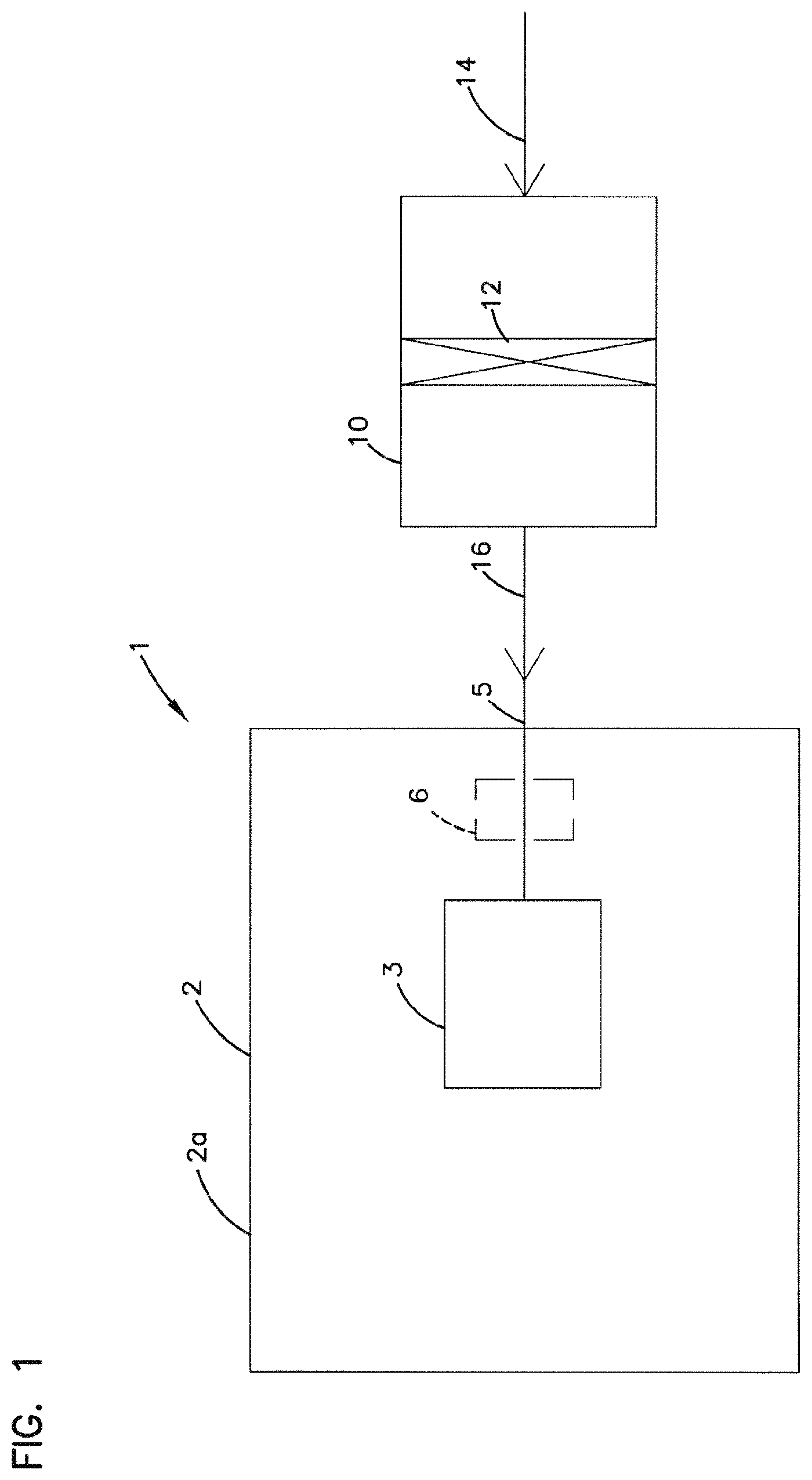
FIG. 1 is a schematic view of a system using an air cleaner assembly having a filter cartridge component according to the present disclosure.
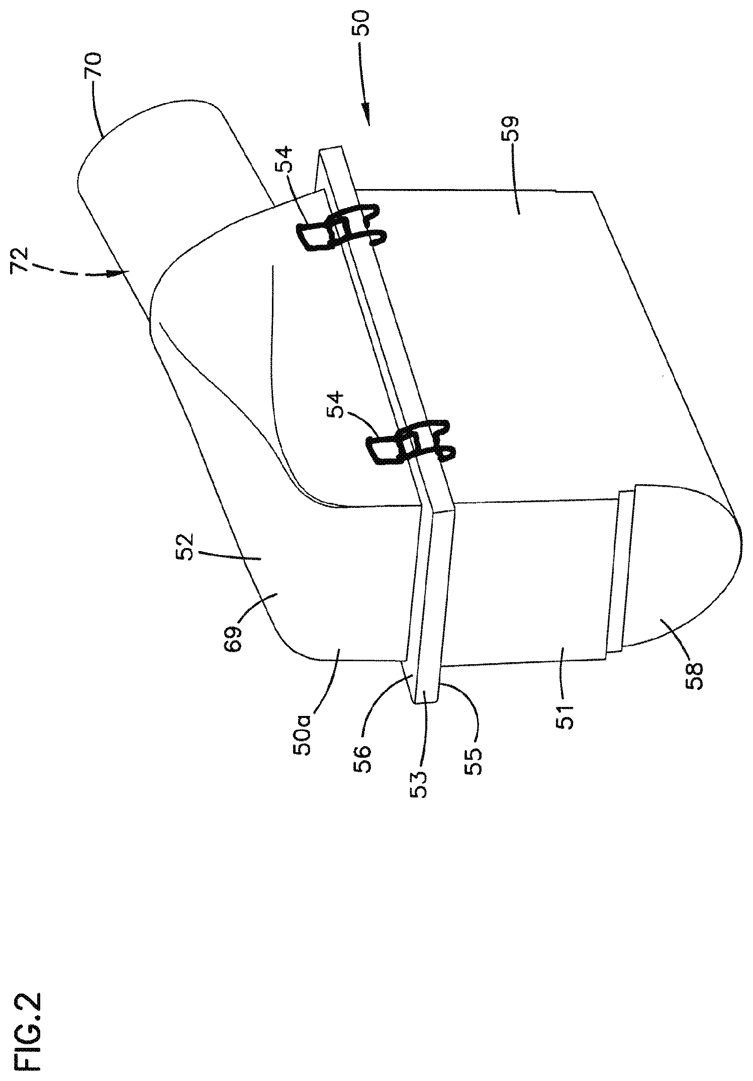
FIG. 2 is a schematic perspective view of an air cleaner assembly according to the present disclosure.
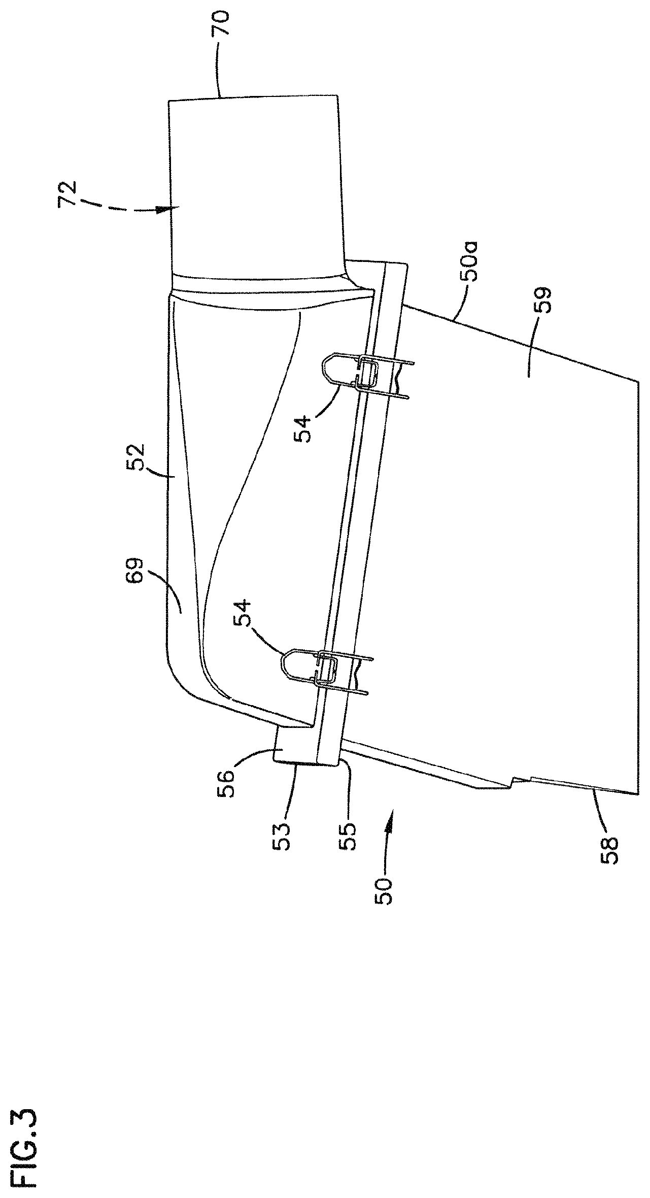
FIG. 3 is a side elevational view of the air cleaner assembly depicted in FIG. 2.
FIG. 4 is an inlet end view of the air cleaner assembly depicted in FIGS. 2 and 3.
FIG. 5 is a schematic view of the air cleaner assembly depicted in FIGS. 2-4, with a housing portion shown in see-through to allow viewing of a positioning of an internally received filter cartridge component.
FIG. 6 is a side elevational view of the arrangement depicted in FIG. 5.
FIG. 7 is a cross-sectional view of the arrangement depicted in FIG. 6.
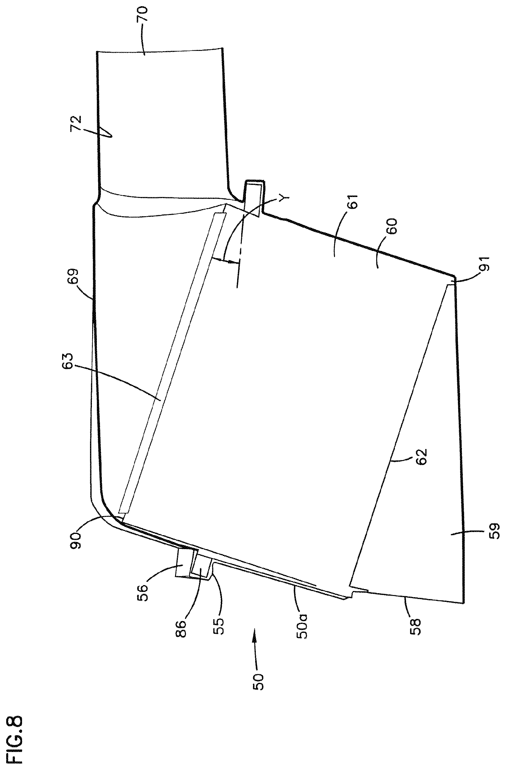
FIG. 8 is a schematic cross-sectional view analogous to FIG. 7, showing a possible housing seal location.
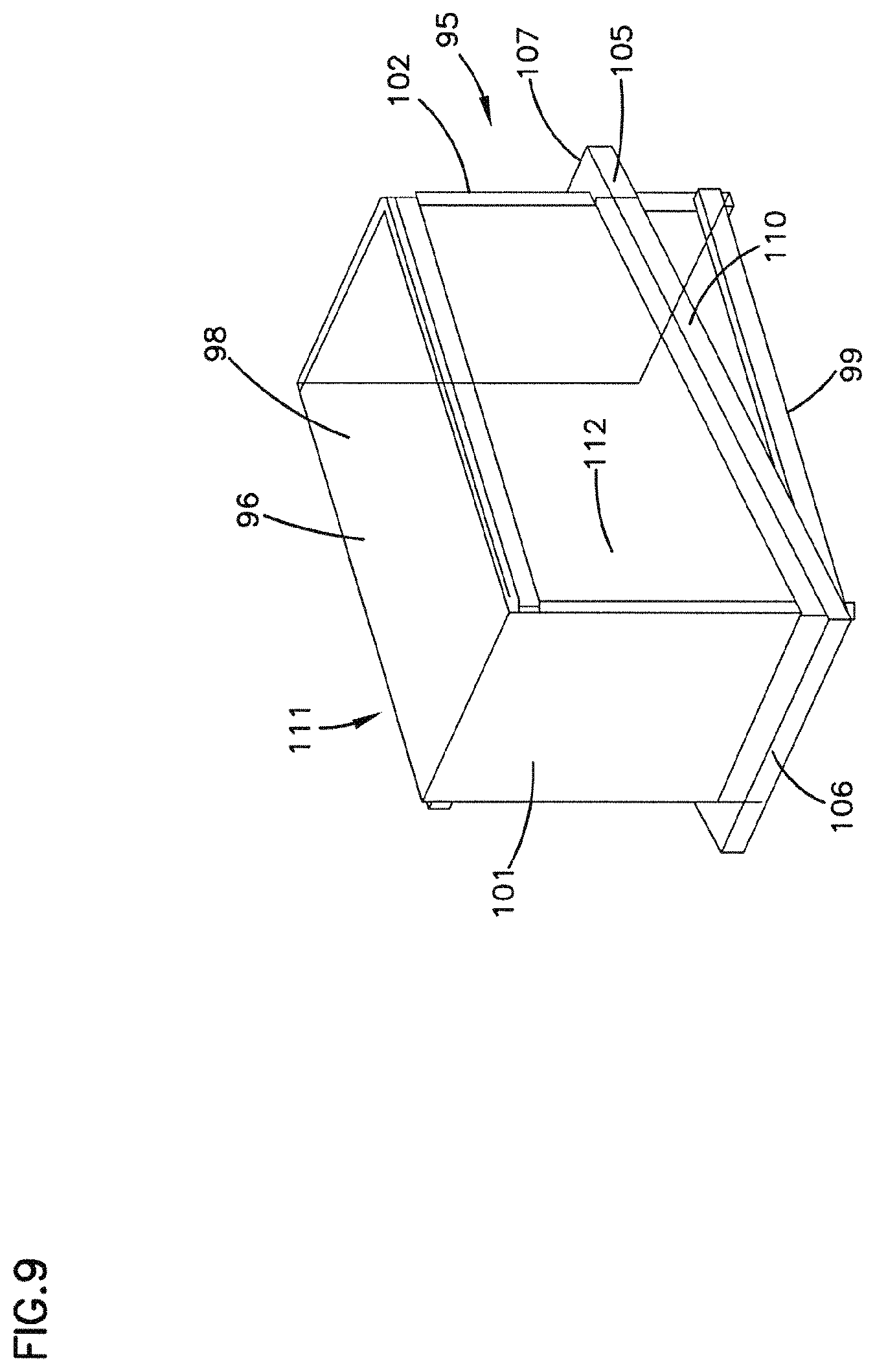
FIG. 9 is a schematic perspective view of a filter cartridge usable in the arrangement of FIG. 8.
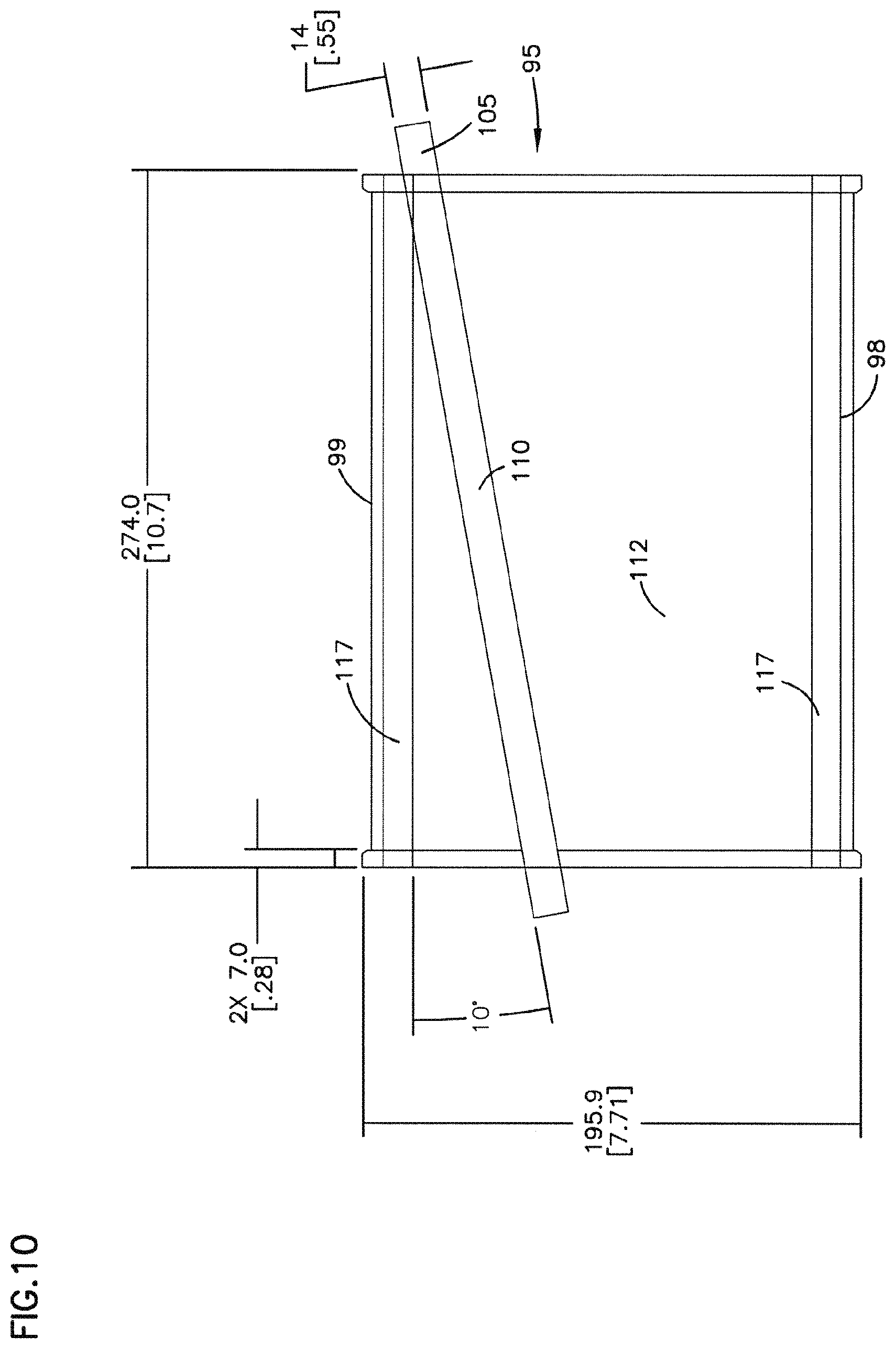
FIG. 10 is a side view of the arrangement shown in FIG. 9.
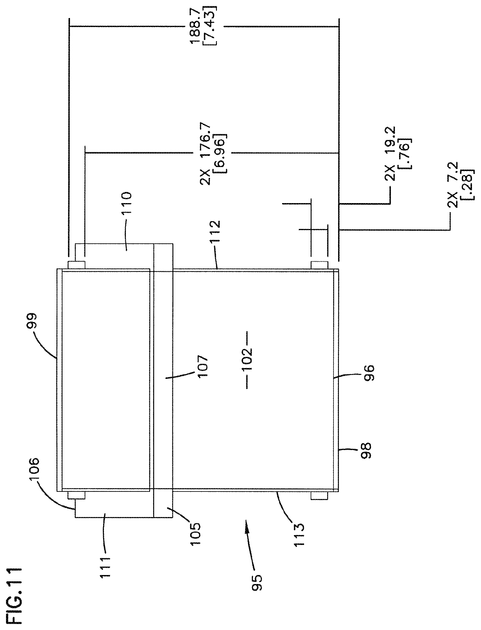
FIG. 11 is an end view of the arrangement shown in FIG. 9.
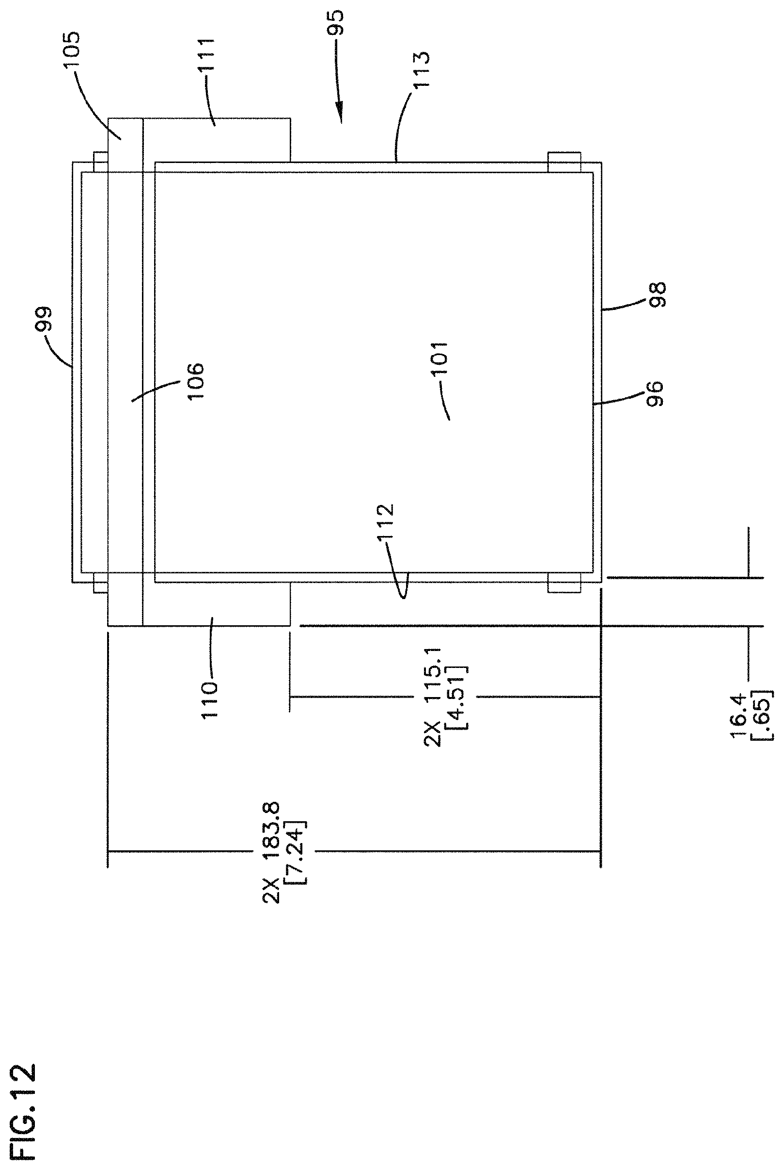
FIG. 12 is an opposite end view from FIG. 11.
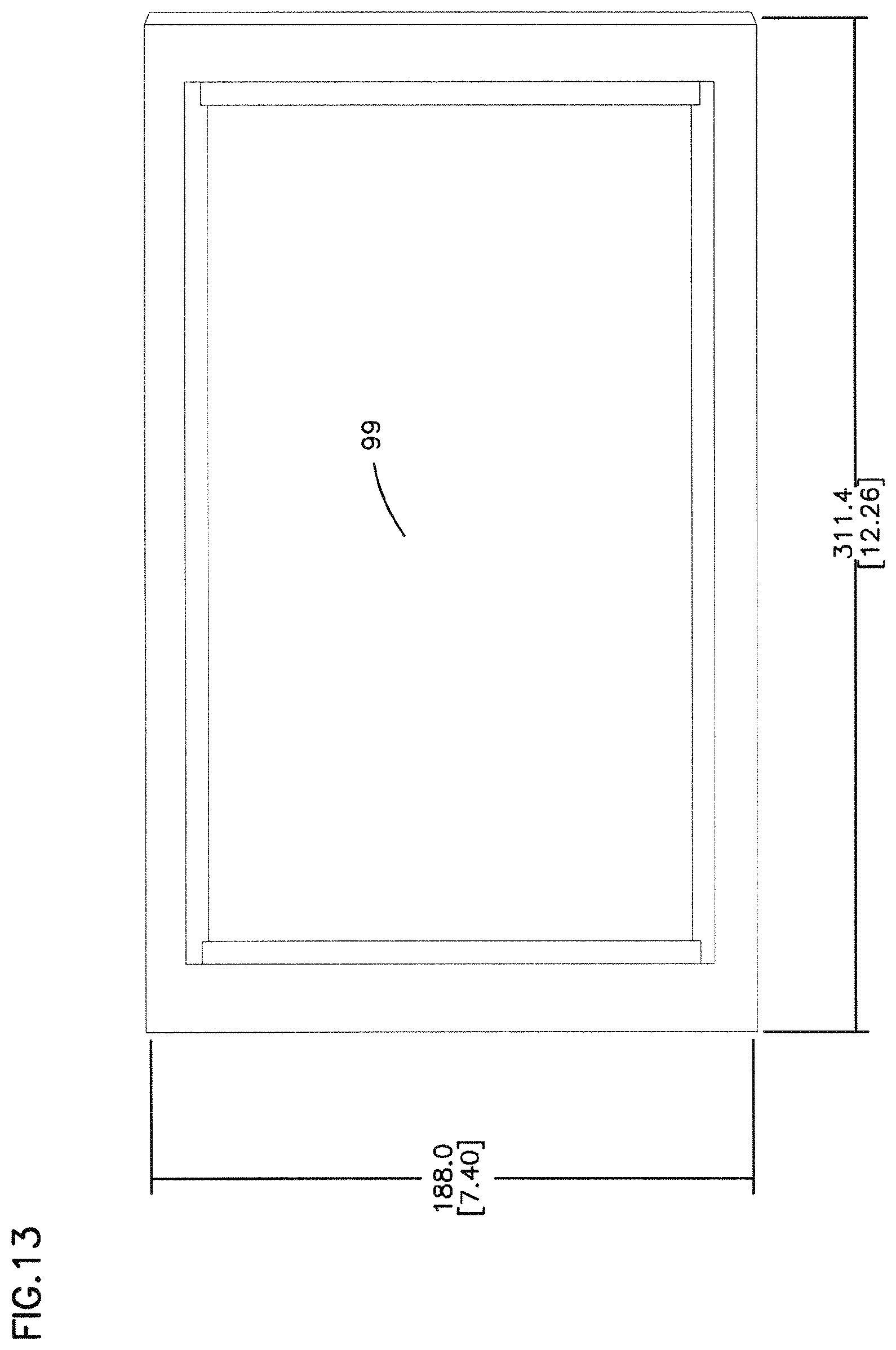
FIG. 13 is a view of an air flow face of the arrangement of FIG. 9.
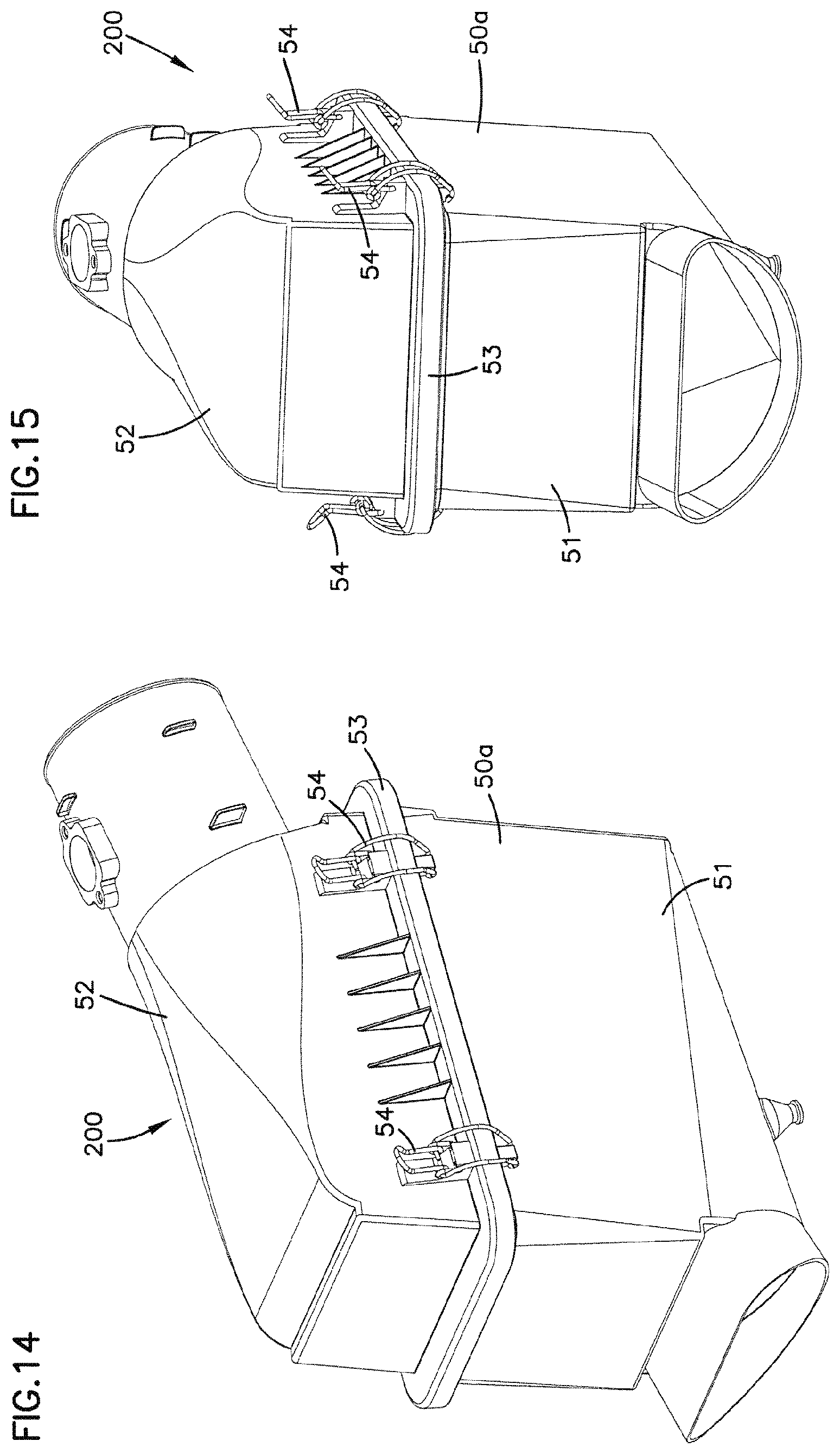
FIG. 14 is a side perspective view of a second air cleaner according to the present disclosure.
FIG. 15 is an end perspective view of the air cleaner of FIG. 14.
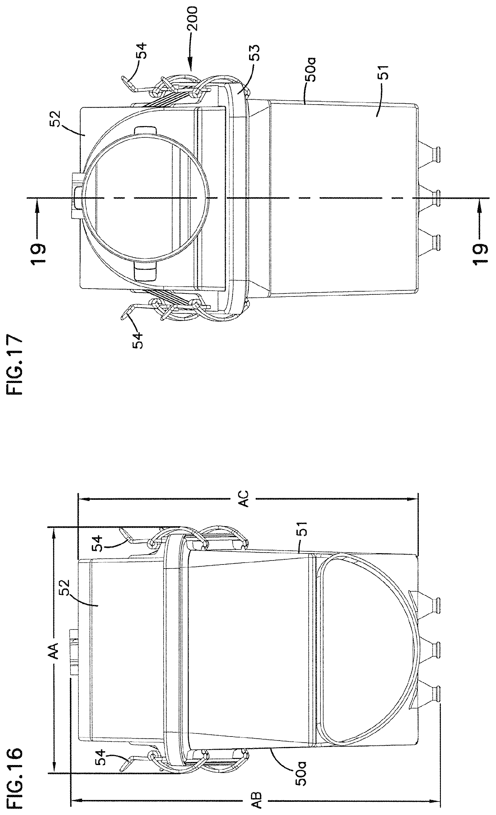
FIG. 16 is an inlet end elevational view of the air cleaner of FIGS. 14 and 15.
FIG. 17 is an outlet end elevational view of the air cleaner of FIGS. 14 and 15.
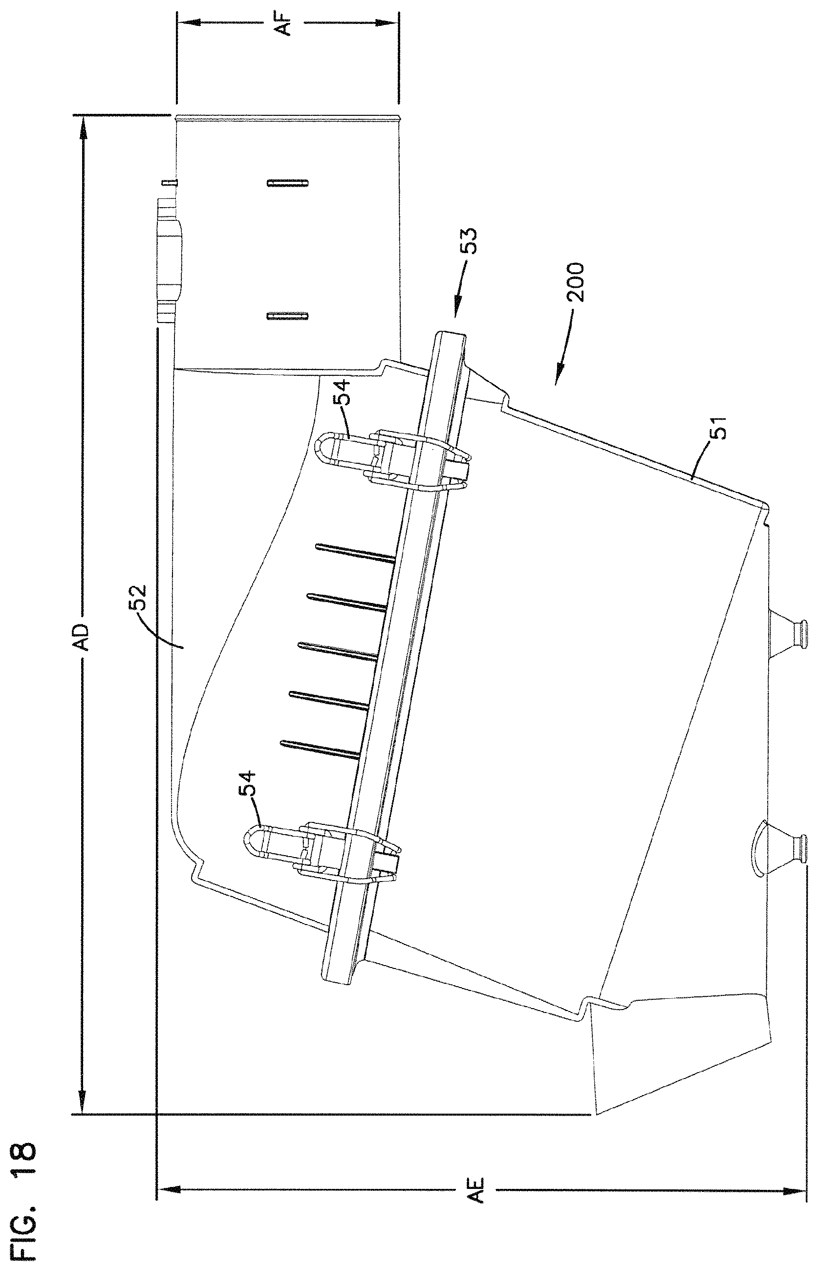
FIG. 18 is a side elevational view of the air cleaner of FIGS. 14-17.
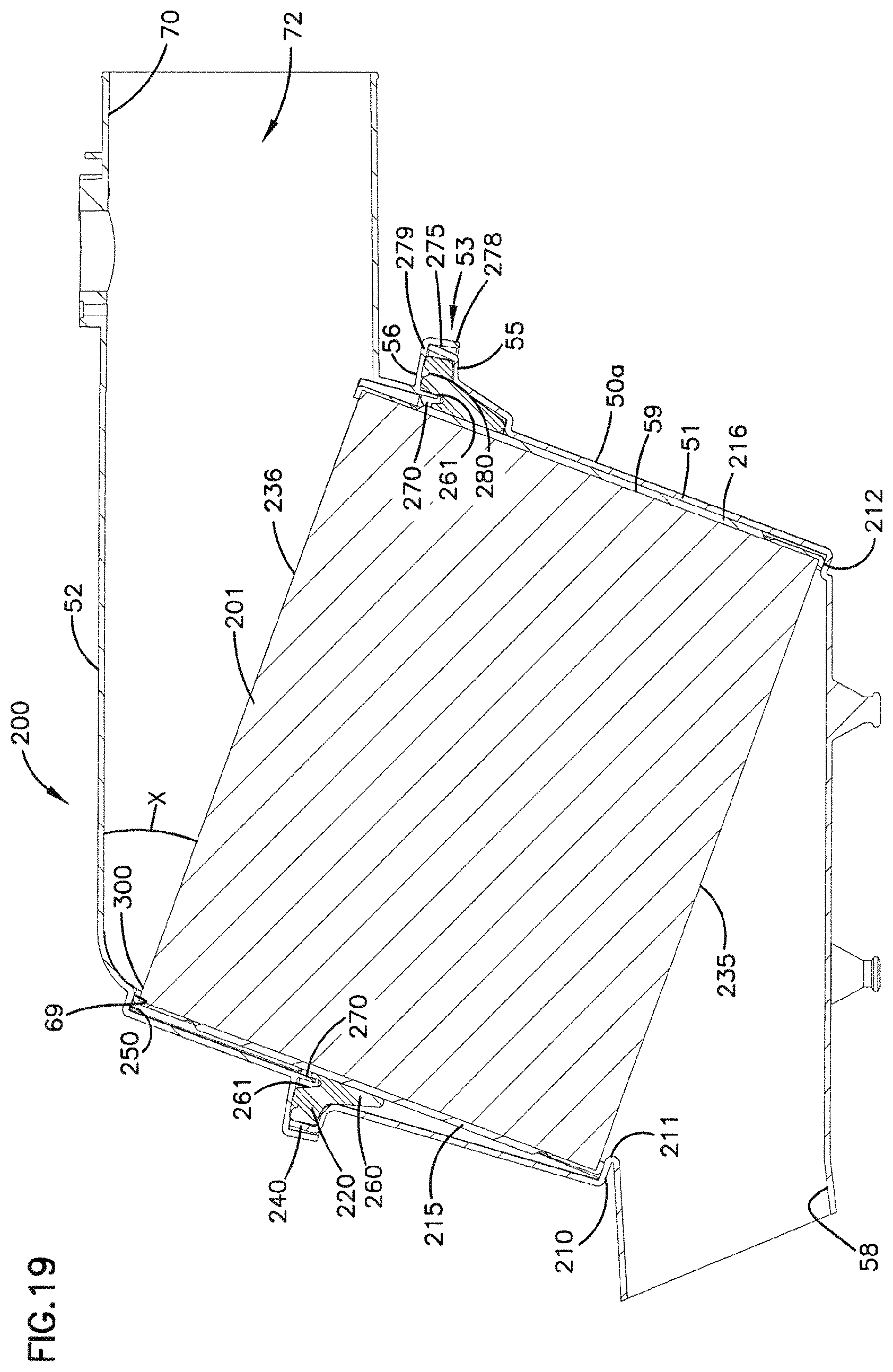
FIG. 19 is a cross-sectional view taken along line 19-19, FIG. 17.
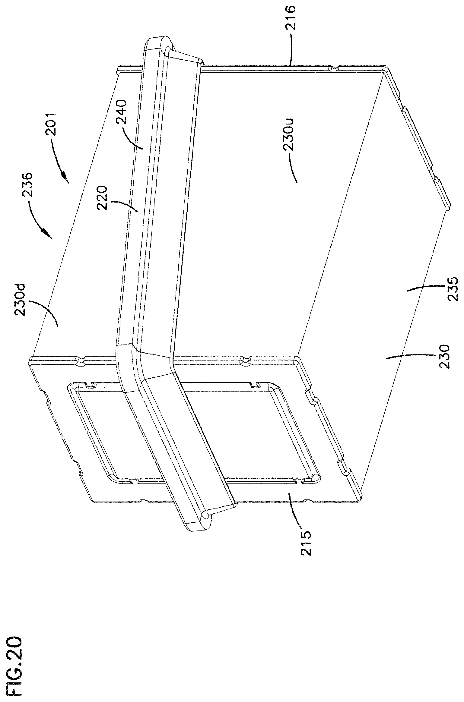
FIG. 20 is a schematic perspective view of a filter cartridge useable in the air cleaner of FIGS. 14-19.
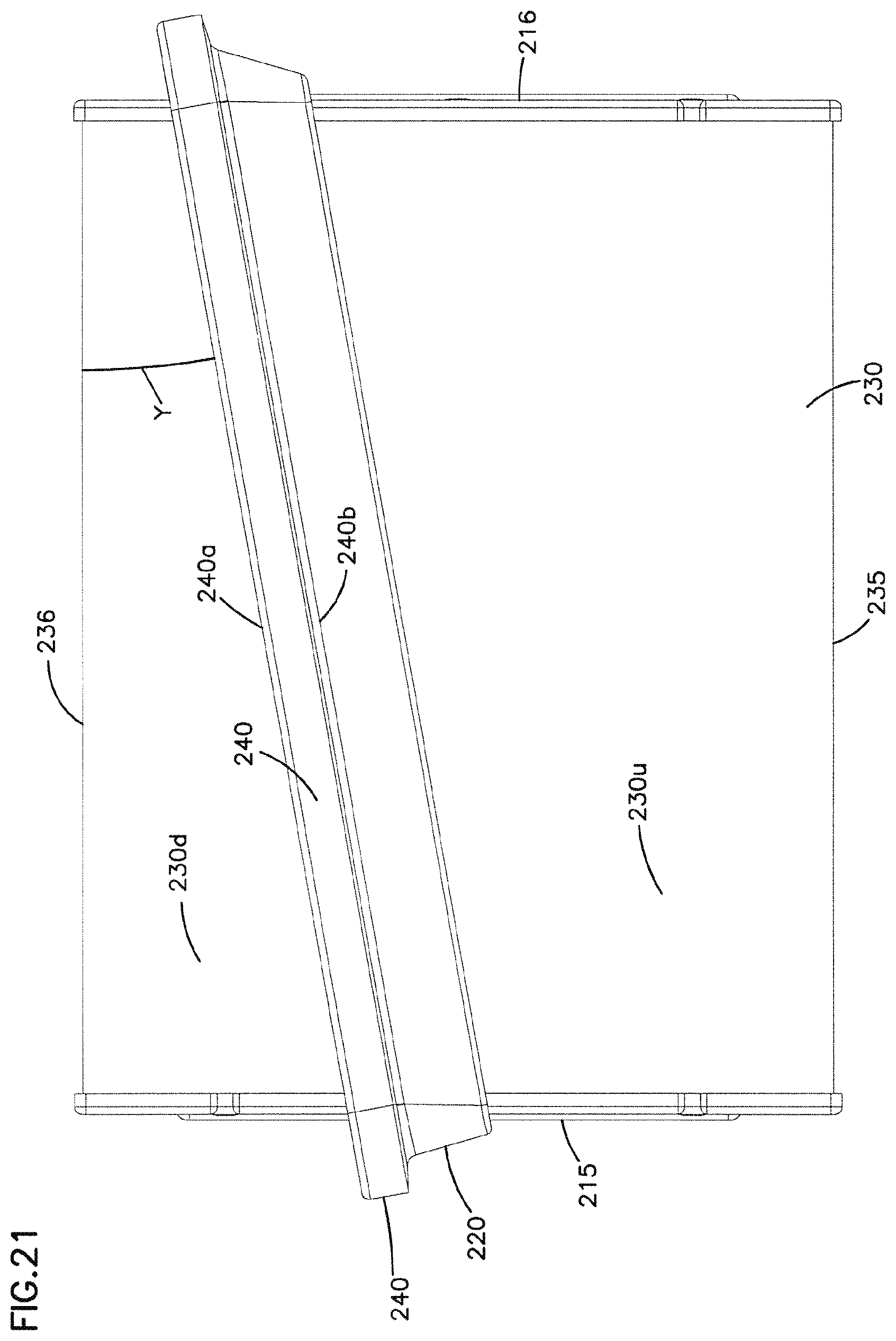
FIG. 21 is a side elevational view of the filter cartridge of FIG. 20.
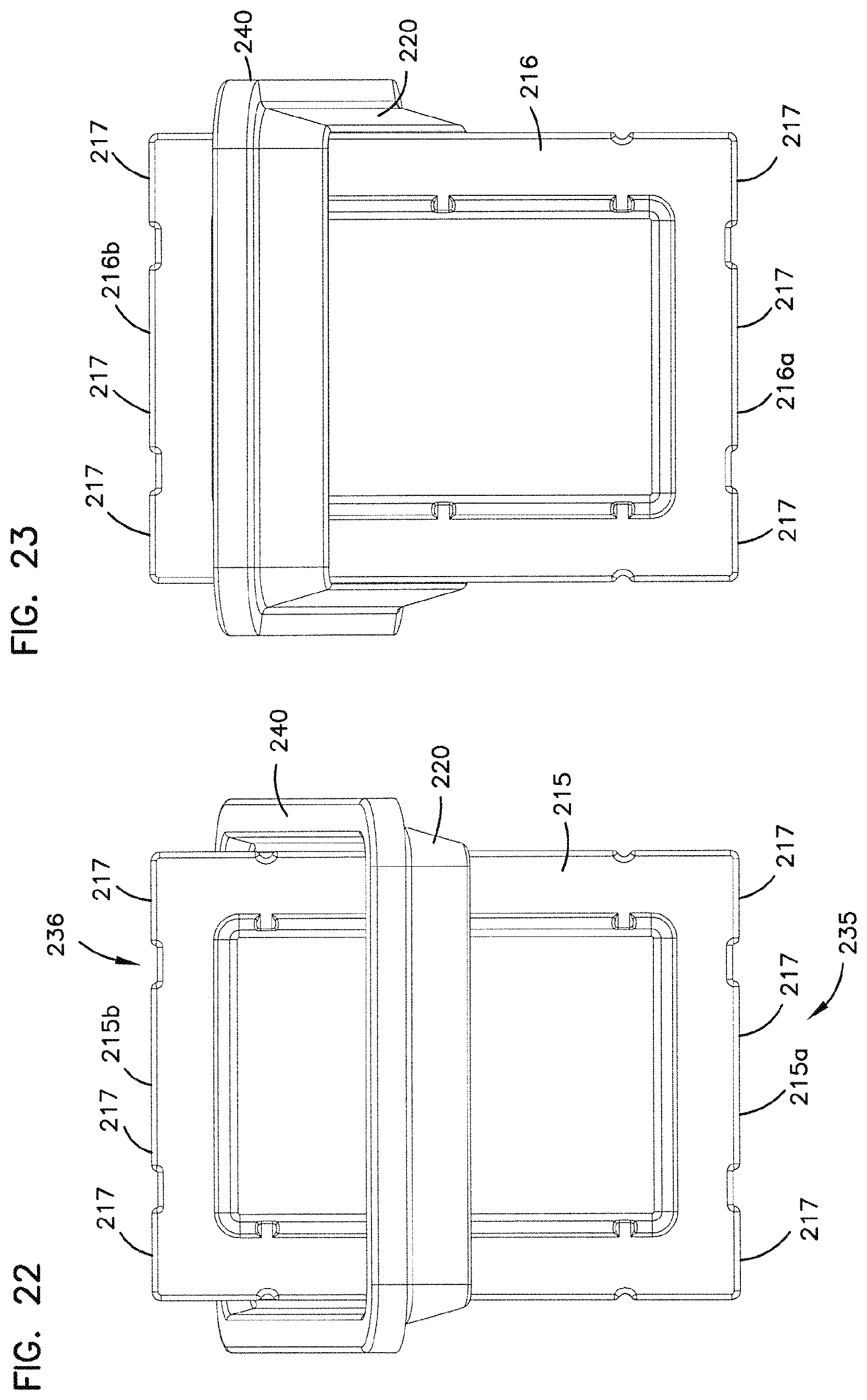
FIG. 22 is a first end elevational view of the cartridge of FIG. 20.
FIG. 23 is a second, opposite, end view if the filter cartridge of FIG. 20.
DETAILED DESCRIPTION
I. Z-Filter Media Configurations, Generally
Air cleaners according to the present disclosure utilize a z-filter media construction. In general the term "z-filter construction" as used herein, and variants thereof, is meant to refer to a filter construction in which individual ones of corrugated, folded or otherwise formed filter flutes are used to define sets of longitudinal, typically parallel, inlet and outlet filter flutes for fluid flow through the media; the fluid flowing along the length of flutes between opposite inlet and outlet ends (or flow faces) on the media, during filtering. Some examples of z-filter media are provided in U.S. Pat. Nos. 5,820,646; 5,772,883; 5,902,364; 5,792,247; 5,895,574; 6,210,469; 6,190,432; 6,350,296; 6,179,890; and 6,235,195. The complete disclosures of these 10 cited references are incorporated herein by reference.
One type of z-filter media, uses two specific separate media components which are joined together, to form a media construction. The two components are: (1) a fluted (typically corrugated) media sheet; and (2) a facing media sheet. The facing media sheet is typically non-corrugated, however it can be corrugated, for example perpendicularly to the flute direction as described in U.S. Provisional 60/543,804 filed Feb. 11, 2004, incorporated herein by reference.
In typical preferred applications as described herein, the media pack comprises stacked strips (each strip, sometimes, called a single facer strip, being a section of fluted (corrugated) sheet secured to facing sheet) each strip extending generally (or approximately) in a plane parallel to the other strips. Such arrangements are described for example in U.S. Provisional Applications 60/599,686, filed Aug. 6, 2004; 60/600,081, filed Aug. 9, 2004; 60/602,721, filed Aug. 18, 2004; and 60/616,364, filed Oct. 5, 2004, the complete disclosures of which are incorporated herein by reference. An example is described, for example, in connection with FIG. 6 of U.S. Provisional 60/616,364, and related descriptions. Stacked arrangements according to the present disclosure can be made in general in accord with the descriptions therein.
Particular arrangements shown herein are "blocked" stacked arrangements, in that each end or side face of the stacked arrangement extends perpendicularly to adjacent faces. Such arrangements are shown for example in U.S. Provisional Application 60/616,364, filed Oct. 5, 2004, FIG. 6. Alternate arrangements can be used, for example, in which instead of being blocked, the layers of single facer sheet are stacked offset from one another to create a slanted arrangement.
In typical arrangements, the flutes extend between opposite flow faces, one being an inlet flow face and the opposite being an outlet flow face. Opposite ends of the strips are typically sealed, for example by being secured within end pieces. This is described in U.S. Provisional Patent Application 60/616,364, at FIG. 64, for example.
A housing seal is provided between the media pack and the air cleaner housing, as described below.
II. Manufacture of Stacked Media Configurations Using Fluted Media, Generally
A process for manufacturing stacked media configurations using fluted media, is described in U.S. Provisional Application 60/616,364 in section II. Such techniques can be utilized to generate media packs useable in arrangements according to the present disclosure.
III. An Example Air Cleaner System, FIGS. 1-13
A. General System of Use.
The principles and arrangements described herein are useable in a variety of systems. One particular system is depicted schematically in FIG. 1, generally at 1. In FIG. 1, equipment 2, such as a vehicle 2a having an engine 3 with some defined rated air flow demand, for example in the range of 50 cfm to 2000 cfm (cubic feet per minute) (i.e., 1.4-57 cubic meters/minute) is shown schematically. Although alternatives are possible, the equipment 2 may, for example, comprise a bus, an over-the-highway truck, an off-road vehicle, a tractor, a light-duty or medium-duty truck, or a marine vehicle such as a power boat. The engine 3 powers the equipment 2 upon fuel combustion. In FIG. 1, air flow is shown drawn into the engine 3 at an air intake at region 5. An optional turbo 6 is shown in phantom, as optionally boosting the air intake to the engine 3. The turbo 6 is shown downstream from an air cleaner 10, although alternate arrangement are possible.
The air cleaner 10 has a serviceable (i.e., removable and replaceable) filter cartridge 12 and is shown in the air inlet stream to the engine 3. In general, in operation, air is drawn in at arrow 14 into the air cleaner 10 and through the filter cartridge 12. Upon passage through the air cleaner 10, selected particles and contaminants are removed from the air. The cleaned air then flows downstream at arrow 16 into the intake 5. From there, the air flow is directed into the engine 3.
In a typical air cleaner 10, the filter cartridge 12 is a serviceable component. That is, the cartridge 12 is removable and replaceable within the air cleaner 10. This allows the cartridge 12 to be serviced, by removal and replacement, with respect to remainder of air cleaner 10, when the cartridge 12 becomes sufficiently loaded with dust or other contaminant, to require servicing.
B. An Example Air Cleaner Arrangement, FIGS. 2-13.
In FIG. 2, a cross-sectional, schematic, view of an air cleaner arrangement according to the present disclosure. Referring to FIG. 2, air cleaner arrangement 50 comprises housing 50a including inlet section 51 and outlet section 52. The inlet section 51 and outlet section 52 are secured to one another along housing separation region 53. Clamps 54 or other arrangements, can be used to secure connection at separation region 53.
For the arrangement shown, housing separation region 53 comprises a flange 55 on the inlet section 51, and a flange 56 on the outlet section 52 sized and configured to engage one another. Unhooking clamps 54 allows separation of flanges 55, 56 (and thus sections 51, 52) to obtain service access to an interior of housing 50a.
The inlet section 51 includes an air flow inlet 58 and a filter cartridge receiving section 59. The outlet section 52 includes a filter cartridge receiving section 69 and an outlet tube 70.
For the particular arrangement shown, the inlet tube 58 and outlet tube 70 extend in generally opposite directions from one another. Alternate constructions are possible.
In a typical assembly, inside of outlet tube 70, or in related duct work, at or near region 72, a probe of a mass air flow sensor system (MAFS) could be positioned, to evaluate air flow in outlet tube 70.
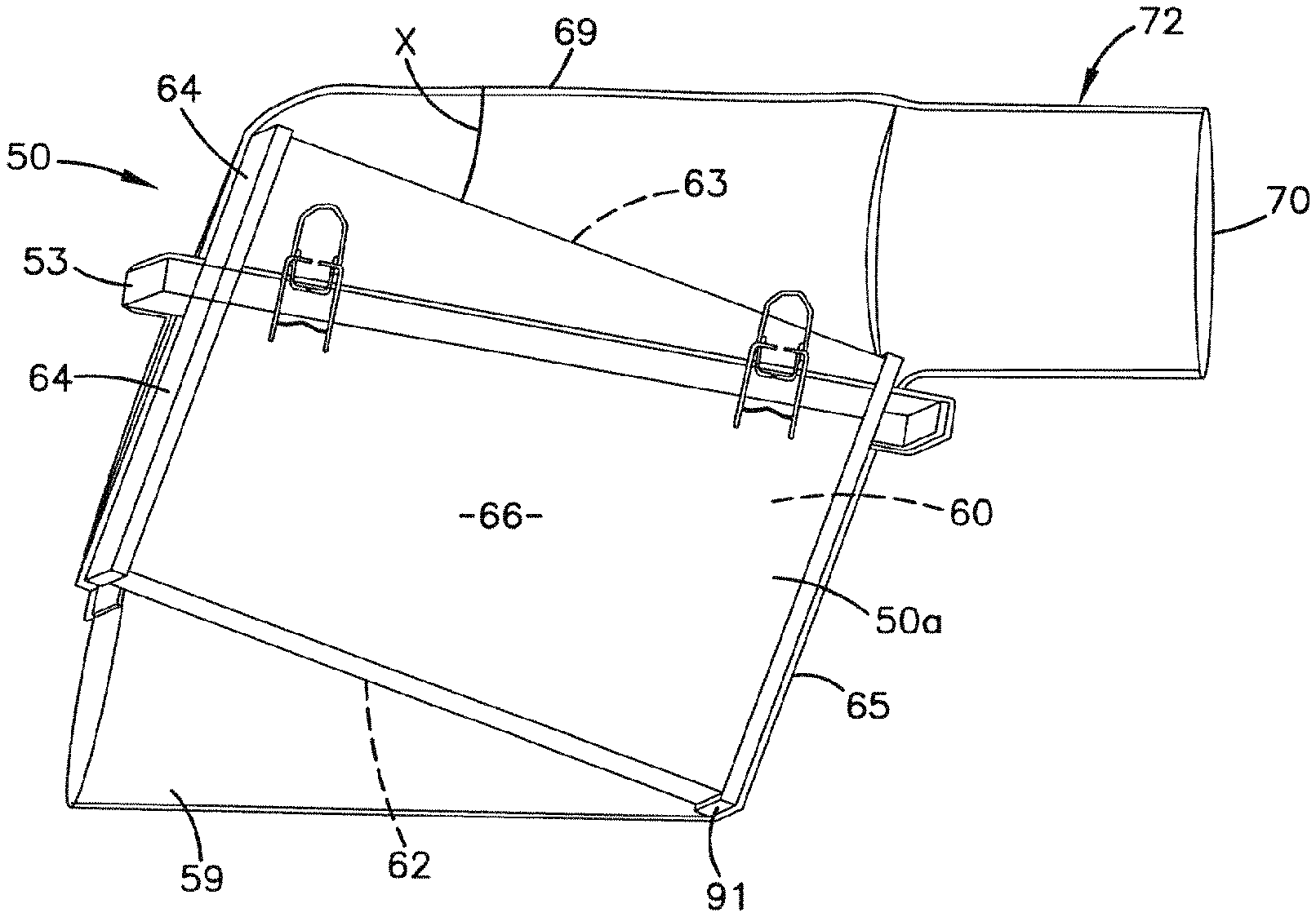
In FIG. 3, a side elevational view of air cleaner arrangement 50 is shown. In FIG. 4 an end view of air cleaner 50, directed toward inlet 58 is shown. In FIG. 4, a portion of a filter cartridge 60 positioned inside of air cleaner housing 50a is shown.
In FIG. 5, a schematic depiction of housing 50a is shown, with the housing 50a shown in a see-through form, so internally positioned filter cartridge 60 can be seen. Referring to FIG. 5, cartridge 60 comprises a z-filter media pack 61 having a inlet face 62, an outlet face 63, opposite ends 64, 65 and a pair of opposite faces 66, 67. Ends 64, 65 generally correspond to end sealant portions closing ends of single facer media forming the media pack 60.
Opposite faces 66, 67 are shown substantially uncovered, however a sheet of material or protective covering could be provided at these locations.
Generally, air is filtered by entering media pack 61 at inlet face 62 and exiting at opposite outlet face 63.
In FIG. 6, a side elevational view of the arrangement 50 as shown in FIG. 5, is depicted. In FIG. 7, a cross-sectional view of the arrangement shown in FIG. 6 is depicted.
It is desirable to configure air cleaner housing 50a and to position cartridge 60 therein, in a manner avoiding undesirable levels of air turbulence in region 72, which would negatively effect the operation of the MAFS. This is facilitated by: 1. Providing a stacked arrangement for cartridge 60 in which a coiled arrangement of corrugated media secured to facing media is avoided, but rather stacked strips of corrugated sheet secured to facing sheets are used, with each strip positioned at least approximately in a plane parallel to other strips. 2. Positioning outlet flow face 63, FIG. 6, partially angled toward outlet tube 70 as opposed to within a plane of separation region 53. Preferably the angle X between the outlet flow face 63 and outlet tube 70 is at least 10.degree. typically at least 15.degree. and often within the range of 15.degree. to 80.degree., inclusive, for example 15.degree.-40.degree., inclusive. A variety of arrangements can be used to position the cartridge 60 as shown schematically in FIG. 2.
An example of mounting is shown in FIG. 8. Referring to FIG. 8, housing seal arrangement 86 is shown on media pack 61 of cartridge 60. The seal arrangement 86 could be configured to be positioned between flanges 55, 56, for sealing. The seal arrangement 86 is positioned in a plane not parallel to inlet face 62 and outlet face 63, in extension across a face that would correspond to the face viewable at 66, FIG. 6. In general, this face would comprise a first one of a sheet of facing or fluted (typically corrugated) material, and the opposite face, typically, a second one of sheet of facing or fluted (typically corrugated) material, although coverings or other materials can be provided.
The angle between the seal arrangement 86 and the outlet face 63 is generally shown at Y, FIG. 8, and would typically be at least 5.degree. and usually within the range of 8.degree. to 45.degree., inclusive, for example 8.degree.-20.degree., inclusive.
It is noted that for the arrangement of FIGS. 1 and 2, at least 10% of the volume of the media pack 81 is positioned in each of: the inlet section 51 and the outlet section 52. Often at least 15% of each is so located.
Referring to FIG. 7, it is noted that for the arrangement shown, apex 90 of cartridge 61 is positioned at a highest location. Apex 90 comprises a corner or vertex formed between outlet flow face 63 and end 64.
Similarly, apex 91 is positioned in section 59, i.e., at a lowest location. Apex 91 comprises a corner diagonally opposite apex 90, and comprises a corner between inlet face 62 and end 65.
Attention is now directed to FIG. 9. In FIG. 9 a schematic perspective view of the filter cartridge 95, useable as cartridge 60. Referring to FIG. 9, cartridge 95 comprises media pack 96 with opposite flow faces 98, 99. The media pack 96 would typically and preferably comprise a blocked stacked arrangement of z-filter media strips, each strip comprising a section of corrugated sheet secured to a section of facing sheet. Ends of the strips form opposite end faces 101, 102. The end faces 101, 102 would typically be sealed, for example by covering with end pieces as shown.
Housing seal arrangement 105 is viewable. The housing seal arrangement 105 includes sections 106, 107 extending across ends 101, 102, respectively. It also includes an extension 110 and opposite extension 111, not viewable in FIG. 9, for engagement with the housing.
In FIG. 10, the side view of cartridge 95 is depicted. The view of FIG. 10 would be toward side 112, FIG. 9, but inverted. In FIG. 10, a pair of spaced extensions or spacers 117, extending between ends 101, 102 is viewable. A second pair could also be positioned oppositely, i.e., on a surface 113, FIG. 11, opposite to surface 112.
In FIG. 11, a view toward end section 107 is provided. In FIG. 12 the view is toward end section 106 (inverted relatively to FIG. 9). In FIG. 13 the view toward outlet face 99 is shown.
In FIGS. 10-13, dimensions are shown in millimeters (and inches in brackets) to indicate an example size. Of course a variety of alternate sizes can be made.
IV. A Second Example Air Cleaner Systems, FIGS. 14-23
In FIGS. 14-23, a second example air cleaner system is depicted. In FIGS. 14-19, the air cleaner assembly 200 is viewable. In FIGS. 20-23, a removable and replaceable filter cartridge 201 useable in the air cleaner 200 is provided. Many of the features of the air cleaner 200 are analogous features to those discussed previously for air cleaner 50, FIGS. 2-8, and many of the features are provided with the same reference numerals in FIGS. 14-19. Thus the air cleaner arrangement 200 comprises housing 50a including an inlet section 51 and an outlet section 52. The inlet section 51 and outlet section 52 are secured to one another along housing separation region 53. Clamps 54 are used to secure separation region 53. Referring to FIG. 19, the housing separation 53 comprises a flange 55 on the inlet section 51, and a flange 56 on the outlet section 52, sized and configured to engage one another. Unhooking clamps 54, FIGS. 14-18, allow separation of flanges 55, 56 (and thus section 51 and 52) to obtain service access to an interior housing 50a. This allows for servicing of cartridge 201, for example by replacement, FIG. 19.
The inlet section 51 includes an air flow inlet 58 and a filter cartridge receiving section 59. The outlet section 52 includes a filter cartridge receiving section 69 and an outlet tube 70. For the particular arrangement shown, the inlet tube 58 and outlet tube 70 extend in generally opposite directions from one another. Alternate constructions are possible.
In the assembly, inside the tube 70, (or in a related duct work), at or near region 72, a probe of a mass air flow sensor system (MAFS) could be positioned, to evaluate air flow in outlet tube 70.
Referring to FIG. 19, attention is directed to the following features. First housing section 51 includes a lower support ledge or shelf arrangement 210 comprising shelves 211 and 212. When filter cartridge 201 is positioned within housing 50a, opposite side panels 215, 216 will respectively rest on ledges 211, 212, for support. Thus cartridge 201 is not suspended by the seal arrangement 220. Rather, the cartridge 201 is supported by engagement of the panels 215, 216 with the ledge arrangement 210.
The filter cartridge 201 will be generally understood by reference to FIGS. 20-23. Referring first to FIG. 20, cartridge 201 comprises a media pack 230 having side panels 215 and 216. The media pack 230 would generally comprise a stacked arrangement of single facer material comprising fluted (corrugated) media secured to facing media with opposite upstream and downstream flute seal arrangements appropriate to define a series of inlet flutes and outlet flutes extending between opposite faces 235, 236 in accord with previous discussions. This prevents unfiltered air entering face 235 from leaving via face 236, without passage through media, for filtering. The particular media pack 230 depicted schematically in FIG. 20, is a "blocked" stacked arrangement, again meaning that no face or side is slanted, rather each engages adjacent ones at 90.degree. angles. Of course, as discussed above slanted arrangements are possible with the principles described herein.
For the particular example shown in FIG. 20, face 235 would be an inlet face for air flow, and opposite face 236 would be an outlet face for filtered air. The panels 215, 216 would typically and preferably be molded-in-place, to seal ends of the single facer strips within the media pack 230. Typically panels 215, 216 would be molded from a polyurethane such as a foamed polyurethane.
In a typical construction approach, the same mold would be used for panels 215, 216, with two molding steps.
Referring to FIG. 20, filter cartridge 201 includes peripheral, perimeter housing seal arrangement 220 thereon. The particular seal arrangement 220 depicted, extends completely around the media pack 230, separating the media pack into an upstream section 230u and a downstream 230d. For a typical example, the seal arrangement 220 would comprise a single integral molded-in-place seal, typically a molded polymeric material such as a foamed polyurethane, made in a one-shot mold process and applied after the panels 215, 216 are in place on the media pack 230. The seal arrangement 220 is provided with an outer flange 240 which, when cartridge 201 is positioned within housing 50a, FIG. 19, is compressed between flanges 55, 56 to form a seal. Such a compression seal is generally referred to herein as a "axial" seal, or by similar terminology, since the force of compression on the seal member 220 is generally parallel to an access of air flow direction through the media pack 201.
The example housing seal arrangements described herein have no rigid structural member embedded therein, and each is molded from a single polymeric material, such as polyurethane. Thus, the housing seal arrangement 220 can be described as consisting essentially of molded polyurethane, typically foamed polyurethane.
Referring to FIG. 21, seal flange 240 generally extends at an angle Y relative to the outlet face 236 as previously discussed, i.e., typically at least 5.degree. and usually within the range of 8.degree. to 45.degree., inclusive, for example 8.degree.-20.degree., inclusive. For the particular example shown the range would typically be 8.degree.-15.degree., for example about 10.degree.. More generally stated, the angle Y is greater than 0.degree., and usually not greater than 45.degree..
Referring to FIGS. 22 and 23, the configuration of the panels 215, 216 is shown. In particular each panel 215 includes opposite edges 215a, 215b, edge 215a being adjacent inlet face 235 and edge 215b being adjacent outlet face 236. Edges 215a and 215b are provided with projection regions 217 which extend beyond an adjacent face of the media pack. These regions 217 will engage the housing as shown in FIG. 19, for secure positioning of the cartridge, during installation. In particular regions 217 along edge 215a, will engage ledge 211, FIG. 19. Regions 217 along edge 215b will engage cover ledge 250, FIG. 19, to help secure the cartridge against unintended motion. Ledge 215 is opposite ledge 211, and panel 215 is secured therebetween.
Referring to FIG. 23, panel 216 analogously includes opposite edges 216a and 216b, with projections 217. The projections 217 along edge 216a will be engaged by ledge 212 of FIG. 19, during installation. Projections 217 along edge 216b can be made to not engage structure within the housing, although if desired a ledge structure can be provided adjacent opposite corners, to help secure the cartridge 201 in position.
In FIG. 19, seal arrangement 220 can be seen in cross-section. The seal arrangement 220 includes a base 260, by which the media pack 201 and panels 215, 216 are engaged. Flange 240, which is compressed to form the seal, is secured to base 260. Typically the flange 240 is molded at end base 260, meaning the two are jointly molded from a single material, at the same time.
A trough 261 is provided between the flange 240 and the media pack 201 and panels 215, 216. The trough 261 generally extends toward base 260 and is surrounded by at least a portion of the flange 240. The trough 260 is positioned to receive a flange projection 270 therein, during installation, FIG. 19. The flange projection 270 is secured on one of the housing sections 51, 52, in this example the downstream housing section 52.
The trough 261 is generally configured to have a maximum depth of at least 3 mm, usually at least 4 mm and typically at least 5 mm. Examples would be 5-14 mm, although alternatives are possible.
Still referring to FIG. 19, flange 55 is configured to receive therein seal arrangement 220 during installation. Flange 55 includes an outer projection 275 which will surround flange 240, during installation. Flange 275 is of a sufficient length to bottom out against a portion of cover section 52, during installation.
Still referring to FIG. 19, cover section 52 includes flange arrangement 56 including inner projection 270 and outer projection 278. The inner projection 270, again, is sized to extend into trough 261. The outer projection 278 is sized to extend around projection 275, during installation. Flange 279 extending between projections 270, 278, provides a surface against which flange 275 can bottom out, during installation.
It is noted that radially outwardly projecting flange 279 includes projection 280 thereon, sized to press into axial seal flange 240, to help ensure seal. Such a projection will generally extend into the flange 240 a distance corresponding to at least 2% of the compressed thickness of the flange 240 between opposite walls 240a, 240b, FIG. 21.
Referring to FIG. 19, angle X indicates the angle between the outlet flow face 236 and the outlet tube 70. The angle is typically at least 10.degree., usually at least 15.degree. and often within the range of 15.degree. to 80.degree., inclusive, for example 15.degree.-45.degree.. As a result of angle X, outlet face 236 can be viewed as tipped toward outlet tube 70, with an apex of the media pack indicated at 300 corresponding to a portion of the media pack 201 highest within housing 50a, and positioned to tip face 236 toward outlet tube 70.
For the example of FIGS. 14-23, some example dimensions are provided, as follows: AA=217.1 mm; AB=328.0 mm; AC=301.5 mm; AD=500.9 mm; AE=328.4 mm; AF=112.1 mm.
An example material useable for both the seal and the side moldings described herein is polyurethane. An example polyurethane characterized is a foamed polyurethane which will increase in volume during use. Preferred ones increase by at least 40% in volume, to fill the mold cavities (typically at least 80% in volume) and having an as-molded density of no greater than 30 lbs/cu.ft (0.48 g/cc), typically no greater than 22 lbs/cu.ft. (0.35 g/cc) and usually with in the range of 10 lbs/cu.ft (0.16 g/cc) to 22 lbs/cu.ft (0.35 g/cc); and, a hardness (Shore A) typically of not greater than 30, preferably not greater than 25 and typically within the range of 10 to 22. Of course polyurethanes outside of this range can be used, but the characterized ones are advantageous for manufacturing and handling.
* * * * *
D00000
D00001
D00002
D00003
D00004
D00005
D00006
D00007
D00008
D00009
D00010
D00011
D00012
D00013
D00014
D00015
D00016
D00017
D00018
D00019
D00020
XML
uspto.report is an independent third-party trademark research tool that is not affiliated, endorsed, or sponsored by the United States Patent and Trademark Office (USPTO) or any other governmental organization. The information provided by uspto.report is based on publicly available data at the time of writing and is intended for informational purposes only.
While we strive to provide accurate and up-to-date information, we do not guarantee the accuracy, completeness, reliability, or suitability of the information displayed on this site. The use of this site is at your own risk. Any reliance you place on such information is therefore strictly at your own risk.
All official trademark data, including owner information, should be verified by visiting the official USPTO website at www.uspto.gov. This site is not intended to replace professional legal advice and should not be used as a substitute for consulting with a legal professional who is knowledgeable about trademark law.