Abdominal aortic aneurysms: systems and methods of use
Berra , et al. December 15, 2
U.S. patent number 10,864,097 [Application Number 16/141,322] was granted by the patent office on 2020-12-15 for abdominal aortic aneurysms: systems and methods of use. This patent grant is currently assigned to Bolton Medical, Inc.. The grantee listed for this patent is Bolton Medical, Inc.. Invention is credited to Humberto Berra, John C. Canning, Timothy Lostetter, Scott L. Rush, Bryan White.


View All Diagrams
| United States Patent | 10,864,097 |
| Berra , et al. | December 15, 2020 |
Abdominal aortic aneurysms: systems and methods of use
Abstract
A method of releasing a bare stent of a stent graft includes moving a lumen, to which a proximal apex capture portion of an apex capture device is fixed, the proximal apex capture portion defining a radial restraint, along a major axis between a first position, in which tines of the proximal apex capture portion are mated with slots of a distal apex capture portion and overlie bosses extending radially from a major axis of the apex capture device, and a second position, in which the tines are not mated with the slots and do not overlie the bosses, to thereby release apices of a bare stent from a space defined by the tines, the bosses and the distal apex capture portion.
| Inventors: | Berra; Humberto (Sunrise, FL), White; Bryan (Weston, FL), Lostetter; Timothy (Sunrise, FL), Rush; Scott L. (Sunrise, FL), Canning; John C. (Sunrise, FL) | ||||||||||
|---|---|---|---|---|---|---|---|---|---|---|---|
| Applicant: |
|
||||||||||
| Assignee: | Bolton Medical, Inc. (Sunrise,
FL) |
||||||||||
| Family ID: | 1000005242181 | ||||||||||
| Appl. No.: | 16/141,322 | ||||||||||
| Filed: | September 25, 2018 |
Prior Publication Data
| Document Identifier | Publication Date | |
|---|---|---|
| US 20190159914 A1 | May 30, 2019 | |
Related U.S. Patent Documents
| Application Number | Filing Date | Patent Number | Issue Date | ||
|---|---|---|---|---|---|
| 15166818 | May 27, 2016 | 10105248 | |||
| 12459387 | Jun 14, 2016 | 9364314 | |||
| 61077031 | Jun 30, 2008 | ||||
| 61164545 | Mar 30, 2009 | ||||
| Current U.S. Class: | 1/1 |
| Current CPC Class: | A61F 2/07 (20130101); A61F 2/89 (20130101); A61F 2/966 (20130101); A61F 2/95 (20130101); A61F 2/848 (20130101); A61M 39/06 (20130101); A61F 2002/9665 (20130101); A61F 2210/0014 (20130101); A61F 2210/0076 (20130101); A61F 2220/0041 (20130101); A61F 2002/075 (20130101); A61F 2220/0075 (20130101); A61F 2220/0008 (20130101); A61F 2220/0016 (20130101); A61F 2/9517 (20200501); A61F 2002/9505 (20130101); A61F 2230/0054 (20130101); A61F 2/91 (20130101); A61F 2002/9511 (20130101); A61F 2002/8483 (20130101) |
| Current International Class: | A61F 2/95 (20130101); A61F 2/07 (20130101); A61F 2/966 (20130101); A61M 39/06 (20060101); A61F 2/848 (20130101); A61F 2/89 (20130101); A61F 2/91 (20130101) |
| Field of Search: | ;623/1.11-1.13,1.23,1.35,2.11,6.12,6.11 ;606/200,108,107 |
References Cited [Referenced By]
U.S. Patent Documents
| 3416531 | December 1968 | Edwards |
| 3485234 | December 1969 | Stevens |
| 3502069 | March 1970 | Silverman |
| 3868956 | March 1975 | Alfidi et al. |
| 4351333 | September 1982 | Lazarus et al. |
| 4425919 | January 1984 | Alston, Jr. et al. |
| 4487808 | December 1984 | Lambert |
| 4515593 | May 1985 | Norton |
| 4516972 | May 1985 | Samson |
| 4534363 | August 1985 | Gold |
| 4572186 | February 1986 | Gould et al. |
| 4580568 | April 1986 | Gianturco |
| 4634432 | January 1987 | Kocak |
| 4655771 | April 1987 | Wallsten |
| 4665906 | May 1987 | Jervis |
| 4665918 | May 1987 | Garza et al. |
| 4705511 | November 1987 | Kocak |
| 4787899 | November 1988 | Lazarus |
| 4817613 | April 1989 | Jaraczewski et al. |
| 4990151 | February 1991 | Wallsten et al. |
| 5019057 | May 1991 | Truckai |
| 5041126 | August 1991 | Gianturco |
| 5057092 | October 1991 | Webster, Jr. |
| 5067957 | November 1991 | Jervis |
| 5104399 | April 1992 | Lazarus |
| 5154701 | October 1992 | Cheer et al. |
| 5158543 | October 1992 | Lazarus |
| 5176652 | January 1993 | Littrell |
| 5176660 | January 1993 | Truckai |
| 5201757 | April 1993 | Heyn et al. |
| 5254105 | October 1993 | Haaga |
| 5282824 | February 1994 | Gianturco |
| 5290295 | March 1994 | Querals et al. |
| 5292331 | March 1994 | Boneau |
| 5306263 | April 1994 | Voda |
| 5324306 | June 1994 | Makower et al. |
| 5334164 | August 1994 | Guy et al. |
| 5334168 | August 1994 | Hemmer |
| 5338295 | August 1994 | Cornelius et al. |
| 5342384 | August 1994 | Sugarbaker |
| 5358493 | October 1994 | Schweich, Jr. et al. |
| 5380304 | January 1995 | Parker |
| 5387235 | February 1995 | Chuter |
| 5397345 | March 1995 | Lazarus |
| 5405377 | April 1995 | Cragg |
| 5415664 | May 1995 | Pinchuk |
| 5433723 | July 1995 | Lindenberg et al. |
| 5456713 | October 1995 | Chuter |
| 5458615 | October 1995 | Klemm et al. |
| 5464449 | November 1995 | Ryan et al. |
| 5474563 | December 1995 | Myler et al. |
| 5480423 | January 1996 | Ravenscroft et al. |
| 5489295 | February 1996 | Piplani et al. |
| 5507769 | April 1996 | Marin et al. |
| 5507771 | April 1996 | Gianturco |
| 5522881 | June 1996 | Lentz |
| 5522882 | June 1996 | Gaterud et al. |
| 5531715 | July 1996 | Engelson et al. |
| 5533987 | July 1996 | Pray et al. |
| 5534007 | July 1996 | St. Germain et al. |
| 5540712 | July 1996 | Kleshinski et al. |
| 5545210 | August 1996 | Hess et al. |
| 5549565 | August 1996 | Ryan et al. |
| 5562726 | October 1996 | Chuter |
| 5562728 | October 1996 | Lazarus et al. |
| 5569218 | October 1996 | Berg |
| 5571135 | November 1996 | Fraser et al. |
| 5575816 | November 1996 | Rudnick et al. |
| 5575817 | November 1996 | Martin |
| 5582614 | December 1996 | Feingold |
| 5591194 | January 1997 | Berthiaume |
| 5591195 | January 1997 | Taheri et al. |
| 5597378 | January 1997 | Jervis |
| 5601568 | February 1997 | Chevillon et al. |
| 5607442 | March 1997 | Fischell et al. |
| 5609625 | March 1997 | Piplani et al. |
| 5609627 | March 1997 | Goicoechea et al. |
| 5613974 | March 1997 | Andreas et al. |
| 5618270 | April 1997 | Orcjola |
| 5628754 | May 1997 | Shevlin et al. |
| 5628783 | May 1997 | Quiachon et al. |
| 5632763 | May 1997 | Glastra |
| 5639278 | June 1997 | Dereume et al. |
| 5658263 | August 1997 | Dang et al. |
| 5662675 | September 1997 | Polanskyj Stockert et al. |
| 5662700 | September 1997 | Lazarus |
| 5674208 | October 1997 | Berg et al. |
| 5676696 | October 1997 | Marcade |
| 5683449 | November 1997 | Marcade |
| 5693086 | December 1997 | Goicocchca et al. |
| 5695517 | December 1997 | Marin et al. |
| 5700269 | December 1997 | Pinchuk et al. |
| 5707376 | January 1998 | Kavteladze et al. |
| 5709703 | January 1998 | Lukic et al. |
| 5713917 | February 1998 | Leonhardt et al. |
| 5716365 | February 1998 | Goicoechea et al. |
| 5716393 | February 1998 | Lindenberg et al. |
| 5720776 | February 1998 | Chuter et al. |
| 5723003 | March 1998 | Winston et al. |
| 5730733 | March 1998 | Mortier et al. |
| 5733267 | March 1998 | Del Toro |
| 5735859 | April 1998 | Fischell et al. |
| 5749921 | May 1998 | Lenker et al. |
| 5755778 | May 1998 | Kleshinski |
| 5776142 | July 1998 | Gunderson |
| 5782811 | July 1998 | Samson et al. |
| 5782904 | July 1998 | White et al. |
| 5782909 | July 1998 | Quiachon et al. |
| 5788707 | August 1998 | Del Toro et al. |
| 5792144 | August 1998 | Fischell et al. |
| 5800515 | September 1998 | Nadal et al. |
| 5800517 | September 1998 | Anderson et al. |
| 5800520 | September 1998 | Fogarty et al. |
| 5824036 | October 1998 | Lauterjung |
| 5824037 | October 1998 | Fogarty et al. |
| 5824039 | October 1998 | Piplani et al. |
| 5824040 | October 1998 | Cox et al. |
| 5824041 | October 1998 | Lenker et al. |
| 5824042 | October 1998 | Lombardi et al. |
| 5824044 | October 1998 | Quiachon et al. |
| 5843158 | December 1998 | Lenker et al. |
| 5843160 | December 1998 | Rhodes |
| 5843164 | December 1998 | Frantzen et al. |
| 5843167 | December 1998 | Dwyer et al. |
| 5851228 | December 1998 | Pinheiro |
| 5860998 | January 1999 | Robinson et al. |
| 5871536 | February 1999 | Lazarus |
| 5891110 | April 1999 | Larson et al. |
| 5891114 | April 1999 | Chien et al. |
| 5893868 | April 1999 | Hanson et al. |
| 5899892 | May 1999 | Mortier et al. |
| 5902334 | May 1999 | Dwyer et al. |
| 5904713 | May 1999 | Leschinsky |
| 5906619 | May 1999 | Olson et al. |
| 5910101 | June 1999 | Andrews et al. |
| 5911715 | June 1999 | Berg et al. |
| 5916263 | June 1999 | Goicoechea et al. |
| 5938696 | August 1999 | Goicoechea et al. |
| 5944726 | August 1999 | Blaeser et al. |
| 5947939 | September 1999 | Mortier et al. |
| 5951495 | September 1999 | Berg et al. |
| 5954651 | September 1999 | Berg et al. |
| 5957949 | September 1999 | Leonhardt et al. |
| 5961511 | October 1999 | Mortier et al. |
| 5968069 | October 1999 | Dusbabek et al. |
| 5984955 | November 1999 | Wissclink |
| 5993481 | November 1999 | Marcade et al. |
| 6004310 | December 1999 | Bardsley et al. |
| 6004328 | December 1999 | Solar |
| 6004347 | December 1999 | McNamara et al. |
| 6019778 | February 2000 | Wilson et al. |
| 6024763 | February 2000 | Lenker et al. |
| 6039749 | March 2000 | Marin et al. |
| 6039758 | March 2000 | Quiachon et al. |
| 6039759 | March 2000 | Carpentier et al. |
| 6045557 | April 2000 | White et al. |
| 6051020 | April 2000 | Goicocchca et al. |
| 6053943 | April 2000 | Edwin et al. |
| 6063112 | May 2000 | Sgro |
| 6071307 | June 2000 | Rhee et al. |
| 6077297 | June 2000 | Robinson et al. |
| 6099548 | August 2000 | Taheri |
| 6099558 | August 2000 | White et al. |
| 6099559 | August 2000 | Nolting |
| 6110191 | August 2000 | Dehdashtian et al. |
| 6110198 | August 2000 | Fogarty et al. |
| 6117167 | September 2000 | Goicoechea et al. |
| 6120480 | September 2000 | Zhang et al. |
| 6123723 | September 2000 | Konya et al. |
| 6126685 | October 2000 | Lenker et al. |
| 6152944 | November 2000 | Holman et al. |
| 6165163 | December 2000 | Chien et al. |
| 6165213 | December 2000 | Goicoechea et al. |
| 6168616 | January 2001 | Brown, III |
| 6168623 | January 2001 | Fogarty et al. |
| 6183481 | February 2001 | Lee et al. |
| 6183505 | February 2001 | Mobil, Jr. et al. |
| 6183506 | February 2001 | Penn et al. |
| 6193705 | February 2001 | Mortier et al. |
| 6200336 | March 2001 | Pavcnik et al. |
| 6200339 | March 2001 | Leschinsky et al. |
| 6203550 | March 2001 | Olson |
| 6203568 | March 2001 | Lombardi et al. |
| 6210435 | April 2001 | Piplani et al. |
| 6212422 | April 2001 | Berg et al. |
| 6213976 | April 2001 | Trerotola |
| 6214038 | April 2001 | Piplani et al. |
| 6221079 | April 2001 | Magovern et al. |
| 6221102 | April 2001 | Baker et al. |
| 6224609 | May 2001 | Ressemann et al. |
| 6228063 | May 2001 | Aboul-Hosn |
| 6231601 | May 2001 | Myers et al. |
| 6238430 | May 2001 | Klumb et al. |
| 6245052 | June 2001 | Orth et al. |
| 6248112 | June 2001 | Gambale et al. |
| 6248116 | June 2001 | Chevillon et al. |
| 6251132 | June 2001 | Ravenscroft et al. |
| 6254609 | July 2001 | Vrba et al. |
| 6267775 | July 2001 | Clerc et al. |
| 6270521 | August 2001 | Fischcll et al. |
| 6273909 | August 2001 | Kugler et al. |
| 6280464 | August 2001 | Hayashi |
| 6280466 | August 2001 | Kugler et al. |
| 6280467 | August 2001 | Leonhardt |
| 6285903 | September 2001 | Rosenthal et al. |
| 6287315 | September 2001 | Wijeratne et al. |
| 6302906 | October 2001 | Goicoechea et al. |
| 6302907 | October 2001 | Hijlkema |
| 6306141 | October 2001 | Jervis |
| 6312458 | November 2001 | Golds |
| 6319275 | November 2001 | Lashinski et al. |
| 6319278 | November 2001 | Quinn |
| 6322585 | November 2001 | Khosravi et al. |
| 6334869 | January 2002 | Leonhardt et al. |
| 6338709 | January 2002 | Geoffrion et al. |
| 6342066 | January 2002 | Toro et al. |
| 6344044 | February 2002 | Fulkerson et al. |
| 6344052 | February 2002 | Greenan et al. |
| 6346118 | February 2002 | Baker et al. |
| 6350278 | February 2002 | Lenker et al. |
| 6355056 | March 2002 | Pinheiro |
| 6355060 | March 2002 | Lenker et al. |
| 6368345 | April 2002 | Dehdashtian et al. |
| 6375675 | April 2002 | Dehdashtian et al. |
| 6375676 | April 2002 | Cox |
| 6379372 | April 2002 | Dehdashtian et al. |
| 6389946 | May 2002 | Frid et al. |
| 6395017 | May 2002 | Dwyer et al. |
| 6395022 | May 2002 | Piplani et al. |
| 6398802 | June 2002 | Yee |
| 6402781 | June 2002 | Langberg et al. |
| 6416490 | July 2002 | Ellis et al. |
| 6416542 | July 2002 | Marcade et al. |
| 6419686 | July 2002 | McLeod et al. |
| 6425898 | July 2002 | Wilson et al. |
| 6443979 | September 2002 | Stalker et al. |
| 6443980 | September 2002 | Wang et al. |
| 6450988 | September 2002 | Bradshaw |
| 6451053 | September 2002 | Dehdashtian et al. |
| 6454796 | September 2002 | Barkman et al. |
| 6458867 | October 2002 | Wang et al. |
| 6464684 | October 2002 | Galdonik |
| 6464719 | October 2002 | Jayaraman |
| 6464721 | October 2002 | Marcade et al. |
| 6478818 | November 2002 | Taheri |
| 6488700 | December 2002 | Klumb et al. |
| 6503274 | January 2003 | Howanec, Jr. et al. |
| 6505066 | January 2003 | Berg et al. |
| 6514282 | February 2003 | Inoue |
| 6517571 | February 2003 | Brauker et al. |
| 6517572 | February 2003 | Kugler et al. |
| 6517573 | February 2003 | Pollock et al. |
| 6520951 | February 2003 | Carrillo, Jr. et al. |
| 6520986 | February 2003 | Martin et al. |
| 6524335 | February 2003 | Hartley et al. |
| 6524336 | February 2003 | Papazolgou et al. |
| 6533753 | March 2003 | Haarstad et al. |
| 6540698 | April 2003 | Ishii |
| 6540778 | April 2003 | Quiachon et al. |
| 6551350 | April 2003 | Thornton et al. |
| 6562022 | May 2003 | Hoste et al. |
| 6565596 | May 2003 | White et al. |
| 6565597 | May 2003 | Fearnot et al. |
| 6575994 | June 2003 | Marin et al. |
| 6576007 | June 2003 | Dehdashtian et al. |
| 6576009 | June 2003 | Ryan et al. |
| 6582458 | June 2003 | White et al. |
| 6582460 | June 2003 | Cryer |
| 6592526 | July 2003 | Lenker |
| 6613073 | September 2003 | White et al. |
| 6616626 | September 2003 | Crank et al. |
| 6620126 | September 2003 | Unsworth et al. |
| 6641606 | November 2003 | Ouriel et al. |
| 6652571 | November 2003 | White et al. |
| 6652572 | November 2003 | Kugler et al. |
| 6660033 | December 2003 | Marcade et al. |
| 6676666 | January 2004 | Vrba et al. |
| 6682536 | January 2004 | Vardi et al. |
| 6682537 | January 2004 | Ouriel et al. |
| 6682557 | January 2004 | Quiachon et al. |
| 6685736 | February 2004 | White et al. |
| 6689152 | February 2004 | Balceta et al. |
| 6689158 | February 2004 | White et al. |
| 6692458 | February 2004 | Forman et al. |
| 6692483 | February 2004 | Vardi et al. |
| 6692512 | February 2004 | Jang |
| 6695875 | February 2004 | Stelter et al. |
| 6706033 | March 2004 | Martinez et al. |
| 6726712 | April 2004 | Raeder-Devens et al. |
| 6733519 | May 2004 | Lashinski et al. |
| 6733523 | May 2004 | Shaolian et al. |
| 6755856 | June 2004 | Fierens et al. |
| 6761731 | July 2004 | Majercak |
| 6790222 | September 2004 | Kugler et al. |
| 6802860 | October 2004 | Cosgrove et al. |
| 6808529 | October 2004 | Fulkerson |
| 6811559 | November 2004 | Thornton |
| 6814748 | November 2004 | Baker et al. |
| 6821291 | November 2004 | Bolea et al. |
| 6827710 | December 2004 | Mooney et al. |
| 6827711 | December 2004 | Sunseri |
| 6830575 | December 2004 | Stenzel et al. |
| 6843803 | January 2005 | Ryan et al. |
| 6849084 | February 2005 | Rabkin et al. |
| 6849088 | February 2005 | Dehdashtian et al. |
| 6858034 | February 2005 | Hijlkema et al. |
| 6859986 | March 2005 | Jackson et al. |
| 6860901 | March 2005 | Baker et al. |
| 6863668 | March 2005 | Gillespie et al. |
| 6866660 | March 2005 | Garabedian et al. |
| 6866669 | March 2005 | Buzzard et al. |
| 6871085 | March 2005 | Sommer |
| 6884260 | April 2005 | Kugler et al. |
| 6890348 | May 2005 | Sydney et al. |
| 6911039 | June 2005 | Shiu et al. |
| 6916335 | July 2005 | Kanji |
| 6918925 | July 2005 | Tehrani |
| 6932829 | August 2005 | Majercak |
| 6938646 | September 2005 | Litton |
| 6939371 | September 2005 | Kugler et al. |
| 6942691 | September 2005 | Chuter |
| 6945989 | September 2005 | Betelia et al. |
| 6945990 | September 2005 | Greenan |
| 6964679 | November 2005 | Marcade et al. |
| 6984244 | January 2006 | Perez et al. |
| 6989024 | January 2006 | Hebert et al. |
| 6994722 | February 2006 | DiCarlo |
| 7001420 | February 2006 | Speck et al. |
| 7011647 | March 2006 | Purdy et al. |
| 7014653 | March 2006 | Ouriel |
| 7025773 | April 2006 | Gittings et al. |
| 7052511 | May 2006 | Weldon et al. |
| 7070582 | July 2006 | Freyman et al. |
| 7105016 | September 2006 | Shiu et al. |
| 7112217 | September 2006 | Kugler et al. |
| 7115134 | October 2006 | Chambers |
| 7125419 | October 2006 | Sequin et al. |
| 7147657 | December 2006 | Chiang et al. |
| 7147660 | December 2006 | Chobotov et al. |
| 7160318 | January 2007 | Greenberg et al. |
| 7163552 | January 2007 | Diaz |
| 7166125 | January 2007 | Baker et al. |
| 7169170 | January 2007 | Widenhouse |
| 7195639 | March 2007 | Quiachon et al. |
| 7225518 | June 2007 | Eidenschink et al. |
| 7238197 | July 2007 | Sequin et al. |
| 7264632 | September 2007 | Wright et al. |
| 7294147 | November 2007 | Hartley |
| 7351256 | April 2008 | Hojeibane et al. |
| 7435253 | October 2008 | Hartley et al. |
| 7451765 | November 2008 | Adler |
| 7708771 | May 2010 | Chuter et al. |
| 7717950 | May 2010 | Greenan |
| 7722663 | May 2010 | Austin |
| 7763063 | July 2010 | Arbefeuille et al. |
| 7766962 | August 2010 | Quinn |
| 7780716 | August 2010 | Pappas et al. |
| 7794489 | September 2010 | Shumer et al. |
| 7799065 | September 2010 | Pappas |
| 7815671 | October 2010 | Wright et al. |
| 7837724 | November 2010 | Keeble et al. |
| 8007605 | August 2011 | Arbefeuille et al. |
| 8043354 | October 2011 | Greenberg et al. |
| 8062345 | November 2011 | Ouellette et al. |
| 8062349 | November 2011 | Moore et al. |
| 8070790 | December 2011 | Berra et al. |
| 8083792 | December 2011 | Boucher et al. |
| 8206427 | June 2012 | Ryan et al. |
| 8241346 | August 2012 | Chobotov |
| 8292943 | October 2012 | Berra et al. |
| 8308790 | November 2012 | Arbefeuille et al. |
| 8317854 | November 2012 | Ryan et al. |
| 8333797 | December 2012 | Goodson, IV et al. |
| 8449595 | May 2013 | Ouellette et al. |
| 8500792 | August 2013 | Berra |
| 8579963 | November 2013 | Tabor |
| 8636788 | January 2014 | Arbefeuille et al. |
| 8672992 | March 2014 | Off |
| 8702787 | April 2014 | Arbefeuille |
| 8709060 | April 2014 | Osborne |
| 8734501 | May 2014 | Hartley et al. |
| 8740963 | June 2014 | Arbefeuille et al. |
| 8998970 | April 2015 | Arbefeuille et al. |
| 9101506 | August 2015 | Arbefeuille et al. |
| 9173755 | November 2015 | Berra et al. |
| 9198786 | December 2015 | Moore et al. |
| 9220617 | December 2015 | Berra |
| 9320631 | April 2016 | Moore et al. |
| 9333104 | May 2016 | Ouellette et al. |
| 9364314 | June 2016 | Berra et al. |
| 9408734 | August 2016 | Arbefeuille et al. |
| 9408735 | August 2016 | Arbefeuille et al. |
| 9439751 | September 2016 | White et al. |
| 9554929 | January 2017 | Arbefeuille et al. |
| 9561124 | February 2017 | Arbefeuille et al. |
| 9592112 | March 2017 | Arbefeuille et al. |
| 9655712 | May 2017 | Berra et al. |
| 9827123 | November 2017 | Arbefeuille et al. |
| 9877857 | January 2018 | Arbefeuille et al. |
| 9907686 | March 2018 | Ouellette et al. |
| 9913743 | March 2018 | Arbefeuille et al. |
| 9925080 | March 2018 | Arbefeuille et al. |
| 10105248 | October 2018 | Berra |
| 10105250 | October 2018 | Berra |
| 10182930 | January 2019 | Moore et al. |
| 10307275 | June 2019 | Berra et al. |
| 10390929 | August 2019 | Arbefeuille et al. |
| 10646365 | May 2020 | Berra et al. |
| 2001/0000801 | May 2001 | Miller et al. |
| 2001/0001833 | May 2001 | Ravenscroft et al. |
| 2001/0034549 | October 2001 | Bartholf et al. |
| 2001/0049547 | December 2001 | Moore |
| 2002/0007193 | January 2002 | Tanner et al. |
| 2002/0013617 | January 2002 | Matsutani et al. |
| 2002/0016597 | February 2002 | Dwyer et al. |
| 2002/0016627 | February 2002 | Golds |
| 2002/0035394 | March 2002 | Fierens |
| 2002/0045929 | April 2002 | Diaz |
| 2002/0052643 | May 2002 | Wholey et al. |
| 2002/0052660 | May 2002 | Greenhalgh |
| 2002/0062133 | May 2002 | Gilson et al. |
| 2002/0072755 | June 2002 | Bigus et al. |
| 2002/0082523 | June 2002 | Kinsella et al. |
| 2002/0082674 | June 2002 | Anson et al. |
| 2002/0091439 | July 2002 | Baker et al. |
| 2002/0095140 | July 2002 | Lootz et al. |
| 2002/0107561 | August 2002 | Pinheiro |
| 2002/0108621 | August 2002 | Berg et al. |
| 2002/0111671 | August 2002 | Stenzel |
| 2002/0138133 | September 2002 | Lenz et al. |
| 2002/0156518 | October 2002 | Tehrani |
| 2002/0156522 | October 2002 | Ivancev et al. |
| 2002/0161424 | October 2002 | Rapacki et al. |
| 2002/0165554 | November 2002 | Dworschak et al. |
| 2002/0188344 | December 2002 | Bolea |
| 2002/0198587 | December 2002 | Greenberg et al. |
| 2003/0028237 | February 2003 | Sullivan et al. |
| 2003/0074049 | April 2003 | Hoganson et al. |
| 2003/0083734 | May 2003 | Friedrich et al. |
| 2003/0088305 | May 2003 | Van Schie et al. |
| 2003/0114910 | June 2003 | Juhani Laakso et al. |
| 2003/0120263 | June 2003 | Ouriel et al. |
| 2003/0120333 | June 2003 | Ouriel et al. |
| 2003/0135259 | July 2003 | Simso |
| 2003/0135269 | July 2003 | Swanstrom |
| 2003/0139803 | July 2003 | Sequin et al. |
| 2003/0163156 | August 2003 | Hebert et al. |
| 2003/0163193 | August 2003 | Widenhouse |
| 2003/0176911 | September 2003 | Iancea et al. |
| 2003/0176912 | September 2003 | Chuter et al. |
| 2003/0191516 | October 2003 | Weldon et al. |
| 2003/0195614 | October 2003 | Ryan et al. |
| 2003/0199966 | October 2003 | Shiu et al. |
| 2003/0199967 | October 2003 | Hartley et al. |
| 2003/0199973 | October 2003 | Chuter et al. |
| 2003/0212431 | November 2003 | Brady et al. |
| 2003/0220682 | November 2003 | Kujawski |
| 2003/0233140 | December 2003 | Hartley et al. |
| 2003/0236564 | December 2003 | Majercak |
| 2003/0236565 | December 2003 | DiMatteo et al. |
| 2004/0073284 | April 2004 | Bates et al. |
| 2004/0073289 | April 2004 | Hartley |
| 2004/0093063 | May 2004 | Wright et al. |
| 2004/0098084 | May 2004 | Hartley et al. |
| 2004/0106974 | June 2004 | Greenberg et al. |
| 2004/0117003 | June 2004 | Ouriel et al. |
| 2004/0148007 | July 2004 | Jackson et al. |
| 2004/0148009 | July 2004 | Buzzard et al. |
| 2004/0193141 | September 2004 | Leopold et al. |
| 2004/0193244 | September 2004 | Hartley et al. |
| 2004/0193245 | September 2004 | Deem et al. |
| 2004/0193252 | September 2004 | Perez |
| 2004/0199240 | October 2004 | Dorn et al. |
| 2004/0210194 | October 2004 | Bonnette et al. |
| 2004/0230284 | November 2004 | Headley et al. |
| 2004/0230286 | November 2004 | Moore et al. |
| 2004/0236403 | November 2004 | Leonhardt et al. |
| 2004/0236407 | November 2004 | Fierens et al. |
| 2004/0267281 | December 2004 | Harari et al. |
| 2005/0021125 | January 2005 | Stack et al. |
| 2005/0027305 | February 2005 | Shiu et al. |
| 2005/0033406 | February 2005 | Barnhart et al. |
| 2005/0038495 | February 2005 | Greenan |
| 2005/0049667 | March 2005 | Arbefeuille et al. |
| 2005/0049674 | March 2005 | Berra et al. |
| 2005/0060016 | March 2005 | Wu et al. |
| 2005/0080476 | April 2005 | Gunderson et al. |
| 2005/0080477 | April 2005 | Sydney et al. |
| 2005/0085789 | April 2005 | Khan et al. |
| 2005/0096726 | May 2005 | Sequin et al. |
| 2005/0107862 | May 2005 | Ohlenschlaeger |
| 2005/0131523 | June 2005 | Bashiri et al. |
| 2005/0149166 | July 2005 | Schaeffer et al. |
| 2005/0159803 | July 2005 | Lad et al. |
| 2005/0159804 | July 2005 | Lad et al. |
| 2005/0171597 | August 2005 | Boatman et al. |
| 2005/0171598 | August 2005 | Schaeffer |
| 2005/0177222 | August 2005 | Mead |
| 2005/0183259 | August 2005 | Eidenschink et al. |
| 2005/0192659 | September 2005 | Dahl et al. |
| 2005/0222668 | October 2005 | Schaeffer et al. |
| 2005/0283223 | December 2005 | Greenan |
| 2005/0288764 | December 2005 | Snow et al. |
| 2006/0004433 | January 2006 | Greenberg et al. |
| 2006/0020319 | January 2006 | Kim et al. |
| 2006/0020320 | January 2006 | Shaolian et al. |
| 2006/0058864 | March 2006 | Schaeffer et al. |
| 2006/0127439 | June 2006 | Mattes et al. |
| 2006/0129169 | June 2006 | Fogarty et al. |
| 2006/0129224 | June 2006 | Arbefeuille et al. |
| 2006/0135961 | June 2006 | Rosenman et al. |
| 2006/0155366 | July 2006 | LaDuca et al. |
| 2006/0178726 | August 2006 | Douglas |
| 2006/0178733 | August 2006 | Pinchuk et al. |
| 2006/0188408 | August 2006 | Arbefeuille et al. |
| 2006/0195172 | August 2006 | Luo et al. |
| 2006/0200110 | September 2006 | Lentz et al. |
| 2006/0212105 | September 2006 | Dorn et al. |
| 2006/0265047 | November 2006 | Dorn |
| 2006/0276872 | December 2006 | Arbefeuille et al. |
| 2006/0282150 | December 2006 | Olson et al. |
| 2007/0021822 | January 2007 | Boatman |
| 2007/0048348 | March 2007 | Atanasoska et al. |
| 2007/0053952 | March 2007 | Chen et al. |
| 2007/0055338 | March 2007 | Dorn |
| 2007/0055340 | March 2007 | Pryor |
| 2007/0055341 | March 2007 | Edoga et al. |
| 2007/0055345 | March 2007 | Arbefeuille |
| 2007/0055347 | March 2007 | Arbefeuille |
| 2007/0083252 | April 2007 | McDonald |
| 2007/0100422 | May 2007 | Shumer et al. |
| 2007/0100425 | May 2007 | Sequin et al. |
| 2007/0123972 | May 2007 | Greenberg et al. |
| 2007/0135818 | June 2007 | Moore et al. |
| 2007/0135889 | June 2007 | Moore et al. |
| 2007/0142894 | June 2007 | Moore et al. |
| 2007/0156223 | July 2007 | Vaughan |
| 2007/0156228 | July 2007 | Majercak et al. |
| 2007/0162109 | July 2007 | Davila et al. |
| 2007/0163668 | July 2007 | Arbefeuille et al. |
| 2007/0168014 | July 2007 | Jimenez et al. |
| 2007/0173929 | July 2007 | Boucher et al. |
| 2007/0179592 | August 2007 | Schaeffer |
| 2007/0179593 | August 2007 | Fierens et al. |
| 2007/0179601 | August 2007 | Fierens et al. |
| 2007/0198078 | August 2007 | Berra et al. |
| 2007/0203566 | August 2007 | Arbefeuille et al. |
| 2007/0207186 | September 2007 | Scanlon et al. |
| 2007/0213800 | September 2007 | Fierens et al. |
| 2007/0219620 | September 2007 | Eells et al. |
| 2007/0244545 | October 2007 | Birdsall et al. |
| 2008/0021538 | January 2008 | Wright et al. |
| 2008/0027528 | January 2008 | Jagger et al. |
| 2008/0046065 | February 2008 | Hartley et al. |
| 2008/0065011 | March 2008 | Marchand et al. |
| 2008/0071343 | March 2008 | Mayberry et al. |
| 2008/0077226 | March 2008 | Ouellette et al. |
| 2008/0077227 | March 2008 | Ouellette et al. |
| 2008/0082158 | April 2008 | Tseng et al. |
| 2008/0091260 | April 2008 | Pomeranz et al. |
| 2008/0114441 | May 2008 | Rust et al. |
| 2008/0132996 | June 2008 | Drasler et al. |
| 2008/0157017 | July 2008 | Macatangay et al. |
| 2008/0172122 | July 2008 | Mayberry et al. |
| 2008/0195191 | August 2008 | Luo et al. |
| 2008/0208175 | August 2008 | Beckman et al. |
| 2008/0262590 | October 2008 | Murray |
| 2008/0264102 | October 2008 | Berra |
| 2008/0269865 | October 2008 | Snow et al. |
| 2009/0163951 | June 2009 | Simmons et al. |
| 2009/0254165 | October 2009 | Tabor et al. |
| 2010/0004730 | January 2010 | Benjamin et al. |
| 2010/0030255 | February 2010 | Berra et al. |
| 2010/0030318 | February 2010 | Berra |
| 2010/0049313 | February 2010 | Alon et al. |
| 2010/0234932 | September 2010 | Arbefeuille et al. |
| 2010/0274226 | October 2010 | Hansen |
| 2010/0274340 | October 2010 | Hartley et al. |
| 2011/0054405 | March 2011 | Whiting et al. |
| 2011/0071614 | March 2011 | Majercak |
| 2011/0087318 | April 2011 | Daugherty et al. |
| 2011/0208288 | August 2011 | Arbefeuille et al. |
| 2011/0218607 | September 2011 | Arbefeuille et al. |
| 2011/0251664 | October 2011 | Acosta de Acevedo |
| 2011/0307049 | December 2011 | Kao |
| 2011/0313503 | December 2011 | Berra et al. |
| 2012/0022636 | January 2012 | Chobotov |
| 2012/0123517 | May 2012 | Ouellette et al. |
| 2012/0123528 | May 2012 | Knippel et al. |
| 2012/0143305 | June 2012 | Berra et al. |
| 2012/0245672 | September 2012 | Arbefeuille et al. |
| 2012/0271408 | October 2012 | Colgan et al. |
| 2012/0296413 | November 2012 | Arbefeuille et al. |
| 2013/0274856 | October 2013 | Arbefeuille et al. |
| 2013/0289693 | October 2013 | Maggard et al. |
| 2013/0325099 | December 2013 | Berra |
| 2013/0331924 | December 2013 | Ouellette et al. |
| 2014/0135890 | May 2014 | Berra |
| 2014/0135892 | May 2014 | Arbefeuille et al. |
| 2014/0135896 | May 2014 | Arbefeuille et al. |
| 2014/0148890 | May 2014 | Ouellette et al. |
| 2014/0243952 | August 2014 | Parodi et al. |
| 2014/0277340 | September 2014 | White et al. |
| 2014/0288627 | September 2014 | Ouellette et al. |
| 2014/0316510 | October 2014 | Berra |
| 2015/0173922 | June 2015 | Arbefeuille et al. |
| 2015/0202066 | July 2015 | Berra et al. |
| 2015/0202068 | July 2015 | Arbefeuille et al. |
| 2015/0272755 | October 2015 | Arbefeuille et al. |
| 2016/0045350 | February 2016 | Berra et al. |
| 2016/0081787 | March 2016 | Parodi et al. |
| 2016/0135961 | May 2016 | Aeschlimann et al. |
| 2016/0270901 | September 2016 | Berra et al. |
| 2016/0270936 | September 2016 | Berra |
| 2016/0310301 | October 2016 | Moore et al. |
| 2016/0338867 | November 2016 | White et al. |
| 2017/0000600 | January 2017 | Berra et al. |
| 2017/0100232 | April 2017 | Arbefeuille et al. |
| 2017/0100271 | April 2017 | Arbefeuille et al. |
| 2017/0135807 | May 2017 | Arbefeuille et al. |
| 2017/0151076 | June 2017 | Arbefeuille et al. |
| 2017/0165090 | June 2017 | Arbefeuille et al. |
| 2017/0165091 | June 2017 | Arbefeuille et al. |
| 2017/0281332 | October 2017 | Lostetter |
| 2017/0281382 | October 2017 | Lostetter |
| 2017/0340433 | November 2017 | Berra |
| 2017/0340462 | November 2017 | Lostetter |
| 2018/0071123 | March 2018 | Arbefeuille |
| 2018/0110638 | April 2018 | Berra et al. |
| 2018/0140448 | May 2018 | Arbefeuille et al. |
| 2018/0206972 | July 2018 | Arbefeuille et al. |
| 2019/0159914 | May 2019 | Berra et al. |
| 2019/0167412 | June 2019 | Berra et al. |
| 2019/0254848 | August 2019 | Berra et al. |
| 2020/0121483 | April 2020 | White et al. |
| 2451136 | Oct 2001 | CN | |||
| 2518466 | Oct 2002 | CN | |||
| 197 53 123 | Aug 1999 | DE | |||
| 10 2006 05374 | Apr 2008 | DE | |||
| 0 510 851 | Oct 1992 | EP | |||
| 0 873 733 | Oct 1998 | EP | |||
| 0 960 607 | Dec 1999 | EP | |||
| 0 696 447 | Jan 2000 | EP | |||
| 0 990 426 | Apr 2000 | EP | |||
| 1 177 779 | Feb 2002 | EP | |||
| 1 302 178 | Apr 2003 | EP | |||
| 1 358 903 | Nov 2003 | EP | |||
| 1 369 098 | Dec 2003 | EP | |||
| 1 522 277 | Apr 2005 | EP | |||
| 1 772 120 | Apr 2007 | EP | |||
| 1 923 024 | May 2008 | EP | |||
| 1 929 979 | Jun 2008 | EP | |||
| 1 440 673 | Sep 2008 | EP | |||
| 1 982 677 | Oct 2008 | EP | |||
| 1 508 313 | Dec 2008 | EP | |||
| 3 040 058 | Jul 2016 | EP | |||
| 2 714 816 | Jul 1995 | FR | |||
| 2 722 678 | Jan 1996 | FR | |||
| 2 779 939 | Dec 1999 | FR | |||
| WO-91/12838 | Sep 1991 | WO | |||
| WO-94/01149 | Jan 1994 | WO | |||
| WO 95/23008 | Aug 1995 | WO | |||
| WO 96/09013 | Mar 1996 | WO | |||
| WO 96/23455 | Aug 1996 | WO | |||
| WO 96/31174 | Oct 1996 | WO | |||
| WO 96/38101 | Dec 1996 | WO | |||
| WO 97/10778 | Mar 1997 | WO | |||
| WO 97/33532 | Sep 1997 | WO | |||
| WO 98/20811 | May 1998 | WO | |||
| WO 98/23242 | Jun 1998 | WO | |||
| WO 98/42276 | Oct 1998 | WO | |||
| WO 98/53761 | Dec 1998 | WO | |||
| WO-99/07308 | Feb 1999 | WO | |||
| WO 99/25273 | May 1999 | WO | |||
| WO 99/37242 | Jul 1999 | WO | |||
| WO 99/65420 | Dec 1999 | WO | |||
| WO 00/02615 | Jan 2000 | WO | |||
| WO 00/30562 | Jun 2000 | WO | |||
| WO-00/76423 | Dec 2000 | WO | |||
| WO 00/78248 | Dec 2000 | WO | |||
| WO 01/17602 | Mar 2001 | WO | |||
| WO 01/21102 | Mar 2001 | WO | |||
| WO 02/28316 | Apr 2002 | WO | |||
| WO 03/015662 | Feb 2003 | WO | |||
| WO 2004/000169 | Dec 2003 | WO | |||
| WO 2004/002370 | Jan 2004 | WO | |||
| WO 2004/071352 | Aug 2004 | WO | |||
| 2004/091452 | Oct 2004 | WO | |||
| WO-2005/018732 | Mar 2005 | WO | |||
| WO 2005/023149 | Mar 2005 | WO | |||
| WO 2005/034808 | Apr 2005 | WO | |||
| WO 2005/058409 | Jun 2005 | WO | |||
| WO 2005/067819 | Jul 2005 | WO | |||
| WO 2005/081936 | Sep 2005 | WO | |||
| WO 2005/112821 | Dec 2005 | WO | |||
| WO 2006/019551 | Feb 2006 | WO | |||
| WO 2006/088638 | Aug 2006 | WO | |||
| WO 2006/125382 | Nov 2006 | WO | |||
| WO 2007/008533 | Jan 2007 | WO | |||
| WO 2007/028086 | Mar 2007 | WO | |||
| 2007/076114 | Jul 2007 | WO | |||
| WO 2007/092276 | Aug 2007 | WO | |||
| WO 2007/123956 | Nov 2007 | WO | |||
| WO 2008/031103 | Mar 2008 | WO | |||
| WO 2008/066923 | Jun 2008 | WO | |||
| WO-2008/085772 | Jul 2008 | WO | |||
| WO 2008/098252 | Aug 2008 | WO | |||
| WO 2009/023221 | Feb 2009 | WO | |||
| WO 2009/124124 | Oct 2009 | WO | |||
| WO 2010/005524 | Jan 2010 | WO | |||
| WO-2010/027485 | Mar 2010 | WO | |||
| WO 2010/042950 | Apr 2010 | WO | |||
| WO 2010/105195 | Sep 2010 | WO | |||
| WO-2011/056638 | May 2011 | WO | |||
| WO 2013/154749 | Oct 2013 | WO | |||
| WO 2014/149022 | Sep 2014 | WO | |||
| WO 2017/176674 | Oct 2017 | WO | |||
Other References
|
Criado, F.J., "EVAR at 20: The Unfolding of a Revolutionary New Technique That Changed Everything," J. Endovasc. Ther., 17:789-796 (2010). cited by applicant . Parodi, J.C., et al., "Transfemoral Intraluminal Graft Implantation for Abdominal Aortic Aneurysms," Ann. Vasc. Surg., 5:491-499 (1991). cited by applicant . Notification of Transmittal of The International Search Report and the Written Opinion or the International Searching Authority, or the Declaration for International Application No. PCT/US2009/003896, dated Jan. 12, 2010. cited by applicant . Notification Concerning Transmittal of International Preliminary Report on Patentability for International Application No. PCT/US2009/003896; dated Jan. 13, 2011. cited by applicant . Office Action, U.S. Appl. No. 12/459,387, dated Jul. 11, 2012. cited by applicant . Office Action, U.S. Appl. No. 12/459,387, dated Mar. 14, 2013. cited by applicant . Office Action, U.S. Appl. No. 12/459,387, dated Jan. 6, 2014. cited by applicant . Office Action, U.S. Appl. No. 12/459,387 dated Aug. 14, 2014. cited by applicant . Office Action, U.S. Appl. No. 12/459,387; dated Oct. 30, 2015. cited by applicant . Office Action, U.S. Appl. No. 12/459,387, dated Apr. 19, 2016. cited by applicant . Notice of Allowance, U.S. Appl. No. 12/459,387, dated May 3, 2016. cited by applicant . Final Office Action, U.S. Appl. No. 15/167,055, dated Jul. 12, 2017. cited by applicant . Office Action, U.S. Appl. No. 15/167,055, dated Jan. 11, 2017. cited by applicant . Office Action, U.S. Appl. No. 15/166,818, dated Feb. 12, 2018. cited by applicant . Office Action, U.S. Appl. No. 15/167,055, dated Jan. 16, 2018. cited by applicant . Notice of Allowance, U.S. Appl. No. 15/166,818, dated Jul. 17, 2018. cited by applicant . Notice of Allowance for U.S. Appl. No. 12/459,387 dated May 3, 2016. cited by applicant . U.S. Office Action for U.S. Appl. No. 15/167,055 dated Jul. 31, 2018. cited by applicant . U.S. Office Action for U.S. Appl. No. 12/459,387, dated May 8, 2012. cited by applicant. |
Primary Examiner: Weisberg; Amy R
Attorney, Agent or Firm: Foley Hoag LLP Pierce; N. Scott
Parent Case Text
RELATED APPLICATIONS
This application is a divisional of Ser. No. 15/166,818 filed on May 27, 2016, now U.S. Pat. No. 10,105,248, issued Oct. 23, 2018, which is a divisional of U.S. application Ser. No. 12/459,387, filed on Jun. 30, 2009, now U.S. Pat. No. 9,364,314, issued Jun. 14, 2016, which claims the benefit of U.S. Provisional Application No. 61/077,031, filed on Jun. 30, 2008, and U.S. Provisional Application No. 61/164,545, filed on Mar. 30, 2009. The entire teachings of the above applications are incorporated herein by reference.
Claims
What is claimed is:
1. A method of releasing a bare stent of a stent graft, comprising the steps of moving a control lumen, to which a proximal apex capture portion of an apex capture device is fixed, the proximal apex capture portion defining pilot holes extending along a major axis of the lumen, from a first position, in which tines of the proximal apex capture portion are mated with a distal apex capture portion, and in which barbs extending distally from proximal apices of a bare stent of a stent graft are radially restrained by the pilot holes, and a second position, in which the tines are not mated with the distal apex capture portion, thereby releasing apices of a bare stent from a space defined at least in part by the tines and the distal apex capture portion, and releasing the barbs from radial restraint by the pilot holes.
2. The method of claim 1, wherein the distal apex capture portion defines slots that mate with the tines of the proximal apex capture portion when the control lumen is in the first position.
3. The method of claim 2, wherein the elongate member extends through the lumen.
4. The method of claim 1, wherein the barbs each extend distally from a proximal apex of the bare stent.
5. The method of claim 4, wherein the barbs are radially restrained by the pilot holes where the barbs extend from a bridge component of each respective proximal apex of the bare stent.
6. The method of claim 1, wherein the tines overlie bosses extending radially from the major axis of the distal capture portion, whereby the space from which the distal apices are released is defined by the tines, the bosses, and the distal apex capture portion.
7. A system for releasing a bare stent of a stent graft, comprising: a) a guidewire lumen having a proximal end and a distal end; b) a nose cone fixed to the distal end of the guidewire lumen, the nose cone having a proximal end and a distal end; c) a control lumen having a proximal end, a distal end, and a major axis, the control lumen extending circumferentially about the guidewire lumen and longitudinally moveable along the guidewire lumen; and d) an apex capture device, including i) a distal apex capture portion fixed to the guidewire lumen at the proximal end of the nose cone, and ii) a proximal apex capture portion fixed to the distal end of the control lumen, the proximal apex capture portion defining pilot holes and defining tines that extend distally from the remainder of the proximal apex capture portion and mate with distal capture portion when the control lumen is in a first position, and disengage from the distal capture portion when the control lumen is moved proximally along the guidewire lumen from the first position to a second position.
Description
BACKGROUND OF THE INVENTION
Stent graft delivery systems have been designed to treat abdominal aortic aneurysm (AAA) to minimize the diameter or "French" size of the portion to be inserted into the patient. This usually results in severe compression of very large stents into small diameter tubes or catheters. The drastic inward compression results in high longitudinal forces for loading the stent graft--pushing the pre-compressed stent into the delivery system sheath--and in high deployment forces--occurring when the stent graft is unsheathed at the time of clinical deployment. Other factors cumulatively add to this deployment force including, for example, friction between components of the delivery system handle and the amount of tortuosity in which the sheath is navigated through the patient's vessels.
Deployment accuracy is a term referring to the ability of a physician to choose a target site for stent graft placement within the patient and the ability to "accurately" deliver the stent at the implantation site, the accuracy being measured with respect to both the longitudinal and rotational position of the stent graft. High deployment forces reduce a physician's ability to control deployment accuracy. Other factors can adversely affect deployment accuracy and present additional problems that the physician must address or for which the physician must compensate. These include quality of viewing equipment (fluoroscopy) and rapid blood flow. It would be desirable, therefore, to provide a system that increases stent graft deployment accuracy.
"Pin-and-pull" is a term that has been used in the art to describe many early types of stent/stent graft delivery systems. In pin-and-pull systems, there are two main components: an inner support catheter (e.g., a tube or a rod); and an outer sheath. The outer sheath longitudinally slides over the inner support catheter and can be freely rotated around the inner support catheter (i.e., rotation is independent of longitudinal outer sheath motion). To load a stent graft therein, the inner support catheter is drawn proximally (towards user) so that an interior chamber is created at the distal end of the outer sheath. The stent graft is compressed radially and inserted into this chamber so that the outer sheath houses the compressed stent graft inside its distal end. In this configuration, the inner support catheter prevents the stent graft from moving in a direction towards the physician (proximally) when the outer sheath is retracted. Deployment of the stent graft occurs naturally when the outer sheath is retracted because the individual stents of the stent graft have an outward bias towards their respective fully expanded state.
When the physician is using a pin-and-pull device, the stent graft is maneuvered to the deployment site using fluoroscopy, for example. At this point, the physician is prepared to release the stent graft. The stent graft is deployed in the vessel by "pinning" the inner support catheter relative to the patient and "pulling" back on the outer sheath--thus deriving from these actions the "pin-and-pull" nomenclature.
Because the outer sheath is compressing the stent graft, movement of the outer sheath towards the physician tends to draw the stent graft in this direction. Thus, without the inner support catheter, the stent graft will not be deployed. Minimizing the deployment force allows the sheath to retract with greater ease. It is, therefore, desirable to have the sheath retract as easily as possible.
With high deployment forces, the physician has less control over the placement accuracy. The highest deployment force occurs when the sheath first begins to retract. Once the user has overcome the initial friction between the sheath and the compressed stent, the force then needed for deployment plummets. This rapid decline is almost instantaneous and, often, the physician is not able to react quickly enough to lower the force being supplied to the delivery system. This failure to react results in deployment of more of the stent graft than intended by the physician or in a deployment that fails to hit the intended target site (i.e., low deployment accuracy).
Some mechanisms have been employed to add control to stent graft deployment and minimize this rapid release of stored energy within the delivery system. These mechanisms include screw-type retraction of the stent sheath and/or incorporation of "stops" which prevent inadvertent release of the stent. The screw-type mechanisms slow down the release of the stored energy and help maintain better control of stent release. These screw-type mechanisms also can impart a mechanical advantage by converting the linear force to a torque force. Stop-type mechanisms do not affect conversion or lowering of the deployment force, but help by preventing any over-compensation of the force and any instantaneous release of the force. Neither of these, however, significantly increase deployment accuracy and an improvement in performance would be desirable.
Modular disassociation creates serious type III endoleaks, which can have significant clinical consequences. Creating a mechanical interaction, the modular pull out force will exceed clinical requirements. This type of securement significantly reduces the likelihood of this event. Also, this system does not require rotational alignment between the receiving and inserting components. This makes the mechanism substantially invisible to the doctor and does not add any complexity to the procedure. Further, the system prevents adverse complications during the procedure. By using a proximally facing fold in the graft, there is virtually no chance of accidental ensnarement of a guide wire during the procedure. (If loops or holes were placed in the first member, then a guidewire could potentially get caught without the physician being aware of that ensnarement.) Moreover, the folds in the graft create extra layers of material. Thus, if a securing component were to wear through some of the graft, there multiple layers of the graft will remain to prevent an endoleak. This includes the layer of graft on the inserting member. It is unlikely that wearing of the graft to create an endoleak would occur in both the catheter and catheter direction through three to four layers of material. Significantly, by having multiple engaging members of the second (inserting) stent graft, there is redundancy in the vessel repair system. Therefore, even if some members miss the pockets or even if some members fracture, the overall integrity of the system will still be intact. Further redundancy in the vessel repair system is present by providing multiple sets of folds in the first component. These folds can be at the very end of the stent graft as well as multiple folds moving up the length of the stent graft. This configuration and variants thereof can cover any leg prosthesis stent graft.
Thus, there is a need to develop new, useful and effective delivery systems, components and methods to treat AAA.
SUMMARY OF THE INVENTION
The present invention relates to delivery systems, components of delivery systems and methods of using the delivery systems and its components to treat vascular damage, in particular AAA.
In an embodiment, the invention is an apex capture device, comprising a proximal apex capture portion that includes a nose, wherein the nose defines at least one radial restraint that is substantially parallel to a major axis of the proximal capture portion, and a plurality of tines extending distally from the nose, the tines radially distributed about the major axis radial to a most proximal radial restraint and substantially parallel to the major axis; a distal apex capture portion defining slots distributed radially about the major axis, the slots mateable with the tines by relative movement of the proximal and distal apex capture portions along the major axis; a plurality of bosses extending radially from the major axis between the nose and the distal apex capture portion and aligned with the slots along the major axis in non-interfering relation with movement of the tines into mating relation with the slots; an elongate member to which the distal apex capture portion is fixed, the elongate member extending through the proximal apex capture portion and the plurality of bosses; and a catheter to which the proximal apex capture portion is fixed, through which the elongate member extends, whereby movement of the catheter causes movement of the proximal apex capture portion along the major axis between a first position, in which the tines are mated with the slots and overlie the bosses, and a second position, in which the tines are not mated with the slots and do not overlie the bosses.
In another embodiment, the invention is a method of releasing a bare stent of a stent graft, comprising the steps of moving a catheter to which a proximal apex capture portion of an apex capture device is fixed, the proximal apex capture portion defining a radial restraint, along a major axis between a first position, in which tines of the proximal apex capture portion are mated with slots of a distal apex capture portion and overlie bosses extending radially from a major axis of the apex capture device, and a second position, in which the tines are not mated with the slots and do not overlie the bosses, thereby releasing apices of a bare stent from a space defined by the tines, the bosses and the distal apex capture portion.
In a further embodiment, the invention is an apex capture device assembly, comprising a proximal apex capture portion that includes a nose, wherein the nose defines at least one radial restraint that is substantially parallel to a major axis of the proximal capture portion, and a plurality of tines extending distally from the nose, the tines radially distributed about the major axis radial to a most proximal radial restraint and substantially parallel to the major axis; a distal apex capture portion defining slots distributed radially about the major axis, the slots mateable with the tines by relative movement of the proximal and distal apex capture portions along the major axis; a plurality of bosses extending radially from the major axis between the nose and the distal apex capture portion and aligned with the slots along the major axis in non-interfering relation with movement of the times into mating relation with the slots; an elongate member to which the distal apex capture portion is fixed, the elongate member extending through the proximal apex capture portion and the plurality of bosses; a catheter to which the proximal apex capture portion is fixed, through which the elongate member extends, whereby movement of the catheter causes movement of the proximal apex portion along the major axis between a first position, in which the tines are mated with the slots and overlie the bosses, and a second position, in which the tines are not mated with the slots and do not overlie the bosses; a bare stent that includes struts linked by apices, the struts extending between the tines, a portion of the apices extending between the bosses and the distal apex capture portion when the times are mated to the slots; and at least one suprarenal barb extending from the stent into the radial restraint.
In yet another embodiment, the invention is a stent graft system, comprising a luminal graft component; a bare stent component including a plurality of struts joined by proximal and distal apices connecting the struts, the bare stent component fixed to a proximal end of the luminal graft component and extending proximally from the proximal end; an infrarenal stent component proximate to the bare stent component, wherein the infrarenal stent component is distal to the bare stent component and spans a circumferential line defined by apices of the bare stent component fixed to the luminal graft component; at least one suprarenal barb extending distally from at least one suprarenal portion of the bare stent component; and at least one infrarenal barb extending distally from at least one infrarenal portion of the bare stent.
In another embodiment, the invention is a stent graft delivery system, comprising a handle that includes a distal grip, and a handle body extending from one end of the distal grip, the handle defining a conduit and a track along a portion of the length of the distal grip and the handle body; an internal lead screw assembly within the track, the internal lead screw assembly being moveable along a major axis of the conduit, and including a threaded portion that extends through the track; a lead screw nut that extends about the handle body and threadably engaged with the threaded portion of the internal lead screw assembly, whereby rotation of the lead screw nut while abutting the distal grip causes movement of the internal lead screw assembly relative to the handle and wherein the lead screw nut simultaneously is slidable along the handle body while engaged with the internal lead screw assembly, thereby providing at least two mechanisms for causing movement of the internal lead screw assembly relative to the handle.
An additional embodiment of the invention is a slider for a stent graft delivery system, the slider comprising a slider body defining a central orifice through which a support member extends and a flush valve orifice extending substantially normal to the central orifice, the slider body being detachably fixable to an internal lead screw assembly; a slider cap coupled to a proximal end of the slider body, the slider cap defining a central orifice that is substantially aligned with the central orifice of the slider body and through which the support member extends; a sheath extending from a distal end of the slider cap, the sheath defining a catheter that is substantially aligned with the central opening of the slider body and through which the support member extends and a valve at the central orifice that provides hemostasis to the sheath. Optionally, the slide can include a wiper valve at the central opening of the slider body proximal to the flush valve orifice, the wiper valve forming a seal about the support member; an x-valve at the central opening of the slider body proximal to the wiper valve, the x-valve forming a seal about a catheter upon withdrawal of the support member from the slider body; and a sheath valve at the central opening of the slider body and proximal to the x-valve, the sheath valve being operable by activation of the slider cap to seal the central opening.
In yet another embodiment, the invention is a stent graft system, comprising a first stent graft that includes a first luminal graft component, a plurality of outside stents extending along and fixed to an outside surface of the first luminal graft component, and an inside stent between two outside stents, one of which is at a distal end of the first luminal graft component, the inside stent fixed to an inside surface of the first luminal graft component, and having a plurality of barbs pointed generally proximally within the first luminal graft component; and a second stent graft that includes a second luminal graft component and a plurality of outside stents extending along and fixed to an outside surface of the first luminal graft component, whereby insertion of the second stent graft into the distal end of the first luminal graft component to overlap at least two stents of each of the first and second stent grafts will cause interfering relation between at least a portion of the barbs with a stent or the second luminal graft component of the second stent graft.
Another embodiment of the invention is a stent graft system, comprising a luminal graft component; a bare stent extending from a proximal end of the luminal graft component; at least one proximal barb extending distally from a proximal end of the bare stent; and at least one distal barb extending distally from a distal end of the bare stent, the distance between the proximal and distal barbs along a major axis of the luminal graft component being in a range of between about 6 mm and about 40 mm.
An additional embodiment of the invention is a leg clasp, comprising a barrel; a spool extending from the barrel along a major axis of the barrel; and a rim at an end of the spool, the rim having a diameter greater than that of the spool but less than that of the barrel.
In yet another embodiment, the invention is a stent graft delivery system, comprising a leg clasp that includes a barrel, a spool extending from the barrel along a major axis of the barrel, and a rim at an end of the spool, the rim having a diameter greater than that of the spool but less than that of the barrel; a support tube fixed to the barrel and extending from the barrel in a direction opposite that of the spool; and a sheath having an internal diameter greater than that of the barrel and slideably moveable between a first position that covers the spool and rim and a second position that exposes the spool and rim.
A further embodiment of the invention is a stent graft system, comprising a luminal graft component; a bare stent of angled struts joined by proximal and distal apices, and extending from a proximal end of the luminal graft component; a proximal stent adjacent the bare stent and within the luminal graft, the proximal stent including angled struts joined by apices; and at least one barb extending distally from a distal apex and through the luminal graft component.
In still another embodiment, the invention is a telescoping stent graft system, comprising a bifurcated first stent graft that includes a bifurcated first luminal graft component, a plurality of stents extending along and fixed to a surface of one of two legs of the bifurcated first luminal graft component; a second stent graft that includes a second luminal graft component and a plurality of stents extending along and fixed to a surface of the first luminal graft component, whereby the second stent graft can be inserted into the distal end of a first of two leg components of the bifurcated first luminal graft component to overlap at least two stents of each of the first and second stent grafts; a plurality of stents extending along and fixed to a surface of a second leg of the bifurcated first luminal stent graft, wherein the first leg is shorter than the second leg, and wherein the first leg includes at least one more stent than is required for overlap of at least two stents of the second stent graft.
In yet another embodiment, the invention is a method for treating an abdominal aortic aneurysm, comprising steps of directing a sheath and distal tip of a delivery system to an abdominal aortic aneurysm of a patient through an artery of the patient, the sheath containing a bifurcated stent graft; rotating a lead screw nut of the delivery system that is threadably linked to the sheath to thereby retract the sheath at least partially from the bifurcated stent graft; and sliding the lead screw nut along a handle body of the delivery device while the lead screw nut is threadably linked to the sheath to thereby further retract the sheath, whereby the bifurcated stent graft is at least partially deployed in the abdominal aortic aneurysm, thereby treating the abdominal aortic aneurysm.
In still another embodiment, the invention is a stent graft delivery device, comprising, an apex capture device assembly that includes a proximal apex capture portion that includes a nose, wherein the nose defines at least one radial restraint that is substantially parallel to a major axis of the proximal capture portion and a plurality of tines extending distally from the nose, the tines radially distributed about the major axis radial to a most proximal radial restraint and substantially parallel to the major axis, a distal apex capture portion defining slots distributed radially about the major axis, the slots mateable with the times by relative movement of the proximal and distal apex capture portions along the major axis, a plurality of bosses extending radially from the major axis between the nose and the distal apex capture portion and aligned with the slots along the major axis in non-interfering relation with movement of the tines into mating relation with the slots, an elongate member to which the distal apex capture portion is fixed, the elongate member extending through the proximal apex capture portion and the plurality of bosses, a catheter to which the proximal apex capture portion is fixed, through which the elongate member extends, whereby movement of the catheter causes movement of the proximal apex portion along the major axis between a first position, in which the tines are mated with the slots and overlie the bosses, and a second position, in which the tines are not mated with the slots and do not overlie the bosses, a bare stent that includes struts linked by apices, the struts extending between the tines, a portion of the apices extending between the bosses and the distal apex capture portion when the tines are mated to the slots and at least one suprarenal barb extending from the stent into the radial restraint; and a leg clasp through which the elongate member and catheter extend, the leg clasp including, a barrel, a spool extending from the barrel along a major axis of the barrel, and a rim at an end of the spool, the rim having a diameter greater than that of the spool but less than that of the barrel.
An additional embodiment of the invention is an x-valve assembly, comprising an x-valve and a gasket supporting the x-valve.
The delivery systems, components of delivery systems and methods of the invention can be employed to treat aortic aneurysms, such as abdominal aortic aneurysms. Advantages of the claimed delivery systems, components of delivery devices and methods of the invention include, for example, the following.
Benefits achieved by the invention are represented, for example, by FIGS. 1 to 15, specifically FIGS. 15A, 15B, and 15C. Current pin-and-pull systems have an undesired force to the inner stabilizing member during deployment because there is a tendency to flex where gripped thereon (see FIGS. 15A and 15B). This flexing caused misalignment of the sheath hub and the inner stabilizing member, which, in turn, required the physician to increase deployment forces for retracting the outer sheath, thus, correspondingly increasing the force against the inner stabilizing member (a damaging cycle). The telescopic systems of the invention, in contrast, offer protection of the inner stabilizing member because the force is not directly applied to the inner stabilizing member. The two-rigid-tube telescopic system of the invention incorporates two hard surfaces that retract on one another over the inner stabilizing member and, thereby, reduce any chance of buckling of the inner stabilizing member. During the retraction process, the force is transmitted uniformly over the inner stabilizing member.
By creating a mechanical interaction, the modular pull out force can exceed clinical requirements. Modular disassociation creates serious type III endoleaks, which can have significant clinical consequences. This type of securement significantly reduces the likelihood of this event. Also, this system does not require rotational alignment between the receiving and inserting components. This makes the mechanism substantially invisible to the doctor and does not add any complexity to the procedure. Further, the system prevents adverse complications during the procedure. By using a proximally facing fold in the graft, there is virtually no chance of accidental ensnarement of a guide wire during the procedure. If loops or holes were placed in the first member, then a guidewire could potentially get caught without the physician being aware of that ensnarement.
Moreover, the folds in the graft create extra layers of material. Therefore, even if a securing component were to wear through some of the graft, there still will be multiple layers of the graft left to prevent an endoleak. This includes the layer of graft on the inserting member. It is very unlikely that wearing of the graft to create an endoleak would occur in both the catheter and albumen direction through three to four layers of material. Significantly, by having multiple engaging members of the second (inserting) stent graft, there is redundancy in the vessel repair system. Therefore, even if some members miss the pockets or even if some members fracture, the overall integrity of the system will still be intact. Further redundancy in the vessel repair system is present by providing multiple sets of folds in the first component. These folds can be at the very end of the stent graft as well as multiple folds moving up the length of the stent graft. This configuration and variants thereof can cover any leg prosthesis stent graft.
In addition, barbs located at suprarenal and infrarenal positions, may provide positive fixation and the leg clasp of the invention may provide for accurate control of the graft systems during cannulation and placement of the graft system in the vasculature.
Thus, the delivery systems, components of delivery systems and methods of the invention can be used to treat AAA and, therefore, avoid complications and death consequent to life threatening vascular conditions.
BRIEF DESCRIPTION OF THE FIGURES
FIG. 1 represents an embodiment of a delivery system of the invention.
FIG. 2 represents an embodiment of a delivery system of the invention.
FIG. 3 represents an embodiment of a delivery system of the invention.
FIG. 4 depicts an embodiment of a stent delivery system of the invention.
FIG. 5 depicts an embodiment of a stent delivery system of the invention.
FIG. 6 depicts an embodiment of a stent delivery system of the invention.
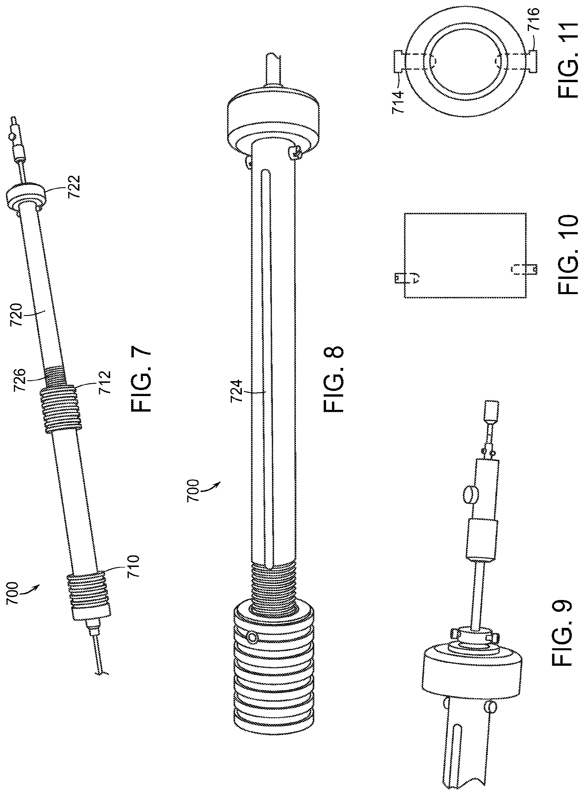
FIG. 7 is an alternative embodiment of the delivery system of the invention.
FIG. 8 is an alternative embodiment of the delivery system of the invention.
FIG. 9 is an alternative embodiment of the delivery system of the invention.
FIG. 10 is an embodiment for connecting an outer sheath handle to an inner screw that can be employed in the delivery systems of the invention. Screws (716) are offset to fall in the threads.
FIG. 11 is an embodiment for connecting an outer sheath handle to an inner screw that can be employed in the delivery systems of the invention.
FIG. 12 is an embodiment of the delivery system of the invention. The handle is turned (curved arrow) to retract sheath. The handle is held stationary while turning the handle to retract the sheath.
FIG. 13 is an embodiment of the delivery system of the invention. When threads are completely disengaged, the handle will lock into the slots and the bore spring and sealing spring will be exposed.
FIG. 14 is an embodiment of the delivery system of the invention. The sheath is retracted so the main body of the bifurcated graft is exposed by sliding the handle over the threaded engagement.
FIGS. 15A, 15B, 15C and 15D are embodiments of the delivery system of the invention. As shown in FIG. 15A, the apex clasp is released to deliver the bifurcated stent graft. The arrow depicts force.
FIG. 16 is another embodiment of the delivery system of the invention.
FIG. 17 is another embodiment of the delivery system of the invention.
FIG. 18 is another embodiment of the delivery system of the invention.
FIG. 19 is another embodiment of the delivery system of the invention.
FIG. 20 is another embodiment of the delivery system of the invention. The handle is turned (curved arrow) to retract the sheath. The handle is kept stationary while turning to retract the sheath.
FIG. 21 is another embodiment of the delivery system of the invention. Once the threads are completely disengaged the bare spring and sealing spring will be exposed and the turning of the handle will not retract the sheath back any further.
FIG. 22 is another embodiment of the delivery system of the invention. Pin and pull--retract the sheath so the main body of the graft is exposed by sliding the handle back over the lead screw handle.
FIG. 23 is another embodiment of the delivery system of the invention. The apex clasp is released.
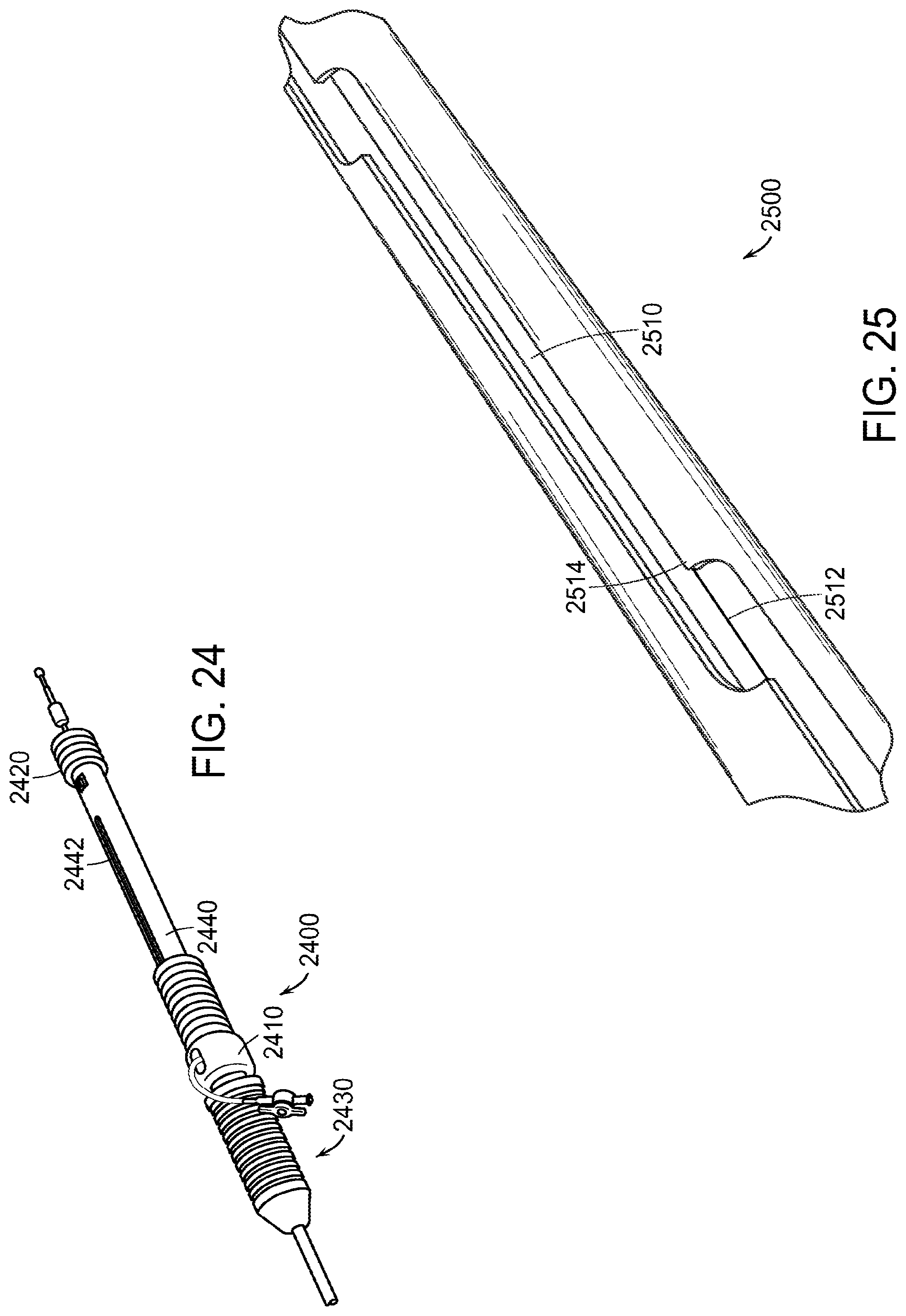
FIG. 24 is another embodiment of the delivery system of the invention.
FIG. 25 is another embodiment of the delivery system of the invention.
FIG. 26 is another embodiment of the delivery system of the invention.
FIG. 27 is another embodiment of the delivery system of the invention.
FIG. 28 is another embodiment of the delivery system of the invention.
FIG. 29 is another embodiment of the delivery system of the invention. Arrow indicates a distal end of an inner support member.
FIG. 30 is another embodiment of the delivery system of the invention. Arrow indicates proximal end of an inner support member.
FIG. 31 is another embodiment of the delivery system of the invention. Arrow indicates component to attach internal tube to distal handle grip.
FIG. 32 is another embodiment of the delivery system of the invention. Arrow indicates stop position indicator in locked position.
FIG. 33 is a further embodiment of the delivery system of the invention.
FIG. 34 is a further embodiment of the delivery system of the invention. Arrow indicates a side view of a lead screw.
FIG. 35 is a further embodiment of the delivery system of the invention. Arrow indicates an end view of a lead screw.
FIG. 36 is a further embodiment of the delivery system of the invention. Arrow indicates a lead screw rail.
FIG. 37 is a further embodiment of the delivery system of the invention.
FIG. 38 is a further embodiment of the delivery system of the invention.
FIG. 39 is a further embodiment of the delivery system of the invention.
FIG. 40 is a further embodiment of the delivery system of the invention that includes a distal clasp assembly (ASSY) and a loading mandrel (manufacture (MFG) aid).
FIG. 41 is a further embodiment of the delivery system of the invention.
FIG. 42 is a further embodiment of the delivery system of the invention.
FIG. 43 is a further embodiment of the delivery system of the invention.
FIG. 44 is a further embodiment of the delivery system of the invention.
FIG. 45 is a further embodiment of the delivery system of the invention.
FIG. 46 is a further embodiment of the delivery system of the invention.
FIG. 47 is a further embodiment of the delivery system of the invention.
FIG. 48 is a further embodiment of the delivery system of the invention.
FIG. 49 is a further embodiment of the delivery system of the invention.
FIG. 50 is a further embodiment of the delivery system of the invention.
FIG. 51 is a further embodiment of the delivery system of the invention.
FIG. 52 is a lead screw embodiment of the invention.
FIG. 53 is a lead screw embodiment of the invention.
FIG. 54 is a lead screw embodiment of the invention.
FIGS. 55A and 55B is another embodiment of the delivery system of the invention.
FIG. 56 is another embodiment of the delivery system of the invention.
FIGS. 57A, 57B, 57C, 57D, 57E and 57F are another embodiment of the delivery system of the invention (sheath valve assembly).
FIG. 58 is an embodiment of a distal tip of the delivery system of the invention.
FIG. 59 is an embodiment of a distal tip of the delivery system of the invention.
FIG. 60 is an embodiment of a distal tip of the delivery system of the invention.
FIG. 61 is an embodiment of a delivery system of the invention.
FIG. 62 is an embodiment of a delivery system of the invention.
FIG. 63 is an embodiment of a delivery system of the invention.
FIGS. 64A and 64B are embodiments of a delivery system of the invention.
FIG. 65 is an additional embodiment of the delivery system of the invention. An exemplary length of the sheath can be 84 cm.
FIG. 66 is an additional embodiment of the delivery system of the invention that includes a tip assembly (ASSY), support member assembly (ASSY) and a guidewire (GW) hypo-tube.
FIG. 67 is an additional embodiment of the delivery system of the invention that employs, for example, stainless steel and nylon.
FIG. 68 is an additional embodiment of the delivery system of the invention.
FIG. 69 is an additional embodiment of the delivery system of the invention.
FIGS. 70A, 70B and 70C are embodiments of a leg clasp system of the invention.
FIG. 71 is a representation of an abdominal aortic aneurysm.
FIGS. 72A, 72B and 72C are embodiments of a stent graft system of the invention. FIG. 72A is an example of placement of a stent graft system of the invention to treat an abdominal aortic aneurysm.
FIG. 73 is an embodiment of a stent of the invention.
FIG. 74 is an embodiment of a stent of the invention.
FIG. 75 is an embodiment of a stent of the invention.
FIGS. 76A and 76B are embodiments of a component of a delivery system of the invention.
FIG. 77 is an embodiment of an eyelet of a stent of the invention.
FIGS. 78A, 78B and 78C are embodiments of a telescoping stent grafts system of the invention.
FIGS. 79A, 79B and 79C are embodiments of a telescoping stent grafts system of the invention.
FIG. 80 is an embodiment of a stent of the invention.
FIG. 81 is a representation of an unexpanded stent of the invention.
FIG. 82 is a representation of an unexpanded stent of the invention.
FIG. 83 is a representation of an unexpanded stent of the invention.
FIG. 84 is a representation of an unexpanded stent of the invention.
FIG. 85 is a representation of an unexpanded stent of the invention.
FIGS. 86A, 86B, 86C, 86D and 86E are an embodiment of the apex capture device of the invention.
FIGS. 87A and 87B are embodiments of the apex capture device of the invention.
FIGS. 88A and 88B are embodiments of the apex capture device of the invention.
FIG. 89 is an embodiment of multiple stents of the invention.
FIG. 90 is an embodiment of multiple stents of the invention.
FIG. 91 is an embodiment of multiple stents of the invention.
FIG. 92 is an embodiment of multiple stents of the invention.
FIG. 93 is an embodiment of multiple stents of the invention.
FIG. 94 is an embodiment of multiple stents of the invention.
FIG. 95 is a representation of a modular component of a stent-graft system of the invention.
FIG. 96 is a representation of a modular component of a stent-graft system of the invention.
FIG. 97 is an embodiment of a stented graft of the invention.
FIG. 98 is an embodiment of a stented graft of the invention.
FIG. 99 is an embodiment of a stented graft of the invention.
FIG. 100 is an embodiment of a stented graft of the invention.
FIG. 101 is an embodiment of a stented graft of the invention.
FIG. 102 is an embodiment of a stented graft of the invention.
FIG. 103 is an embodiment of a stent of the invention.
FIG. 104 is an embodiment of a stent of the invention.
FIGS. 105A, 105B and 105C are embodiments of a stent of the invention.
FIG. 106 is an embodiment of a stent of the invention.
FIG. 107 is an embodiment of a barb of the invention.
FIG. 108 is an embodiment of a stent of the invention.
FIG. 109 is an embodiment of a stent graft of the invention.
FIG. 110 is an embodiment of a barb of the invention.
FIG. 111 is an embodiment of a barb of the invention.
FIG. 112 is an embodiment of a stent graft of the invention.
FIG. 113 is an embodiment of a stent graft of the invention.
FIG. 114 is a further embodiment of a component of the delivery system of the invention.
FIG. 115 is a further embodiment of a component of the delivery system of the invention.
FIG. 116 is a representation of a stent graft system of the invention as viewed following placement in a mock-silicon aorta.
FIG. 117 is an embodiment of a component of the delivery system of the invention.
FIG. 118 is an embodiment of a component of the delivery system of the invention.
FIG. 119 is an embodiment of a component of the delivery system of the invention.
FIG. 120 is an embodiment of a component of the delivery system of the invention.
FIG. 121 is an embodiment of a component of the delivery system of the invention.
FIG. 122 is an embodiment of a component of the delivery system of the invention.
FIG. 123 is an embodiment of a component of the delivery system of the invention.
FIG. 124 is an embodiment of a component of the delivery system of the invention.
FIG. 125 is representative of a leg clasp of the invention.
FIG. 126 is representative of a leg clasp of the invention.
FIGS. 127A, 127B, 127C and 127D are representative of a telescoping stent graft system of the invention.
FIG. 128 is an embodiment of the delivery system of the invention.
DETAILED DESCRIPTION OF THE INVENTION
The features and other details of the invention, either as steps of the invention or as combinations of parts of the invention, will now be more particularly described and pointed out in the claims. It will be understood that the particular embodiments of the invention are shown by way of illustration and not as limitations of the invention. The principle features of this invention can be employed in various embodiments without departing from the scope of the invention.
In an embodiment, represented by FIGS. 1 through 57 as an example, the invention is a stent graft delivery system 5500, comprising a handle that includes distal grip 5530 and handle body 5540 extending from one end of distal grip 5530, the handle defining conduit and track 5542 along a portion of the length of distal grip 5530 and handle body 5540; an internal lead screw assembly 5510 within the conduit, the internal lead screw assembly 5510 being moveable along a major axis of the conduit, and including a threaded portion 5512 that extends through the track 5542; a lead screw nut 5520 that extends about the handle body 5540 and threadably engaged with the threaded portion 5512 of the internal lead screw assembly 5510, whereby rotation of the lead screw nut 5520 while abutting the distal grip 5530 causes movement of the internal lead screw assembly 5510 relative to the handle and wherein the lead screw nut 5520 simultaneously is slidable along the handle body 5540 while engaged with the internal lead screw assembly 5510, thereby providing at least two mechanisms for causing movement of the internal lead screw assembly 5510 relative to the handle.
Referring to FIG. 57A, the stent graft delivery system can further include a support member 5740 fixed to the handle body, and an outer sheath 5550 extending about a portion of the support member 5740 and fixed, either directly or through slider 5700, to the internal lead screw assembly 5510, whereby relative movement of the handle body 5540 and the internal lead screw assembly 5510 causes relative movement of the support member 5740 and the outer sheath 5550.
The internal lead screw assembly 5510 of the stent graft delivery system 5500 of the invention can define an opening essentially coaxial with the handle, wherein the support member extends through the internal lead screw assembly, as shown in FIG. 55A.
As can be seen in the inset of FIG. 57A, support member 5740 includes a hypo-tube 5742 and a support tube 5744 within the hypo-tube 5742. Hypo-tube 5742 typically is formed of stainless steel, while support tube 5744 typically is formed of nylon, such as VESTAMID.RTM.. Hypo-tube 5742 is fixed to the handle body, such as at proximal end cap 5544, as shown in FIG. 56 (also shown as proximal end cap 3350 in FIG. 33). Also shown in the inset to FIG. 57A, but not part of support member 5740, are elongate member 8614, which is connected to distal apex capture portion 8610, and catheter 8613, which is connected to proximal apex capture portion 8600a, all of which are shown in FIG. 86D.
The stent graft delivery system of the invention can further include a slider 5700. The slider 5700 of the stent graft delivery system comprises a slider body 5720 defining a central orifice through which the support member 5740 extends and a flush valve orifice 5712 extending substantially normal to the central orifice, the slider body 5720 being detachably fixable to the internal lead screw assembly 5510 (FIG. 55A by suitable means, such as, for example, release pin 6210, which extends through internal lead screw assembly into slider, as shown in FIGS. 62 and 63); a slider cap 5710 coupled to a distal end of the slider body 5720, the slider cap 5710 defining a central orifice that is substantially aligned with the central orifice of the slider body 5720 and through which the support member 5740 extends; a sheath valve knob 5790 threadably coupled to slider body 5720, an outer sheath 5550 extending from a distal end of the slider cap 5710, the outer sheath 5550 defining a catheter that is substantially aligned with the central opening of the slider body 5720 and through which the support member 5740 extends; a wiper valve 5750 at the central opening of the slider body proximal to the flush valve orifice 5712, the wiper valve 5750 forming a seal about the support member; an x-valve assembly 5760 at the central opening of the slider body proximal to the wiper valve 5750, the x-valve assembly 5760 forming a seal about a guidewire within support tube 5744 upon withdrawal of the support member from the slider body 5720; and a sheath valve 5770 at the central opening of the slider body 5720 and proximal to the x-valve assembly 5760, the sheath valve 5770 being operable by activation of sheath valve knob 5790 to seal the central opening.
In an embodiment, the x-valve assembly 5760 includes a nitinol gasket as shown in FIGS. 57B through 57F.
"Proximal" means, when reference is made to a delivery system or a component of a delivery system, such as an apex capture device, a slider for a stent graft delivery system or a leg clasp, closest to the clinician using device. Likewise, "distal" means, when reference is made to a delivery system or a component of a delivery system, such as an apex capture device, a slider for a stent graft delivery system or a leg clasp, away from the clinician using the device.
When reference is made to a "stent" or a "stent graft system," "proximal" means that end of the stent or stent graft system that is towards the head of the patient and "distal" means that end of the stent or stent graft system that is away from the head of the patient.
In another embodiment, the invention is a slider 5700 for a stent graft delivery system, the slider 5700 comprising a slider body 5720 defining a central orifice through which a support member 5740 extends and a flush valve orifice 5712 extending substantially normal to the central orifice, the slider body 5720 being detachably fixable to an internal lead screw assembly 5510 (FIGS. 55A, 55B and 56); a slider cap 5710 (FIG. 57A) coupled to a distal end of the slider body, the slider cap 5710 defining a central orifice that is substantially aligned with the central orifice of the slider body 5720 and through which the support member extends; a sheath valve knob 5790 threadably coupled to slider body 5720, an outer sheath 5550 extending from a distal end of the slider cap 5710, the outer sheath 5550 defining a lumen that is substantially aligned with the central opening of the slider body 5720 and through which the support member 5740 extends; a wiper valve 5750 at the central opening of the slider body 5720 proximal to the flush valve orifice 5712, the wiper valve 5750 forming a seal about the support member 5740; an x-valve assembly 5760 at the central opening of the slider body 5720 proximal to the wiper valve 5750, the x-valve assembly 5760 forming a seal about a guidewire within support tube 5744 upon withdrawal of the support member 5740 from the slider body 5720; and a sheath valve 5770 at the central opening of the slider body 5720 and proximal to the x-valve assembly 5760, the sheath valve 5770 being operable by activation of the sheath valve knob 5790 to seal the central opening.
FIGS. 61-64B are embodiments of a delivery system of the invention.
Referring now to FIGS. 1 to 3, an exemplary embodiment of an improved pin-and-pull delivery system 100 according to the present invention is shown. The pin-and-pull delivery system 100 provides an inner catheter 110 that is slidably disposed within an outer sheath control catheter 120. This configuration of the catheter 110, 120 can also be referred to as a telescopic assembly. The outer sheath control catheter 120 is longitudinally and rotationally fixed to a sheath 130 that is used to house the non-illustrated stent graft.
In an exemplary embodiment, the outer sheath control catheter 120 is an aluminum tube attached to a sheath hub 140, which is attached to the sheath 130. The inner catheter 110 is polycarbonate tube having a longitudinally cut slot 310 (e.g., see FIG. 3). The inner catheter 110 is longitudinally and rotationally fixed to a pushrod 150 (e.g., a stainless steel hypo-tube). By attaching the outer sheath control catheter 120 to the sheath hub 140, the inner catheter 110 can be retracted into the outer sheath control catheter 120 and will maintain rotational alignment of the catheters 110, 120 by the presence of a setscrew 320 engaged in the slot 310. The groove and set-screw configuration will prevent the sheath 130 from rotating when the stent graft is deployed, which movement undesirably twists the prosthesis from a desired implantation position. This device is beneficial when used with a detachable sheath because the hemostasis 160, over the push rod 150, is in front of the catheters 110, 120.
FIGS. 4 to 6 illustrate how the delivery system of FIGS. 1 to 3 can be used to implant a bifurcated stent graft. When the compressed bifurcated stent graft 410 is positioned at a target site, the delivery system is pinned with respect to the patient. The outer sheath control catheter 120 is drawn proximally from the position shown in FIG. 4 to the position shown in FIG. 5. With the outer sheath control catheter 120 in the fully retracted position (FIG. 5), the stent graft 410 is almost completely deployed in the patient's vessel. The only remaining control of the stent graft 410 is the releasable grasping of bare stent apices 412 by the apex capture device 510 of the delivery system. Control of the apex capture device 510 occurs from the proximal-most end of the pushrod 150. One exemplary embodiment of the apex capture device 510 and its control assembly is disclosed in the family of applications beginning with U.S. Provisional Patent Application Ser. No. 60,499/652, filed Sep. 3, 2003, and U.S. patent application Ser. No. 10/784,462, filed Feb. 23, 2004, which applications and the entire family thereof is hereby incorporated by reference herein in its entirety. In such an embodiment, a non-illustrated control rod internal to the pushrod 150 is moved relative (arrow A in FIG. 6) to the pushrod 150 to separate the tines grasping one or more of the exposed bare stent apices 412 from control surfaces. This movement creates a gap therebetween to free the bare stent apices 412 from their controlled capture.
An alternative embodiment to that illustrated in FIGS. 5 and 6 is shown in FIGS. 7 to 9. This delivery system 700 improves the control and accuracy of deployment of the stent graft by adding mechanical advantage to the retraction of the introducer outer sheath. Mechanical advantage allows for a "smooth" retraction of the outer sheath by not allowing the build up of potential energy, stored in the compressed stent graft, to cause an unexpected jumping or jerking motion during outer sheath retraction. More specifically, the delivery system 700 has two interconnecting parts: a hollow outer sheath handle 710 and an inner screw handle 720. The proximal end of the outer sheath handle 710 has an interior cavity for receiving therein the distal end of the inner screw handle 720.
One exemplary embodiment for connecting the outer sheath handle 710 to the inner screw handle 720 is illustrated in FIGS. 10 and 11. A thread engagement portion 712 of the outer sheath handle 710 has two opposing threaded engagement devices 714, 716 longitudinally offset from one another as illustrated in FIG. 10. One of the threaded engagement devices 714 can be, for example, a ball screw, and the other threaded engagement device 716 can be a set screw. The inner surface of the hollow outer sheath handle 710 is smooth in this particular embodiment. Engagement of the outer sheath handle 710 to the threads 726 of the inner screw handle 720 is made by having the threaded engagement devices 714, 716 ride in the threads of the inner screw handle 720. Thus, turning of the inner screw handle 720 causes the outer sheath handle 710 to retract over or extend from the distal end of the inner screw handle 720 in a controlled fashion. Turning can be assisted with a proximal turn knob 722 rotationally fixed to the inner screw handle 720.
Threads 726 extends for a longitudinal length that is greater than the amount that is necessary to overcome the greatest force required for stent graft deployment. Once that greatest point of force is overcome, the chance of handle jerk or slippage decreases and, therefore, the two handle portions 710, 720 can be moved longitudinally freely with respect to one another. To achieve the transition from longitudinal controlled and slow movement to longitudinal free movement (and speedy if desired), at the proximal end of the threads of the inner screw handle 720, screw channels 724 can be cut into the handle body to allow the threaded engagement device 716 to fall into one of the screw channels 724 and the threaded engagement device 714 to fall into the other channel (not illustrated) on the opposite side of the inner screw handle 720. A threaded engagement device 714 can be, for example, a ball screw, which would be desirable in this configuration because it can be used to center the threads against the relatively harder threaded engagement device 716, such as a set screw. Changing the force the threaded engagement devices 714, 716 impart against the threads can be accomplished by adjusting the tension on a ball of the ball set screw or by decreasing the depth of a set screw into the handle 710.
Functioning of the delivery system 700 is illustrated, for example, in the diagrams of FIGS. 12, 13, 14, 15A, 15B, 15C and 15D. Before the inner screw handle 720 is turned to retract the outer sheath handle 710, the outer sheath catheter 1210 completely covers the stent graft 1220, which is loaded therein just behind (proximal of) the nose cone 1230. The turn knob 722 is rotated to move the outer sheath handle 710 proximally and begin to deploy the stent graft 1220 from the outer sheath catheter 1210. The user holds the inner screw handle 720 longitudinally stationary while turning so that the outer sheath catheter 1210 moves proximally. This step is shown in FIG. 13. Once the threads 726 (FIG. 12) are completely disengaged from the thread engagement portion 712 of the outer sheath handle 710, the outer sheath handle 710 will rotationally lock into the screw channels 724 while still being longitudinally free to move with respect to the inner screw handle 720. At this point, the bare stent 1310 and the first sealing stent 1320 are exposed. After channel lock occurs, the proximal end of the stent graft 1220 is exposed from the outer sheath catheter 1210 as shown in FIG. 13. With the opposing threaded engagement devices 714, 716 (FIG. 11) locked into the screw channels 724 (FIG. 12), the outer sheath handle 710 can no longer rotate with respect to the inner screw handle 720 and, now, can be moved proximally as desired by the user. Accordingly, the outer sheath catheter 1210 can be retracted so that the entire body of the stent graft 1220 is exposed as shown in FIG. 14. At this point, the outer sheath handle 710 is positioned over the inner screw handle 720 and up to the turn knob 722 and the stent graft 1220 is only held to the delivery system 700 by the apex clasp device 1410. With release of the apex clasp device 1410, the stent graft 1220 is released from the delivery system 700 and, thereafter, the delivery system 700 can be removed from the patient without impacting the implantation of the stent graft 1220.
The delivery system 700 of FIGS. 12, 13, 14, 15A, 15B, 15C and 15D can be loaded with a 28 mm.times.150 mm graft into a 19.5 French OD braided introducer sheath, for example. In this configuration, the delivery system can deploy the bifurcated stent graft 1220 utilizing the mechanical advantage applied by the screw mechanism to release the first section of the graft (bare stent 1310 and first sealing stent 1320). The remainder of the stent graft can, then, be deployed by the pin-and-pull assembly of the device after the threads 726 are disengaged. This configuration eliminates any requirement to have the physician actively disengage the threads.
Benefits achieved by the telescopic configurations shown in FIGS. 1 to 15 are illustrated with regard to FIGS. 15A, 15B, 15C and 15D. The pin-and-pull systems of the prior art experienced an undesired force to the inner stabilizing member during deployment because there is a tendency to flex where gripped thereon (FIGS. 15A, 15B, 15C and 15D). This flexing caused misalignment of the sheath hub and the inner stabilizing member, which, in turn, required the physician to increase deployment forces for retracting the outer sheath, thus, correspondingly increasing the force against the inner stabilizing member (a damaging cycle).
An alternative to the two-part controlled deployment of FIGS. 7, 8, 9, 10, 11, 12, 13, 14, 15A, 15B, 15C and 15D for connecting the outer sheath handle 710 to the inner screw handle 720 is illustrated in FIGS. 16 to 23. These figures illustrate a delivery system 1600 that aids in the controlled, accurate deployment of a stent graft. This configuration adds mechanical advantage to the retraction of the introducer sheath, which allows for a "smooth" retraction of the outer sheath by not permitting the build up of potential energy, stored in the compressed stent graft, to cause an unexpected jumping or jerking motion during outer sheath retraction.
A distal engagement portion 1612 of the outer sheath handle 1610 has an internally threaded bore for receiving therein a threaded portion 1622 of the inner screw handle 1620. In an exemplary embodiment, the distal engagement portion 1612 is made of DELRIN.RTM.. Engagement of the outer sheath handle 1610 to the inner screw handle 720 (FIG. 7) is made by turning the outer sheath handle 1610 with respect to the inner screw handle 1620. This causes the outer sheath handle 1610 to retract over or extend from the distal end of the inner screw handle 1620 in a controlled fashion. Turning can be assisted with a proximal turn knob 1624 rotationally fixed to the inner screw handle 1620.
The threaded portion 1622 extends for a longitudinal length that is greater than the amount that is necessary to overcome greatest force required for stent graft deployment. Once that greatest point of force is overcome, the chance of handle jerk or slippage decreases and, therefore, the two handle portions 1610, 1620 can be moved longitudinally freely with respect to one another. To achieve the transition from longitudinal controlled and slow movement to longitudinal free movement (and speedy if desired), at the proximal end of the threads of the inner screw handle 1620, a channel 1626 (or more channels, e.g., two opposing channels) can be cut into the inner screw handle 1620. A non-illustrated set screw is located at the distal engagement portion 1612 to protrude into the interior and engage the threaded portion 1622. When the two handle portions 1610, 1620 are rotated sufficiently far to move the interiorly projecting set screw proximal of the threaded portion 1622, the set screw will ride directly into the channel 1626 (or the set screws directly into the channels 1626). A set screw is desirable in this configuration because it can be used to increase and decrease tension for rotating the two handle portions 1610, 1620 with respect to one another. Changing the force imparted against the threaded portion 1622 can be accomplished by decreasing/increasing the depth of the set screw into the distal engagement portion 1612.
Functioning of the delivery system 1600 is illustrated, for example, in the diagrams of FIGS. 20 to 23. Before the inner screw handle 1620 is turned to retract the outer sheath handle 1610, the outer sheath catheter 2010 completely covers the stent graft 2020, which is loaded therein just behind (proximal of) the nose cone 2030. The turn knob 1624 is rotated to move the outer sheath handle 1610 proximally and begin to deploy the stent graft 2020 from the outer sheath catheter 2010. The user holds the inner screw handle 1620 longitudinally stationary while turning so that the outer sheath catheter 2010 moves proximally. An embodiment of the step is shown in FIG. 21. Once the channels 1626 are completely disengaged from distal engagement portion 1612 of the outer sheath handle 1610, the outer sheath handle 1610 will rotationally lock into the channel(s) 1626 while still being longitudinally free to move with respect to the inner screw handle 1620. At this point, the bare stent 2110 and the first sealing stent 2120 are exposed. After channel lock occurs, the proximal end of the stent graft 2020 is exposed from the outer sheath catheter 2010 as shown in FIG. 21. With the set screw(s) locked into the channel(s) 1624, the outer sheath handle 1610 can no longer rotate with respect to the inner screw handle 1620 and, now, can be moved proximally as desired by the user. Accordingly, the outer sheath catheter 2010 can be retracted so that the entire body of the stent graft 2020 is exposed as shown in FIG. 22. At this point, the outer sheath handle 1610 is positioned over the inner screw handle 1620 and up to the turn knob 1624 and the stent graft 2020 is only held to the delivery system 1600 by the apex clasp device 2210. With release of the apex clasp device 2210, the stent graft 2020 is freed from the delivery system 1600 and, thereafter, the delivery system 1600 can be removed from the patient without impacting the implantation of the stent graft 2020.
The delivery system 1600 of FIGS. 16 to 23 can be loaded with a 28 mm.times.150 mm graft into a 19.5 French OD braided introducer sheath, for example. In this configuration, the delivery system 1600 can deploy the bifurcated stent graft 2020 utilizing the mechanical advantage applied by the screw mechanism to release the first section of the graft (bare stent 2110 and sealing stent 2120). The remainder of the stent graft 2020 can, then, be deployed by the pin-and-pull assembly of the device after the channels 1626 are disengaged. This configuration eliminates any requirement to have the physician actively disengage the threads.
A further alternative to the two- or multi-part controlled deployment of FIGS. 7 through 23 is illustrated in FIGS. 24 through 32. In general, these figures describe a "jogged slot" handle that aids in the controlled, accurate deployment of a stent graft. As set forth above, handles to be used on the delivery system of an AAA device need to gain better control over placement accuracy and/or to better fixate the AAA graft during graft placement. The present invention provides a "jogged slot" (which can be configured in a similar manner as an automatic transmission shifter slot (i.e., stair steps)) to improve placement accuracy. The "jogged slot" in this example utilizes stent graft delivery system features described in the family of applications beginning with U.S. Provisional Patent Application Ser. No. 60,499/652, filed Sep. 3, 2003, and U.S. patent application Ser. No. 10/784,462, filed Feb. 23, 2004, incorporated herein and including a slotted aluminum handle body, a distal handle grip, a proximal handle grip and the proximal clasp assembly. The invention, however, is not limited to this particular embodiment. If desired, the actuation knob can be replaced with an end cap that serves to fixate the internal hypotube.
As shown in FIGS. 24 and 25, the internal mechanism of the delivery system 2400 includes an internal tube 2500 with a jogged slot 2510 in which the slider assembly 2600 (FIG. 26) can slide from the distal portion of the delivery system 2400 (shown in FIG. 24) to the proximal portion of the delivery system 2400 during stent graft deployment. During deployment of the stent graft, the delivery system 2400 with the jogged slot 2510 only permits the handle parts to move to a particular extent that is less than the total movement required for complete deployment of the stent graft. The jog 2512 or "Z" in the slot 2510 has a circumferential or transverse portion 2514 preventing the proximal handle grip 2410 from moving all the way back to the end cap 2420 without first having to be rotated circumferentially/transversely around the jog 2512. FIGS. 26 and 27 show that the slider assembly 2600 can be, in an exemplary embodiment, a cylindrical hub with a barbed fitting at its distal end to receive the outer stent sheath 2610. At the proximal end of the slider assembly 2600 is an o-ring through which the support member hypotube passes. The slider assembly 2600 serves as both an attachment point for the outer stent sheath 2610 to the handle and as a hemostasis port for flushing of the sheath catheter. Exiting from the side of the slider assembly 2600 is a "boss" 2700 that extends outward, through the slot 2442 in the handle body 2440, and attaches to the proximal handle grip 2410. The flush port runs through this boss 2700 and attaches to the flush port tubing and valve 2710.
FIGS. 28 to 30 illustrate the attachment of the slider assembly 2600 to the proximal handle grip 2410, which attachment allows actuation of the delivery system 2400 and deployment of the stent graft from the outer stent sheath 2610. The outer stent sheath 2610, which is attached to the slider assembly 2600, is retracted in a proximal sliding motion (indicated by arrows A in FIG. 28) over the stent graft. More specifically, in this exemplary embodiment, the distal handle 2430 is held stationary while the proximal handle grip 2410 is moved back (proximally) to deploy the stent graft. The internal support member that is located coaxially within the outer stent sheath 2610 (see FIGS. 29 and 30) serves as a platform or anchor to prevent the stent graft from retracting along with the outer stent sheath 2610.
Significantly, the internal tube 2500 of the delivery system 2400 provides advantages to permit controlled deployment (unsheathing) of the stent graft. The internal tube 2500 in this exemplary embodiment is made from polycarbonate material and is sized so that it can move freely within the slotted aluminum handle body 2440. The slider assembly 2600 is sized so that it can move freely within the internal tube 2500. The internal tube 2500 has a straight tube running the full length of the delivery system 2400. Machined through the wall of the internal tube 2500 is the slot 2510 which is "jogged" in the manner of an automobile transmission shifter. As such, the circumferential or transverse portion 2514 of the jogged slot 2510 provides a so-called stop (or stops) that control deployment of the stent graft at different points during the stent graft deployment sequence. The jog(s) 2512 that is/are cut into the internal tube 2500 only allows the slider assembly 2600 to move within that particular jog segment of the internal tube 2500. Further retraction of the outer stent sheath 2610 requires the user to actively turn the end cap 2420 to a next setting, thus allowing further proximal movement of the slider assembly 2600. The boss 2700 of the slider assembly extends through the jogged slot 2510 of the internal tube 2500 and through the slot 2442 of the handle body 2440. The boss 2700 is, then, connected to the proximal handle grip 2410. The internal tube 2500 is attached at the distal end of the delivery system 2400 to the distal handle 2430. Rotation of the distal handle 2430 allows rotation of the internal tube 2500 within the handle body 2440.
FIGS. 31 and 32 show one exemplary embodiment for indicating a position of the internal tube 2500 in the various stop positions. The indicator can be realized through either a viewing window 3200 with numbers/letters or by color coded dots. From the package in which the system is delivered, the delivery system 2400 can be in a locked position (indicated, for example, with an "L") of the jogged slot 2510. In this orientation, the clinician could remove the delivery system 2400 from the package and perform flushing procedures without a concern of prematurely deploying the stent graft during handling. The clinician keeps the delivery system 2400 in the locked position/state during insertion of the device into the patient's artery and while tracking to the site of stent graft deployment. The stop mechanism prevents any possibility of inadvertent proximal movement of the outer stent sheath 2610, which could partially deploy the stent graft.
Once the clinician identifies the deployment site and is ready to deploy the stent graft, he/she turns the distal handle 2430 until, for example, stop position 1 is obtained. With the device in stop position 1, the jogged slot 2510 of the internal tube 2500 and the slot 2442 of the handle body 2440 will be aligned, thus allowing the proximal handle grip 2410 to be slid proximally to allow partial stent graft deployment. Positioning of the next exemplary jog or stop on the internal tube 2500 is set so that the supra-renal struts and at least two stent graft springs (i.e., stents) are deployed from the outer stent sheath 2610. With the stent graft partially deployed, but with the suprarenal struts (i.e., of the bare stent) still captured in the distal clasp mechanism, the stent graft can still be maneuvered proximally or distally within the aorta to establish sealing site positioning.
At this point, the clinician can fix the delivery system 2400 relative to the patient to maintain the stent graft position relative to the aorta. Then, the clinician can move the distal handle 2430 to stop position 2 and continue to move the proximal handle grip 2410 in a proximal direction until, for example, the contralateral leg of a bifurcated stent graft is released from the outer stent sheath 2610. The stop on the delivery system 2400 at the end of stop position 2 can, in an exemplary embodiment, prevent the ipsilateral leg from deploying from the outer stent sheath 2610. Then, the clinician can rotate the delivery system 2400 to orient the stent graft's contralateral leg to align with the patient's arterial anatomy. Once the stent graft is oriented properly, the clinician can actuate the distal clasp assembly and release the suprarenal struts. The captured ipsilateral leg, along with the anchored supra-renal strut and proximal seal serve as fixation during crossing of the guidewire into the contralateral leg and subsequent placement of the contralateral leg graft placement. Once contralateral leg graft placement is achieved, the delivery system 2400 is moved to stop position 3 and the proximal handle grip 2410 is pushed proximally to fully release the stent graft. The particular placement/configuration of the stop positions is determined based upon various factors, including the size of the prosthesis and the features of the vessel in which the prosthesis is to be placed.
Yet another alternative to the multi-step controlled deployment of FIGS. 7 to 32 is illustrated in FIGS. 33 to 51. These figures describe, in general, an internal lead screw handle that aids in the controlled, accurate deployment of a stent graft. As indicated above, it is desirable to gain better control over placement accuracy of an AAA graft during stent graft placement with an AAA delivery system. The internal lead screw embodiment described herein increases placement accuracy by allowing the operator to have more control over the initial deployment of the stent graft.
An exemplary embodiment of a delivery system 3300 with an internal lead screw that deploys a stent graft from a sheath is shown beginning with FIG. 33 and ending with FIG. 51. The delivery system 3300 has an internal lead screw 3310 (see FIGS. 34, 35, 37), a lead screw nut 3320 (see FIGS. 35 and 37), a lead screw rail 3330 (see FIGS. 36 and 37), a distal handle grip 3340, a flush port and a proximal end cap 3350. This configuration utilizes a support member 3360 with a hypotube at its proximal end and a distal clasp assembly similar to the stent graft delivery system described in the patent family previously incorporated herein by reference. The lead screw nut 3320 can be actuated in different ways to deploy the stent graft from the outer sheath 3370. One exemplary actuation rotates the lead screw nut slowly to pull back on the outer sheath 3370 using the threads of the internal lead screw 3310. Another exemplary actuation simply pulls back on the lead screw nut 3320 to deploy the stent graft. By housing the internal lead screw 3310 (which is formed, in this example, from cutting material on outer portions of a round threaded screw to a rectangular cross-section with threads on only one side, i.e., a partial lead screw) within the lead screw rail 3330, the system can bypass the need to always use the first exemplary actuation process.
The support member 3360 is coaxially contained within the delivery system 3300. The support member 3360 is attached at its proximal end to the proximal end cap 3350 of the delivery system 3300. The support member 3360 travels coaxially through the internal lead screw 3310, the flush port, and the outer sheath 3370. At the distal end of the support member 3360 is a capture pod that holds the proximal (caudal) end of the stent graft. A guidewire catheter and the distal clasp assembly tubing (FIG. 39) travel coaxially within the support member 3360 along the full length of the delivery system 3300. Contained within the distal end of the outer sheath 3370 can be the crimped stent graft and the distal clasp assembly. The distal clasp assembly terminates at the distal end with a flexible tip 4100, shown in FIG. 41.
The internal lead screw 3310 (FIG. 33) used in this exemplary embodiment can be made from a 1-inch diameter lead screw with a 0.400 inch linear lead per rotation of the lead screw nut. The internal lead screw 3310 is approximately 14 cm in length and is machined so that most of the threads are cut away from the circumference. Machining of the internal lead screw 3310 is performed to allow the internal lead screw 3310 to fit in the lead screw rail 3330 and to allow the lead screw rail 3330 to fit between the internal lead screw 3310 and the lead screw nut 3320. The lead screw rail 3330 acts to center the lead screw nut 3320 on the partial internal lead screw 3310. The diameter of the lead screw rail 3330 is approximately equivalent to the minor diameter of the lead screw nut 3320. By locating the lead screw rail 3330 in this configuration, the internal lead screw 3310 can slide within the groove 3530 of the lead screw rail 3330 (FIG. 35).
Attached to the distal end of the internal lead screw 3310 is a flush port (FIG. 38). An O-ring is contained in the proximal end of the flush port, which seals around the support member hypotube. At the distal end of the flush port is a nipple that attaches to the outer sheath 3370.
During assembly of the delivery system 3300 (shown, in part, in FIGS. 39 to 41), the stent graft is first loaded into the outer sheath 3370 along with the distal clasp assembly and the guidewire catheter. Then, the flexible tip 4100 is threaded onto the distal clasp assembly. As shown in FIGS. 42 and 43, the pre-assembled support member 3360 is then loaded into the outer sheath 3370. Then, the support member 3360 is guided through the flush port and the internal lead screw 3310. The outer sheath 3370 is, then, attached to the flush port and is clamped (see FIG. 38). As shown in FIG. 44, the handle body is assembled by first attaching the distal handle grip 3340 to the lead screw rail 3330. Then, as shown in FIGS. 45 to 46, the sub-assembly of the outer sheath 3370/flush port/internal lead screw 3310 is threaded through the opening in the front of the distal handle grip 3340 and the internal lead screw 3310 is set in the groove 3530 of the lead screw rail 3330. FIGS. 47 to 48 show that the lead screw nut 3320 is passed over the lead screw rail 3330 and mated with the internal lead screw 3310. The outer sheath 3370 is moved forward and the lead screw nut 3320 is threaded forward until it contacts the distal handle grip 3340. As illustrated in FIGS. 49 to 51, the proximal end cap 3350 is, then, placed over the support member 3360 and attached to the lead screw rail 3330. The support member 3360 is secured to the proximal end cap 3350 and the distal clasp mechanism hardware is installed.
In use, the clinician first flushes the delivery system 3300 by forcing saline through the flush port. The saline fills the annular space between the outer sheath 3370 and the support member 3360, permeates through the crimped stent graft, and exits between the outer sheath 3370 and the flexible tip 4100. The o-ring in the flush port seals the hypotube of the support member 3360 and prevents leakage through the delivery system 3300. Then, the clinician feeds the delivery system 3300 over an indwelling guidewire and tracks the device to the stent graft deployment site.
At this point, the clinician has the option to either slowly release the stent graft by rotating the lead screw nut 3320 or rapidly release the stent graft by pulling back on lead screw nut 3320 and, thereby, sliding the internal lead screw 3310 down the lead screw rail 3330. At some point in the deployment of the stent graft, the release can be stopped to actuate the distal clasp assembly and release the leading struts (bare stent) of the stent graft. Because the stent graft is usually severely constrained within the outer sheath 3370, deployment forces with AAA devices can be quite high.
The internal lead screw of the invention has the advantage of incorporating a screw system to convert the linear force to a torque force. The torque force that the clinician must exert on the lead screw nut to deploy the stent graft is ergonomically less difficult than the linear pull force. In addition to the mechanical advantage obtained with the lead screw nut, the screw type mechanism allows for greater control in the release of the stent graft. In a linear pin-and-pull system, the largest force to deploy the stent graft is at the initial release of friction between the stent graft and the sheath. As soon as that initial friction is overcome, the deployment force quickly declines. From an ergonomic point of view, it is very difficult for a clinician to maintain control and speed of the deployment at the moment when the frictional forces are overcome. It is very common for the stent graft to be un-sheathed more than was desired due to this loss of control. A screw type mechanism according to the present exemplary embodiment allows the clinician to have more control over this initial release of the stent graft, which is a critical factor for stent placement accuracy.
FIGS. 52 to 54 illustrate an improvement to the lead screw embodiment of the previous figures. In the above embodiment, the user was required to grip and turn the handle knob with one hand while holding the sheath handle grip with the other hand. See FIG. 52. Actuation of this handle required the user to concentrate on two motions at once for deployment of the stent graft. Also, there was a possibility of turning the hypotube/inner member out of alignment with the sheath hub, which misalignment could decrease stent graft placement accuracy. Therefore, a second handle 5300 was added behind (proximal) the turn knob 5310 (FIGS. 53 and 54). The second handle 5300 is attached to the bearing engagement that is affixed to the inner member 5360 (hypotube). The user grips the second handle 5300 and turns the lead screw knob with the thumb and pointer finger. Now, the user's hand is pinned in one location as the knob is turned and the sheath handle is retracted back over the lead screw.
FIGS. 55A through 57 illustrate another exemplary embodiment of the delivery systems of the present invention. This example of the delivery system 5500 includes features of the pin-and-pull telescopic systems 100, 700, 1600, 2400 and the delivery system 3300. The delivery system 5500 has an internal lead screw 5510, a lead screw nut 5520, a hollow distal grip handle (also referred to herein as "distal grip") 5530, and a hollow interior body 5540 (also referred to herein as "handle body"). The internal lead screw (also referred to herein as "internal lead screw assembly") 5510 rides within a track 5542 of the hollow interior body 5540. The lead screw nut 5520 has a non-illustrated interior thread having a pitch corresponding to upper thread portions (also referred to herein as "threaded portion") 5512 to cause longitudinal movement of the internal lead screw 5510 when rotated about the hollow interior body 5540. Thus, the lead screw nut 5520 is rotatably freely mounted about the hollow interior body 5540. The lead screw nut 5520 is also longitudinally freely mounted about the hollow interior body (also referred to herein as "handle body") 5540. In this configuration, the clinician has the ability to rotate the lead screw nut 5520 to any desired retraction of the internal lead screw 5510. At any time before, during, or after such rotation, the clinician can move the lead screw nut 5520 longitudinally proximal, taking the internal lead screw 5510 along with it at the same speed of proximal movement of the lead screw nut 5520. The internal lead screw 5510 is longitudinally fixed to the outer sheath 5550, which is longitudinally free from the hollow distal grip handle 5530 and the hollow interior body 5540. In this manner, rotation of the lead screw nut 5520 moves the outer sheath 5550 relatively slowly (dependent upon the pitch of the upper thread portion 5512), and longitudinal movement of the lead screw nut 5520 moves the outer sheath 5550 relatively fast.
The difference between FIGS. 55A and 56 illustrates the relative positions of the internal lead screw 5510, the hollow distal grip handle 5530, the hollow interior body 5540, and the outer sheath 5550 after the lead screw nut 5520 has been moved proximally to (about) its proximal-most position. In FIG. 55A, the outer sheath 5550 surrounds the push rod 5560 and completely covers the cavity within the outer sheath 5550 in which the non-illustrated stent graft is stored (compressed) prior to implantation. The outer sheath 5550 extends all the way to touch the nose cone 5570 and form a seal therewith to reliably secure the stent graft therein. In FIG. 56, in comparison, the outer sheath 5550 can be seen completely retracted from the nose cone 5570 to clear the indented boss 7000 at the distal end of the push rod 5560. The apex capture assembly 5568 for removably securing the bare stent (e.g., 2310) of the stent graft is shown just proximal of the nose cone 5570 and in the closed (secured) position of the apex capture assembly 5568. Actuation of the apex release device 5580 moves the inner catheter 5590 connected to the proximal apex capture portion 5572 (with its bare-stent-capturing tines) proximally to create a space through which the individual proximal apices of the bare stent can escape.
It is noted that the entire device disposed in the interior of the hollow distal grip handle 5530 shown in FIG. 55A is not shown in FIG. 56. This device, slider 5700, is shown, in enlarged detail, in FIG. 57A. From distal to proximal, the outer sheath 5550 is secured by a sheath clip 5702 to a distal nipple of a slider cap 5710. The slider cap 5710 has a check or flush valve (also referred to herein as "flush valve orifice") 5712 fluidically connecting the inner chamber of the slider cap 5710 to the environment outside the flush valve orifice 5712. An intermediate slider body assembly (also referred to herein as "slider body") 5720 is secured to the slider cap 5710 with an o-ring 5730 therebetween to keep the respective interior chamber fluidically connected to one another and fluidically sealed from the environment outside the two parts slider cap 5710, and slider body assembly 5720.
A release 5514 (e.g., a thumbscrew) removably secures the slider 5700 inside the hollow distal grip handle 5530 and hollow interior body 5540 when the release is placed inside a blind hole 5722 of the slider body assembly 5720. With the release 5514 removed/actuated, all of the parts illustrated in FIG. 56 can be removed from the slider 5700 except for the outer sheath (also referred to herein "sheath") 5550--this includes the entire distal section with the support member 5740, the apex release device 5580 and the nose cone 5570.
As the above delivery systems, a support member 5740 runs entirely through the slider body assembly 5720 and all the way back to the apex release device 5580. This support member 5740 needs to be sealed to the slider 5700 so that blood flow outside the member is not allowed. To effect this seal, a wiper gasket seal (also referred to herein as "wiper valve") 5750 is provided inside the cavity of the slider body assembly 5720. The seal is enhanced with the use of an x-valve assembly 5760.
The apex capture device assembly of the invention can be employed in conjunction with the leg clasp of the invention, as shown in FIG. 128. The catheter 8613 and elongate member 8614 extends from apex capture delivery device assembly 12802 through leg clasp 12810. Bifurcated stent graft 12803 extends from apex capture device 12804 to leg clasp 12810, and is secured at each of apex capture device 12804 and at leg clasp 12810 as described above, and for release according to the method of the invention, as also described above.
In an embodiment, the invention is a stent graft delivery device, comprising, an apex capture device assembly, including (1) a proximal apex capture portion, including a nose, wherein the nose defines at least one radial restraint that is substantially parallel to a major axis of the proximal capture portion; and a plurality of tines extending distally from the nose, the tines radially distributed about the major axis radial to a most proximal radial restraint and substantially parallel to the major axis, (2) a distal apex capture portion defining slots distributed radially about the major axis, the slots mateable with the times by relative movement of the proximal and distal apex capture portions along the major axis, (3) a plurality of bosses extending radially from the major axis between the nose and the distal apex capture portion and aligned with the slots along the major axis in non-interfering relation with movement of the tines into mating relation with the slots, (4) an elongate member 8614, otherwise known as an inner control tube, to which the distal apex capture portion is fixed, the elongate member extending through the proximal apex capture portion and the plurality of bosses, (5) a catheter 8613, otherwise referred to as an outer control tube, to which the proximal apex capture portion is fixed, through which the elongate member extends, whereby movement of the catheter causes movement of the proximal apex portion along the major axis between a first position, in which the tines are mated with the slots and overlie the bosses, and a second position, in which the tines are not mated with the slots and do not overlie the bosses, (6) a bare stent that includes struts linked by apices, the struts extending between the tines, a portion of the apices extending between the bosses and the distal apex capture portion when the tines are mated to the slots and (7) at least one suprarenal barb extending from the stent into the radial restraint; and a leg clasp through which the elongate member and catheter extend, the leg clasp including, (1) a barrel, (2) a spool extending from the barrel along a major axis of the barrel, and (3) a rim at an end of the spool, the rim having a diameter greater than that of the spool but less than that of the barrel.
In another embodiment, the invention is an x-valve assembly, comprising an x-valve; and a gasket supporting the x-valve. The gasket includes a peripherial support and at least one arm extending inwardly from the peripherial support. In an embodiment, the gasket includes at least two pairs of arms, along intersecting major axes. In an embodiment, each pair of arms is aligned. At least two of the axes of the x-valve assembly can be normal to each other. The pairs of arms in the x-valve assembly can lie in a plane. The gasket of the x-valve assembly can include a superelastic metal, which can include nitinol.
X-valve assembly 5760 can be seen in greater detail in FIG. 57B. As shown therein, x-valve assembly 5760 includes gasket support 5762 and valve 5764. Gasket support 5762 is shown separately in FIG. 57C. Gasket support 5762 typically includes superelastic metal, such as nickel titanium (i.e., nitinol). Valve 5764 is shown separately in FIG. 57D. Valve 5764 typically is formed of silicone. A partially exploded view of x-valve assembly 5760 slider body assembly 5720 is shown in FIG. 57E. Another perspective of a partially exploded view of x-valve assembly 5760 in slider body assembly 5720 is shown in FIG. 57F. Slider body assembly 5720 components shown in FIGS. 57E and 57F include slider body 5766 and gasket spacer 5768. The slider body and gasket spacer typically formed of polyetheretherketone (PEEK). With this configuration, when the support member 5740 is in the slider 5700 as shown in FIG. 57A, blood flow outside the slider 5700 is substantially prevented when the proximal end of the support member 5740 is sealed). The flush valve orifice 5712, therefore, is the only way for blood flow to occur, but only if the blood surrounds the support member 5740.
As set forth above, the support member 5740 can be removed from within the slider 5700. While the wiper valve 5750 and the x-valve assembly 5760 form some or even a substantial measure of sealing capability, the blood-tight seal needs to be ensured. Accordingly, a sealing assembly is provided at the proximal end of the slider 5700, which sealing assembly is comprised, in one exemplary embodiment, of a sheath valve 5770, a sheath valve washer 5780, and a sheath valve knob 5790. As described in the following text, the sheath valve washer 5780 is not necessary but is included in this embodiment. The sheath valve 5770 here is formed as a cylindrical piece of silicone but can take any shape or material so long as, when compressed inside the slider body assembly 5720, it creates a blood-tight seal inside the blind hole 5722 of the slider body assembly 5720. With the configuration shown in FIG. 57A, the sheath valve knob 5790 is connected into the proximal end of the slider body assembly (also referred to herein as "slider body") 5720 with a thread so that, when rotated with respect to the slide assembly 5720, the sheath valve knob 5790 enters into or removes therefrom. Thus, after removal of the interior assemblage, (as the nose cone is being withdrawn from the slider body assembly 5720, with appropriate rotation, the knob 5790 pushes the sheath valve washer 5780 inwards against the sheath valve 5770 to compress the sheath valve 5770 on itself and seal up the hole left after the support member 5740 and all of the interior assemblage is removed. In a particular embodiment of the sheath valve 5770, an annular groove 5772 on the outside diameter of an intermediate portion of the sheath valve improves a self-sealing collapse of the sheath valve 5770. Easier collapse is desired because of the strain that the user experiences when having to rotate the sheath valve knob 5790 with greater resistance. The groove 5772 significantly reduces the force required and the number of knob turns required.
FIGS. 58 to 60 illustrate exemplary embodiments of the nose cone of the delivery systems of the present invention.
A passive hemostasis valve for the delivery systems 100, 700, 1600, 2400, 3300, 5500 can replace the sheath valve 5770 in the slider 5700 of FIG. 57A. Hemostasis can be maintained by two components. First, a seal on the guidewire can be made by a "duckbill" type valve. The duckbill can have mechanical assist, for example, such as by two spring-loaded rollers, to ensure the seal. The seal on the sheath of the second device is maintained by a rubber disc having a hole slightly smaller than the sheath it will receive. This component also maintains hemostasis for the main system.
FIGS. 65 to 69 illustrate an exemplary embodiment of a leg-extension delivery system according to the invention (as compared to the main or bifurcated delivery system as shown, for example, in FIGS. 55A to 57. The measurements shown in these figures are not to be taken as the only embodiment and, instead, should be taken as only exemplary for the invention.
The above-described delivery systems 100, 700, 1600, 2400, 3300, 5500 each require the stent graft to be loaded within the outer sheath catheter and each have an interior device that both prevents the stent graft from being inserted too far into the outer sheath catheter and keeps the stent graft longitudinally fixed when the outer sheath is being retracted over the stent graft. When implanting a bifurcated stent graft, it is desirable to ensure that the last two springs (e.g., stents) of the ipsilateral leg are not prematurely released from the outer sheath during deployment. The invention, shown in FIGS. 70A, 70B and 70C, allows the capture of the stent graft's ipsilateral leg while the contralateral leg is cannulated. Such a configuration ensures stability of the stent graft during the cannulation of the contralateral leg.
An additional embodiment of the invention shown in FIGS. 70A, 70B and 70C, as an example, is a leg clasp 7001, comprising a barrel 7002; a spool 7004 extending from the barrel 7002 along a major axis of the barrel 7002; and a rim 7006 at an end of the spool 7004, the rim 7006 having a diameter greater than that of the spool 7004 but less than that of the barrel 7002, as shown in FIGS. 70A, 70B and 70C.
The leg clasp 7001 of the invention can formed, at least in part, of at least one component selected from the group consisting of stainless steel, polyester, polyetheretherketone (PEEK) and acrylonitrile butadiene styrene (ABS). The rim 7006 of the leg clasp 7001 of the invention can include radially extending spokes 12502, as shown in FIGS. 125 and 126.
In still another embodiment, the invention is a stent graft delivery system, comprising a leg clasp 7001 that includes a barrel 7002, a spool 7004 extending from the barrel 7002 along a major axis of the barrel 7002 and a rim 7006 at an end of the spool 7004, the rim 7006 having a diameter greater than that of the spool 7004 but less than that of the barrel 7002; a support tube 7010 fixed to the barrel 7002 and extending from the barrel 7002 in a direction opposite that of the spool 7004; and an outer sheath 7030 (FIGS. 70A and 70C) having an internal diameter relative to that of the barrel to permit movement between a first position that covers the spool 7004 and rim 7006 and a second position that exposes the spool 7004 and rim 7006. It is to be understood that support tube 7010 is also represented as support tube 5744 in FIG. 57A, and that, in an alternative embodiment, some other component of support member 5740, shown in FIG. 57A, can be fixed to barrel 7002, such as hypo-tube 5742, also shown in FIG. 57A, and that support tube 7010 can be fixed directly to hollow interior body 5540, shown in FIG. 56.
The stent graft delivery system of the invention can further include a stent graft 7020, wherein a distal most stent 7024 of the stent graft extends about the spool 7004 in interfering relation with the rim 7006 when the outer sheath 7030 is in the first position, and a tubular graft component 7032 to which the stent is fixed extends between the rim and the sheath, whereby movement of the sheath from the first to the second position releases the stent graft from the leg clasp.
In particular, an indented boss 7000 is placed at the distal end of the push rod (also referred to herein as "support tube") 7010, which prevents the stent graft 7020 from being inserted too far into the outer sheath 7030 and keeps the stent graft 7020 longitudinally fixed when the outer sheath 7030 is being retracted over the stent graft 7020. The indented boss 7000 has a proximal flange (also referred to herein as a "barrel") 7002, an intermediate span (also referred to herein as a "spool") 7004, and a distal flange (also referred herein as a "rim") 7006. The outer diameters of the proximal and distal flanges 7002, 7006 are larger than the outer diameter of the intermediate span 7004 to create an annular cavity 7008 therebetween. If the stent graft leg 7022 is placed over the distal flange 7006 sufficiently far to have the distal-most stent 7024 within the annular cavity 7008, the indented boss 7000 creates an interference fit between the stent graft leg 7022 and the outer sheath 7030. Once the outer sheath 7030 is completely retracted, the interference fit disappears. It can be said that the fixation of the distal-most stent 7024 is passive due to the fact that, after the outer sheath 7030 is retracted, the fixation is lost. This configuration can be used to better control and grasp the stent graft 7020 by preventing longitudinal movement thereof when the outer sheath 7030 is retracted (to the left of FIG. 70A).
The following sections discuss improvements to stent grafts, in particular, bifurcated AAA stent grafts intended to span the renal arteries. As shown in FIGS. 72A, 72B, 72C through FIG. 83, a stent graft system, such as bifurcated stent graft system 7200, comprising a tubular graft component 7201; a bare stent component 7210 including a plurality of struts 7211 joined by proximal apices 7212 and distal apices 7213 connecting the struts 7211, the bare stent component 7210 fixed to a proximal end 7214 of the tubular graft component 7201 and extending proximally from the proximal end 7214; an infrarenal stent component 7215 proximate to the bare stent component 7210, wherein the infrarenal stent component 7215 is distal to the bare stent component 7210 and spans a circumferential line defined by distal apices 7213 of the bare stent component 7210 fixed to the tubular graft component 7201; at least one suprarenal barb 7220 extending distally from at least one suprarenal portion 7217 of the bare stent component 7210; and at least one infrarenal barb 7230 extending distally from at least one infrarenal portion 7218 of the bare stent component 7210.
"Suprarenal," as used herein in reference to a barb, means a barb that attaches to the aorta cranial to the ostium of the most superior renal artery.
"Infrarenal," as used herein in reference to a barb, means a barb that attaches to the aorta caudal to the ostium of the most inferior renal artery.
In another embodiment, an infrarenal barb can be a first covered barb. Bare stent is also referred to as "uncovered" or "partially" covered stent.
"Barb" is also referred to herein as "hook."
As shown in FIG. 73, in the stent graft system of the invention, the suprarenal portion of the bare stent 7210 can include a bridge 7219 between struts 7211 to define an eyelet 7221 that joins two struts 7211, and wherein the suprarenal barb 7220 extends from the bridge 7219.
The infrarenal barb 7230 of the stent graft system of the invention can extend from a distal apex 7213 that joins two struts 7211.
Exemplary distances between the most proximal point of the suprarenal and infrarenal barbs of the stent graft system of the invention is in a range of between about 6 mm and about 40 mm (e.g., 6 mm, 10 mm, 15 mm, 20 mm, 25 mm, 30 mm, 35 mm, 40 mm).
At least one of the stents of the stent graft system of the invention can include a superelastic metal, such as nickel titanium.
In an embodiment, the distal apices of a bare stent of the stent graft system of the invention are fixed within the tubular graft component and wherein the infrarenal barb extends from the bare stent through the tubular graft component. At least one infrarenal stent of the invention can be fixed within the luminal graft component.
Another embodiment of the invention, shown in FIG. 105C is a stent graft system 10550, comprising a tubular graft component 10560; a bare stent 10570 of angled struts 10580 joined by proximal apices 10590 and distal apices 10591, and extending from a proximal end 10592 of the tubular graft component 10560; a proximal stent 10593 adjacent the bare stent 10570 and within the tubular graft component 10560, the proximal stent 10593 nested with the bare stent 10570; and at least one barb 10594 extending distally from a distal apex 10591 and through the tubular graft component 10560.
FIG. 71 diagrammatically illustrates an abdominal aorta 7100 with an aneurysm 7110 between the renal arteries 7120 and the iliac arteries 7130--the abdominal aorta 7100 branches, at its downstream end, and becomes the left and right common iliac arteries 7130, carrying blood to the pelvis and legs. FIGS. 72A, 72B and 72C diagrammatically illustrates a stent graft system, such as a bifurcated stent graft system 7200 having a graft portion that extends from just downstream of the renal arteries 7120 towards the iliac arteries 7130, splitting into two smaller graft portions, one of which extends into an iliac artery 7130 and the other ending before the other iliac artery 7130. The bare stent 7210 of this bifurcated stent graft system 7200 is configured with both suprarenal barbs 7220 and infrarenal barbs 7230.
Another embodiment, shown in FIG. 72B the invention is a bifurcated stent graft system 7200, comprising a tubular graft component 7201; a bare stent 7210 extending from a proximal end 7214 of the tubular graft component 7201, such as a bifurcated tubular graft component; at least one suprarenal barb 7220 extending distally from a suprarenal portion 7217 of the bare stent 7210; and at least one infrarenal barb 7230 extending distally from an infrarenal portion 7218 of the bare stent 7210, the distance, a, between the suprarenal barb 7220 and infrarenal barb 7230 along a major axis of the tubular graft component being in a range of between about 6 mm and about 40 mm (e.g., 6 mm, 10 mm, 15 mm, 20 mm, 25 mm, 30 mm, 35 mm, 40 mm).
In the stent graft system of the invention, at least a portion of the barbs extend from the bare stent at an angle in a range of between about 20 degrees and about 60 degrees (e.g., 20 degrees, 25 degrees, 30 degrees, 35 degrees, 40 degrees, 45 degrees, 50 degrees, 55 degrees, 60 degrees).
A bare stent of the stent graft system of the invention can be formed, at least in part, of a superelastic metal.
As shown in FIGS. 78A, 78B, 78C, 79A, 79B and 79C, the stent graft systems of the invention can further include at least one radiopaque marker 7800. At least one radiopaque marker attached to the stent graft systems of the invention, either to the stent or the graft material, can aid in the place of the stent graft in a patient by employing stent graft delivery systems of the invention, for example, in methods of treating abdominal aortic aneurysms.
FIGS. 73 to 75 illustrate various features of a bare stent component 7210 with hooks or barbs 7220, 7230 according to an exemplary embodiment of the invention an AAA stent-graft system. A 6-apex version is shown, although more or less apices could be used. This bare stent component 7210 has, as shown in FIG. 74, different length hooks 7410, 7420, 7430 that, for example, increase in length based upon the distance from the graft edge (of course, these lengths can decrease in this direction or be a combination of lengths). In an embodiment, the hooks 7410, 7420, 7430 increase in length the further away from the graft edge (i.e., B-1 is longer than B-2 and is longer than B-3) because, in an angled neck, hooks further from the graft line are more likely to be further from the aortic wall. Further, shorter hooks nearer to the renal arteries is safer for patients.
FIG. 75 shows an orientation where hooks 7510, 7520, 7530 increase in length further away from the graft edge and are disposed at staggered positions along various circumferential planes at distances from the graft edge.
FIGS. 73 through 75 and 77 illustrate an eyelet 7700 at each apex at the graft end (distal) of the bare stent. This feature assists in suturing the stent to the graft material. Benefits of the eyelet include suturing in an area of the stent with no stresses or strain during normal post-sewing process steps. Typically, stents are sewn around the intrados of the sinusoid of the stent. This area will be subjected to elastic deformation during post sewing process steps like crimping/loading and final deployment. Such movements can only have detrimental effects on the sutures. Additionally, during normal anatomical movements in the body, the intrados of the stent will have the most movement. An eyelet, as shown in these figures, will not be subject to any movement or plastic deformation that would beyond the general movement of the whole prosthesis. Suturing in the area of a stent that will not be subject to any stresses or strain is advantageous from a manufacturing perspective. During the sewing process, the needles can cause small gauges in the stent, which could become focal points for crack initiation and subsequent fracture. These gauges would be of much greater concern in the intrados than in a static area such as the eyelet 7700. Should the suprarenal stent of the invention be subjected to a fracture after implant, the intrados area of the stent is likely to be a spot where the fracture would occur. If the suture is done in this spot, a fracture could result in the complete disassociation of the suprarenal stent from the graft. By sewing on this added eyelet feature, a fractured stent would still have one of the two struts attached to the graft after that fracture. Thus, once a fracture occurred, it would be far less likely for the second strut in the same area to also break away from the shared intrados. Having the inferior eyelets shown as the suture securement areas of the stent has significant advantages:
Stents of the invention can be of a size from about 20 mm to about 36 mm, and include, for example, 20 mm, 22 mm, 24 mm, 26 mm, 28 mm, 30 mm, 33 mm, and 36 mm.
The stent can be cut from a 3 mm OD tube, for example. The width of the can be equivalent (but not need be equivalent) to the circumference of a 3 mm tube. The tubing wall can be, for example, 0.017''. FIGS. 81 to 85 illustrate one exemplary embodiment of a laser-cut supra-renal stent with side hooks according to the invention with exemplary measurements for the stent when being manufactured from such a tube. This exemplary embodiment includes 6 superior and 6 inferior apices, although variants could have more or less. Strut thickness can be targeted to mimic a wire of approximately 0.016'' to 0.018'' diameter. But can be of varying diameters, for example, the wall thickness can be 0.017''.
Barbs can be bent out of plane and sharpened as part of a finishing process. All of the barbs, or only a subset of the barbs, may be included in the stent of the invention.
The bare stents described above are to be used with the delivery systems according to the invention, which systems include distal apex capture devices, an example of which is shown in FIG. 69. With the addition of the barbs, however, the spaces that previously existed between each of the stent arms 8010 (i.e., the lengths between the apices) is now taken up by the barbs. This can be seen, in particular, in FIGS. 80 and 84. Accordingly, the apex capture device previously used is modified to take account of the lost of "space" between the arms 8010.
In an embodiment, the invention is an apex capture device 8600, comprising a proximal apex capture portion 8600a that includes a nose 8601, wherein the nose defines at least one radial restraint, such as a pilot holes, represented as 8011, in FIGS. 86C and 88A, that is substantially parallel to a major axis of the proximal capture portion 8600a and a plurality of tines 8602 extending distally from the nose 8601, the tines 8602 are radially distributed about the major axis radial to a most proximal radial restraint and are substantially parallel to the major axis; a distal apex capture portion 8610 defining recesses 8611 distributed radially about the major axis, the recesses 8611 mateable with the tines 8602 by relative movement of the proximal 8600a and distal 8610 apex capture portions along the major axis; a plurality of bosses 8612 extending radially from the major axis between the nose 8601 and the distal apex capture portion 8610 and aligned with the recesses 8611 along the major axis in non-interfering relation with movement of the tines 8602 into mating relation with the recesses 8611; an elongate member 8614, shown in FIG. 86D, (also known as an inner control tube) to which the distal apex capture portion 8610 is fixed, the elongate member 8614 extending through the plurality of bosses 8612 and the proximal apex capture portion 8600a; and a catheter 8613, also shown in FIG. 86D, (also referred to as an outer control tube) to which the proximal apex capture portion 8600a is fixed, through which the elongate member extends, whereby movement of the catheter 8613 causes movement of the proximal apex capture portion 8600a along the major axis between a first position, in which the tines 8602 are mated with the recesses 8611 and overlie the bosses 8612, and a second position, in which the tines 8602 are not mated with the slots and do not overlie the bosses 8612.
"Radial restraint," as used herein, means restricted movement in a direction normal to the major axis of the delivery system or the apex capture device, whereby, for example, a barb of a stent could be released between tines of the apex capture device.
"Non-interfering relation," as used herein, means one object is moveable relative to another object.
The nose 8601 of the apex capture device of the invention can define grooves 8603 between the tines 8602, wherein the grooves 8603 are aligned with spaces between the bosses 8612.
In an embodiment, the plurality of bosses 8612 of the apex capture device of the invention are fixed relative to distal apex capture portion 8610.
The nose, elongate member and each of the tines 8602 of the apex capture device of the invention can define a space.
In another embodiment, the invention is a method of releasing a bare stent of a stent graft, comprising the steps of moving a catheter, to which a proximal apex capture portion of an apex capture device is fixed, the proximal apex capture portion defines a radial restraint, along a major axis between a first position, in which tines of the proximal apex capture portion are mated with slots of a distal apex capture portion and overlie bosses extending radially from a major axis of the apex capture device, and a second position, in which the tines are not mated with the slots and do not overlie the bosses, thereby releasing apices of a bare stent from a space defined by the tines, the bosses and the distal apex capture portion.
In an embodiment, the apex capture device employed in the method of releasing a bare stent of a stent graft can further include an elongate member to which the distal apex capture portion is fixed, the elongate member extending through the proximal apex capture portion and the plurality of bosses.
In another embodiment, the apex capture device employed in the methods of the invention can further include a catheter to which the proximal apex capture portion is fixed, through which the elongate member extends, and by which the proximal apex capture portion is moved.
In yet another embodiment, the invention is an apex capture device assembly 7600, comprising a proximal apex capture portion 7610 that includes a nose 7615, wherein the nose defines at least one radial restraint, such as a pilot hole, previously described, that is substantially parallel to a major axis of the proximal capture portion and a plurality of tines, previously described extending distally from the nose 7615, as shown, for example, in FIG. 76A, the tines radially distributed about the major axis radial to a most proximal radial restraint and substantially parallel to the major axis; a distal apex capture portion 7620, as shown, for example, in FIG. 76A, defining slots distributed radially about the major axis, the slots mateable with the times by relative movement of the proximal and distal apex capture portions along the major axis; a plurality of bosses extending radially from the major axis between the nose and the distal apex capture portion and aligned with the slots along the major axis in non-interfering relation with movement of the times into mating relation with the slots; a elongate member to which the distal apex capture portion is fixed, the elongate member extending through the proximal apex capture portion 7610 and the plurality of bosses; a catheter to which the proximal apex capture portion 7610 is fixed, through which the elongate member extends, whereby movement of the catheter causes movement of the proximal apex portion along the major axis between a first position, in which the tines are mated with the slots and overlie the bosses, and a second position, in which the tines are not mated with the slots and do not overlie the bosses; a bare stent 7630 that includes struts 7631 linked by apices, the struts extending between the tines 8602 (FIG. 86B), a portion of the apices extending between the bosses and the distal apex capture portion when the tines are mated to the slots; and at least one suprarenal barb 7632 (FIG. 76B) extending from an eyelet of the stent into the radial restraint (not shown).
The stent of the apex capture device assembly of the invention can further include at least one bridge between a pair of the struts to define an eyelet through which a boss extends when a tine is mated to a slot, and wherein the barb extends from the bridge.
In an alternative embodiment, shown in FIG. 76B, the struts 7634 are angled. The struts are angled as a result of clasping the bare stent and restraining the barbs thereby creating a deeper valley for at least one infrarenal barb.
Referring to both FIGS. 76A and 76B, the suprarenal barb of the apex capture device assembly of the invention is angled (not shown) from a major plane of the eyelet sufficient to distend the struts to which the eyelet is attached toward the major axis.
The apex capture device of the invention can further include an infrarenal barb 7635 extending from a distal apex 7636 of the bare stent 7630.
The apex capture device assembly of the invention can further include a luminal graft component 7637 fixed to a distal portion of the bare stent 7630 and an infrarenal stent 7638 adjacent and distal to the bare stent 7630, the infrarenal stent 7638 including struts 7639 linked by proximal 7640 and distal 7641 apices, the distal apices 7641 being substantially aligned with distal apices 7636 of the bare stent 7630. In an embodiment, the infrarenal stent 7638 of the apex capture device assembly 7600 of the invention is fixed within the tubular graft component 7637. Distention of the bare stent struts 7631, 7634 consequent to retention of the suprarenal barbs 7632 within the radial restraint, such as a pilot hole 8011 (FIG. 86C), can cause the infrarenal barb 7635 of the bare stent 7630 to be recessed between struts 7639 of the infrarenal stent 7638.
For example, as shown in FIGS. 86A, 86B, 86C, 86D and 86E through 88, the proximal apex capture portion 8600a having the tines 8602 is in the bare stent release position, in which it is separated from the distal apex capture portion 8610 (which is connected to the nose cone 6860 (FIG. 88A)). The upstream apices of the stent 8620 (FIG. 87A), while captured and before springing open upon final deployment, are wrapped around holding bosses 8612 that circumferentially align with a respective one of the tines 8602 and, therefore, extend radially outward to touch the respective tine 8602, or come close enough to prevent any stent apex release when closed over by the tines 8602. To complete the capture cavity for the stent apices, the distal apex capture portion 8610 has recesses 8611 that are shaped to fit snugly the distal-most ends of each one of the tines 8602. Accordingly, the recesses 8611 of distal apex capture portion 8610 are circumferentially offset from the bosses 8612, as represented in FIGS. 86A-86E. Elongate member 8614 extends from proximal capture portion 8600a.
Prior art Z-stents are made of a single length of wire joined at the two ends. Provided herein, and shown in an exemplary embodiment in FIGS. 89 and 90, is a multiple-stent 8900 made with a plurality of circumferentially adjacent filaments. There are various features that exist with the multiple-stent 8900 that do not arise in prior art stents.
The multiple-stent 8900 is a wire form stent made from wire that is substantially smaller in diameter than used in prior art stents/stent grafts. In spite of this substantial reduction in diameter, the multiple turns around the circumference create a total metal cross-section on each strut of each stent similar to prior art stents. Having multiple turns in the multiple-stent 8900 creates multiple apices 8910 at each bend of the multiple-stent 8900. These apices can be used to improve implantation on an interior wall of a vessel to be treated. Additionally, each of these apices 8910 can be used to catch onto the graft material of a second modular component, for example, on the graft material of a second part of a bifurcated stent graft that is to be deployed in the iliac artery opposite the long downstream leg of the bifurcated stent graft. One particular use is that these apices 8910 can be used to catch onto opposing apices of a stent from the second modular component. The multiple-stent 8900 can be used in any overlap region. Variations of the multiple-stent 8900 can include wire diameter, overall number of apices as well as the number of turns (filaments) used.
The multiple-stent 8900 can be made from a single wire circumferentially repeated as shown in FIGS. 89 through 94. The embodiment of FIG. 89 stacks the apices 8910 and the embodiment of FIG. 91 encircles the apices 9100. Alternatively, the multiple-stent can be a plurality of independent Z-stents intertwined with one another.
To use the multiple-stent to connect two modular components of a stent-graft system, the graft and stent are assembled in a non-intuitive manner to achieve a high modular tensile strength. The graft is assembled such that its longitudinal length is shortened by folding the graft in on itself in a longitudinal direction. This is done so that the total effective graft is substantially unchanged, with respect to internal diameter. The ability to fold the graft in on itself is done by sewing consecutive leg stents further from one another than would normally be done. FIG. 95 shows a cutaway graft with the surfaces on the bottom representing the portion of the graft that is folded into the upper catheter. Overall, the graft still defines a single lumen. FIG. 96 is a close-up of the in-folded area of the graft. Significantly, this fold 9600 creates a pocket 9610 facing the proximal end of the graft, when in the catheter of the graft. FIG. 97 is a photograph of an example of the configuration of FIGS. 95 and 96 applied to both iliac ends of a bifurcated stent graft. This particular example shows the fold between the last stent on the right and the stent immediately adjacent the last stent to the left in the figure. If desired, this configuration is set on both legs of the bifurcate as shown in FIG. 97.
These folds 9600 are placed in the areas of the stent graft that will receive modular components. Accordingly, the folds 9600 are made near the distal ends of stent graft components. These folds 9600 can be done at multiple points along the length, and can also be done at the very end, or at both locations. To keep the folds 9600 in place, longitudinal stitches are sewn through all the layers of the graft. These stitches are shown with reference "A" in FIG. 97. If the fold is at the end of a segment, like the stitch shown on the longer leg (top of FIG. 97), there will be two layers of graft material. If, in comparison, the stitch A is between two stents (bottom of FIG. 97), then three layers of graft material will be present. Folding of the graft components is done to create pockets on the catheter of the grafts. These pockets are used to receive the second component of the modular securement mechanism, the stent.
The multiple-stent that is attached to a graft is found at or near the proximal end of the inserting component. The multiple-stent is attached in a manner that leaves the distally facing apices 9800 unsewn, as shown in FIG. 98. Also shown here is the multiple-stent configuration. By leaving the distally facing apices unsewn, they can fit into the pockets 9610 created by folding the graft of the first component. In addition to using the unsewn apices of stents to fit into the pockets 9610, a non-stent component can be added to the second component. Another alternative may include protruding features on the distal end of the stents. Some exemplary configurations of these features are shown in FIGS. 99 and 100. By having multiple filaments as depicted, it is more likely that at least some of the filaments' apices will engage with pockets 9610 in the connecting component. The total number of filaments is not critical, and a monofilament stent could also be sewn in the same manner.
The configuration shown in FIG. 99 differs from the configuration shown in FIG. 98 by having the sewing performed on a larger percentage of the proximal struts (adjacent the proximal apices). The extra sewing increases the security of the secure attachment to the stent graft of the engaging stent. Further, the distal apices 9900 are flared outward from the wall of the stent graft. The flaring of the distal apices 9900 is performed to increase the probability that some or all of the apices catch into the pockets of the opposing component. Additionally, some, but not all, of the filaments of the multi-filament stent are cut. The cutting of the filaments also creates additional independent catch points for the second component into the opposing first component. The concept behind cutting some (but not all) of the filaments is to maintain some radial force in that segment. The configuration shown in FIG. 100 shows a cutting of all of the distal apices 10000. This configuration creates a maximum number of catch points for the pockets 9610 (or other location). A trade off to this, as mentioned above, is that there is no radial strength in that area of the stent. The configuration of FIG. 100 only has a single apex cut. If desired, all or more than one apex could be cut in this matter.
The configuration shown in FIG. 101 modifies the configuration of FIGS. 98 to 100 by providing a partially sewn stent 10100 sewn right next to a fully sewn stent 10110. Two benefits to this modification immediately arise. First, radial strength is increased. This helps keep both stents against the graft material of the first component. Second, the configuration helps prevent possible in-folding of the second component that could block the lumen of the entire device. This type of in-folding would be the result of a poorly supported segment of the second component being placed under a significant axial load. If the distal apices or other protruding members have caught the pockets of the first component, then the top (proximal) apices could fold into the lumen. Another way to prevent this potential issue of in-folding due to an axial load could be to provide a fully supported stent proximal to the stent intended to engage with the first component.
The configuration shown in FIG. 102 illustrates non-stent components 10200 used to engage the pockets 9610 (FIG. 96) of the first component. Here, a bio-compatible plastic or polymer is the shape of a closed ladder with interior steps, any of the steps can be connected to the stent graft. As shown in FIG. 102, the upstream-most step is connected to the cranial (upstream) stent at each of the upstream apices. Of course, less than the number of such apices of the component 10200 can be connected to non-stent component 10200. A desirable shape has the distal end (downstream) curved outward to capture the pocket 9610 or vessel wall. One benefit of using a non-stent component 10200 is a non-metal reduces wear between adjacent components. These non-stent components 10200 can be put at some or all of the apices of some or all of the stents, or between stents.
Another exemplary embodiment of devices that can be used to connect into the pocket 9610 (FIG. 96) or the vessel wall is shown in the variations of FIGS. 103 through 104. The stent 10300 with its downstream capture pegs 10310 can be used in the modular stent securement mechanisms described herein. In this embodiment, the distally facing pegs 10310 of the stent are flared out and are not sharpened. With this variation, the distally facing pegs 10310 are not intended to penetrate through the fabric of the first component in which the pegs 10310 are to be connected. In such a configuration, the distally facing pegs can end up in a pocket 9610 (FIG. 96) created in the first component.
In still another embodiment, and referring to FIGS. 78A and 78B, the invention is a stent graft system 7809 comprising a first stent graft 7820 that includes a first tubular graft component 7840 a plurality of outside stents extending along and fixed to an outside surface of the first tubular graft component 7840 and an inside stent 7860 between two outside stents 7861, 7871, one of which is at a distal end 7880 of the first tubular graft component 7840 the inside stent 7860 fixed to an inside surface of the first tubular graft component 7840 and having a plurality of barbs 7863 pointed generally proximally within the first luminal graft component 7840; and a second stent graft 7873 that includes a second tubular graft component 7874 and a plurality of outside stents 7875 extending along and fixed to an outside surface of the second tubular graft component 7874, whereby insertion of the second stent graft 7873 into the distal end 7880 of the first tubular graft component 7840 to overlap at least two stents of each of the first 7820 and second stent grafts 7873 will cause interfering relation between at least a portion of the barbs 7863 with a stent of the second tubular graft component 7874 of the second stent graft 7873. Examples of maximum and minimum overlap of the first and second stent grafts are shown in FIGS. 79A and 79C.
The first tubular graft component 7840 of the stent graft system 7809 can be bifurcated and the inside stent 7860 located in one of two legs of the first tubular graft component 7840.
The stent graft system of the invention can further include a plurality of outside stents 7891 extending along and fixed to an outside surface of a second leg 7890 of the bifurcated first luminal graft, and a second inside stent 7892 between two outside stents, one of which is at a distal end 7893 of the second leg 7890, the second inside stent 7892 fixed to an inside surface of the second leg 7890 and having a plurality of barbs 7894 pointed generally proximally within the second leg 7890.
A third stent graft 7895, shown in FIG. 79A includes a third tubular graft component 7896 and a plurality of outside stents 7897 extending along and fixed to an outside surface of the third tubular graft component 7896, whereby insertion of the third stent graft 7895 into the distal end 7893 of the second leg 7890 to overlap at least two stents of each of the second leg 7890 and third stent graft 7895 will cause interfering relation between at least a portion of the barbs 7894 with a stent or the third tubular graft component 7896 of the third stent graft 7895.
Stents of the stent graft system of the invention can be formed, at least in part, of a superelastic metal, such as nitinol.
The variation shown in FIG. 105A is a stent 10500 with pegs 10510 projecting downstream, not from the downstream apices 10520, but from the upstream apices 10530. In the variation shown in FIG. 106, the stent 10600 has sharpened legs 10610 projecting from the downstream apices 10620. Caudally facing barbs can be disposed on any number or all apices of a leg stent. Sharpened barbs can penetrate the graft material of the prosthesis into which the graft is placed. In many cases, this configuration would be a bifurcate, but could also be a previously placed leg extension.
A further embodiment of the invention is a telescoping stent graft system, which is essentially identical to the stent graft system shown in FIGS. 79A and 79C, but lacks at least one set of barbs 7863 and 7894. In this alternative embodiment, the bifurcated first stent graft includes a bifurcated first tubular graft component, a plurality of outside stents extending along and fixed to an outside surface of one of two legs of the bifurcated first tubular graft component. Optionally an inside stent extends between two outside stents, one of which is at a distal end of the first tubular graft component, the inside stent fixed to an inside surface of the first tubular graft component. A second stent graft that includes a second tubular graft component and a plurality of outside stents extending along and fixed to an outside surface of the first tubular graft component, whereby the second stent graft can be inserted into the distal end of a first of two leg components of the bifurcated first tubular graft component to overlap at least two stents of each of the first and second stent grafts; a plurality of stents (e.g., outside stents and/or inside stents) extending along and fixed to an a surface (e.g., outside surface and/or inside surface) of a second leg of the bifurcated first tubular stent graft. Optionally, a second inside stent is located between two outside stents, one of which is at a distal end of the second leg, the second inside stent fixed to an inside surface of the second leg. Also, optionally, a third stent graft is included having a third tubular graft component and a plurality of outside stents extending along and fixed to an outside surface of the third luminal graft component, whereby insertion of the third stent graft can be inserted into the distal end of the second leg of the bifurcated first tubular graft component to overlap at least two stents of each of the first and second stent grafts. Regardless, the first leg is shorter than the second leg, and the first leg includes at least one more stent than is required for overlap of at least two stents of each of the second stent graft.
In an embodiment, one leg of the bifurcated stent graft of the invention can shorter in length (i.e., first or short leg) in the other leg (i.e., second or long leg) of the bifurcated stent graft, as shown in FIGS. 78A, 78B, 79A and 79C. When the bifurcated stent graft of the invention is placed in the abdominal aorta, the long leg of the bifurcated stent graft can be in the common iliac, as represented, for example, in FIG. 72A, or in the aorta.
As shown in FIGS. 78A and 78B, the bifurcated first stent graft of the telescoping stent graft system of the invention can include at least one radiopaque marker 7800. In a particular embodiment, the shorter leg of the bifurcated first stent graft includes three lateral radiopaque markers 7801, 7802, 7803, one of which is at the distal opening of the short leg, another of which is at the proximal end of the apex of an inside stent (i.e., second stent from the leg opening) and the third of which is at the point of bifurcated on the first stent graft. The radiopaque marker 7802 located at the apex of the inside stent can delineate the minimum (min) positioning of the third stent graft and the radiopaque marker 7803 can delineate the maximum (max) positioning of the third stent graft, as shown in reference to, for example, FIGS. 78A, 78B, 127A, 127B, 127C and 127D. Two additional radiopaque markers 7804, 7805 are distributed about the distal opening of the short leg. Radiopaque marker 7806 is located at a proximal end of an inside stent in the long leg of the bifurcated first stent graft.
The delivery systems, components of delivery systems, stents, grafts and stent graft systems of the invention can be employed in methods of treating aortic aneurysms, such as abdominal aortic aneurysms.
In another embodiment, the invention is a method for treating an abdominal aortic aneurysm, comprising steps of directing a sheath and distal tip of a delivery system to an abdominal aortic aneurysm of a patient through an artery, such as a femoral artery that can subsequently pass through a common iliac artery, of the patient, the sheath containing a bifurcated stent graft; rotating a lead screw nut of the delivery system that is threadably linked to the sheath to thereby retract the sheath at least partially from the bifurcated stent graft; and sliding the lead screw nut along a handle body of the delivery device while the lead screw nut is threadably linked to the sheath to thereby further retract the sheath, whereby the bifurcated stent graft is at least partially deployed in the abdominal aortic aneurysm, thereby treating the abdominal aortic aneurysm.
The method of treating an abdominal aortic aneurysm can further including the step of opening a clasp at a distal end of the delivery device to release a bare stent at a proximal end of the bifurcated stent graft. A portion of a first leg of the bifurcated stent graft can be retained within the sheath when the clasp is opened to release the bare stent. The first leg of the bifurcated stent can be retained by fixing a stent at a distal end of the first leg between the sheath and a leg clasp. The first leg of the bifurcated is the longer of two legs of the bifurcated stent.
In another embodiment, the clasp employed in the method to treat an abdominal aortic aneurysm can distend struts of the proximal stent toward a major axis of the delivery system when the sheath has been retracted sufficient to expose the bare stent.
The method to treat an abdominal aortic aneurysm can further include the step of cannulating a second leg of the bifurcated stent with an extension stent graft while the first leg is being held at least partially within the sheath. During cannulation, the leg that is being held is longer than the leg that is being cannulated and, optionally, the cannulated leg is in telescoping relation with the extension stent graft. The cannulated leg can overlap the extension stent graft by at least two stents of each of the cannulated leg and the extension stent graft. The cannulated leg can include at least one more stent than is required to overlap the extension leg by two stents of each of the cannulated leg and the extension stent graft. A stent second from the distal end of the cannulated leg can be within the graft of the bifurcated stent graft. The stent second from the distal end of the bifurcated graft can include barbs that extend inwardly and proximally from the stent.
In another embodiment, the method of treating an abdominal aortic aneurysm can further include the steps of releasing the bifurcated stent graft from the leg clasp, and then detaching a slider and the sheath from the remainder of the delivery device and withdrawing the remainder of the device from the patient while leaving the slider and sheath substantially in place and, optionally, further including the step of delivering a second extension through sheath and to the first leg and cannulating the first leg with the second extension. The cannulated second leg can overlap the extension stent graft by at least two stents of each of the cannulated first leg and the second extension. The cannulated first leg can include at least one more stent than is required to overlap the extension leg by two stents of each of the cannulated first leg and the second extension. A stent second from the distal end of the cannulated first leg can be within the graft of the bifurcated stent graft. The stent second from the distal end of the bifurcated graft includes barbs that can extend inwardly and proximally from the stent.
The methods of the invention have an advantage of repositioning of a graft (e.g., bifurcated graft, second stent graft, third stent graft) if, for example, a clinician determines initial positioning of the graft is less than optimal. The graft can be repositioned at its proximal and distal end and proximally and distally in an aorta or branch of an aorta, such as a common iliac artery.
FIGS. 105A, 105B and 105C represent embodiments of a stent and use of stent in a telescoping stent graft system of the invention.
FIGS. 107 to 109 illustrate various configurations for incorporating hooks or barbs to Z-stents, in particular, bare stents, without using the material of the stent itself. FIG. 107 illustrates an exemplary embodiment of a crimp hook 10700 according to the invention. A hook 10710 is attached to or integral with a crimp sleeve 10720 that is to become part of a bare stent 10800 (bare spring) on an endoluminal stent graft prosthesis. Many Z-stents are already connected at the two ends by a crimp sleeve to complete the circumference. The configuration adds active fixation of the stent graft assembly, once deployed, into the surrounding tissue of the vessel to prevent migration of the prosthesis post-deployment. To create the crimp hook 10700, for example, the hook 10710 (which can be a pointed or sharpened wire if desired) can be welded onto the body of the crimp sleeve 10720. The crimp hook 10700 is, then, attached to the ends of the bare stent 10800 by crimping (or welding) it to the strut 10810. If multiple crimp hooks 10700 are desired, the crimp hooks 10700 can be connected to individual stent portions 10820 defined by one apex 10830 and two halves of struts 10840, for example.
Alternative to the exemplary tubular structure shown in FIG. 107, the crimp sleeve 10720 can be a clamshell that is placed over two adjacent halves of a strut 10840 (or just a single, unbroken strut 10840) and crimped thereon. After the bare stent 10800 is equipped with the crimp hooks 10700, it can be affixed to the end of the stent graft 10900 as shown in FIG. 109. The crimp hooks 10700 in FIG. 109 are shown as rotated around the respective struts 10840 of the bare stent 10800 so that they can be seen in the figure of this drawing. In use, however, the hooks 10710 will, for best apposition with the vessel wall, be pointed substantially radially outward from the longitudinal central axis of the stent graft.
In contrast to the bare stent crimp hooks above, FIGS. 110 and 111 illustrate a crimp hook 11000 that is attached/affixed to the edge of the main body of the graft 11200, as shown in FIGS. 112 and 113. With the configuration shown, the crimp hook 11000 slides over the edge of the graft material 11100 (illustrated with a dashed line) and is compressed so that the two edges 11110, 11120 of the crimp pinch the graft material 11100 therebetween to create a mechanical lock onto the graft material 11100. This configuration adds active fixation of the stent graft assembly, once deployed, into the surrounding tissue of the vessel to prevent migration of the prosthesis post-deployment. Like above, the crimp hook 11000 can be welded to the crimp body 11020, for example, or can be integral therewith.
It is noted that providing barbs or hooks on the bare stent of the stent graft (tube or bifurcated) increases the possibility of disadvantageous puncture or scraping, whether to the outer sheath or to the interior of the vessel wall. In particular, with regard to the stent embodiments of FIGS. 73 to 76, 79 to 85, and 103 to 106, for example, it would be desirable to entirely prevent the possibility of inadvertent damage to either the outer sheath or the vessel wall. To prevent such damage from occurring, the delivery system according to the invention employing bare stents having such barbs is provided with a material umbrella 11400.
In one exemplary embodiment illustrated in FIG. 114, the umbrella 11400 is attached (slideably or fixedly) to the catheter 11410 controlling the proximal apex capture portion 11420. When the stent graft 11500 is collapsed and loaded within the outer sheath 11510, and is captured within the proximal apex capture device 11420, 11520 (as shown in FIG. 115), the bare stent 11530 spans the distance between the leading edge of the graft and the apex capture device 11420, 11520. The umbrella 11400 can be disposed outside the stent graft (and inside the outer sheath 11510) but, in the exemplary embodiment shown in FIGS. 114 and 115, the umbrella 11400 is held by the catheter 11410 interior to both the umbrella 11400 and the outer sheath 11510. Arms 11402 of the umbrella 11400 extend therefrom between respective apices of the bare stent 11530. The arms 11402 are relatively narrow at the intermediate portion where each is passing through the apices and expand to be relatively wide at their distal ends. In such a configuration, the distal ends of each arm 11402 can spread out over the adjacent bare stent apices and, if wide enough, overlap with adjacent other arms 11402 to canopy out around the entire circumference of the exposed bare stent 11530 as shown in FIG. 115. At least one passage 11404 is formed at the distal portion of the arm 11402 so that a respective tine of the proximal apex capture portion 11420 can extend therethrough. In this configuration, the wide distal portions of the arms 11402 are controlled and stay against the bare stent, protecting the outer sheath 11510 and interior vessel wall up until the time when the apex capture device 11420, 11520 is actuated (a position that is shown in FIG. 115 but the bare stent 11530 and the arms 11402 have not yet been released from the tines of the proximal apex capture portion 11420). FIG. 116 is photograph depicting how the umbrella 11400 protects the interior of the vessel wall 11600 before the delivery system has retracted the inner catheter 11410. As the inner catheter 11410 is retracted, the umbrella 11400 will slide out from between the bare stent 11530 and the vessel wall 11600.
In an exemplary embodiment where infra-renal barbs of the stent graft are not desired, they can be moved higher on the bare stent so that they can be covered by the fabric strips of the umbrella 11400.
FIGS. 117 to 124 illustrate a concept according to the invention that uses a proximal clasp to expand the taper tip and create/improve a seal between the nose cone/tip and the outer sheath, the interface eliminating pronouncement of the outer sheath edge by taking up the space between the tip and the outer sheath. The delivery systems described herein (e.g., AAA delivery systems), the concept of removing the inner components of the delivery system (tip/support member) while leaving the outer sheath behind requires the tip to be smaller than the ID of the outer sheath. Due to the smaller shape of the tip, the problem of "fish mouthing" can occur at the tip-sheath interface. "Fish mouthing" occurs when the edge of the sheath becomes pronounced when the tip sheath interface is navigating the vessel, which could potentially score the vessel wall, see FIGS. 117 and 118. To solve the problem the space between the tip and the sheath needs to be eliminated but still allow for removal of the tip. See FIGS. 119 to 120. To accomplish this removal of material underneath the distal claps and allowing the proximal clasp to be moved more forward so that the taper tip can be expanded over the clasp taking lip the space between the sheath and tip.
FIGS. 125 and 126 illustrate an exemplary embodiment of a passive proximal retainer device 12500 for the AAA bifurcated stent graft according to the invention, which retainer device 12500 is referred to herein as a spoked hub. A proximal retainer is required for the ipsilateral leg of the AAA bifurcated stent graft. The proximal fixation holds the stent graft in the deployment sheath during cannulation of the contralateral leg with the guidewire and the leg stent. The passive proximal retainer device 12500 is a hub fitted to the support member at the proximal end of the stent graft. The passive proximal retainer device 12500 has spokes 12502 radiating out from a central hub 12504. The number of spokes is equivalent to the number of struts on the proximal end of the stent. The spokes are engaged and trapped by the individual struts of the stent during the loading process. The stent graft is loaded into the deployment sheath through the use of a funnel. When the proximal end of the stent is just about in the deployment sheath, the support member is loaded next to the graft and the spokes of the hub are engaged in the graft struts. The graft and support member are, then, pulled into the sheath. During deployment of the stent, the graft will not be released from the sheath until the sheath is fully retracted over the spoked hub. The outer diameter (OD) of the spokes are about 0.008 inches less than the inner diameter (ID) of the sheath, therefore, the stent struts are trapped by the spoked hub until the sheath is retracted.
The teachings of all patents, published applications and references cited herein are incorporated by reference in their entirety. The teaching of U.S. patent application Ser. Nos. 10/884,136; 10/784,462; 11/348,176; 11/699,701; 11/699,700; 11/700,609; 11/449,337; 11/353,927; 11/701,867; 11/449,337; 11/700,510; 11/701,876; 11/828,653; 11/828,675; and 12/137,592 are also incorporated by reference herein in their entirety.
While this invention has been particularly shown and described with references to example embodiments thereof, it will be understood by those skilled in the art that various changes in form and details may be made therein without departing from the scope of the invention encompassed by the appended claims.
* * * * *
D00000
D00001
D00002
D00003
D00004
D00005
D00006
D00007
D00008
D00009
D00010
D00011
D00012

D00013

D00014

D00015

D00016

D00017
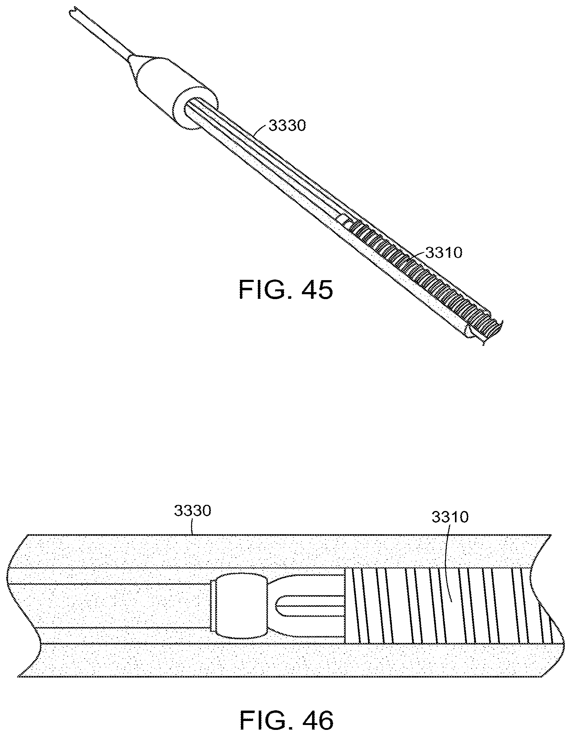
D00018

D00019

D00020

D00021

D00022

D00023
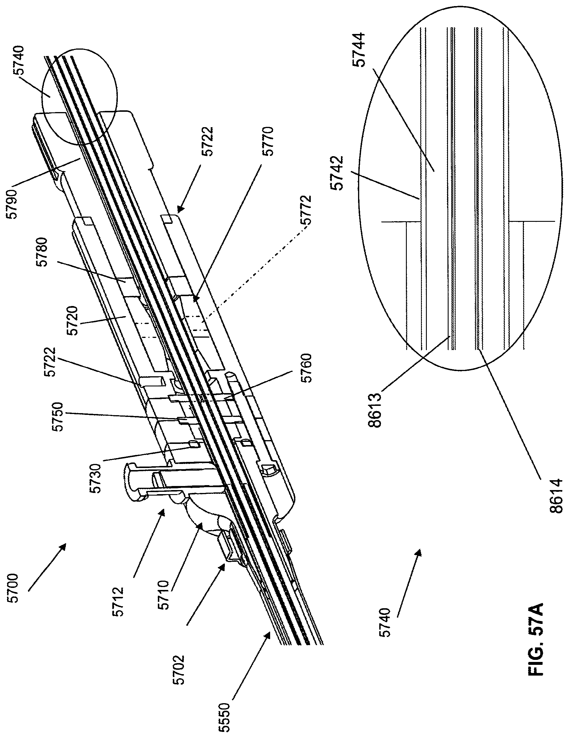
D00024

D00025

D00026

D00027

D00028

D00029
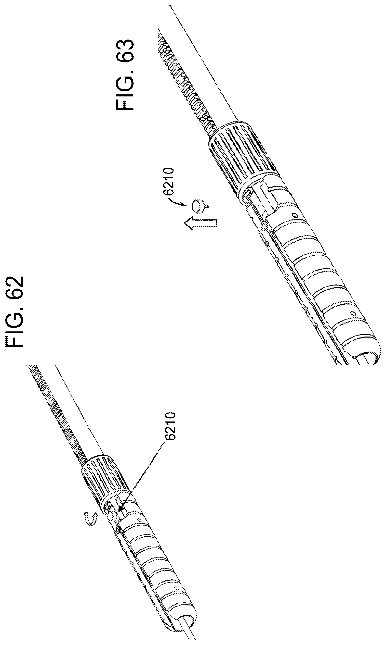
D00030
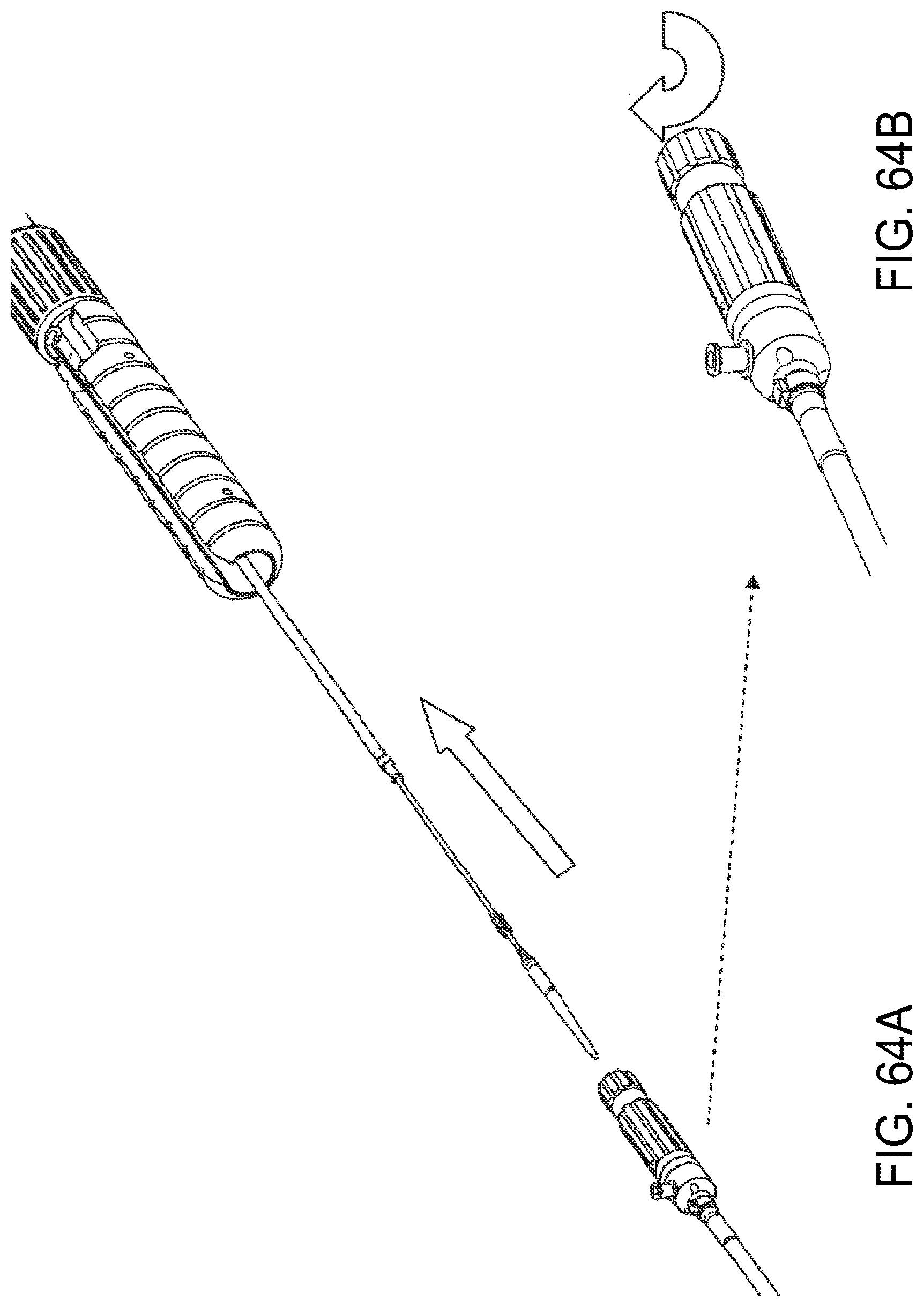
D00031

D00032
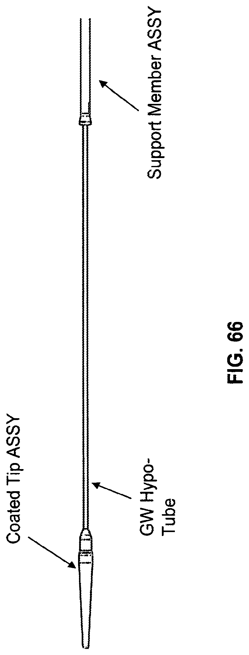
D00033

D00034

D00035
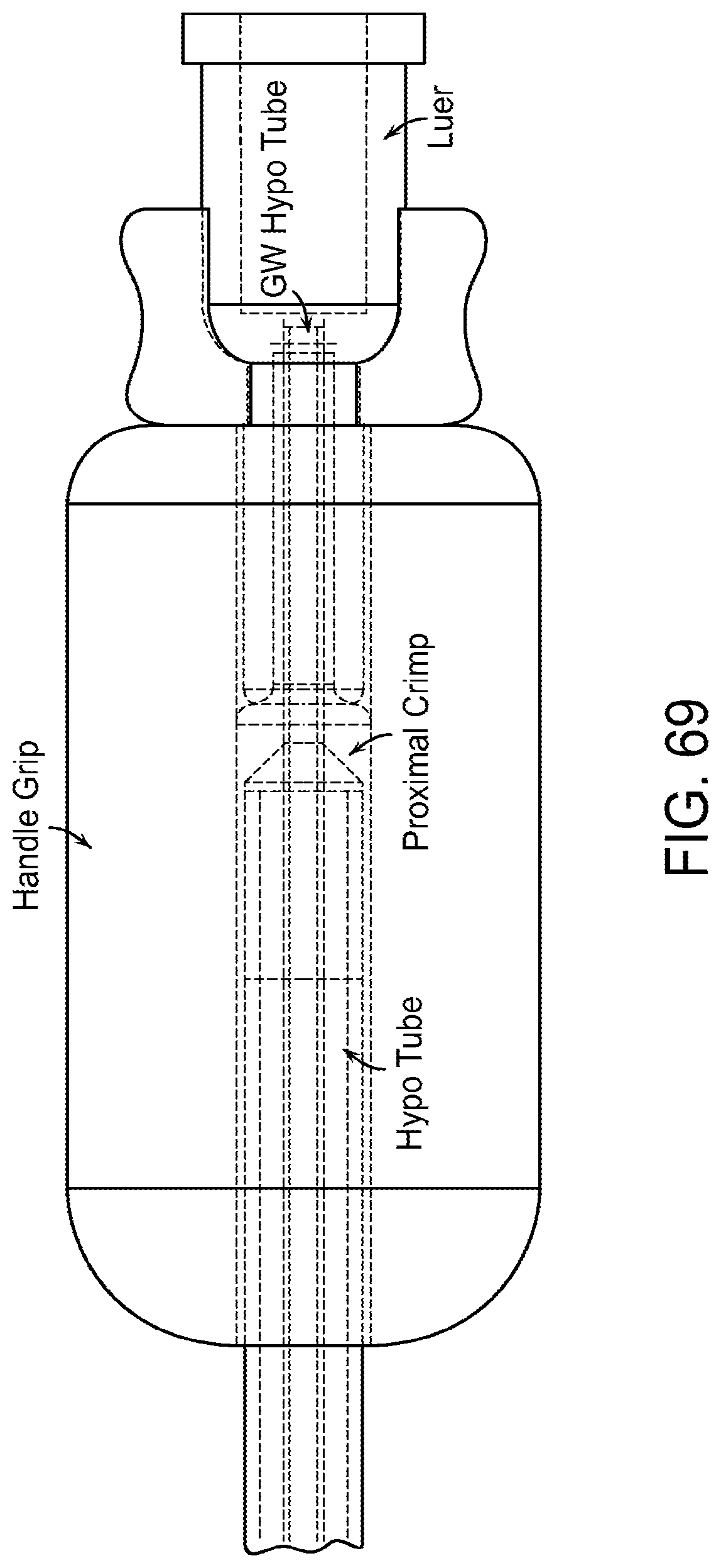
D00036

D00037

D00038

D00039

D00040

D00041

D00042
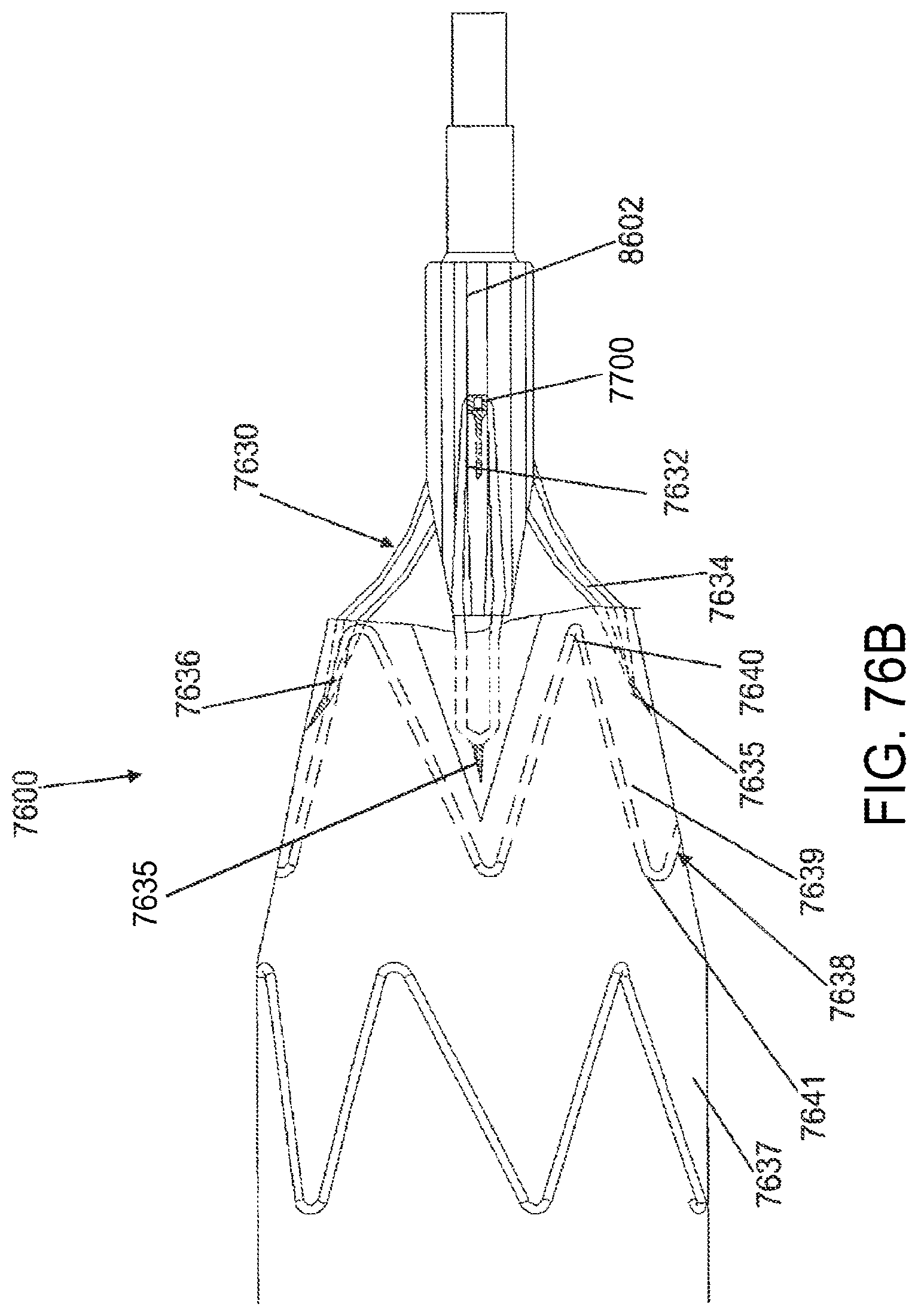
D00043
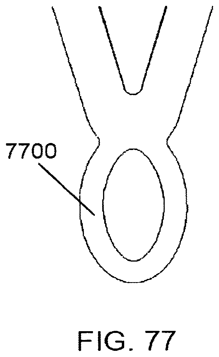
D00044

D00045

D00046
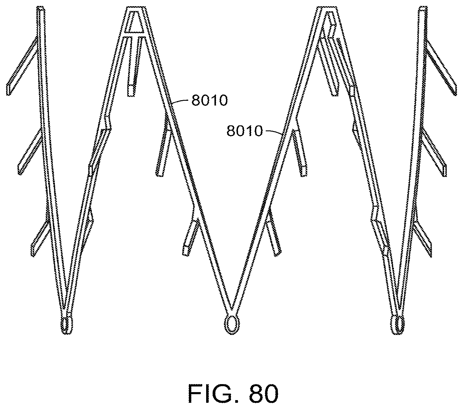
D00047

D00048

D00049

D00050

D00051

D00052

D00053

D00054

D00055

D00056

D00057
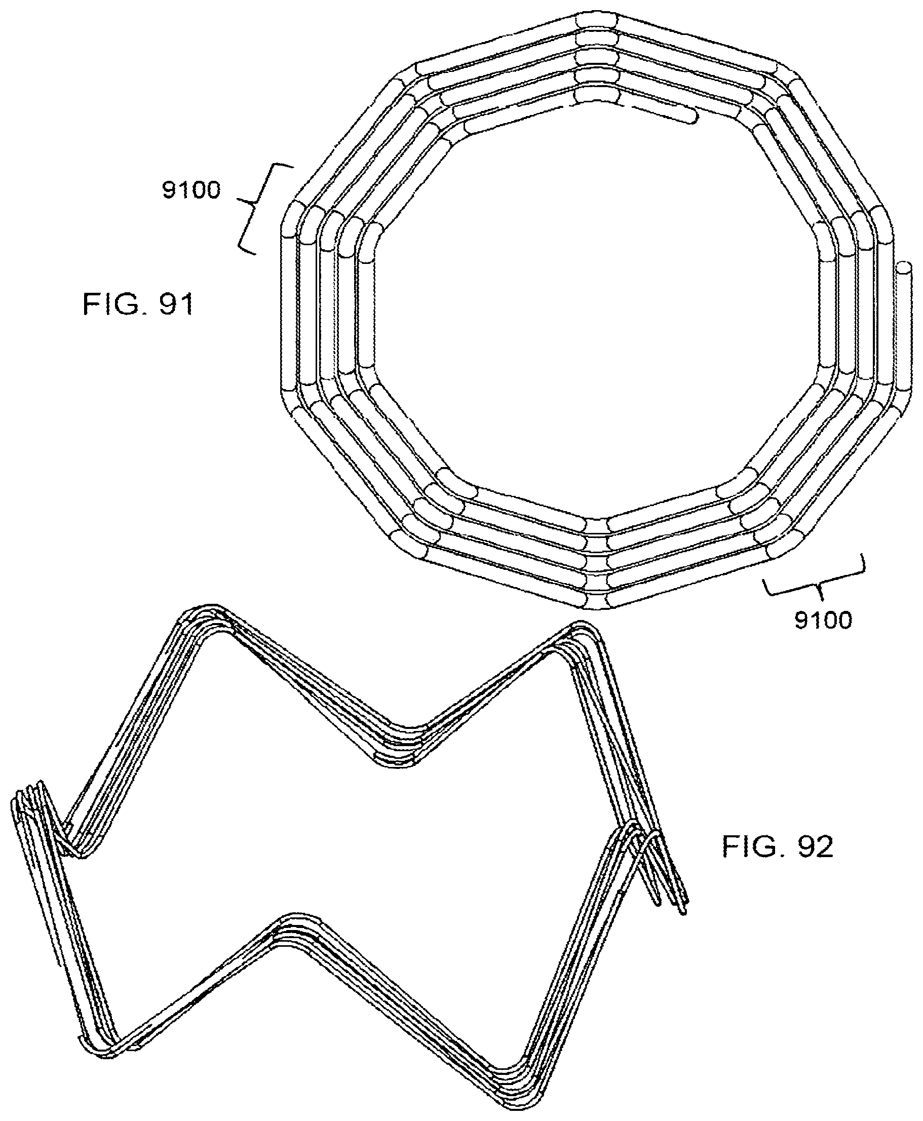
D00058

D00059

D00060

D00061
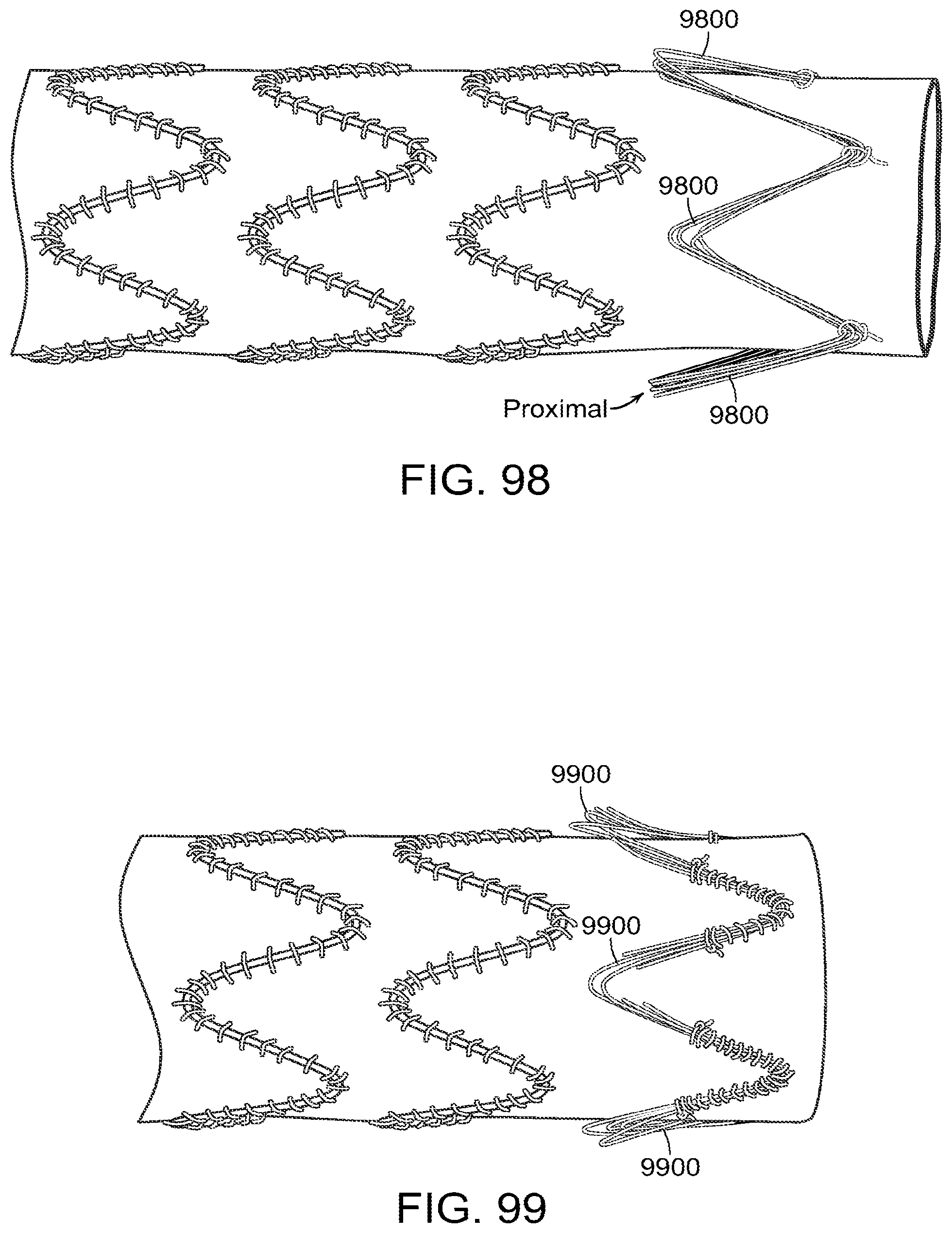
D00062

D00063

D00064

D00065
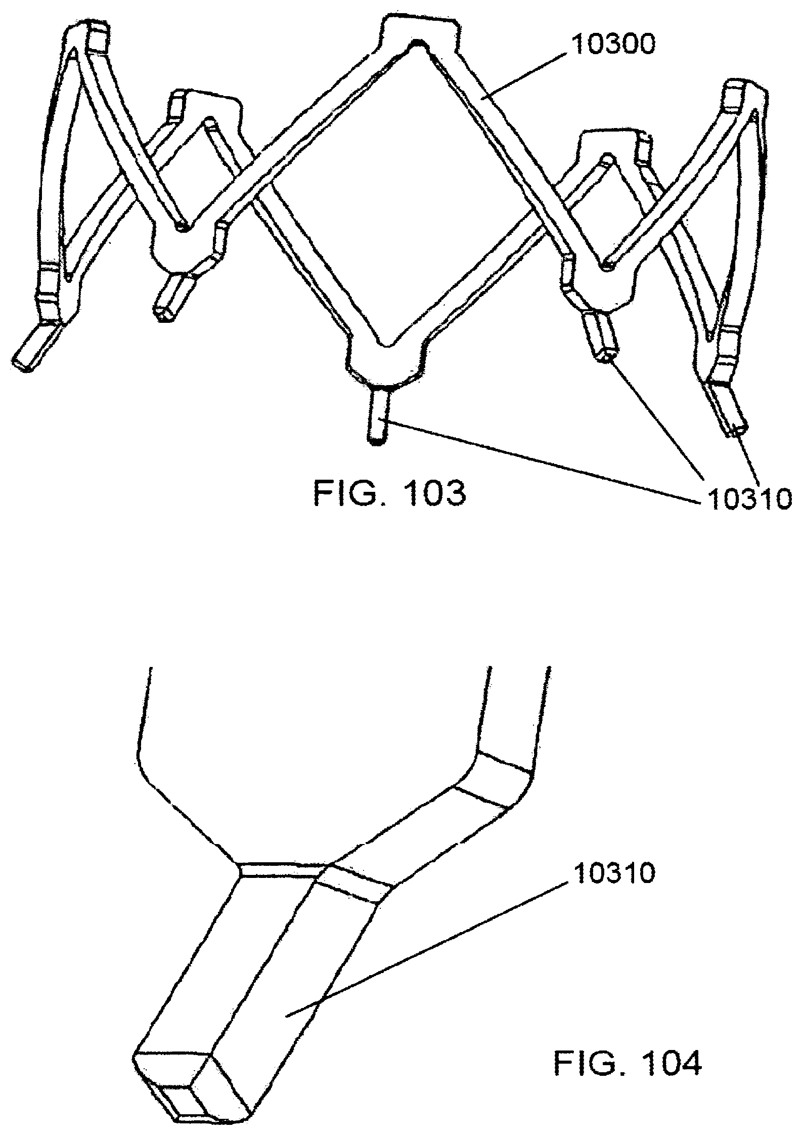
D00066

D00067

D00068
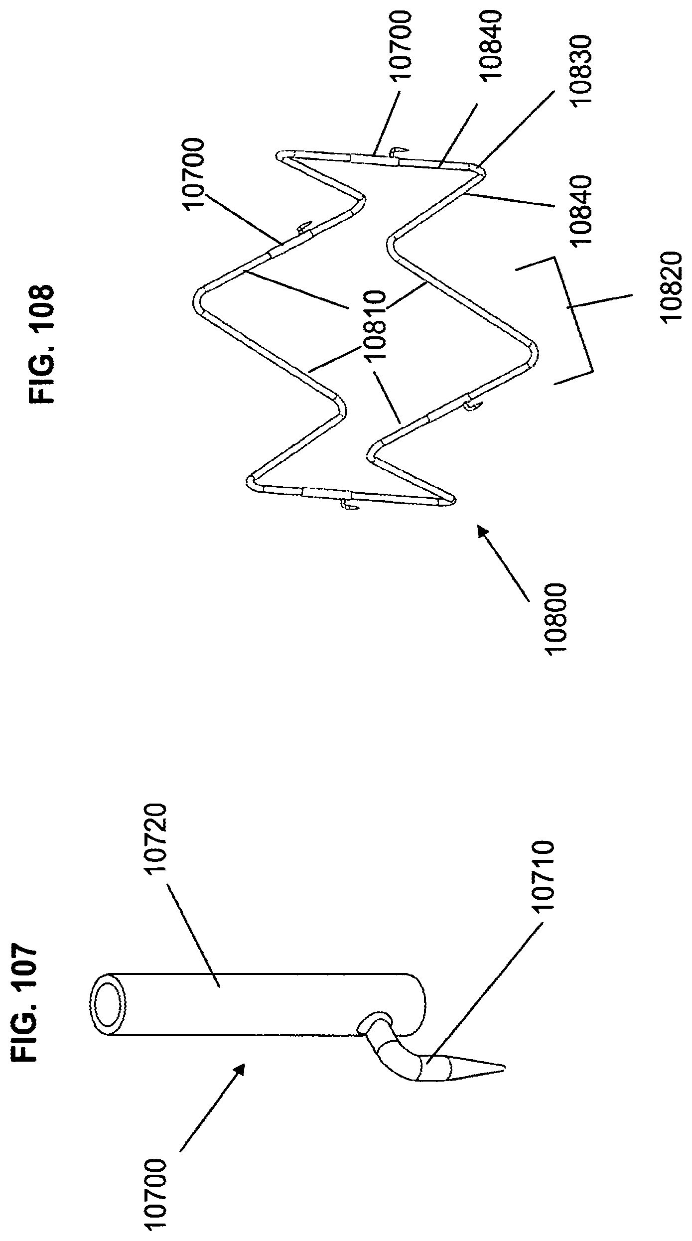
D00069

D00070

D00071

D00072

D00073

D00074
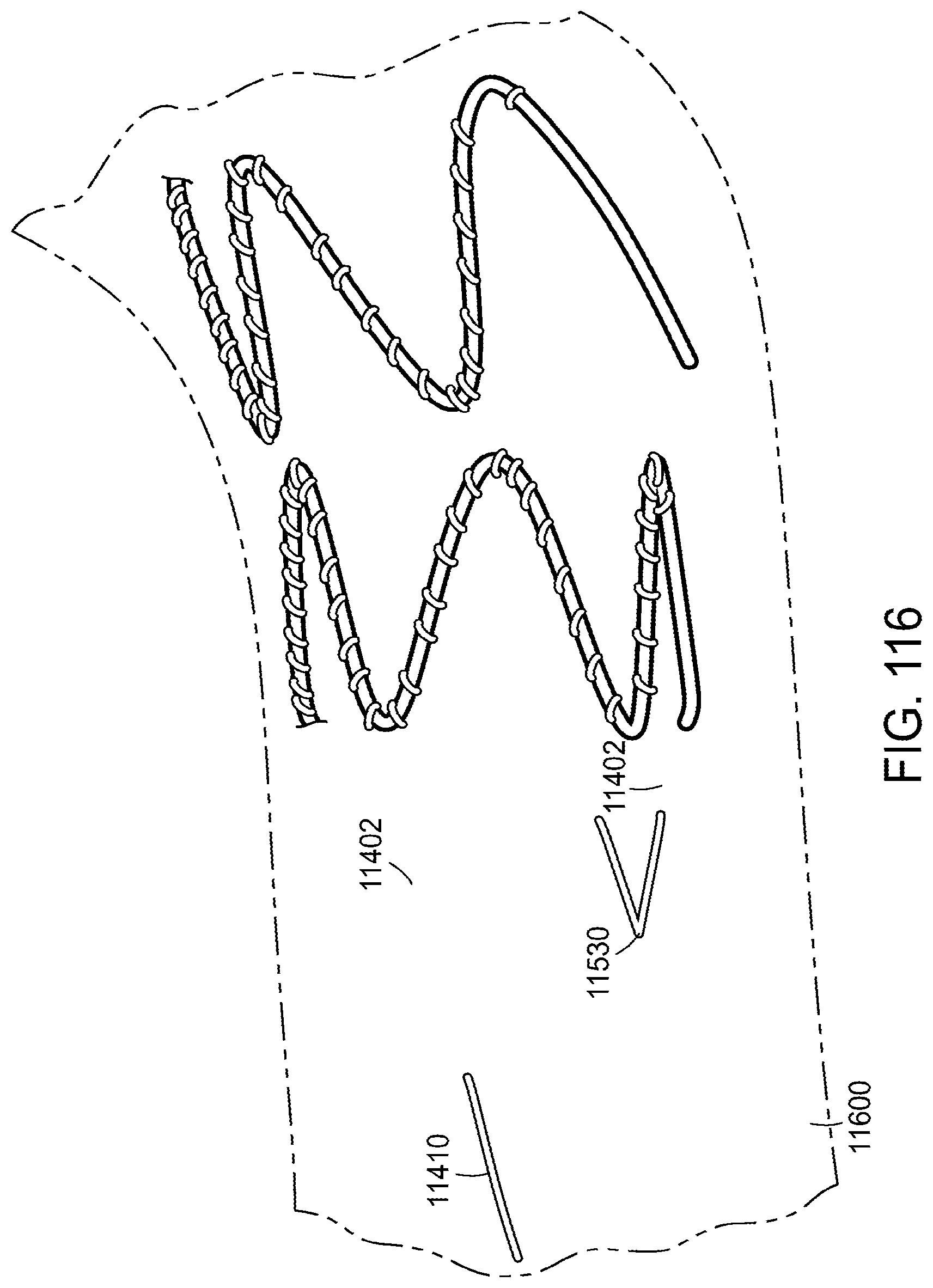
D00075

D00076

D00077

D00078

D00079
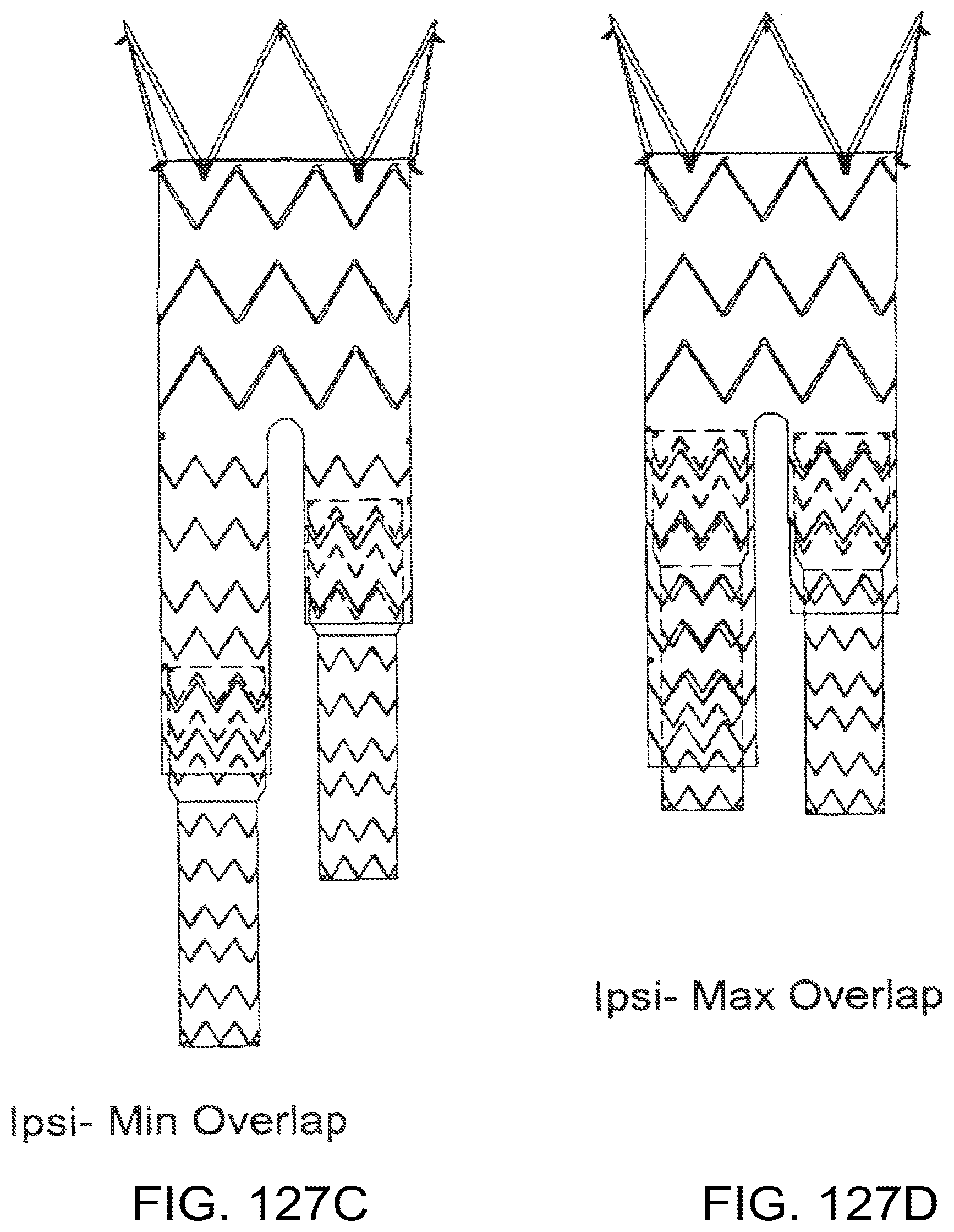
D00080
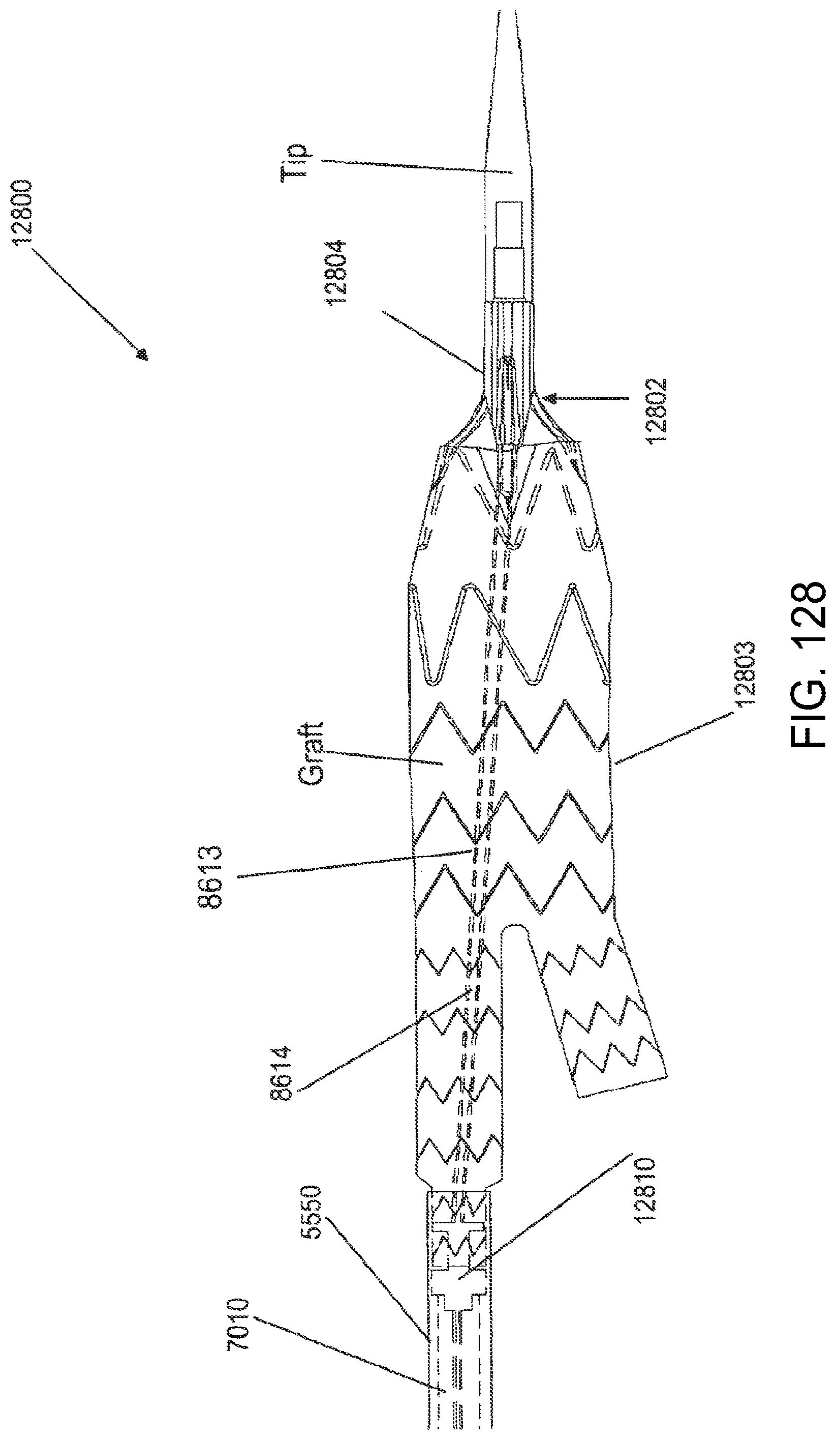
XML
uspto.report is an independent third-party trademark research tool that is not affiliated, endorsed, or sponsored by the United States Patent and Trademark Office (USPTO) or any other governmental organization. The information provided by uspto.report is based on publicly available data at the time of writing and is intended for informational purposes only.
While we strive to provide accurate and up-to-date information, we do not guarantee the accuracy, completeness, reliability, or suitability of the information displayed on this site. The use of this site is at your own risk. Any reliance you place on such information is therefore strictly at your own risk.
All official trademark data, including owner information, should be verified by visiting the official USPTO website at www.uspto.gov. This site is not intended to replace professional legal advice and should not be used as a substitute for consulting with a legal professional who is knowledgeable about trademark law.