Connector used with high-current terminal
Wu December 1, 2
U.S. patent number 10,855,014 [Application Number 16/511,208] was granted by the patent office on 2020-12-01 for connector used with high-current terminal. This patent grant is currently assigned to DINKLE ELECTRIC MACHINERY (CHINA) CO., LTD., DINKLE ENTERPRISE CO., LTD.. The grantee listed for this patent is DINKLE ELECTRIC MACHINERY (CHINA) CO., LTD., DINKLE ENTERPRISE CO., LTD.. Invention is credited to Shang-Tsai Wu.


View All Diagrams
| United States Patent | 10,855,014 |
| Wu | December 1, 2020 |
Connector used with high-current terminal
Abstract
A connector (10) used with a high-current terminal (100) includes a main body (1) and a conductive spacer (2). The main body (1) has a connecting portion (11) disposed at one end thereof and a pluggable portion (12) disposed at the other end thereof. The high-current terminal (100) is plugged into the pluggable portion (12). The conductive spacer (2) is disposed between the pluggable portion (12) and the high-current terminal (100). The conductive spacer (2) has a plurality of outer projections (21) pressed against the pluggable portion (12) and a plurality of inner projections (22) pressed against the high-current terminal (100). Thus, the number of electrical contact points is increased by means of the outer projections (21) and the inner projections (22) disposed between the pluggable portion (12) and the high-current terminal (100) such that the connector (10) has excellent electric conductivity and current adjustment capability.
| Inventors: | Wu; Shang-Tsai (New Taipei, TW) | ||||||||||
|---|---|---|---|---|---|---|---|---|---|---|---|
| Applicant: |
|
||||||||||
| Assignee: | DINKLE ENTERPRISE CO., LTD.
(New Taipei, TW) DINKLE ELECTRIC MACHINERY (CHINA) CO., LTD. (Jiangsu, CN) |
||||||||||
| Family ID: | 1000004216929 | ||||||||||
| Appl. No.: | 16/511,208 | ||||||||||
| Filed: | July 15, 2019 |
| Current U.S. Class: | 1/1 |
| Current CPC Class: | H01R 13/193 (20130101); H01R 13/05 (20130101); H01R 25/142 (20130101); H01R 13/53 (20130101) |
| Current International Class: | H01R 3/00 (20060101); H01R 13/193 (20060101); H01R 13/05 (20060101); H01R 25/14 (20060101); H01R 13/53 (20060101) |
| Field of Search: | ;439/62,851 |
References Cited [Referenced By]
U.S. Patent Documents
| 4781612 | November 1988 | Thrush |
| 4995825 | February 1991 | Korsunsky |
| 5156554 | October 1992 | Rudoy |
| 5496182 | March 1996 | Yasumura |
| 5505626 | April 1996 | Grabbe |
| 5582519 | December 1996 | Buchter |
| 5676559 | October 1997 | Laub |
| 6036519 | March 2000 | Lopata |
| 6296519 | October 2001 | Hashizawa |
| 6347950 | February 2002 | Yokoyama |
| 6402525 | June 2002 | Gugliotti |
| 6482049 | November 2002 | Swearingen |
| 6488549 | December 2002 | Weller |
| 6890214 | May 2005 | Brown |
| 7011548 | March 2006 | Bogiel |
| 7083433 | August 2006 | Misawa |
| 7476108 | January 2009 | Swain |
| 7613011 | November 2009 | Grundy |
| 8808039 | August 2014 | Mott |
| 8839513 | September 2014 | Nakamura |
| 9711897 | July 2017 | Ho |
| 10230191 | March 2019 | Lui |
| 2002/0028588 | March 2002 | Watanabe |
| 2002/0049006 | April 2002 | Zhao |
| 2004/0048496 | March 2004 | Chi |
| 2006/0014442 | January 2006 | Allgood et al. |
| 2007/0123084 | May 2007 | Takehara |
| 2007/0155194 | July 2007 | Vega Martinez |
| 2011/0111606 | May 2011 | Lee |
| 2012/0156947 | June 2012 | Tyler |
| 2019/0044267 | February 2019 | Lui et al. |
| 110011100 | Jul 2019 | CN | |||
| 102012001560 | Aug 2013 | DE | |||
| 102014005535 | Oct 2015 | DE | |||
Other References
|
Office Action dated Mar. 13, 2020 of the corresponding German patent application. cited by applicant. |
Primary Examiner: Riyami; Abdullah A
Assistant Examiner: Burgos-Guntin; Nelson R.
Attorney, Agent or Firm: Shih; Chun-Ming HDLS IPR Services
Claims
What is claimed is:
1. A connector used with a high-current terminal (100), comprising: a main body (1) having a connecting portion (11) disposed at one end thereof and a pluggable portion (12) disposed at the other end thereof, wherein the high-current terminal (100) is plugged into the pluggable portion (12); and a conductive spacer (2) disposed between the pluggable portion (12) and the high-current terminal (100), wherein the conductive spacer (2) is a U-shaped sheet body (23) having two wavy-shaped side plates parallel to each other, and each of the two wavy-shaped side plates has a plurality of wavy portions and a plurality of flat portions (25), and a plurality of through holes are formed on the plurality of wavy portions; wherein the plurality of wavy portions have a plurality of outer projections (21) pressed against the pluggable portion (12) and a plurality of inner projections (22) pressed against the high-current terminal (100).
2. The connector used with a high-current terminal (100) according to claim 1, wherein the pluggable portion (12) is a U-shaped clamp (13), wherein the conductive spacer (2) fits the U-shaped clamp (13).
3. The connector used with a high-current terminal (100) according to claim 2, wherein the U-shaped clamp (13) has two end edges (131) disposed in parallel with each other, wherein the U-shaped sheet body (23) has two ends bent to form two hook portions (231) surrounding and pressing against the two end edges (131).
4. The connector used with a high-current terminal (100) according to claim 1, wherein the pluggable portion (12) is a tube connector (14), wherein the conductive spacer (2) is an annular sheet body (24) fitting the tube connector (14).
5. The connector used with a high-current terminal (100) according to claim 4, wherein the tube connector (14) has an annular edge (141), wherein the annular sheet body (24) has a folded ring portion (241) which is disposed at an end thereof and is bent to surround and press against the annular edge (141).
6. The connector used with a high-current terminal (100) according to claim 1, wherein the plurality of flat portions (25) are disposed longitudinally and in parallel, and the conductive spacer (2) further has a plurality of first sections (26) and a plurality of second sections (27), wherein the first sections (26) and the second sections (27) are interlaced with each other and disposed between the flat portions (25).
7. The connector used with a high-current terminal (100) according to claim 6, wherein the outer projections (21) are a plurality of outer bent projections (211) which are formed in the first sections (26) and integrally connected between the flat portions (25), wherein the inner projections (22) are a plurality of inner bent projections (221) which are formed in the second sections (27) and integrally connected between the flat portions (25).
8. The connector used with a high-current terminal (100) according to claim 6, wherein the outer projections (21) comprise a plurality of first outer bent projections (212) which are formed in the first sections (26) and are integrally connected between the flat portions (25) and a plurality of second outer bent projections (213) which are formed in the first sections (26) and extend from a side of the flat portions (25), wherein the inner projections (22) comprise a plurality of first inner bent projections (222) which are formed in the second sections (27) and integrally connected between the flat portions (25) and a plurality of second inner bent projections (223) which are formed in the second sections (27) and extend from a side of the flat portions (25), wherein the first outer bent projections (212) and the second outer bent projections (213) are interlaced with each other and the first inner bent projections (222) and the second inner bent projections (223) are interlaced with each other.
9. The connector used with a high-current terminal (100) according to claim 6, wherein the outer projections (21) comprise a plurality of first outer bent projections (212') which are formed in the first sections (26) and integrally connected between the flat portions (25) and a plurality of second outer bent projections (213') which are formed in the second sections (27) and integrally connected between the flat portions (25), wherein the inner projections (22) comprise a plurality of first inner bent projections (222') which are formed in the first sections (26) and integrally connected between the flat portions (25) and a plurality of second inner bent projections (223') which are formed in the second sections (27) and integrally connected between the flat portions (25), wherein the first outer bent projections (212') and the first inner bent projections (222') are interlaced with each other and the second outer bent projections (213') and the second inner bent projections (223') are interlaced with each other.
10. The connector used with a high-current terminal (100) according to claim 6, wherein the outer projections (21) comprise a plurality of first outer bent projections (212'') which are formed in the first sections (26) and integrally connected between the flat portions (25) and a plurality of second outer bent projections (213') which are formed in the second sections (27) and extend from a side of the flat portions (25), wherein the inner projections (22) comprise a plurality of first inner bent projections (222'') which are formed in the first sections (26) and extend from a side of the flat portions (25) and a plurality of second inner bent projections (223'') which are formed in the second sections (27) and integrally connected between the flat portions (25), wherein the first outer bent projections (212'') and the first inner bent projections (222'') are interlaced with each other and the second outer bent projections (213'') and the second inner bent projections (223'') are interlaced with each other.
11. The connector used with a high-current terminal (100) according to claim 6, wherein each of the first sections (26) is provided with a plurality of first openings (261), wherein each of the second sections (27) is provided with a plurality of second openings (271), wherein the outer projections (21) are a plurality of outer bent projections (211') which are formed in the first sections (26) and extend into the first openings (261), wherein the inner projections (22) are a plurality of inner bent projections (221') which are formed in the second sections (27) and extend into the second openings (271).
Description
BACKGROUND OF THE INVENTION
Field of the Invention
The present invention relates to a connector structure and in particular to a connector which is used with a high-current terminal.
Description of Prior Art
A connector used with a high-current terminal is currently available in the market, which is used to connect the bus bar of the network energy equipment, unit base, servers, internet equipment, or industrial power distribution equipment to the circuit board. However, the connector used with the high-current terminal usually has the problems of insufficient electric conductivity and incapability of current adjustment.
In view of this, the inventor pays special attention to research with the application of related theory and tries to improve and overcome the above disadvantages regarding the above related art, which becomes the development goal of the inventor.
SUMMARY OF THE INVENTION
The present invention provides a connector used with a high-current terminal to increase the number of electrical contact points by means of plural outer projections and plural inner projections disposed between the pluggable portion and the high-current terminal such that the connector has excellent electric conductivity and current adjustment capability.
In the embodiments, the present invention provides a connector used with a high-current terminal. The connector comprises a main body and a conductive spacer. The main body has a connecting portion disposed at one end thereof and a pluggable portion disposed at the other end thereof; the high-current terminal is plugged into the pluggable portion. The conductive spacer is disposed between the pluggable portion and the high-current terminal; the conductive spacer has a plurality of outer projections pressed against the pluggable portion and a plurality of inner projections pressed against the high-current terminal.
According to the above description, the number of electrical contact points is increased by means of the outer projections and the inner projections disposed between the pluggable portion and the high-current terminal. The current flowing through the pluggable portion can be adjusted by adjusting the numbers of the outer projections and the inner projections such that the connector has excellent electric conductivity and current adjustment capability.
According to the above description, because the shapes of the outer projection and the inner projection generate spring force, the holding force of the pluggable portion on the high-current terminal can be adjusted by adjusting the spring force of the outer bent projections and the inner bent projections disposed between the pluggable portion and the high-current terminal.
BRIEF DESCRIPTION OF DRAWING
FIG. 1 is a perspective exploded view of the connector according to the first embodiment of the present invention;
FIG. 2 is a perspective schematic view of the conductive spacer according to the first embodiment of the present invention;
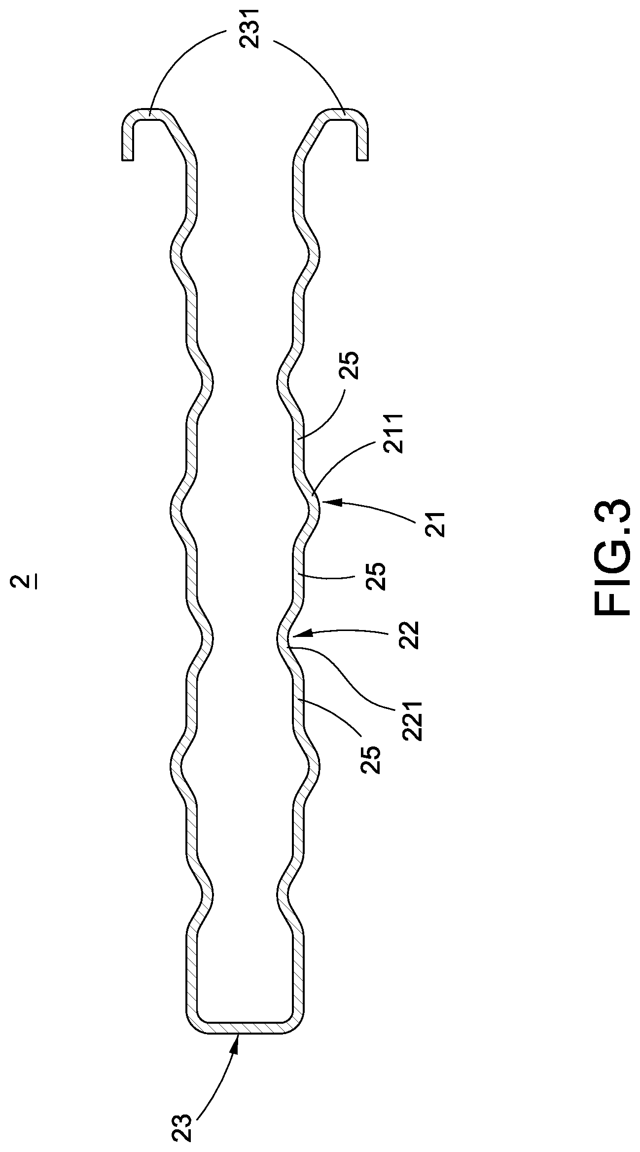
FIG. 3 is a cross-sectional view of the conductive spacer according to the first embodiment of the present invention;
FIG. 4 is an operational view of the connector according to the first embodiment of the present invention;
FIG. 5 is a perspective schematic view of the conductive spacer according to the second embodiment of the present invention;
FIG. 6 is a cross-sectional view of the conductive spacer according to the second embodiment of the present invention;
FIG. 7 is a perspective schematic view of the conductive spacer according to the third embodiment of the present invention;
FIG. 8 is a cross-sectional view of the conductive spacer according to the third embodiment of the present invention;
FIG. 9 is a perspective schematic view of the conductive spacer according to the fourth embodiment of the present invention;
FIG. 10 is a cross-sectional view of the conductive spacer according to the fourth embodiment of the present invention;
FIG. 11 is a perspective exploded view of the connector according to the fifth embodiment of the present invention; and
FIG. 12 is an operational view of the connector according to the fifth embodiment of the present invention.
DETAILED DESCRIPTION OF THE INVENTION
The technical features and details of the present invention are described below in reference to accompanying figures. However, the accompanying figures are only for reference and explanation, but not to limit the scope of the present invention.
Please refer to FIGS. 1-4. The present invention provides a connector used with a high-current terminal. The connector 10 mainly comprises a main body 1 and a conductive spacer 2. The connector 10 and the conductive spacer shown in FIGS. 1-4 belong to the first embodiment of the present invention.
As shown in FIGS. 1 and 4, the main body 1 is made of metal. The main body 1 has a connecting portion 11 disposed at one end thereof and a pluggable portion 12 disposed at the other end thereof. The high-current terminal 100 is plugged into the pluggable portion 12. The connecting portion 11 is used to be electrically connected to the bus bar.
As shown in FIGS. 1-4, the conductive spacer 2 is made of metal. The conductive spacer 2 is disposed between the pluggable portion 12 and the high-current terminal 100. The conductive spacer 2 has a plurality of outer projections 21 pressed against the pluggable portion 12 and a plurality of inner projections 22 pressed against the high-current terminal 100.
The details are given below. The conductive spacer 2 has a plurality of flat portions 25 disposed longitudinally and in parallel, a plurality of first sections 26, and a plurality of second sections 27; the first sections 26 and the second sections 27 are interlaced with each other and disposed between the flat portions 25. The outer projections 21 are a plurality of outer bent projections 211 which are formed in the first sections 26 and integrally connected between the flat portions 25; the inner projections 22 are a plurality of inner bent projections 221 which are formed in the second sections 27 and integrally connected between the flat portions 25.
In addition, in the current embodiment, the pluggable portion 12 is a U-shaped clamp 13 which has two end edges 131 disposed in parallel with each other. The conductive spacer 2 is a U-shaped sheet body 23 fitting the U-shaped clamp 13. The U-shaped sheet body 23 has two ends which are bent to form two hook portions 231 surrounding and pressing against the two end edges 131 such that the conductive spacer 2 can be fixed firmly to the pluggable portion 12.
FIGS. 1 and 4 show the operational state of the connector 10 of the present invention in which the conductive spacer 2 is disposed between the pluggable portion 12 and the high-current terminal 100 and has a plurality of outer projections 21 pressed against the pluggable portion 12 and a plurality of inner projections 22 pressed against the high-current terminal 100. In this way, the number of electrical contact points between the pluggable portion 12 and the high-current terminal 100 is increased by means of the outer projections 21 and the inner projections 22. Also, the current flowing through the pluggable portion 12 can be adjusted by adjusting the numbers of the outer projections 21 and the inner projections 22 such that the connector 10 has excellent electric conductivity and current adjustment capability.
Moreover, the outer projections 21 are composed of a plurality of outer bent projections 211; the inner projections 22 are composed of a plurality of inner bent projections 221. Because the shapes of the outer bent projections 211 and the inner bent projections 221 generate spring force, the holding force of the pluggable portion 12 on the high-current terminal 100 can be adjusted by adjusting the spring force of the outer bent projections 211 and the inner bent projections 221 disposed between the pluggable portion 12 and the high-current terminal 100.
Please refer to FIGS. 5 and 6, which show the connector 10 and the conductive spacer 2 according to the second embodiment of the present invention. The second embodiment is similar to the first embodiment. The difference between the first and the second embodiments is that the conductive spacers 2 of these two embodiments have different structures.
The further description is given below. The outer projections 21 comprise a plurality of first outer bent projections 212 which are formed in the first sections 26 and are integrally connected between the flat portions 25 and a plurality of second outer bent projections 213 which are formed in the first sections 26 and extend from a side of the flat portions 25. The inner projections 22 comprise a plurality of first inner bent projections 222 which are formed in the second sections 27 and integrally connected between the flat portions 25 and a plurality of second inner bent projections 223 which are formed in the second sections 27 and extend from a side of the flat portions 25. The first outer bent projections 212 and the second outer bent projections 213 are interlaced with each other; the first inner bent projections 222 and the second inner bent projections 223 are interlaced with each other. In this way, the shapes of the first outer bent projections 212, the second outer bent projections 213, the first inner bent projections 222, and the second inner bent projections 223 generate spring force, which have the same function and effect as the first embodiment.
Please refer to FIGS. 7 and 8, which show the connector 10 and the conductive spacer 2 according to the third embodiment of the present invention. The third embodiment is similar to the first embodiment. The difference between the first and the third embodiments is that the conductive spacers 2 of these two embodiments have different structures.
The detailed description is given below. The outer projections 21 comprise a plurality of first outer bent projections 212' which are formed in the first sections 26 and integrally connected between the flat portions 25 and a plurality of second outer bent projections 213' which are formed in the second sections 27 and integrally connected between the flat portions 25. The inner projections 22 comprise a plurality of first inner bent projections 222' which are formed in the first sections 26 and integrally connected between the flat portions 25 and a plurality of second inner bent projections 223' which are formed in the second sections 27 and integrally connected between the flat portions 25. The first outer bent projections 212' and the first inner bent projections 222' are interlaced with each other; the second outer bent projections 213' and the second inner bent projections 223' are interlaced with each other. In this way, the shapes of the first outer bent projections 212', the second outer bent projections 213', the first inner bent projections 222', and the second inner bent projections 223' generate spring force, which have the same function and effect as the first embodiment.
Please refer to FIGS. 9 and 10, which show the connector 10 and the conductive spacer 2 according to the fourth embodiment of the present invention. The fourth embodiment is similar to the first embodiment. The difference between the first and the fourth embodiments is that the conductive spacers 2 of these two embodiments have different structures.
The further description is given below. The outer projections 21 comprise a plurality of first outer bent projections 212'' which are formed in the first sections 26 and integrally connected between the flat portions 25 and a plurality of second outer bent projections 213'' which are formed in the second sections 27 and extend from a side of the flat portions 25. The inner projections 22 comprise a plurality of first inner bent projections 222'' which are formed in the first sections 26 and extend from a side of the flat portions 25 and a plurality of second inner bent projections 223'' which are formed in the second sections 27 and integrally connected between the flat portions 25. The first outer bent projections 212'' and the first inner bent projections 222'' are interlaced with each other; the second outer bent projections 213'' and the second inner bent projections 223'' are interlaced with each other. In this way, the shapes of the first outer bent projections 212'', the second outer bent projections 213'', the first inner bent projections 222'', and the second inner bent projections 223'' generate spring force, which have the same function and effect as the first embodiment.
Please refer to FIGS. 11 and 12, which show the connector 10 and the conductive spacer 2 according to the fifth embodiment of the present invention. The fifth embodiment is similar to the first embodiment. The difference between the first and the fifth embodiments is that the main bodies 1 and the conductive spacers 2 of these two embodiments have different structures.
The detailed description is given below. The pluggable portion 12 is a tube connector 14 and the conductive spacer 2 is an annular sheet body 24 fitting the tube connector 14. The tube connector 14 has an annular edge 141. The annular sheet body 24 has a folded ring portion 241 which is disposed at an end thereof and is bent to surround and press against the annular edge 141 such that the conductive spacer 2 can be fixed firmly to the pluggable portion 12.
Further, each of the first sections 26 is provided with a plurality of first openings 261; each of the second sections 27 is provided with a plurality of second openings 271. The outer projections 21 are a plurality of outer bent projections 211' which are formed in the first sections 26 and extend into the first openings 261. The inner projections 22 are a plurality of inner bent projections 221' which are formed in the second sections 27 and extend into the second openings 271. Thus, the shapes of the outer bent projections 211' and the inner bent projections 221' generate spring force, which have the same function and effect as the first embodiment.
In summary, the connector used with a high-current terminal of the present invention is not anticipated by the similar products and is not used in public. Also, it is indeed novel, useful, and non-obvious to be patentable. Please examine the application carefully and grant it as a formal patent for protecting the rights of the inventor.
* * * * *
D00000
D00001
D00002
D00003
D00004
D00005
D00006
D00007
D00008
D00009
D00010
D00011
D00012

XML
uspto.report is an independent third-party trademark research tool that is not affiliated, endorsed, or sponsored by the United States Patent and Trademark Office (USPTO) or any other governmental organization. The information provided by uspto.report is based on publicly available data at the time of writing and is intended for informational purposes only.
While we strive to provide accurate and up-to-date information, we do not guarantee the accuracy, completeness, reliability, or suitability of the information displayed on this site. The use of this site is at your own risk. Any reliance you place on such information is therefore strictly at your own risk.
All official trademark data, including owner information, should be verified by visiting the official USPTO website at www.uspto.gov. This site is not intended to replace professional legal advice and should not be used as a substitute for consulting with a legal professional who is knowledgeable about trademark law.