Sodium-halogen secondary cell
Bhavaraju , et al. December 1, 2
U.S. patent number 10,854,929 [Application Number 14/956,078] was granted by the patent office on 2020-12-01 for sodium-halogen secondary cell. This patent grant is currently assigned to FIELD UPGRADING USA, INC.. The grantee listed for this patent is FIELD UPGRADING USA, INC.. Invention is credited to Sai Bhavaraju, Alexis Eccleston, Mathew Robins.


| United States Patent | 10,854,929 |
| Bhavaraju , et al. | December 1, 2020 |
Sodium-halogen secondary cell
Abstract
An intermediate temperature sodium-halogen secondary cell that includes a negative electrode compartment housing a negative, molten sodium-based electrode and a positive electrode compartment housing a current collector disposed in a highly conductive molten positive electrolyte. A sodium halide (NaX) positive electrode is disposed in a molten positive electrolyte comprising one or more AlX.sub.3 salts, wherein X may be the same or different halogen selected from Cl, Br, and I, wherein the ratio of NaX to AlX.sub.3 is greater than or equal to one. A sodium ion conductive solid electrolyte membrane separates the molten sodium negative electrode from the molten positive electrolyte. The secondary cell operates at a temperature in the range from about 80.degree. C. to 210.degree. C.
| Inventors: | Bhavaraju; Sai (West Jordan, UT), Robins; Mathew (Saratoga Springs, UT), Eccleston; Alexis (Midvale, UT) | ||||||||||
|---|---|---|---|---|---|---|---|---|---|---|---|
| Applicant: |
|
||||||||||
| Assignee: | FIELD UPGRADING USA, INC.
(Broomfield, CO) |
||||||||||
| Family ID: | 1000005217211 | ||||||||||
| Appl. No.: | 14/956,078 | ||||||||||
| Filed: | December 1, 2015 |
Prior Publication Data
| Document Identifier | Publication Date | |
|---|---|---|
| US 20160087313 A1 | Mar 24, 2016 | |
Related U.S. Patent Documents
| Application Number | Filing Date | Patent Number | Issue Date | ||
|---|---|---|---|---|---|
| 14511031 | Oct 9, 2014 | ||||
| 14019651 | Sep 6, 2013 | 9413036 | |||
| 62087507 | Dec 4, 2014 | ||||
| 61888933 | Oct 9, 2013 | ||||
| 61697608 | Sep 6, 2012 | ||||
| 61777967 | Mar 12, 2013 | ||||
| 61781530 | Mar 14, 2013 | ||||
| 61736444 | Dec 12, 2012 | ||||
| Current U.S. Class: | 1/1 |
| Current CPC Class: | H01M 4/381 (20130101); H01M 10/4235 (20130101); H01M 10/0563 (20130101); H01M 10/0562 (20130101); H01M 4/62 (20130101); H01M 4/388 (20130101); H01M 10/36 (20130101); H01M 2/40 (20130101); H01M 10/054 (20130101); H01M 10/399 (20130101); H01M 4/661 (20130101); H01M 2300/0054 (20130101); H01M 2300/0068 (20130101) |
| Current International Class: | H01M 10/00 (20060101); H01M 4/38 (20060101); H01M 10/0563 (20100101); H01M 10/054 (20100101); H01M 10/39 (20060101); H01M 10/42 (20060101); H01M 10/36 (20100101); H01M 10/0562 (20100101); H01M 4/62 (20060101); H01M 2/40 (20060101); H01M 4/66 (20060101) |
References Cited [Referenced By]
U.S. Patent Documents
| 3546021 | December 1970 | Gale |
| 3632448 | January 1972 | Beltzer |
| 3877984 | April 1975 | Werth |
| 3918991 | November 1975 | Hess |
| 4020246 | April 1977 | Seo et al. |
| 4041215 | August 1977 | Kormanyos et al. |
| 4162351 | July 1979 | Putt et al. |
| 4244986 | January 1981 | Paruso et al. |
| 4307164 | December 1981 | Church et al. |
| 4375501 | March 1983 | Peled et al. |
| 4427747 | January 1984 | Bennett et al. |
| 4485154 | November 1984 | Remick et al. |
| 4546055 | October 1985 | Coetzer et al. |
| 4579796 | April 1986 | Muramatsu |
| 4753858 | June 1988 | Jow et al. |
| 4828939 | May 1989 | Turley et al. |
| 4842963 | June 1989 | Ross, Jr. et al. |
| 4937155 | June 1990 | Tokoi et al. |
| 5051325 | September 1991 | Shishikura et al. |
| 5057206 | October 1991 | Engel et al. |
| 5139897 | August 1992 | Wedlake |
| 5213908 | May 1993 | Hagedorn |
| 5264298 | November 1993 | Townsend |
| 5290405 | March 1994 | Joshi et al. |
| 5342709 | August 1994 | Yahnke et al. |
| 5422197 | June 1995 | Zito |
| 5427873 | June 1995 | Shuster |
| 5516598 | May 1996 | Visco et al. |
| 5525442 | June 1996 | Shuster |
| 5536594 | July 1996 | Galloway |
| 5541019 | July 1996 | Anani et al. |
| 5552244 | September 1996 | Griffin et al. |
| 5563006 | October 1996 | Von Benda et al. |
| 5580430 | December 1996 | Balagopal et al. |
| 5604053 | February 1997 | Coetzer et al. |
| 5648183 | July 1997 | Licht et al. |
| 5686201 | November 1997 | Chu |
| 5695632 | December 1997 | Brons et al. |
| 5780186 | July 1998 | Casey, Jr. |
| 5856047 | January 1999 | Venkatesan et al. |
| 5882812 | March 1999 | Visco et al. |
| 5935421 | August 1999 | Brons et al. |
| 6017651 | January 2000 | Nimon et al. |
| 6025094 | February 2000 | Visco et al. |
| 6030720 | February 2000 | Chu et al. |
| 6033343 | March 2000 | Licht |
| 6033796 | March 2000 | Baji |
| 6110236 | August 2000 | Tsang et al. |
| 6153328 | November 2000 | Colborn |
| 6159634 | December 2000 | Yen et al. |
| 6165644 | December 2000 | Nimon et al. |
| 6200704 | March 2001 | Katz et al. |
| 6210564 | April 2001 | Brons et al. |
| 6210832 | April 2001 | Visco et al. |
| 6214061 | April 2001 | Visco et al. |
| 6225002 | May 2001 | Nimon et al. |
| 6248476 | June 2001 | Sun et al. |
| 6248481 | June 2001 | Visco et al. |
| 6265100 | July 2001 | Saaski et al. |
| 6270923 | August 2001 | Bito et al. |
| 6291090 | September 2001 | Kuznetsov et al. |
| 6310960 | October 2001 | Saaski et al. |
| 6355379 | March 2002 | Ohshita et al. |
| 6358643 | March 2002 | Katz et al. |
| 6368486 | April 2002 | Thompson et al. |
| 6376123 | April 2002 | Chu |
| 6402795 | June 2002 | Chu et al. |
| 6410181 | June 2002 | Spillman et al. |
| 6413284 | July 2002 | Chu et al. |
| 6413285 | July 2002 | Chu et al. |
| 6416903 | July 2002 | Fierro et al. |
| 6432584 | August 2002 | Visco et al. |
| 6537701 | March 2003 | Nimon et al. |
| 6610440 | August 2003 | LaFollette et al. |
| 6632573 | October 2003 | Nimon et al. |
| 6737197 | May 2004 | Chu et al. |
| 6767665 | July 2004 | Ohrem |
| 6787019 | September 2004 | Jacobson et al. |
| 6852450 | February 2005 | Hwang et al. |
| 6881234 | April 2005 | Towsley |
| 6911280 | June 2005 | De Jonghe et al. |
| 6955753 | October 2005 | Gomez |
| 6955866 | October 2005 | Nimon et al. |
| 6991662 | January 2006 | Visco et al. |
| 7070632 | July 2006 | Visco et al. |
| 7144654 | December 2006 | LaFollette et al. |
| 7166384 | January 2007 | LaFollette et al. |
| 7214443 | May 2007 | Clarke et al. |
| 7259126 | August 2007 | Gordon et al. |
| 7273680 | September 2007 | Durkot |
| 7282295 | October 2007 | Visco et al. |
| 7282296 | October 2007 | Visco et al. |
| 7282302 | October 2007 | Visco et al. |
| 7314681 | January 2008 | Randell et al. |
| 7390591 | June 2008 | Visco et al. |
| 7432017 | October 2008 | Visco et al. |
| 7482096 | January 2009 | De Jonghe et al. |
| 7491458 | February 2009 | Visco et al. |
| 8012621 | September 2011 | Joshi et al. |
| 8088270 | January 2012 | Gordon et al. |
| 8168321 | May 2012 | Shelekhin et al. |
| 8883339 | November 2014 | Choi |
| 8968902 | March 2015 | Coors et al. |
| 9413036 | August 2016 | Bhavaraju |
| 9431681 | August 2016 | Joshi |
| 2002/0150818 | October 2002 | Amatucci et al. |
| 2002/0172871 | November 2002 | Schucker |
| 2004/0065543 | April 2004 | Kovarsky |
| 2005/0006252 | January 2005 | Korpel et al. |
| 2005/0016857 | January 2005 | Kovarsky et al. |
| 2005/0109617 | May 2005 | Ono et al. |
| 2005/0260460 | November 2005 | Kishi et al. |
| 2006/0141346 | June 2006 | Gordon et al. |
| 2006/0177732 | August 2006 | Visco et al. |
| 2006/0226022 | October 2006 | Balagopal et al. |
| 2006/0257734 | November 2006 | Obata et al. |
| 2007/0048610 | March 2007 | Tsang et al. |
| 2007/0154762 | July 2007 | Schucker |
| 2007/0221265 | September 2007 | Affinito et al. |
| 2008/0268327 | October 2008 | Gordon et al. |
| 2009/0061288 | March 2009 | Gordon et al. |
| 2009/0134040 | May 2009 | Gordon et al. |
| 2009/0134842 | May 2009 | Joshi et al. |
| 2009/0136830 | May 2009 | Gordon |
| 2009/0189567 | June 2009 | Joshi et al. |
| 2009/0212743 | August 2009 | Hagiwara et al. |
| 2010/0044241 | February 2010 | Pendleton et al. |
| 2010/0089762 | April 2010 | Gordon |
| 2010/0239893 | September 2010 | Gordon et al. |
| 2010/0261051 | October 2010 | Okada et al. |
| 2010/0279165 | November 2010 | Lemmon |
| 2010/0285372 | November 2010 | Lee et al. |
| 2011/0104526 | May 2011 | Boxley et al. |
| 2011/0127967 | June 2011 | Soloveichik |
| 2011/0057135 | August 2011 | Boxley et al. |
| 2012/0015256 | January 2012 | Komaba et al. |
| 2012/0021273 | January 2012 | Ohmori et al. |
| 2012/0045695 | February 2012 | Sheem et al. |
| 2012/0126752 | May 2012 | Joshi et al. |
| 2012/0141856 | June 2012 | Gordon et al. |
| 2012/0164524 | June 2012 | Bogdan et al. |
| 2012/0061823 | July 2012 | Boxley et al. |
| 2012/0214043 | August 2012 | Olschimke et al. |
| 2012/0219833 | August 2012 | Coors et al. |
| 2012/0219838 | August 2012 | Coors et al. |
| 2012/0219843 | August 2012 | Bogdan et al. |
| 2013/0052525 | February 2013 | Kageura et al. |
| 2013/0130085 | May 2013 | Choi |
| 2013/0196224 | August 2013 | Kim et al. |
| 2014/0030571 | January 2014 | Bhavaraju et al. |
| 2014/0065456 | March 2014 | Bhavaraju et al. |
| 2014/0170443 | June 2014 | Bhavaraju et al. |
| 2935655 | Oct 2015 | EP | |||
| 2973832 | Jan 2016 | EP | |||
| 2115522 | Jul 1972 | FR | |||
| 2301108 | Sep 1976 | FR | |||
| 2518320 | Jun 1983 | FR | |||
| 21599661 | Dec 1985 | GB | |||
| 59-75985 | Apr 1984 | JP | |||
| 61-032366 | Feb 1986 | JP | |||
| 62186470 | Aug 1987 | JP | |||
| 08-017465 | Jan 1996 | JP | |||
| 10162807 | Jun 1998 | JP | |||
| 2001-307709 | Nov 2001 | JP | |||
| 2008293678 | Dec 2008 | JP | |||
| 2008300173 | Dec 2008 | JP | |||
| 201181971 | Apr 2011 | JP | |||
| 2015-531218 | Sep 2015 | JP | |||
| 100651246 | Aug 2005 | KR | |||
| 20070021110 | Feb 2007 | KR | |||
| WO2012061823 | Aug 1992 | WO | |||
| WO9416468 | Jul 1994 | WO | |||
| WO2005038953 | Apr 2005 | WO | |||
| WO-2005/091946 | Oct 2005 | WO | |||
| WO2013154349 | Oct 2013 | WO | |||
| WO-2014/039762 | Mar 2014 | WO | |||
| WO2014159542 | Oct 2014 | WO | |||
Other References
|
Machine translation of FR 2115522, obtained Mar. 6, 2019 (Year: 1972). cited by examiner . Akhtar, Kiran Q. , "Non Final Office Action", U.S. Appl. No. 14/040,241, dated Feb. 24, 2017, 1-21. cited by applicant . Gotz, Heide , "European Search Report", European Patent Application No. EP10829189.9, dated Nov. 18, 2016, 1-7. cited by applicant . Parsons, Thomas , "Non Final Office Action", U.S. Appl. No. 13/466,844, dated May 19, 2017, 1-10. cited by applicant . Unknown, , "Examination Report", Australian Patent Application No. 2013364191, dated Apr. 4, 2017, 1-3. cited by applicant . Young, Lee W., "International Search Report", PCT Search Report for App. No. PCT/US 08/10435, (dated Nov. 25, 2008),1-2. cited by applicant . Young, Lee W., "Written Opinion of the International Searching Authority", PCT Written Opinion for App. No. PCT/US 08/10435i, (dated Nov. 25, 2008),1-4. cited by applicant . Armand, Michel et al., "Ionic-liquid materials for the electrochemical challenges of the future", Nature Materials, (Jul. 24, 2009),621-629. cited by applicant . Doyle, Kevin P., et al., "Dentrite-Free Electrochemical Deposition of Li--Na Alloys from an Ionic Liquid Electrolyte", Journal of the Electrochemical Society, (May 2006),A1353-A1357. cited by applicant . Kim, K et al., "Electrochemical Investigation of Quaternary Ammonium/Aluminum Chloride Ionic Liquids", Journal of the Electrochemical Society, (Jun. 2004),A1168-A1172. cited by applicant . Kim, Ketack et al., "The Role of Additives in the Electroreduction of Sodium Ions in Chloroaluminate-Based Ionic Liquids",Journal of the Electrochemical Society, (Dec. 2004),E9-E13. cited by applicant . Lang, Christopher M., et al., "Cation Electrochemical Stability in Chloroaluminate Ionic Liquids", J. Phys. Chem., (2005),19454-19462. cited by applicant . Salminen, Justin et al., "Ionic liquids for rechargeable lithium batteries", Lawrence Berkeley National Laboratory, (Sep. 21),1-19. cited by applicant . Cullen, Sean P., "Office Action for U.S. Appl. No. 12/205,759", (dated Sep. 16, 2010),1-22. cited by applicant . Cullen, Sean P., "Office Action for U.S. Appl. No. 12/205,759", (dated Apr. 13, 2011),1-15. cited by applicant . Lee, Kang Young "International Search Report", International App. No. PCT/US2010/055718, (dated Jun. 21, 2011),1-3. cited by applicant . Lee, Kang Young "Written Opinion", International App. No. PCT/US2010/055718, (dated Jun. 21, 2011),1-3. cited by applicant . Cullen, Sean P., "Non-Final Office Action", U.S. Appl. No. 12/725,319, (dated Jan. 6, 2012),1-10. cited by applicant . Cullen, Sean P., "Final Office Action", U.S. Appl. No. 12/725,319, (dated Apr. 27, 2012),1-12. cited by applicant . Cho, Jun B., "International Search Report", PCT App. No. US2010/027535 (Corresponding to U.S. Appl. No. 12/725,319), (dated Oct. 20, 2010),1-4. cited by applicant . Cho, Jun B., "Written Opinion of the International Searching Authority", PCT App. No. US2010/027535 (Corresponding to U.S. Appl. No. 12/725,319), (dated Oct. 20, 2010),1-5. cited by applicant . Ryu, et al., "Bibliographical Data and Abstract (English Language)", Application Publication for US2007154814, Corresponding to KR10-0651246, (Aug. 22, 2005),1. cited by applicant . Wiedemann, Eric "Supplementary European Search Report", European Patent Application No. 10754004.9 (Corresponding to U.S. Appl. No. 12/725,319, (dated May 16, 2012),1-6. cited by applicant . Lee, Kang Y., "International Search Report", PCT App. No. US2010/055718 (Corresponding to U.S. Appl. No. 12/940,864), (dated Jun. 21, 2011),1-3. cited by applicant . Lee, Kang Y., "Written Opinion of the International Searching Authority", PCT App. No. US2010/055718 (Corresponding to U.S. Appl. No. 12/940,864, (dated Jun. 21, 2011),1-3. cited by applicant . Suzuki, et al., "Bibliographical Data and Abstract (English Language)", Japanese Patent application JP62-186470, (Aug. 14, 1987),1-2. cited by applicant . Sonoda, et al., "Bibliographical Data and Abstract (English Translation)", Japanese Patent Application JP-59-75985, (Apr. 28, 1984),1-2. cited by applicant . Abraham, et al., "A Low Temperature Na-S Battery Incorporating a Soluble S Cathode", ElectroChimica Acta, 1978, vol. 23, Pergamon Press Ltd., (Jun. 1, 1978),501-507. cited by applicant . Yun, Cho K., "Internationial Search Report", PCT App. No. PCT/US2012/036959 (corresponding to U.S. Appl. No. 13/466,844), (dated Nov. 23, 2012),1-3. cited by applicant . Yun, Cho K., "Written Opinion of the International Searching Authority", PCT App. No. PCT/US2012/036959 (corresponding to U.S. Appl. No. 13/466,844), (dated Nov. 23, 2012),1-5. cited by applicant . Cullen, Sean P., "Non Final Office Action", U.S. Appl. No. 12/205,759, (dated Apr. 5, 2013),1-17. cited by applicant . Lee, Dong W., "International Serach Report", PCT Application No. PCT/US13/68552 (Corresponding to U.S. Appl. No. 14/072,468, (dated Jan. 24, 2014),1-3. cited by applicant . Lee, Dong W., "Written Opinion of the International Searching Authority", PCT Application No. PCT/US2013/68552 (Corresponding to U.S. Appl. No. 14/072,468), (dated Jan. 24, 2014),1-5. cited by applicant . Lee, Dong W., "International Search Report", PCT Application No. PCT/US13/62386 (Corresponding to U.S. Appl. No. 14/040,241), (dated Dec. 23, 2013),1-3. cited by applicant . Lee, Dong W., "Written Opinion of the International Search Authority", PCT Application No. PCT/US2013/62386 (Corresponding to U.S. Appl. No. 14/040,241), (dated Dec. 23, 2014),1-5. cited by applicant . Lee, Dong W., "International Search Report", PCT Application No. PCT/US2013/058403 (Corresponding to U.S. Appl. No. 14/019,651), (dated Dec. 2, 2013),1-3. cited by applicant . Lee, Dong W., "Written Opinion of the International Searching Authority", PCT Application No. PCT/US2013/058403 (Corresponding to U.S. Appl. No. 14/019,651, (dated Dec. 2, 2013),1-6. cited by applicant . Marks, Jacob B., "Non Final Office Action", U.S. Appl. No. 14/469,865, (dated Apr. 7, 2015),1-6. cited by applicant . Shin, Ju C., "International Search Report", PCT Application No. PCT/US2014/059954 (Corresponding with U.S. Appl. No. 14/511,031), (dated Jan. 20, 2015),1-3. cited by applicant . Shin, Ju C., "Written Opinion of the International Searching Authority", PCT Application No. PCT/US2014/059954 (Corresponding with U.S. Appl. No. 14/511,031), (dated Jan. 20, 2015),1-4. cited by applicant . Jarvi, Tommi "Supplementary European Search Report", European Patent Application No. 12783042.0 (dated Oct. 14, 2014),1-7. cited by applicant . Takeguchi, Yasuhiro "Final Rejection Action", Japanese Patent Application No. 2012-537241, (dated Jun. 17, 2014),1-6. cited by applicant . "Notice of Allowance", Japanese Patent Application 2012-537241), (dated May 11, 2015),1-6. cited by applicant . Parsons, Thomas H., "Final Office Action", U.S. Appl. No. 13/466,844, (dated Aug. 11, 2015),1-13. cited by applicant . Masatsugu, Morimitsu "English Lanuage Abstract", JP2008293678, (dated Dec. 4, 2008),1. cited by applicant . Peramunage, et al., "A Solid Sulfur Cathode for Aqueous Batteries", Science, vol. 261, (Aug. 20, 1993),1029-1032. cited by applicant . Marks, Jacob B., "Non-Final Office Action", U.S. Appl. No. 12/940,864 (dated Jun. 18, 2013),1-30. cited by applicant . Marks, Jacob B., "Final Office Action", U.S. Appl. No. 12/940,864, (dated Jan. 29, 2014),1-11. cited by applicant . Marks, Jacob B., "Notice of Allowance", U.S. Appl. No. 12/940,864, (dated Jun. 20, 2014),1-7. cited by applicant . Cain, Edward J., "Non Final Office Action", U.S. Appl. No. 14/072,468, (dated Oct. 5, 2015),1-6. cited by applicant . Quraishi, Kiran "Non-Final Office Action", U.S. Appl. No. 14/040,241, (dated Oct. 28, 2015),1-12. cited by applicant . Colucci, Rios J., "Non-Final Office Action", U.S. Appl. No. 14/019,651, (dated Aug. 17, 2015),1-26. cited by applicant . Akhtar, Kiran Q. , "Final Office Action", U.S. Appl. No. 14/040,241, dated May 18, 2016, 1-19. cited by applicant . Cain, Edward J. , "Notice of Allowance", U.S. Appl. No. 14/072,468, dated Apr. 28, 2016, 1.7. cited by applicant . Coetzer, et al., "Bibliographic Data:", FR2518320, Jun. 17, 1983. cited by applicant . Colucci Rigs, Jose A. , "Final Office Action", U.S. Appl. No. 14/019,651, dated Dec. 17, 2015, 1-30. cited by applicant . Colucci Rios, Jose A , "Non Final Office Action", U.S. Appl. No. 14/511,031, dated Apr. 12, 2016, 1-15. cited by applicant . Colucci Rios, Jose A , "Notice of Allowance", U.S. Appl. No. 14/019,651, dated Mar. 31, 2016, 1-7. cited by applicant . Grenness, Morten , "US Publication of", FR2301108, Dec. 20, 1977, 1-8. cited by applicant . Jarvi, Tommi , "European Examination Report", European Patent Application No. 12783042.0, dated Mar. 1, 2016, 1-8. cited by applicant . Kim, Yeon K. , "International Search Report", PCT Application No. PCT/US2015/063244, dated Mar. 18, 2016, 1-3. cited by applicant . Kim, Yeon K. , "Written Opinion of the International Searching Authority", PCT Application No. PCT/US2015/63244, dated Mar. 18, 2016, 1-3. cited by applicant . Masson, Jean-Pierre , "European Search Report", European Patent Application No. 13842649.9, dated Apr. 26, 2016, 1-8. cited by applicant . Parsons, Thomas H. , "Non Final Office Action", U.S. Appl. No. 13/466,844, dated Mar. 23, 2016, 1-15. cited by applicant . Zhang, et al., "A Reveiw of the Electrochemical Performance of Alloy Anodes for Lithium-ion Batteries", Journal of Power Sources, Elsevier SA, CH, vol. 196, No. 1, Jan. 1, 2011, 13-24. cited by applicant . Communication pursuant to Article 94(3) EPC for European Application No. 13834937.8-1360 dated Sep. 29, 2017 (4 pages). cited by applicant . Final Rejection Office Action in U.S. Appl. No. 14/511,031 dated Nov. 3, 2016 (11 pages). cited by applicant . Notice of Allowance in U.S. Appl. No. 14/511,031 dated Aug. 10, 2017 (11 pages). cited by applicant . Notice of Allowance on U.S. Appl. No. 14/511,031 dated Jan. 9, 2018 (10 pages). cited by applicant . Notice of Reasons for Rejection in Japanese Application No. 2015-531218 (with English Translation) dated Jan. 9, 2018 (11 pages). cited by applicant . Notification of Reasons for Refusal in Japanese Application No. 2015-531218 (with English translation) dated Mar. 14, 2017 (9 pages). cited by applicant . Sakane, et al., "X A F S Analysis of Triiodide Ion in Solutions", Journal of Synchrotron Radiation, Dec. 31, 2001, vol. 8, pp. 674-676. cited by applicant . Supplementary European Search Report in EP Application No. 14842956.6 dated Mar. 27, 2017 (1 page). cited by applicant . Extended European Search Report for EP15865518.3 dated Jun. 29, 2018 (11 pages). cited by applicant . Notice of Reason for Rejection in KP Appl. No. 2016-540948 dated Jun. 14, 2018, with English translation (12 pages). cited by applicant . Dunn, Halina , "European Search Report", European Patent Application No. 13834937.8 (Corresponding to U.S. Appl. No. 14/019,651), dated Mar. 18, 2016, 1-7. cited by applicant . Kelly, Michael , "European Search Report", European Patent Application No. 13865228.4, dated Jul. 15, 2016, 1-7. cited by applicant . Kokai, "English Translation", JP 2011-81971, 1-6. cited by applicant . Kokai, "English Translation", JP 2008-300173, 1-8. cited by applicant . Parsons, Thomas H. , "Non Final Office Action", U.S. Appl. No. 13/466,844, dated Feb. 26, 2015, 1-22. cited by applicant . Tsuji, Hirosuke , "Final Office Action", Japanese Patent Application No. 2014-510410 (Japanese Version), dated Apr. 5, 2016, 1-4. cited by applicant . Tsuji, Hirosuke , "Final Office Action", Japanese Patent Application No. 2014-510410 (English Translation), dated Apr. 5, 2016, 1-6. cited by applicant . Tsuji, Hirosuke , "Non-Final Office Action", Japanese Patent Application No. 2014-510410 (English Translation), dated Nov. 10, 2015, 1-15. cited by applicant . Tsuji, Hirosuke , "Non-Final Office Action", Japanese Patent Application No. 2014-510410 (Japanese Version), dated Nov. 10, 2015, 1-8. cited by applicant . Unknown, , "Notice of Allowance", Japanese Patent Application No. 2014-510410, dated Aug. 9, 2016, 1-4. cited by applicant. |
Primary Examiner: D'Aniello; Nicholas P
Attorney, Agent or Firm: Foley & Lardner LLP
Government Interests
STATEMENT REGARDING FEDERALLY FUNDED RESEARCH
This invention was made with government support under Contract No. 1189875 awarded by the Sandia National Lab. The government has certain rights in the invention.
Parent Case Text
CROSS-REFERENCE TO RELATED APPLICATIONS
This application claims the benefit of and priority to U.S. Provisional Patent Application Ser. No. 62/087,507 entitled "SODIUM-HALOGEN SECONDARY CELL" filed Dec. 4, 2014. This application is also a continuation-in-part of U.S. patent application Ser. No. 14/511,031, entitled "SODIUM-HALOGEN SECONDARY CELL," filed Oct. 9, 2014, which claims the benefit of U.S. Provisional Patent Application Ser. No. 61/888,933 entitled "NASICON MEMBRANE BASED Na--I.sub.2 BATTERY," filed Oct. 9, 2013. This application is also a continuation-in-part of U.S. patent application Ser. No. 14/019,651, entitled "SODIUM-HALOGEN BATTERY," filed Sep. 6, 2013, which claims the benefit of U.S. Provisional Patent Application Ser. No. 61/697,608 entitled "SODIUM-HALOGEN BATTERY," filed Sep. 6, 2012, and which also claims the benefit of U.S. Provisional Patent Application Ser. No. 61/777,967 entitled "SODIUM-HALOGEN SECONDARY CELL," filed Mar. 12, 2013, and which also claims the benefit of U.S. Provisional Patent Application Ser. No. 61/781,530 entitled "SODIUM-HALOGEN SECONDARY FLOW CELL," filed Mar. 14, 2013, and which also claims the benefit of U.S. Provisional Patent Application Ser. No. 61/736,444 entitled "BATTERY WITH BROMINE OR BROMIDE ELECTRODE AND SODIUM SELECTIVE MEMBRANE," filed Dec. 12, 2012. All of these prior patent applications are expressly incorporated herein by reference.
Claims
What is claimed is:
1. A sodium-halogen secondary cell, comprising: a negative electrode compartment comprising a negative electrode that comprises metallic sodium in molten or solid state, wherein the negative electrode electrochemically oxidizes to release sodium ions during discharge and electrochemically reduces sodium ions to form sodium metal during recharge; a positive electrode compartment consisting of: a NaX positive electrode disposed in a mixed molten positive electrolyte consisting of one or more NaAlX.sub.4 salts, wherein X is the same or different element selected from Cl, Br, and I; additional NaX or a mixture of NaX compounds present in a molar ratio of the additional NaX or mixture of NaX compounds to the mixed molten positive electrolyte of 1:1 to 3:1; and a current collector; and a sodium ion conductive solid electrolyte membrane comprising a NaSICON-type material and that separates the negative electrode compartment from the positive electrode compartment; and wherein: the overall battery chemistry of the sodium-halogen secondary cell is 2Na+X.sub.22Na.sup.++2X.sup.-; and the additional NaX or mixture of NaX compounds are present in a solid phase at operating temperature of the sodium-halogen secondary cell.
2. The secondary cell of claim 1, wherein the mixed molten positive electrolyte is a mixture of two different NaAlX.sub.4 salts represented by the general formula NaAlX'.sub.4-.delta.X''.sub..delta., where 0<.delta.<4, wherein X' and X'' are different elements selected from Cl, Br and I.
3. The secondary cell of claim 2, wherein the two different NaAlX.sub.4 salts have the general formula NaAlX'.sub.4 and NaAlX''.sub.4 at various molar ratios.
4. The secondary cell of claim 3, wherein the molar ratio of NaAlX'.sub.4 to NaAlX''.sub.4 is in the range of 9:1 to 1:9 with corresponding .delta. values of 0.4 to 3.6.
5. The secondary cell of claim 3, wherein the molar ratio of the additional NaX or mixture of NaX compounds to the mixed molten positive electrolyte is greater than 1:1 to 3:1 of NaX:NaAlX'.sub.4-.delta.X''.sub..delta..
6. The secondary cell of claim 1, wherein the secondary cell operates at a temperature between 80.degree. C. and 210.degree. C.
7. The secondary cell of claim 1, wherein the mixed molten positive electrolyte is a mixture of three different NaAlX.sub.4 salts and is represented by the general formula NaAlX'.sub.4-.delta.-.omega.X''.sub..delta.X'''.sub..omega., where X', X'' and X''' are three different elements selected from Cl, Br, and I, where 0<.delta.<4, 0<.omega.<4, and 0<.delta.+.omega.<4.
8. The secondary cell of claim 7, wherein the three different NaAlX.sub.4 salts have the formula NaAlCl.sub.4, NaAlBr.sub.4, and NaAI.sub.4, at various molar ratios.
9. The secondary cell of claim 7, wherein the additional NaX or mixture of NaX compounds are present in a molar ratio of the additional NaX or mixture of NaX compounds to the mixed molten positive electrolyte ranging from greater than 1:1 to 3:1 of NaX:NaAlX'.sub.4-.delta.-.omega.X''.sub..delta.X'''.sub..omega., where 0<.delta.<4, 0<.omega.<4, and 0<.delta.+.omega.<4.
10. The secondary cell of claim 1, wherein the current collector comprises at least one of carbon, tungsten, molybdenum, and titanium.
11. The secondary cell of claim 1, wherein the current collector comprises at least one of wires, felts, foils, plates, parallel plates, tubes, meshes, mesh screens, and foams.
12. A sodium-halogen secondary cell, comprising: a negative electrode compartment comprising a negative electrode that comprises metallic sodium in molten state, wherein the negative electrode electrochemically oxidizes to release sodium ions during discharge and electrochemically reduces sodium ions to form sodium metal during recharge; a positive electrode compartment consisting of: a NaI positive electrode disposed in a mixed molten positive electrolyte consisting of comprising one or more NaAlX.sub.4 salts, wherein X is the same or different element selected from Cl, Br, and I; additional NaI is present in a molar ratio of NaI to the mixed molten positive electrolyte of 1:1 to 3:1; and a current collector; and a sodium ion conductive solid electrolyte membrane that separates the negative electrode compartment from the positive electrode compartment; and wherein the overall battery chemistry of the sodium-halogen secondary cell is 2Na+I.sub.2 2Na.sup.++2I.sup.-; and the additional NaI is present in a solid phase at operating temperature of the sodium-halogen secondary cell.
13. A sodium-halogen secondary cell, comprising: a negative electrode compartment comprising a negative electrode that comprises metallic sodium in molten or solid state, wherein the negative electrode electrochemically oxidizes to release sodium ions during discharge and electrochemically reduces sodium ions to form sodium metal during recharge; a positive electrode compartment consisting of: a NaX positive electrode disposed in a mixed molten positive electrolyte consisting of at least two different NaAlX.sub.4 salts and is represented by the general formula NaAlX'.sub.4-.delta.X''.sub..delta., wherein 0<.delta.<4, and X' and X'' are different element selected from Cl, Br, and I; additional NaX or a mixture of NaX compounds present in a molar ratio of the additional NaX or mixture of NaX compounds to the mixed molten positive electrolyte ranging from greater than 1:1 to 3:1 of NaX:NaAlX'.sub.4-.delta.X''.sub..delta.; and a current collector; and a sodium ion conductive solid electrolyte membrane that separates the negative electrode compartment from the positive electrode compartment; and wherein: the overall battery chemistry of the sodium-halogen secondary cell is 2Na+X.sub.22Na.sup.++2X.sup.-; and the additional NaX or mixture of NaX compounds are present in a solid phase within the positive electrode at operating temperature of the sodium-halogen secondary cell.
14. The secondary cell of claim 13, wherein the mixed molten positive electrolyte comprises three different NaAlX.sub.4 salts and is represented by the general formula NaAlX'.sub.4-.delta.-.omega.X''.sub..delta.X'''.sub..omega., where X', X'' and X''' are three different elements selected from Cl, Br, and I, where 0<.delta.<4, 0<.omega.<4, and 0<.delta.+.omega.<4; and wherein the additional NaX or a mixture of NaX compounds present in a molar ratio of the additional NaX or mixture of NaX compounds to the mixed molten positive electrolyte ranging from 1:1 to 3:1 of NaX:NaAlX'.sub.4-.delta.-.omega.X''.sub..delta.X'''.sub..omega..
15. The secondary cell of claim 14, wherein the three NaAlX.sub.4 salts have the formula NaAlCl.sub.4, NaAlBr.sub.4, and NaAlI.sub.4, at various molar ratios.
16. The secondary cell of claim 13, wherein the secondary cell operates at a temperature between about 80.degree. C. and 210.degree. C.
17. The secondary cell of claim 13, wherein the electrolyte membrane comprises a NaSICON-type material.
Description
TECHNICAL FIELD
The disclosed invention relates to an intermediate temperature, sodium--halogen secondary cell (or rechargeable battery) with a sodium ion conductive electrolyte membrane and a positive electrolyte that comprises one or more sodium haloaluminate salts and a sodium halide. In some disclosed embodiments, the battery system utilizes a molten eutectic mixture of sodium haloaluminate salts having a relatively low melting point.
BACKGROUND
Batteries are known devices that are used to store and release electrical energy for a variety of uses. In order to produce electrical energy, batteries typically convert chemical energy directly into electrical energy. Generally, a single battery includes one or more galvanic cells, wherein each of the cells is made of two half-cells that are electrically isolated except through an external circuit. During discharge, electrochemical reduction occurs at the cell's positive electrode, while electrochemical oxidation occurs at the cell's negative electrode. While the positive electrode and the negative electrode in the cell do not physically touch each other, they are generally chemically connected by at least one (or more) ionically conductive and electrically insulative electrolytes, which can either be in a solid state, a liquid state, or in a combination of such states. When an external circuit, or a load, is connected to a terminal that is connected to the negative electrode and to a terminal that is connected to the positive electrode, the battery drives electrons through the external circuit, while ions migrate through the electrolyte.
Batteries can be classified in a variety of manners. For example, batteries that are completely discharged only once are often referred to as primary batteries or primary cells. In contrast, batteries that can be discharged and recharged more than once are often referred to as secondary batteries or secondary cells. The ability of a cell or battery to be charged and discharged multiple times depends on the Faradaic efficiency of each charge and discharge cycle.
While rechargeable batteries based on sodium can comprise a variety of materials and designs, most, if not all, sodium batteries that require a high Faradaic efficiency employ a solid primary electrolyte separator, such as a solid ceramic primary electrolyte membrane. The principal advantage of using a solid ceramic primary electrolyte membrane is that the Faradaic efficiency of the resulting cell approaches 100%. Indeed, in almost all other cell designs, electrode solutions in the cell are able to intermix over time and, thereby, cause a drop in Faradaic efficiency and loss of battery capacity.
The primary electrolyte separators used in sodium batteries that require a high Faradaic efficiency often consist of ionically conductive polymers, porous materials infiltrated with ionically conductive liquids or gels, or dense ceramics. In this regard, many rechargeable sodium batteries that are presently available for commercial applications comprise a molten sodium metal negative electrode, a sodium .beta.''-alumina ceramic electrolyte separator, and a molten positive electrode, which may include a composite of molten sulfur and carbon (called a sodium/sulfur cell). Because these conventional high temperature sodium-based rechargeable batteries have relatively high specific energy densities and only modest power densities, such rechargeable batteries are typically used in certain specialized applications that require high specific energy densities where high power densities are typically not encountered, such as in stationary storage and uninterruptable power supplies.
Despite the beneficial characteristics associated with some conventional sodium-based rechargeable batteries, such batteries may have significant shortcomings. In one example, because the sodium .beta.''-alumina ceramic electrolyte separator is typically more conductive and is better wetted by molten sodium at a temperature in excess of about 270.degree. C. and/or because the molten positive electrode typically requires relatively high temperatures (e.g., temperatures above about 170.degree. or 180.degree. C.) to remain molten, many conventional sodium-based rechargeable batteries operate at temperatures higher than about 270.degree. C. and are subject to significant thermal management problems and thermal sealing issues. For example, some sodium-based rechargeable batteries may have difficulty dissipating heat from the batteries or maintaining the negative electrode and the positive electrode at the relatively high operating temperatures. In another example, the relatively high operating temperatures of some sodium-based batteries can create significant safety issues. In still another example, the relatively high operating temperatures of some sodium-based batteries require their components to be resistant to, and operable at, such high temperatures. Accordingly, such components can be relatively expensive. In yet another example, because it may require a relatively large amount of energy to heat some conventional sodium-based batteries to the relatively high operating temperatures, such batteries can be expensive to operate and energy inefficient.
Thus, while sodium-based rechargeable batteries are available, challenges with such batteries also exist, including those previously mentioned. Accordingly, it would be an improvement in the art to augment or even replace certain conventional sodium-based rechargeable batteries with other sodium-based rechargeable batteries that operate effectively at intermediate temperatures.
SUMMARY OF THE INVENTION
Examples of sodium-halogen secondary cells are disclosed in Applicant's copending U.S. patent application Ser. No. 14/019,651, published as U.S. Publication No. 2014/0065456 entitled "Sodium-Halogen Secondary Cell." The disclosed secondary cells include a positive electrode compartment housing a current collector disposed in a liquid positive electrode solution. Some examples of suitable positive electrode solution materials include organic solvents such as dimethyl sulfoxide, NMF (N-methylformamide), and ionic liquids.
The present disclosure provides an improvement to the positive electrode solution of the sodium-halogen secondary cells disclosed in Applicant's copending application. More specifically, the disclosed invention utilizes a positive electrolyte that comprises sodium halide in a molten haloaluminate electrolyte. In some disclosed embodiments, the battery system utilizes a molten eutectic mixture of sodium haloaluminate salts having a relatively low melting point.
A sodium ion conductive solid electrolyte separates the negative electrode and the positive electrode. In a non-limiting embodiment, the sodium ion conductive solid electrolyte comprises a NaSICON electrolyte material. The NaSICON electrolyte material has high sodium conductivity at cell operating temperatures.
In one non-limiting embodiment, the battery operates at a temperature in the range from 80.degree. C. to 210.degree. C.
In one non-limiting embodiment of the disclosed invention, the rechargeable sodium-halogen battery includes a negative electrode comprising metallic sodium in molten state. In another embodiment, the negative electrode may comprise metallic sodium in a solid state. The positive electrode comprises NaX, where X is a halogen selected from Cl, Br and I. The positive electrode is disposed in a molten salt positive electrolyte comprising AlX.sub.3. In some embodiments, the positive electrolyte is a mixture of at least two AlX.sub.3 salts that can be represented by the formula NaAlX'.sub.4-.delta.X''.sub..delta., where 0<.delta.<4, wherein X' and X'' are different halogens selected from Cl, Br and I.
The mixed molten salt positive electrolyte comprises at least two salts of the general formula NaAlX'.sub.4 and NaAlX''.sub.4 at various molar ratios, wherein X' and X'' are different halogens selected from Cl, Br and I. In one non-limiting embodiment, the molar ratio of NaAlX'.sub.4 to NaAlX''.sub.4 is in the range of 9:1 to 1:9 with corresponding .delta. values of 0.4 to 3.6.
The positive electrode comprises additional NaX or a mixture of NaX compounds added in a molar ratio to the mixed molten salt positive electrolyte ranging from 1:1 to 3:1 of NaX:NaAlX'.sub.4-.delta.X''.sub..delta.. The excess NaX renders the positive electrolyte highly basic. At cell operating temperatures, the positive electrode and mixed molten salt positive electrolyte is a molten liquid or a two phase mixture wherein the mixed molten salt positive electrolyte is predominantly a liquid phase and the additional NaX or mixture of NaX compounds is a solid phase.
In other embodiments, the positive electrode is disposed in a mixed molten salt positive electrolyte comprising at least three salts that can be represented by the formula NaAlX'.sub.4-.delta.-.omega.X''.sub..delta.X'''.sub..omega., where X', X'' and X''' are three different halogens selected from Cl, Br, and I, where 0<.delta.<4, 0<.omega.<4, and 0<.delta.+.omega.<4. The mixed molten salt positive electrolyte comprises NaAlCl.sub.4, NaAlBr.sub.4, and NaAlI.sub.4, at various molar ratios.
The disclosed sodium haloaluminate molten salts are highly conductive at relatively low temperatures enabling the sodium-halogen battery to be highly efficient and reversible. These features and advantages of the present embodiments will become more fully apparent from the following description and appended claims.
BRIEF DESCRIPTION OF THE DRAWINGS
In order that the manner in which the above-recited and other features and advantages of the invention are obtained will be readily understood, a more particular description of the invention briefly described above will be rendered by reference to specific embodiments thereof that are illustrated in the appended drawings. Understanding that these drawings depict only typical embodiments of the invention and are not therefore to be considered to be limiting of its scope, the invention will be described and explained with additional specificity and detail through the use of the accompanying drawings in which:
FIG. 1 depicts a schematic diagram of a representative embodiment of a molten sodium-halogen secondary cell, wherein the cell is in the process of being discharged.
FIG. 2 depicts a schematic diagram of a representative embodiment of the molten sodium-halogen secondary cell, wherein the cell is in the process of being recharged.
FIG. 3A depicts one potential reaction, designated Battery Chemistry 1, at the positive current collector.
FIG. 3B depicts another potential reaction, designated Battery Chemistry 2, at the positive current collector.
FIG. 4 is a graph comparing the conductivity of NaI in a molten salt electrolyte and in an organic solvent as a function of temperature.
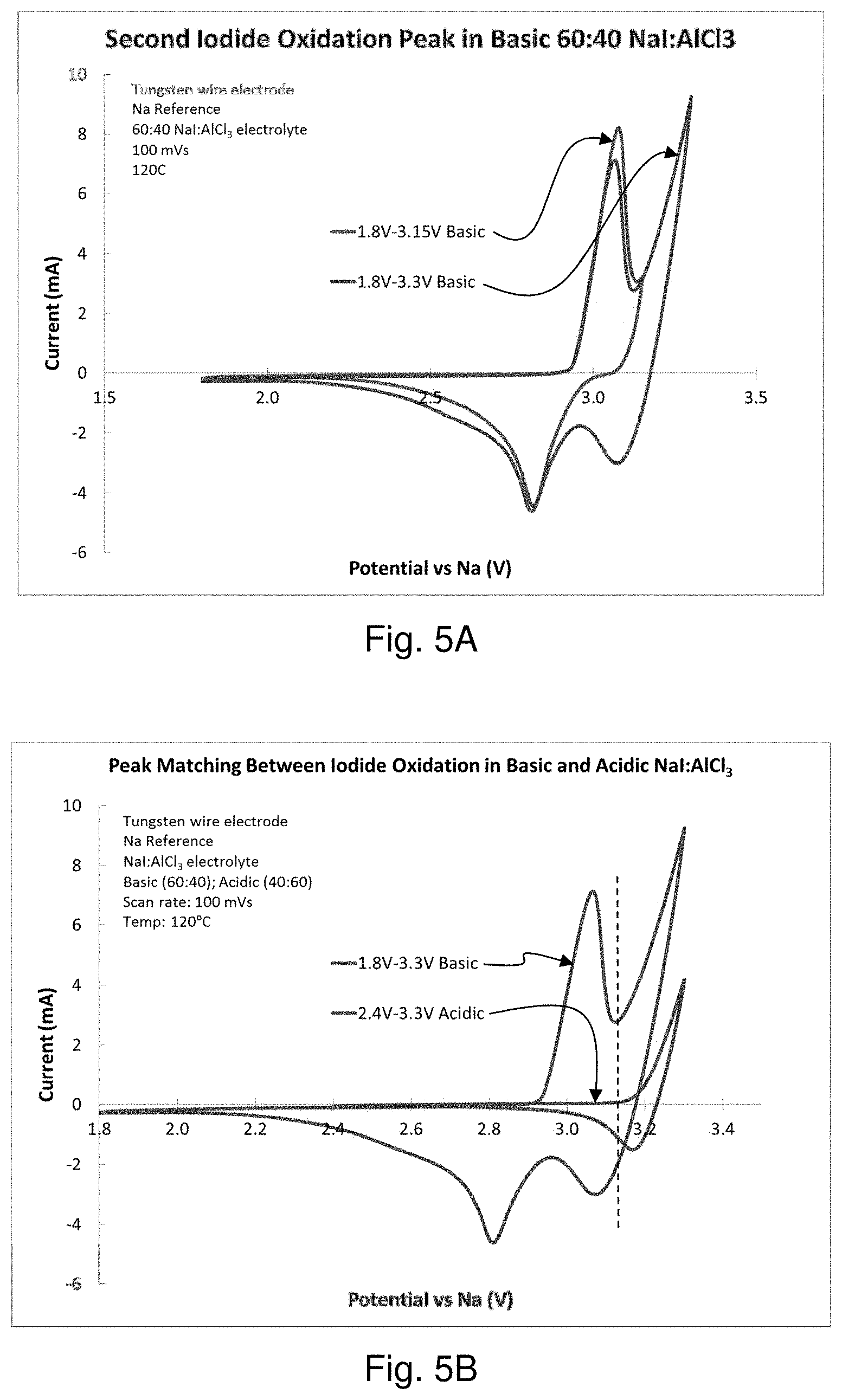
FIGS. 5A and 5B are graphs comparing the oxidation of iodide in a sodium-iodine secondary cell containing NaI in AlCl.sub.3 at basic and acidic ratios of NaI:AlCl.sub.3.
FIG. 6 is a graph of the current vs. voltage for the operation of the symmetrical cells described in Example 3.
DETAILED DESCRIPTION
Reference throughout this specification to "one embodiment," "an embodiment," or similar language means that a particular feature, structure, or characteristic described in connection with the embodiment is included in at least one embodiment of the present invention. Thus, appearances of the phrases "in one embodiment," "in an embodiment," "in another embodiment," and similar language throughout this specification may, but do not necessarily, all refer to the same embodiment. Additionally, while the following description refers to several embodiments and examples of the various components and aspects of the described invention, all of the described embodiments and examples are to be considered, in all respects, as illustrative only and not as being limiting in any manner.
Furthermore, the described features, structures, or characteristics of the invention may be combined in any suitable manner in one or more embodiments. In the following description, numerous specific details are provided, such as examples of suitable sodium-based negative electrodes, liquid positive electrode solutions, current collectors, sodium ion conductive electrolyte membranes, etc., to provide a thorough understanding of embodiments of the invention. One having ordinary skill in the relevant art will recognize, however, that the invention may be practiced without one or more of the specific details, or with other methods, components, materials, and so forth. In other embodiments, well-known structures, materials, or operations are not shown or described in detail to avoid obscuring aspects of the invention.
As stated above, secondary cells can be discharged and recharged and this specification describes cell arrangements and methods for both states. Although the term "recharging" in its various forms implies a second charging, one of skill in the art will understand that discussions regarding recharging would be valid for, and applicable to, the first or initial charge, and vice versa. Thus, for the purposes of this specification, the terms "recharge," "recharged," and "rechargeable" shall be interchangeable with the terms "charge," "charged," and "chargeable," respectively.
The present embodiments provide a sodium-halogen secondary cell, which includes a molten or solid state sodium negative electrode and a sodium halide positive electrode disposed in a molten positive electrolyte that comprises one or more haloaluminate salts. In some disclosed embodiments, the secondary cell utilizes a molten eutectic mixture of sodium haloaluminate salts having a relatively low melting point. Although the described cell can comprise any suitable component, FIG. 1 shows a representative embodiment in which the sodium secondary cell 10 comprises a negative electrode compartment 15 that includes a sodium metal negative electrode 20 and a positive electrode compartment 25 that comprises a sodium halide positive electrode. The positive electrode includes a current collector 30 disposed in a positive electrolyte 35 comprising one or more molten haloaluminate salts (AlCl.sub.3, AlBr.sub.3, and AlI.sub.3). A sodium ion conductive electrolyte membrane 40 separates the negative electrode from the positive electrode and positive electrolyte 35. The sodium ion conductive electrolyte membrane 40 separates a first terminal 45 from a second terminal 50. To provide a better understanding of the described cell 10, a brief description of how the cell functions is provided below. Following this discussion, each of the cell's components shown in FIG. 1 is discussed in more detail.
Turning now to the manner in which the sodium secondary cell 10 functions, the cell can function in virtually any suitable manner. In one example, FIG. 1 illustrates that as the cell 10 is discharged and electrons (e.sup.-) flow from the negative electrode 20 (e.g., via the first terminal 45), sodium is oxidized from the negative electrode 20 to form sodium ions (Na.sup.+). FIG. 1 shows that these sodium ions are respectively transported from the sodium negative electrode 20, through the sodium ion conductive membrane 40, and to the positive electrolyte 35.
In a contrasting example, FIG. 2 shows that as the secondary cell 10 is recharged and electrons (e.sup.-) flow into the sodium negative electrode 20 from an external power source (not shown), such as a recharger, the chemical reactions that occurred when the cell 10 was discharged (as shown in FIG. 1) are reversed. Specifically, FIG. 2 shows that as the cell 10 is recharged, sodium ions (Na.sup.+) are respectively transported from the positive electrolyte 35, through the electrolyte membrane 40, and to the negative electrode 20, where the sodium ions are reduced to form sodium metal (Na).
Referring now to the various components of the cell 10, the cell, as mentioned above, can comprise a negative electrode compartment 15 and a positive electrode compartment 25. In this regard, the two compartments can be any suitable shape and have any other suitable characteristic that allows the cell 10 to function as intended. By way of example, the negative electrode and the positive electrode compartments can be tubular, rectangular, or be any other suitable shape. Furthermore, the two compartments can have any suitable spatial relationship with respect to each other. For instance, while FIG. 2 shows that the negative electrode compartment 15 and the positive electrode compartment 25 can be adjacent to each other, in other embodiments (not shown), one compartment (e.g., the negative electrode compartment) is disposed, at least partially, in the other compartment (e.g., the positive electrode compartment), while the contents of the two compartments remain separated by the electrolyte membrane 40 and any other compartmental walls.
With respect to the negative electrode 20, the cell 10 can comprise any suitable sodium negative electrode 20 that allows the cell 10 to function (e.g., be discharged and recharged) as intended. Some examples of suitable sodium negative electrode materials include, but are not limited to, a sodium sample that is substantially pure and a sodium alloy comprising any other suitable sodium-containing negative electrode material. In certain embodiments, however, the negative electrode comprises or consists of an amount of sodium that is substantially pure. In such embodiments, because the melting point of pure sodium is around 98.degree. C., the sodium negative electrode will become molten above that temperature.
With respect to the positive current collector 30, the positive electrode compartment 25 can comprise any suitable positive electrode that allows the cell to be charged and discharged as intended. For instance, the positive electrode can comprise virtually any current collector 30 in combination with a halogen, shown generically as "X" in FIGS. 1 and 2, in a positive electrolyte 35 comprising one or more sodium haloaluminate salts. The current collector 30 can be disposed in any suitable location in the positive electrode compartment 25 that allows the cell 10 to function as intended.
With respect to the current collector 30, the cell 10 can comprise any suitable current collector that allows the cell to be charged and discharged as intended. For instance, the current collector can comprise virtually any current collector configuration that has been successfully used in a sodium-based rechargeable battery system. In some embodiments, the current collector comprises at least one of wires, felts, foils, plates, parallel plates, tubes, meshes, mesh screens, foams, and/or other suitable current collector configuration. It will be appreciated by those of skill in the art that the foam may include, without limitation, metal foams and carbon foams. Indeed, in some embodiments, the current collector comprises a configuration having a relatively large surface area which may include one or more mesh screens and metal foams.
The current collector 30 can comprise any suitable material that allows the cell 10 to function as intended. In this regard, some non-limiting examples of suitable current collector materials include tungsten, stainless steel, carbon, molybdenum, titanium, platinum, copper, nickel, zinc, a sodium intercalation material (e.g., Na.sub.xMnO.sub.2, etc.), nickel foam, nickel, a sulfur composite, a sulfur halide (e.g., sulfuric chloride), and/or another suitable material. Furthermore, these materials may coexist or exist in combinations. In some embodiments, however, the current collector comprises tungsten, carbon, molybdenum, titanium.
In some non-limiting embodiments, the reactions that may occur at the negative electrode 20, the positive electrode/current collector 30, and the overall reaction as the cell 10 is discharged may occur in at least two steps. These two potential reactions are shown below and designated Battery Chemistry 1 (shown schematically in FIG. 3A for battery recharge) and Battery Chemistry 2 (shown schematically in FIG. 3B for battery recharge). It has been observed that these reactions may be individual steps of a multi-step reaction, or depending upon the battery conditions, one step may be favored over another step. Negative electrode NaNa.sup.++1e.sup.- Positive electrode X.sub.3.sup.-+2e.sup.-3X.sup.- (Battery Chemistry 1) Positive electrode 3X.sub.2+2e.sup.-2X.sub.3.sup.- (Battery Chemistry 2) Overall 2Na+X.sub.3.sup.-2Na.sup.++3X.sup.- (Battery Chemistry 1) Overall 2Na+3X.sub.22Na.sup.++2X.sub.3.sup.- (Battery Chemistry 2)
Where X comprises iodine, bromine, or chlorine.
Where X comprises iodine, the cell 10 may have the following chemical reactions and the following theoretical voltage (V vs. SHE (standard hydrogen electrode)) and theoretical specific energy (Wh/kg): Negative electrode NaNa.sup.++1e.sup.- (-2.71V) Positive electrode I.sub.3.sup.-+2e.sup.-3I.sup.- (0.29V, Chemistry 1) Positive electrode 3I.sub.2+2e.sup.-2I.sub.3.sup.- (0.74V, Chemistry 2) Overall 2Na+I.sub.3.sup.-2Na.sup.++3I.sup.- (2.8V, Chemistry 1) (388 Wh/kg) Overall 2Na+3I.sub.22Na.sup.++2I.sub.3.sup.- (3.25V, Chemistry 2) (193 Wh/kg)
Where X is iodine, the charging reactions at the positive electrode may occur in two steps: 1) iodide to triiodide and 2) triiodide to iodine. Similarly, discharging reactions at the positive electrode may occur in two steps: 1) iodine to triiodide and 2) triiodide to iodide. Alternatively, the charging and discharging reactions may occur using the combination of reaction chemistries above.
Where X is bromine, the cell 10 may have the following chemical reactions and the following theoretical voltage (V vs. SHE) and theoretical specific energy (Wh/kg): Negative electrode NaNa.sup.++1e.sup.- (-2.71V) Positive electrode Br.sub.3.sup.-+2e.sup.-3Br.sup.- (0.82V, Chemistry 1) Positive electrode 3Br.sub.2+2e.sup.-2Br.sub.3.sup.- (1.04V, Chemistry 2) Overall 2Na+Br.sub.3.sup.-2Na.sup.++3Br.sup.- (3.53V, Chemistry 1) (658 Wh/kg) Overall 2Na+3Br.sub.22Na.sup.++2Br.sub.3.sup.- (3.75V, Chemistry 2) (329 Wh/kg)
The charging reactions at the positive electrode may occur in two steps: 1) bromide to tribromide and 2) tribromide to bromine. Similarly, discharging reactions at the positive electrode may occur in two steps: 1) bromine to tribromide and 2) tribromide to bromide. Alternatively, the charging and discharging reactions may occur using the combination of reaction chemistries above.
It will be appreciated by those of skill in the art that an alternative positive electrode chemistry may include: Positive electrode X.sub.2+2e.sup.-2X.sup.- (Battery Chemistry 3)
With an overall battery chemistry of: Overall 2Na+X.sub.22Na.sup.++2X.sup.- (Battery Chemistry 3)
With regards now to the sodium ion conductive electrolyte membrane 40, the membrane can comprise any suitable material that selectively transports sodium ions and permits the cell 10 to function with a positive electrolyte 35. In some embodiments, the electrolyte membrane comprises a NaSICON-type (sodium Super Ion CONductive) material. Where the electrolyte membrane comprises a NaSICON-type material, the NaSICON-type material may comprise any known or novel NaSICON-type material that is suitable for use with the described cell 10. Some suitable examples of NaSICON-type compositions include, but are not limited to, Na.sub.3Zr.sub.2Si.sub.2PO.sub.12, Na.sub.1+xSi.sub.xZr.sub.2P.sub.3-xO.sub.12 (where x is between about 1.6 and about 2.4), Y-doped NaSICON (Na.sub.1+x+yZr.sub.2-yY.sub.ySi.sub.xP.sub.3-xO.sub.12, Na.sub.1+xZr.sub.2-yY.sub.ySi.sub.xP.sub.3-xO.sub.12-y (where x=2, y=0.12)), Na.sub.1-xZr.sub.2Si.sub.xP.sub.3-xO.sub.12 (where x is between about 0 and about 3, and in some cases between about 2 and about 2.5), and Fe-doped NaSICON (Na.sub.3Zr.sub.2/.sub.3Fe.sub.4/.sub.3P.sub.3O.sub.12). Indeed, in certain embodiments, the NaSICON-type membrane comprises Na.sub.3Si.sub.2Zr.sub.2PO.sub.12. In other embodiments, the NaSICON-type membrane comprises one or more NaSELECT.RTM. materials, produced by Ceramatec, Inc. in Salt Lake City, Utah.
The positive electrode comprises NaX, where X is a halogen selected from Cl, Br and I. The positive electrode is preferably NaI.
The positive electrode is disposed in a molten salt positive electrolyte comprising AlX.sub.3. NaX and AlX.sub.3 may combine to form NaAlX.sub.4 as follows: NaX+AlX.sub.3AlX.sub.4
In some embodiments, the positive electrode is combined with a mixture of at least two AlX.sub.3 salts. The combination of positive electrode and positive electrolyte can be represented by the general formula NaAlX'.sub.4-.delta.X''.sub..delta., where 0<.delta.<4, wherein X' and X'' are different halogens selected from Cl, Br and I.
The mixed molten salt positive electrolyte comprises at least two salts of the general formula NaAlX'.sub.4 and NaAlX''.sub.4 at various molar ratios, wherein X' and X'' are different halogens selected from Cl, Br and I. In one non-limiting embodiment, the molar ratio of NaAlX'.sub.4 to NaAlX''.sub.4 is in the range of 9:1 to 1:9 with corresponding .delta. values of 0.4 to 3.6.
The positive electrode comprises additional NaX or a mixture of NaX compounds added in a molar ratio to the mixed molten salt positive electrolyte ranging from 1:1 to 3:1 of NaX:NaAlX'.sub.4-.delta.X''.sub..delta.. The excess NaX renders the positive electrolyte highly basic. At cell operating temperatures, the positive electrode and mixed molten salt positive electrolyte is a molten liquid or a two phase mixture wherein the mixed molten salt positive electrolyte is predominantly a liquid phase and the additional NaX or mixture of NaX compounds is a solid phase.
The following Table 1 illustrates some non-limiting combinations of NaX and AlX.sub.3 to form NaAlX.sub.4.
TABLE-US-00001 TABLE 1 AlX.sub.3 NaX AlCl.sub.3 AlBr.sub.3 AlI.sub.3 NaCl NaAlCl.sub.4 NaAlBr.sub.3Cl NaAlI.sub.3Cl NaBr NaAlCl.sub.3Br NaAlBr.sub.4 NaAlI.sub.3Br NaI NaAlCl.sub.3I NaAlBr.sub.3I NaAlI.sub.4
In other embodiments, the positive electrode is disposed in a mixed molten salt positive electrolyte comprising at least three salts that can be represented by the formula NaAlX'.sub.4-.delta.-.omega.X''.sub..delta.X'''.sub..omega., where X', X'' and X''' are three different halogens selected from Cl, Br, and I, where 0<.delta.<4, 0<.omega.<4, and 0<.delta.+.omega.<4. The mixed molten salt positive electrolyte comprises NaAlCl.sub.4, NaAlBr.sub.4, and NaAlI.sub.4, at various molar ratios.
In some embodiments, the positive electrolyte 35 also comprises one or more halogens and/or halides. In this regard, the halogens and halides, as well polyhalides and/or metal halides that form therefrom (e.g., where the current collector 30 comprises a metal, such as copper, nickel, zinc, etc. (as discussed below)) can perform any suitable function, including, without limitation, acting as the positive electrode as the cell 10 operates. Some examples of suitable halogens include bromine, iodine, and chlorine. Similarly, some examples of suitable halides include bromide ions, polybromide ions, iodide ions, polyiodide ions, chloride ions, and polychloride ions. While the halogens/halides can be introduced into the positive electrode solution in any suitable manner, in some embodiments, they are added as NaX, wherein X is selected from Br, I, Cl, etc.
With reference now to the terminals 45 and 50, the cell 10 can comprise any suitable terminals that are capable of electrically connecting the cell with an external circuit (not shown), including without limitation, to one or more cells. In this regard, the terminals can comprise any suitable material, be of any suitable shape, and be of any suitable size.
In addition to the aforementioned components, the cell 10 can optionally comprise any other suitable component. By way of non-limiting illustration FIGS. 1 and 2 show an embodiment in which the cell 10 comprises a heat management system 55, 60. Independent heat management systems may be associated with the negative electrode and positive electrode compartments. Alternatively, a single heat management system may be disposed in only one compartment or to the exterior of the cell 10 generally. In such embodiments, the cell can comprise any suitable type of heat management system that is capable of maintaining the cell within a suitable operating temperature range. Some examples of such heat management systems include, but are not limited to, a heater, a cooler, one or more temperature sensors, and appropriate temperature control circuitry.
The described cell 10 may function at any suitable operating temperature. In other words, as the cell is discharged and/or recharged, the sodium negative electrode and the positive electrolyte may have any suitable temperature. The negative and positive electrode compartments may operate at the same or different temperatures. Indeed, in some embodiments, the cell functions at an intermediate operating temperature in the range from about 80.degree. C. to about 210.degree. C. In other embodiments, the cell may function at an intermediate operating temperature in the range from about 110.degree. C. to about 180.degree. C. In yet another embodiment, the operating temperature of the cell in the range of about 150.degree. C. to about 170.degree. C.
The following examples are given to illustrate various embodiments within, and aspects of, the scope of the present invention. These are given by way of example only, and it is understood that the following examples are not comprehensive or exhaustive of the many types of embodiments of the present invention that can be prepared in accordance with the present invention.
Example 1
The conductivity of NaI in a molten salt positive electrolyte AlCl.sub.3 was compared to the conductivity of NaI in an organic solvent solution that included N-methyl formamide. The molten salt positive electrolyte had a general formula of NaAl.sub.xI.sub.yCl.sub.z. The conductivity of NaI in a molten salt positive electrolyte was approximately three times the conductivity of the organic solvent-based electrolyte at 120.degree. C., as shown in FIG. 4. Cells utilizing a molten salt positive electrolyte will be more energy dense due to higher molarity of NaI. Furthermore, cells utilizing a molten salt positive electrolyte are safer than organic solvent based positive electrolyte solutions because if molten sodium happens to contact the molten salt positive electrolyte, the chemical reaction would only produce non-flammable salts.
Example 2
A sodium-iodine secondary cell was prepared as described herein containing sodium iodide in molten AlCl.sub.3 in a 60:40 NaI:AlCl.sub.3 ratio (a "basic" electrolyte). Tungsten wire was used as the positive current collector. NaSICON was used to separate a molten sodium negative electrode from the positive electrode/positive electrolyte. The oxidation of iodide was measured and found to produce two oxidation peaks, consistent with Battery Chemistry 1 and Battery Chemistry 2, described herein. Experimental results are shown in FIG. 5A. The oxidation peaks were found to be reversible. Additional tests were performed using an "acidic" electrolyte comprising sodium iodide in molten AlCl.sub.3 in a 40:60 NaI:AlCl.sub.3 ratio. Experimental results are shown in FIG. 5B. The results suggest that the second oxidation peak in the basic electrolyte occurs at a similar potential as the first iodide oxidation peak in the acidic electrolyte. The reduction peak in acidic electrolyte occurs at a higher potential. This suggests that whether the electrolyte is acidic or basic affects the potential of I.sub.2 generation.
Example 3
Three symmetrical sodium-iodine secondary cells were prepared to test the reversibility of the oxidation/reduction reactions that occur in the positive electrode/positive electrolyte. The symmetrical cells were prepared as set forth in Table 2, below:
TABLE-US-00002 TABLE 2 Electrode Electrolyte Cell Outside of tube Inside of tube Outside of Tube Inside of Tube Symmetrical Cell 1 Graphite felt Graphite felt 1M I.sub.2 in 51:49 mol % 1M I.sub.2 in 51:49 mol % with tungsten with tungsten NaI:AlCl.sub.3 NaI:AlCl.sub.3 wire wire Symmetrical Cell 2 0.93 g Tungsten wire 60:40 mol % NaI:AlCl.sub.3 0.02475 g I.sub.2 in NaI/0.93 g with graphite 51:49 mol % NaI:AlCl.sub.3 C/PTFE felt around tungsten mesh Symmetrical Cell 3 Graphite felt 0.25'' Carbon 60:40 mol % NaI:AlCl.sub.3 50:50 mol % NaI:AlCl.sub.3 with tungsten Rod wire
The symmetrical cells were operated as set forth in Table 3, below:
TABLE-US-00003 TABLE 3 Operating Range Upper Lower Current Temper- EIS Voltage Voltage Density ature Ohmic System Limit Limit (mA/ Cell (.degree. C.) (.OMEGA.) (.OMEGA.) (V) (V) cm.sup.2) Symmetrical 125 2.17 5.19 0.5 -0.5 91 Cell 1 Symmetrical 125 3.60 16.40 0.5 -0.5 72 Cell 2 Symmetrical 125 5.00 6.70 0.15 -0.15 20 Cell 3
A graph of the current vs. voltage for the operation of the symmetrical cells is shown in FIG. 6. Because there is little or no hysteresis shown in FIG. 6, it may be concluded that the oxidation/reduction reactions that occur in the positive electrode/positive electrolyte are highly reversible.
Embodiments of the present invention may be embodied in other specific forms without departing from its spirit or essential characteristics. The described embodiments and examples are to be considered in all respects only as illustrative and not as restrictive. The scope of the invention is, therefore, indicated by the appended claims rather than by the foregoing description. All changes that come within the meaning and range of equivalency of the claims are to be embraced within their scope.
* * * * *
D00000
D00001
D00002
D00003
D00004
D00005
P00001
XML
uspto.report is an independent third-party trademark research tool that is not affiliated, endorsed, or sponsored by the United States Patent and Trademark Office (USPTO) or any other governmental organization. The information provided by uspto.report is based on publicly available data at the time of writing and is intended for informational purposes only.
While we strive to provide accurate and up-to-date information, we do not guarantee the accuracy, completeness, reliability, or suitability of the information displayed on this site. The use of this site is at your own risk. Any reliance you place on such information is therefore strictly at your own risk.
All official trademark data, including owner information, should be verified by visiting the official USPTO website at www.uspto.gov. This site is not intended to replace professional legal advice and should not be used as a substitute for consulting with a legal professional who is knowledgeable about trademark law.