Coiled capacitor
Robinson , et al. December 1, 2
U.S. patent number 10,854,386 [Application Number 16/854,031] was granted by the patent office on 2020-12-01 for coiled capacitor. This patent grant is currently assigned to CAPACITOR SCIENCES INCORPORATED. The grantee listed for this patent is CAPACITOR SCIENCES INCORPORATED. Invention is credited to Paul Furuta, Pavel Ivan Lazarev, Matthew R. Robinson.


View All Diagrams
| United States Patent | 10,854,386 |
| Robinson , et al. | December 1, 2020 |
Coiled capacitor
Abstract
The present disclosure provides a coiled capacitor comprising a coil formed by a flexible multilayered tape, and a first terminating electrode and a second terminating electrode which are located on butts of the coil. The flexible multilayered tape contains the following sequence of layers: first metal layer, a layer of a plastic, second metal layer, a layer of energy storage material. The first metal layer forms ohmic contact with the first terminating electrode and the second metal layer forms ohmic contact with the second terminating electrode. The energy storage material comprises material selected from the list comprising rylene fragments, doped oligoaniline and p-oligo-phenylene, supramolecular structures, colloidal composite with dispersion (suspension) of electro-conductive anisometric particles in an insulator matrix, material comprises a surfactant.
| Inventors: | Robinson; Matthew R. (San Francisco, CA), Furuta; Paul (Sunnyvale, CA), Lazarev; Pavel Ivan (Palo Alto, CA) | ||||||||||
|---|---|---|---|---|---|---|---|---|---|---|---|
| Applicant: |
|
||||||||||
| Assignee: | CAPACITOR SCIENCES INCORPORATED
(Menlo Park, CA) |
||||||||||
| Family ID: | 1000005218784 | ||||||||||
| Appl. No.: | 16/854,031 | ||||||||||
| Filed: | April 21, 2020 |
Prior Publication Data
| Document Identifier | Publication Date | |
|---|---|---|
| US 20200251281 A1 | Aug 6, 2020 | |
Related U.S. Patent Documents
| Application Number | Filing Date | Patent Number | Issue Date | ||
|---|---|---|---|---|---|
| 15943342 | Apr 2, 2018 | 10672561 | |||
| 14752600 | Jun 26, 2015 | 9941051 | |||
| Current U.S. Class: | 1/1 |
| Current CPC Class: | H01G 4/228 (20130101); H01G 4/18 (20130101); H01G 4/32 (20130101); H01G 4/012 (20130101); H01G 4/015 (20130101); Y02T 10/70 (20130101) |
| Current International Class: | H01G 4/18 (20060101); H01G 4/32 (20060101); H01G 4/015 (20060101); H01G 4/012 (20060101); H01G 4/228 (20060101) |
References Cited [Referenced By]
U.S. Patent Documents
| 3407394 | October 1968 | Hartke |
| 4694377 | September 1987 | MacDougall et al. |
| 4702562 | October 1987 | Scheuble et al. |
| 4894186 | January 1990 | Gordon et al. |
| 5141837 | August 1992 | Nguyen et al. |
| 5187639 | February 1993 | Ogawa et al. |
| 5248774 | September 1993 | Dietz et al. |
| 5312896 | May 1994 | Bhardwaj et al. |
| 5384521 | January 1995 | Coe |
| 5395556 | March 1995 | Drost et al. |
| 5466807 | November 1995 | Dietz et al. |
| 5514799 | May 1996 | Varanasi et al. |
| 5581437 | December 1996 | Sebilotte et al. |
| 5583359 | December 1996 | Ng et al. |
| 5679763 | October 1997 | Jen et al. |
| 5739296 | April 1998 | Gvon et al. |
| 5742471 | April 1998 | Barbee et al. |
| 5840906 | November 1998 | Zoltewicz et al. |
| 5880951 | March 1999 | Visco et al. |
| 6025094 | February 2000 | Visco et al. |
| 6049428 | April 2000 | Khan et al. |
| 6174394 | January 2001 | Gvon et al. |
| 6282081 | August 2001 | Takabayashi et al. |
| 6294593 | September 2001 | Jeng et al. |
| 6341056 | January 2002 | Allman et al. |
| 6391104 | May 2002 | Schulz |
| 6426861 | July 2002 | Munshi |
| 6501093 | December 2002 | Marks |
| 6583284 | June 2003 | Sidorenko et al. |
| 6617830 | September 2003 | Nozu et al. |
| 6798642 | September 2004 | Decker et al. |
| 7025900 | April 2006 | Sidorenko et al. |
| 7026019 | April 2006 | Dutova et al. |
| 7033406 | April 2006 | Weir et al. |
| 7045177 | May 2006 | Dutova et al. |
| 7160485 | May 2007 | Nazarov et al. |
| 7211824 | May 2007 | Lazarev |
| 7460352 | December 2008 | Jamison et al. |
| 7466536 | December 2008 | Weir et al. |
| 7498689 | March 2009 | Mitani et al. |
| 7579709 | August 2009 | Goetz et al. |
| 7625497 | December 2009 | Iverson et al. |
| 7750505 | July 2010 | Ichikawa |
| 7795431 | September 2010 | Pschirer et al. |
| 7808771 | October 2010 | Nguyen et al. |
| 7837902 | November 2010 | Hsu et al. |
| 7888505 | February 2011 | Doutova et al. |
| 7893265 | February 2011 | Facchetti et al. |
| 7910736 | March 2011 | Koenemann et al. |
| 7947199 | May 2011 | Wessling |
| 8143853 | March 2012 | Jestin et al. |
| 8222074 | July 2012 | Lazarev |
| 8231809 | July 2012 | Pschirer et al. |
| 8236998 | August 2012 | Nagata et al. |
| 8344142 | January 2013 | Marder et al. |
| 8372527 | February 2013 | Morishita et al. |
| 8404844 | March 2013 | Kastler et al. |
| 8527126 | September 2013 | Yamamoto et al. |
| 8552179 | October 2013 | Lazarev |
| 8818601 | August 2014 | V et al. |
| 8895118 | November 2014 | Geivandov et al. |
| 8929054 | January 2015 | Felten et al. |
| 8938160 | January 2015 | Wang |
| 9056676 | June 2015 | Wang |
| 9293260 | March 2016 | Schmid et al. |
| 9589727 | March 2017 | Lazarev |
| 9733406 | August 2017 | Doutova et al. |
| 9941051 | April 2018 | Robinson |
| 10672561 | June 2020 | Robinson |
| 2002/0027220 | March 2002 | Wang et al. |
| 2002/0048140 | April 2002 | Gallay et al. |
| 2003/0026063 | February 2003 | Munshi |
| 2003/0102502 | June 2003 | Togashi |
| 2003/0103319 | June 2003 | Kumar et al. |
| 2003/0142461 | July 2003 | Decker et al. |
| 2003/0219647 | November 2003 | Wariishi |
| 2003/0232153 | December 2003 | Kazarov et al. |
| 2004/0173873 | September 2004 | Kumar et al. |
| 2004/0222413 | November 2004 | Hsu et al. |
| 2005/0118083 | June 2005 | Tabuchi |
| 2005/0146671 | July 2005 | Khavrounyak et al. |
| 2006/0120014 | June 2006 | Nakamura et al. |
| 2006/0120020 | June 2006 | Dowgiallo |
| 2007/0001258 | January 2007 | Aihara |
| 2007/0108940 | May 2007 | Sainomoto et al. |
| 2007/0159767 | July 2007 | Jamison et al. |
| 2008/0002329 | January 2008 | Pohm et al. |
| 2008/0150484 | June 2008 | Kimball et al. |
| 2008/0266750 | October 2008 | Wu et al. |
| 2008/0283283 | November 2008 | Abe et al. |
| 2009/0034073 | February 2009 | Lazarev |
| 2009/0040685 | February 2009 | Hierner et al. |
| 2009/0184355 | July 2009 | Brederlow et al. |
| 2009/0191394 | July 2009 | Lazarev et al. |
| 2010/0038629 | February 2010 | Lazarev |
| 2010/0085521 | April 2010 | Kasianova et al. |
| 2010/0178728 | July 2010 | Zheng et al. |
| 2010/0183919 | July 2010 | Holme et al. |
| 2010/0190015 | July 2010 | Kasianova |
| 2010/0193777 | August 2010 | Takahashi et al. |
| 2010/0214719 | August 2010 | Kim et al. |
| 2010/0233491 | September 2010 | Nokel et al. |
| 2010/0255381 | October 2010 | Holme et al. |
| 2010/0269731 | October 2010 | Jespersen et al. |
| 2010/0279122 | November 2010 | Nokel et al. |
| 2010/0300960 | December 2010 | Allers et al. |
| 2010/0309606 | December 2010 | Alters et al. |
| 2010/0309696 | December 2010 | Guillot et al. |
| 2010/0315043 | December 2010 | Chau |
| 2011/0006393 | January 2011 | Cui |
| 2011/0042649 | February 2011 | Duvall et al. |
| 2011/0064892 | March 2011 | Nokel et al. |
| 2011/0079733 | April 2011 | Langhals et al. |
| 2011/0079773 | April 2011 | Wasieliewski et al. |
| 2011/0110015 | May 2011 | Zhang et al. |
| 2011/0228442 | September 2011 | Zhang et al. |
| 2012/0008251 | January 2012 | Yu et al. |
| 2012/0033342 | February 2012 | Ito et al. |
| 2012/0053288 | March 2012 | Morishita et al. |
| 2012/0056600 | March 2012 | Nevin |
| 2012/0113380 | May 2012 | Geivandov et al. |
| 2012/0122274 | May 2012 | Lazarev |
| 2012/0244330 | September 2012 | Sun et al. |
| 2012/0268862 | October 2012 | Song et al. |
| 2012/0274145 | November 2012 | Taddeo |
| 2012/0302489 | November 2012 | Rodrigues et al. |
| 2013/0056720 | March 2013 | Kim et al. |
| 2013/0187475 | July 2013 | Vendik et al. |
| 2013/0194716 | August 2013 | Holme et al. |
| 2013/0215535 | August 2013 | Bellomo |
| 2013/0314839 | November 2013 | Terashima et al. |
| 2013/0342967 | December 2013 | Lai et al. |
| 2014/0035100 | February 2014 | Cho |
| 2014/0036410 | February 2014 | Okamatsu et al. |
| 2014/0098458 | April 2014 | Almadhoun et al. |
| 2014/0158340 | June 2014 | Dixler et al. |
| 2014/0169104 | June 2014 | Kan et al. |
| 2014/0185260 | July 2014 | Chen et al. |
| 2014/0268490 | September 2014 | Tsai et al. |
| 2014/0347787 | November 2014 | Fathi et al. |
| 2015/0008735 | January 2015 | Mizoguchi |
| 2015/0158392 | June 2015 | Zhao |
| 2015/0162131 | June 2015 | Felten et al. |
| 2015/0249401 | September 2015 | Eriksen et al. |
| 2015/0302990 | October 2015 | Ghosh et al. |
| 2016/0020026 | January 2016 | Lazarev |
| 2016/0020027 | January 2016 | Lazarev |
| 2016/0254092 | September 2016 | Lazarev et al. |
| 2016/0314901 | October 2016 | Lazarev |
| 2016/0340368 | November 2016 | Lazarev |
| 2016/0379757 | December 2016 | Robinson et al. |
| 2017/0117097 | April 2017 | Furuta et al. |
| 2017/0233528 | August 2017 | Sharp et al. |
| 2017/0236648 | August 2017 | Lazarev et al. |
| 2017/0237271 | August 2017 | Kelly-Morgan et al. |
| 2017/0237274 | August 2017 | Lazarev et al. |
| 2017/0287637 | October 2017 | Lazarev et al. |
| 2017/0287638 | October 2017 | Lazarev et al. |
| 2074848 | Feb 1998 | CA | |||
| 100449661 | Jan 2009 | CN | |||
| 102426918 | Apr 2012 | CN | |||
| 103261370 | Aug 2013 | CN | |||
| 203118781 | Aug 2013 | CN | |||
| 203377785 | Jan 2014 | CN | |||
| 103755703 | Apr 2014 | CN | |||
| 103986224 | Aug 2014 | CN | |||
| 10203918 | Aug 2003 | DE | |||
| 102010012949 | Sep 2011 | DE | |||
| 102011101304 | Nov 2012 | DE | |||
| 102012016438 | Feb 2014 | DE | |||
| 0493716 | Jul 1992 | EP | |||
| D493716 | Jul 1992 | EP | |||
| 0585999 | Mar 1994 | EP | |||
| 0602654 | Jun 1994 | EP | |||
| 0729056 | Aug 1996 | EP | |||
| 0791849 | Aug 1997 | EP | |||
| 1158320 | Nov 2001 | EP | |||
| 0986080 | Jan 2004 | EP | |||
| 0865142 | May 2008 | EP | |||
| 2062944 | May 2009 | EP | |||
| 2260035 | Dec 2010 | EP | |||
| 2415543 | Feb 2012 | EP | |||
| 2667392 | Nov 2013 | EP | |||
| 1486590 | Dec 2013 | EP | |||
| 2759480 | Jul 2014 | EP | |||
| 547853 | Sep 1942 | GB | |||
| 923148 | Apr 1963 | GB | |||
| 2084585 | Nov 1983 | GB | |||
| S61002314 | Jan 1986 | JP | |||
| S6386731 | Apr 1988 | JP | |||
| H03253014 | Nov 1991 | JP | |||
| 2786298 | Aug 1998 | JP | |||
| 2000100484 | Apr 2000 | JP | |||
| 2005045266 | Feb 2005 | JP | |||
| 2006011431 | Jan 2006 | JP | |||
| 2007013105 | Jan 2007 | JP | |||
| 2007287829 | Nov 2007 | JP | |||
| 2010106225 | May 2010 | JP | |||
| 2010160989 | Jul 2010 | JP | |||
| 2011029442 | Feb 2011 | JP | |||
| 2011061191 | Mar 2011 | JP | |||
| 2012041382 | Mar 2012 | JP | |||
| 2013247206 | Dec 2013 | JP | |||
| 2014139296 | Jul 2014 | JP | |||
| 2199450 | Feb 2003 | RU | |||
| 2512880 | Apr 2014 | RU | |||
| 1990009616 | Aug 1990 | WO | |||
| 0139305 | May 2001 | WO | |||
| 2002026774 | Apr 2002 | WO | |||
| 2002094942 | Apr 2003 | WO | |||
| 2007078916 | Jul 2007 | WO | |||
| 2008038047 | Apr 2008 | WO | |||
| 2009158553 | Dec 2009 | WO | |||
| 2011056903 | May 2011 | WO | |||
| 2012012672 | Jan 2012 | WO | |||
| 2012084536 | Jun 2012 | WO | |||
| 2012122312 | Sep 2012 | WO | |||
| 2012162500 | Nov 2012 | WO | |||
| 2013009772 | Jan 2013 | WO | |||
| 2013085467 | Jun 2013 | WO | |||
| 2014009686 | Jan 2014 | WO | |||
| 2015003725 | Jan 2015 | WO | |||
| 2015175522 | Nov 2015 | WO | |||
| 2015175558 | Nov 2015 | WO | |||
Other References
|
Notice of Allowance for U.S. Appl. No. 15/053,943, dated Aug. 14, 2017. cited by applicant . Notice of Allowance for U.S. Appl. No. 15/090,509, dated Jan. 24, 2018. cited by applicant . Notice of Allowance for U.S. Appl. No. 14/710,491, dated Oct. 24, 2016. cited by applicant . Office Action dated Dec. 13, 2017 for Taiwan Patent Application No. 106104499. cited by applicant . Office Action dated Dec. 13, 2017 for Taiwan Patent Application No. 106104500. cited by applicant . Office Action dated Jan. 25, 2018 for Chinese patent application No. 20158005146.4. cited by applicant . Office Action dated Oct. 19, 2017 for Taiwan patent Application No. 106104501. cited by applicant . Optical Society of America, Kuzyk et al, "Theory of Molecular Nonlinear Optics", pp. 5, 4-82, Department of Physics and Astronomy, Washington State University, Pullman, Washington 99164-2814, USA, Mar. 26, 2013. cited by applicant . Philosophical Transactions of the Royal Society, SIMON, "Charge storage mechanism in nanoporous carbons and its consequence for electrical double layer capacitors" pp. 3457-3467; Drexel University, Philadelphia, PA 19104, 2010. cited by applicant . Search Report and Written Opinion dated Feb. 7, 2018 for Singapore Patent Application No. 11201609435W. cited by applicant . Taiwan Office Action for TW Application No. 106104501, dated Oct. 19, 2017. cited by applicant . U.S. Appl. No. 14/719,072, to Pavel Ivan Lazarev, filed May 21, 2015. cited by applicant . U.S. Appl. No. 14/752,600, to Matthew R. Robinson, et al., filed Jun. 26, 2015. cited by applicant . U.S. Appl. No. 14/919,337, to Paul T. Furuta, et al., filed Oct. 21, 2015. cited by applicant . U.S. Appl. No. 14/931,757, to Pavel Ivan Lazarev, et al., filed Nov. 3, 2015. cited by applicant . U.S. Appl. No. 15/043,186, to Paul T. Furuta, et al., filed Feb. 12, 2016. cited by applicant . U.S. Appl. No. 15/043,209, to Paul T. Furuta, et al., filed Feb. 12, 2016. cited by applicant . U.S. Appl. No. 15/043,247, to Barry K Sharp, et al., filed Feb. 12, 2016. cited by applicant . U.S. Appl. No. 15/043,315, to Ian S.G. Kelly-Morgan, filed Feb. 12, 2014. cited by applicant . U.S. Appl. No. 15/043,315, to Ivan S.G. Kelley-Morgan, filed Feb. 12, 2016. cited by applicant . U.S. Appl. No. 15/053,943, to Pavel Ivan Lazarev, et al., filed Mar. 14, 2016. cited by applicant . U.S. Appl. No. 15/090,509, to Pavel Ivan Lazarev, et al., filed Mar. 4, 2016. cited by applicant . U.S. Appl. No. 62/121,328, to Pavel Ivan Lazarev et al., filed Feb. 26, 2015. cited by applicant . U.S. Appl. No. 62/294,949, to Pavel Ivan Lazarev, et al., filed Feb. 12, 2016. cited by applicant . U.S. Appl. No. 62/294,955, to Pavel Ivan Lazarev, et al., filed Feb. 12, 2016. cited by applicant . U.S. Appl. No. 62/294,964, to Pavel Ivan Lazarev, et al., filed Feb. 12, 2016. cited by applicant . U.S. Appl. No. 62/318,134, to Pavel Ivan Lazarev, et al., filed Mar. 4, 2016. cited by applicant . Updated Notice of Allowance for U.S. Appl. No. 14/710,480, dated Jan. 17, 2018. cited by applicant . Warmerdam, T. W. et al. "Discotic Liquid Crystals. Physical Parameters of some 2, 3, 7, 8, 12, 13-hexa(alkanoyloxy) truxenes: Observation of a Reentrant Isotropic Phase in a Pure Disk-like mesogen." Liquid Crystals (1988), vol. 3, No. 3, pp. 1087-1104. cited by applicant . International Search Report and Written Opinion dated Jun. 7, 2017 for International Application No. PCT/US2017/24589, to Pavel Ivan Lazarev, filed Jun. 7, 2017. cited by applicant . International Search Report and Written Opinion dated Oct. 20, 2016 International Application No. PCT/US2016/039395, to Matthew R. Robinson, et al., filed Jun. 24, 2016. cited by applicant . International Search Report and Written Opinion dated Sep. 1, 2016 for International Application No. PCT/US2016/033628, to Pavel Ivan Lazarev, filed Sep. 1, 2016. cited by applicant . International Union of Pure and Applied Chemistry Polymer Divison Stejskal et al., "Polyaniline: Thin Films and Colloidal Dispersions (IUPAC Technical Report)", vol. 77, No. 5, pp. 815-826, Russian Academy of Sciences, St. Petersburg 199004, Russia; 2005. cited by applicant . Isoda, Kyosuke et al. "Truxene-Based Columnar Liquid Crystals: Self-Assembled Structures and Electro-Active Properties." Chemistry--An Asian Journal (2009), vol. 4, No. 10, pp. 1619-1625. cited by applicant . JACS Articles, Kang et. al., "Ultralarge Hyperpolarizability Twisted .pi.-Electron System Electra-Optic Chromophores: Synthesis, Solid-State and Solution-Phase Structural Characteristics, Electronic Structures, Linear and Nonlinear Optical Properties, and Computational Studies", pp. 3267-3286; Perugia, Italy Feb. 20, 2007. cited by applicant . Johnson, Kieth E. "What's an Ionic Liquid?" The Electrochemical Society Interface, Published Spring 2007, pp. 38-41, Accessed Aug. 28, 2017. cited by applicant . Maddalena, Francesco "Why are Ionic Liquids, Liquids?" http://www.quora.com/why-are-ionic-liquids-liquids?, Published Jan 26, 2017, Accessed Aug. 28, 2017. cited by applicant . Manukian, BK. 216. IR.-spektroskopische Untersuchungen in der Imidazol-Reihe. Helvetica Chimica Acta. 1965, vol. 48, page. cited by applicant . Manukian, BK. 216. IR.-spektroskopische Untersuchungen in der Imidazol-Reihe. Helvetica Chimica Acta. 1965, vol. 18, p. 2001. cited by applicant . Nagabrahmandachari et al. "Synthesis and Spectral Analysis of Tin Tetracarboxylates and Phosphinates" Indian Journal of Chemistry--Section A, 1995, vol. 34A, pp. 658-660. cited by applicant . Ni, Hai-Lang et al. "Truxene Discotic Liquid Crystals with Two Different Ring Substituents: Synthesis, Metamorphosis and High Charged Carrier Mobility ." Liquid Crystals, vol. 40, No. 3, pp. 411-420. cited by applicant . Non-Final Action for U.S. Appl. No. 15/043,186, dated Feb. 14, 2018. cited by applicant . Non-Final Office Action dated Jun. 13, 2017 for U.S. Appl. No. 15/163,595. cited by applicant . Non-Final Office Action for U.S. Appl. No. 14/719,072, dated Aug. 2, 2017. cited by applicant . Non-Final Office Action for U.S. Appl. No. 15/043,247, dated Jun. 22, 2017. cited by applicant . Non-Final Office Action for U.S. Appl. No. 15/043,315, dated Dec. 26, 2017. cited by applicant . Non-Final Office Action for U.S. Appl. No. 15/053,943, dated Apr. 19, 2017. cited by applicant . Non-Final Office Action for U.S. Appl. No. 15/090,509, dated Jun. 22, 2017. cited by applicant . Non-Final Office Action for U.S. Appl. No. 15/163,595, dated Jan. 17, 2018. cited by applicant . Non-Final Office Action for U.S. Appl. No. 15/194,224, dated Sep. 27, 2017. cited by applicant . Non-Final Office Action for U.S. Appl. No. 14/710,480, dated May 8, 2017. cited by applicant . Non-Final Office Action for U.S. Appl. No. 14/752,600, dated Jan. 23, 2017. cited by applicant . Non-Final Office Action for U.S. Appl. No. 14/919,337, dated Jan. 4, 2017. cited by applicant . Non-Final Office Action for U.S. Appl. No. 15/043,186, dated Jun. 2, 2017. cited by applicant . Non-Final/Final Office Action for U.S. Appl. No. 15/043,247, dated Feb. 20, 2018. cited by applicant . Notice of Allowance for U.S. Appl. No. 14/710,480, dated Nov. 24, 2017. cited by applicant . Notice of Allowance for U.S. Appl. No. 14/710,480, dated Jan. 11, 2018. cited by applicant . Notice of Allowance for U.S. Appl. No. 14/710,480, dated Oct. 6, 2017. cited by applicant . Notice of Allowance for U.S. Appl. No. 14/719,072, dated Nov. 16, 2017. cited by applicant . Notice of Allowance for U.S. Appl. No. 14/752,600, dated Jul. 27, 2017. cited by applicant . Notice of Allowance for U.S. Appl. No. 14/919,337, dated Jul. 19, 2017. cited by applicant . Notice of Allowance for U.S. Appl. No. 14/919,337, dated Mar. 5, 2018. cited by applicant . Notice of Allowance for U.S. Appl. No. 14/919,337, Nov. 8, 2017. cited by applicant . Notice of Allowance for U.S. Appl. No. 14/931,757, dated Dec. 29, 2017. cited by applicant . Notice of Allowance for U.S. Appl. No. 14/931,757, dated Feb. 8, 2018. cited by applicant . Notice of Allowance for U.S. Appl. No. 14/931,757, dated Jul. 17, 2017. cited by applicant . Notice of Allowance for U.S. Appl. No. 14/931,757, dated Oct. 31, 2017. cited by applicant . Center for Dielectric Studies, Janosik, et al., "Ultra-High Energy Density Capacitors Through Improved Glass Technology", pp. 1-5 Center for Dielectric Studies Penn State University, dated 2004. cited by applicant . Congressional Research Service, Paul W. Parfomak, "Energy Storage for Power Grids and Electric Transportation: A Technology Assessment", pp. 87-94; Members and Committees of Congress; Mar. 27, 2012. cited by applicant . Co-Pending U.S. Appl. No. 15/194,224, to Lazarev et al., filed Jun. 27, 2016. cited by applicant . Co-Pending U.S. Appl. No. 15/368,171, to Lazarev et al., filed Dec. 2, 2016. cited by applicant . Co-Pending U.S. Appl. No. 15/430,307, to Lazarev et al, filed Feb. 10, 2017. cited by applicant . Co-Pending U.S. Appl. No. 15/449,587, to Lazarev et al., filed Mar. 3, 2017. cited by applicant . Co-Pending U.S. Appl. No. 15/675,614, to Kelly-Morgan, filed Aug. 11, 2017. cited by applicant . Co-Pending U.S. Appl. No. 15/710,587, to Li et al, filed Sep. 20, 2017. cited by applicant . Co-Pending U.S. Appl. No. 15/469,126, to Lazarev et al, filed Mar. 24, 2017. cited by applicant . D C Tiwari, et al: "Temperature dependent studies of electric and dielectric properties of polythiophene based nano composite", Indian Journal of Pure & Applied Physicsvol. 50, Jan. 2012. pp. 49-56. cited by applicant . Department of Chemistry and Biochemistry, Hardy, et al. "Converting an Electrical Insulator into a Dielectric Capacitor: End-Capping Polystyrene with Oligoaniline"; pp. 799-807, Rensselaer Polytechnic Institute, Troy, New York 12180; Feb. 17, 2013. cited by applicant . Extended European Search Report . 15792494.5, dated Dec. 11, 2017. cited by applicant . Extended European Search Report for Application No. 15792405.1, dated Nov. 10, 2017. cited by applicant . Final Office Action dated Feb. 14, 2018 for U.S. Appl. No. 15/043,186. cited by applicant . Final Office Action for CSI-022-US dated May 2, 2017. cited by applicant . Final Office Action for U.S. Appl. No. 15/043,247, dated Oct. 4, 2017. cited by applicant . Final Office Action for U.S. Appl. No. 15/043,249, dated Feb. 6, 2018. cited by applicant . Final Office Action for U.S. Appl. No. 15/194,224, dated Jan. 30, 2018. cited by applicant . Final Office Action for U.S. Appl. No. 14/919,337, dated May 1, 2017. cited by applicant . Handy, Scott T. "Ionic Liquids-Classes and Properties" Published Sep. 2011, Accessed Aug. 28, 2017, InTechweb.org. cited by applicant . Henna Ruuska et al., "A Density Functional Study on Dielectric Properties of Acrylic Acid Crafted Polypropylene", The Journal of Chemical Physics, vol. 134, p. 134904 (2011). cited by applicant . Hsing-Yang Tsai et al, "1,6- and 1,7-Regioisomers of Asymmetric and Symmetric Perylene Bisimides: Synthesis, Characterization and Optical Properties" Molecules, 2014, vol. 19, pp. 327-341. cited by applicant . Hsing-Yang Tsai et al, "Synthesis and optical properties of novel asymmetric perylene bisimides", Journal of Luminescence, Vole 149, pp. 103-111 (2014). cited by applicant . Institute of Transportation Studies, Burke, et al. "Review of the Present and Future Applications of Supercapacitors in Electric and Hybrid Vehicles", pp. 2-23 UC Davis ITS; Dec. 2014. cited by applicant . International Search Report and Written Opinion dated Jul. 31, 2017 for International Patent Application PCT/US2017/024589. cited by applicant . International Search Report and Written Opinion for International Application No. PCT/US2015/030356, dated Jul. 28, 2015. cited by applicant . International Search Report and Written Opinion for International Application No. PCT/US2015/030415, dated Nov. 4, 2015. cited by applicant . International Search Report and Written Opinion for International Application No. PCT/US2015/058890, dated Feb. 25, 2016. cited by applicant . International Search Report and Written Opinion for International Application No. PCT/US2016/019641, dated Jul. 12, 2016. cited by applicant . International Search Report and Written Opinion for International Application No. PCT/US2016/033628, dated Sep. 1, 2016. cited by applicant . International Search Report and Written Opinion for International Application No. PCT/US2016/039395, dated Jul. 1, 2016. cited by applicant . International Search Report and Written Opinion for International Application No. PCT/US2016/039395, dated Oct. 20, 2016. cited by applicant . International Search Report and Written Opinion for International Application No. PCT/US2016/57765, dated Jan. 5, 2017. cited by applicant . International Search Report and Written Opinion for International Application No. PCT/US2017/016862, dated Aug. 14, 2017. cited by applicant . International Search Report and Written Opinion for International Application No. PCT/US2017/017146, dated May 11, 2017. cited by applicant . International Search Report and Written Opinion for International Application No. PCT/US2017/017150, dated May 18, 2017. cited by applicant . International Search Report and Written Opinion for International Application No. PCT/US2017/24150, dated Jun. 21, 2017. cited by applicant . International Search Report and Written Opinion for International Application No. PCT/US2017/24371, dated Aug. 2, 2017. cited by applicant . International Search Report and Written Opinion for International Application No. PCT/US2017/24600, dated Aug. 14, 2017. cited by applicant . International Search Report and Written Opinion dated Feb. 23, 2018 for International Patent Application No. PCT/US17/64252. cited by applicant . International Search Report and Written Opinion dated Feb. 25, 2016 for International Application No. PCT/US15/58890, to Pavel Ivan Lazarev, filed Nov. 3, 2015. cited by applicant . International Search Report and Written Opinion dated Jul. 12, 2016 for International Application No. PCT/US2016/019641, to Pavel Ivan Lazarev, filed Feb. 25, 2016. cited by applicant . Supplementary European Search Report issued in corresponding European patent application 16815439.1 dated Feb. 4, 2019. cited by applicant . Optical Society of America, Kuzyk et al., Theory of Molecular Nonlinear Optics, pp. 5, 4-82, Department of Physics and Astronomy, Washngton State University, Pullman, Washington 99164-2814, USA, Mar. 26, 2013. cited by applicant . Philosophical Transactions of the Royal Society, SIMON, Charge storage mechanism in nanoporous carbons and its consequence for electrical double layer capacitors, pp. 3457-3467, Drexel University, Philladelphia, PA 19104, 2010. cited by applicant . R.J. Baker and B.P. Johnson, Stacking power MOSFETs for use in high speed instrumentation, Department of Electrical Engineering, University of Nevada, Reno, Reno, Nevada 89557-0030, pp. 5799-5801, Aug. 3, 1992. cited by applicant . Roger D. Hartman and Herbert A. Pohl, Hyper-electronic Polarization in Macromolecular Solids, Journal of Polymer Science: Part A-1, vol. 6, pp. 1135-1152, 1968. cited by applicant . RSC Publishing, Akl et al., Molecular materials for switchable nonlinear optics in the solid state, based on ruthenium-nitrosyl complexes, pp. 3518-3527, Porto Alegre, Brazil, May 24, 2013. cited by applicant . Trevethan, Thomas et al., Organic Molecules Reconstruct Nanostructures on Ionic Surfaces, Small (2011), vol. 7, No. 9, pp. 1264-1270. cited by applicant . Warmerdam, T.W. et al., Discotic Liquid Crystals, Physical Parameters of some 2, 3, 7, 8, 12, 13-hexa(alkanoyloxy) truxenes: Observation of a Reentrant Isotropic Phase in a Pure Disk-like mesogen, Liquid Crystals (1988), vol. 3, No. 8, pp. 1087-1104. cited by applicant . Yue Wang et al., Morphological and Dimensional Control via Hierarchical Assembly of Doped Oligoaniline Single Crystals, J. Am. Chem. Soc. 2012, 134, pp. 9251-9262. cited by applicant . International Search Report and Written Opinion dated Sep. 1, 2016 for International application No. PCT/US2016/033628 to Pavel Ivan Lazarev filed May 20, 2016. cited by applicant . International Search Report and Written Opinion dated Jun. 7, 2017 for International application No. PCT/US2017/24589 to Pavel Ivan Lazarev filed on Mar. 28, 2017. cited by applicant . International Search Report and Written Opinion dated Oct. 20, 2016 for International application No. PCT/US2016/039395 to Matthew R. Robinson et al., filed Jun. 24, 2016. cited by applicant . International Union of Pure and Applied Chemistry Polymer Divison, Stejskal et al, Plyaniline: Thin Films and Colloidal Dispersions (IUPAC Technical Report), vol. 77, No. 5, pp. 815-826, Russian Academy of Sciences, St. Petersburg 199004, Russia, 2005. cited by applicant . Isoda, Kyosuke et al., Truxene-Based Columnar Liquid Crystals: Self-Assmbled Structures and Electro-Active Properties, Chemistry--An Asian Journal (2009), vol. 4, No. 10, pp. 1619-1625. cited by applicant . JACS Articles, Kang et al., Ultralarfe Hyperpolarizability Twisted -Electron System Electro-Optic Chromophores: Synthesis, Solid-State and Solution-Phase Structural Characteristics, Electronic Structures, Linear and Nonlinear Optical Properties, and Computational Studies, pp. 3267-3286, PErugia, Italy, Feb. 20, 2007. cited by applicant . Jaroslav Stejskal and Irina Sapurina, Polyaniline: Thin Films and Colloidal Dispersions (IUPAC Technical Report), Pure and Applied Chemistry, vol. 77, No. 5, pp. 815-826 (2005). cited by applicant . Johnson, Kieth E., What'S an Ionic Liquid?, The Electrochemical Society Interface, Published Spring 2007, pp. 28-41, Accessed Aug. 28, 2017. cited by applicant . Kontrakt Technology Limited, Alla Sakharova, PhD, Cryscade Solar Limited: Intellectual Property Portfolio summary, pp. 1-3, Cryscade Solar Limited, Apr. 9, 2015. cited by applicant . Li, Li-li et al., Synthesis and Mesomorphism of Ether-ester Mixed Tail C3-symmetrical Truxene discotic liquid crystals, Liquid Crystals (2010), vol. 37, No. 5, pp. 499-506. cited by applicant . Liang, Mao et al., Synthesis and Photovoltaic Performance of Two Triarylamine Organic Dyes Based on Truxene, Yinyong Huaxue (2011), vol. 28, No. 12, pp. 1387-1392. cited by applicant . Lu, Meng et al., Organic Dyes Incorporating Bis-hexapropyltruxeneamino Moiety for efficient Dye-sensitized solar cells, Journal of Physical Chemistry C (2011) vol. 115, No. 1, pp. 274-281. cited by applicant . Maddalena, Francesco, Why are Ionic Liquids, Liquids?, http://www.quora.com/why-are-ionic-liquids-liquids?, Published Jan. 26, 2017. cited by applicant . Manukian, BK. 216, IR.-spektroskopische Untersuchungen in der Imidazol-Reihe, Helvetica Chimica Acta, 1965, vol. 48, p. 2001. cited by applicant . Microelectronics Research and Communications Institute, Founders et al., High-Voltage Switching Circuit for Nanometer Scale CMOS Technologies, pp. 1-4, University of Idaho, Moscow, ID 83843, USA, Apr. 30, 2007. cited by applicant . Molecular Diversity Preservation International, Barber et al., Polymer Composite and Nanocomposite Dielectric Materials for Pulse Power Energy Storage, pp. 1-32 29 University of South Carolina, Columbia, SC 29208, Oct. 2009. cited by applicant . Nagabrahmandachari et al., Synthesis and Spectral Analysis of Tin Tetracarboxylates and Phosphinates, Indian Journal fo Chemistry--Section A, 1995, vol. 34A, pp. 658-660. cited by applicant . Ni, Hai-Lang et al., Truxene Discotic Liquid Crystals with Two Different Ring Substituents: Synthesis, Metamorphosis and High Charges Carrier Mobility, Liquid Crystals, vol. 40, No. 3, pp. 411-420. cited by applicant . Center for Dielectric Studies, Janosik et al., Ultra-High Energy Density Capacitors Through Improved Glass Technology, pp. 1-5, Center for Dielectric Studies Penn State University, 2004. cited by applicant . Chao-Hsien Ho et al., High dielectric constant polyaniline/poly(acrylic acid) composites prepared by in situ polymerization, Synthetic Metals, vol. 158, pp. 630-637, 2008. cited by applicant . Congressional Research Service, Paul W. Parfornak, Energy Storage for Pwer Grids and Electric Transportation: A Technology Assessment, pp. 87-94, Members and Committees of Congress, Mar. 27, 2012. cited by applicant . D.C. Tiwani et al, Temperature dependent studies of electric and dielectric properties of polythiophene based nano composite, Indian Journal of Pure and Applied Physics, vol. 50, pp. 49-56, Jan. 2012. cited by applicant . Deily, Dielectric and Optical Characterization of Polar Polymeric Materials: Chromophore Entrained PMMA Thin Films, Thesis, 2008. cited by applicant . Department of Chemistry and Biochemistry, Hardy et al., Converting an Electrical Insulator into a Dielectric Capacitor: End-Capping polystyrene with Oligoaniline, pp. 799-807, Rensselaer Polytechnic Institure, Troy, New York 12180, Feb. 17, 2013. cited by applicant . Department of Chemistry, Ho et al, High dielectric constant polyanilinelpoly(acrylic acid) composites prepared by in situ polymerization, pp. 630-637, National Taiwan University, Taipei, Taiwan ROC, Apr. 15, 2008. cited by applicant . Deruiter, J., Resonance and Induction Tutorial, Auburn University--Principles of Drug Action 1 Course Material, Spring 2005, 19 pages. cited by applicant . Handy, Scott T., Ionic Lquids--Classes and Properties, Published Sep. 2011, Intechweb.org. cited by applicant . Henna Ruuska et al., A Density Functional Study on Dielectric Properties of Acrylic Acid Crafted Polypropylene, The Journal of Chemical Physics, Vo. 134, p. 134904, 2011. cited by applicant . Hindawi Publishing Corporation, Chavez-Castillo et al., Third-Order Nonlinear Optical Behavior of Novel Polythiophene Derivatives Functionalized with Disperse Red 19 Chromophore, pp. 1-11, International Journal of Polymer Science, vol. 2015, Article ID 219361, Mar. 12, 2015. cited by applicant . Hindawi Publishing Corporation, Gonzalez-Espasandin et al., Fuel Cells: A Real Option for Unmanned Aerial Vehicles Propulsion, pp. 1-13, Torrej'on de Ardoz, 28850 Madrid, Spain, Jan. 30, 2014. cited by applicant . Hindawi Publishing Corporation, Khalil Ahmed et al., High dielectric constant polyaniline/poly(acrylic acid) composites prepared by in situ polymerization, pp. 630-637, University of the Punjab, New Campus, Lahore 54590, Oct. 17, 2015. cited by applicant . Hsing-Yang Tsai et al., 1,6-and1,7-Regioisomers of Asymmetric and Symmetric Perylene Bismides: Synthesis Characterization anf Optical Properties, Molecules, 2014, vol. 9, pp. 327-341. cited by applicant . Hsing-Yang Tsai et al., Synthesis and optical properties of novel asymmetric perylene bismides, Journal of Luminescence, vol. 149, pp. 103-111, 2014. cited by applicant . Institute of Transporation Studies, Burke et al., Review of the present and future applications of supercapacitors in electric and hybrid vehicles, pp. 2-23 UC Davis ITS; Dec. 2014. cited by applicant . Office Action issued in corresponding Japanese application No. 2017-566394 dated Feb. 18, 2020. cited by applicant. |
Primary Examiner: Thomas; Eric W
Attorney, Agent or Firm: BCF LLP
Parent Case Text
CLAIM OF PRIORITY
This application is a Divisional application of U.S. patent application Ser. No. 15/943,342, filed on Apr. 2, 2018, which is a continuation of U.S. patent application Ser. No. 14/752,600 filed Jun. 26, 2015, the entire contents of which are incorporated herein by reference.
Claims
What is claimed is:
1. A coiled capacitor comprising a coil formed by a flexible multilayered tape, and a first terminating electrode and a second terminating electrode which are located on butts of the coil, wherein the flexible multilayered tape contains the following sequence of layers: first metal layer, a layer of a plastic, second metal layer, a layer of energy storage material, wherein the first metal layer forms ohmic contact with the first terminating electrode and the second metal layer forms ohmic contact with the second terminating electrode, and wherein the energy storage material comprises rylene fragments.
2. A coiled capacitor according to claim 1 further comprising a dielectric core around which the flexible multilayered tape is coiled.
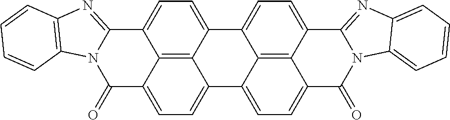
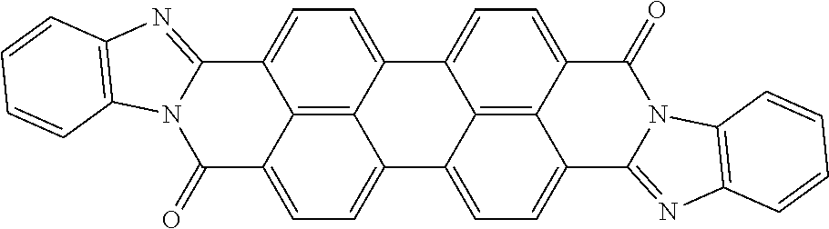
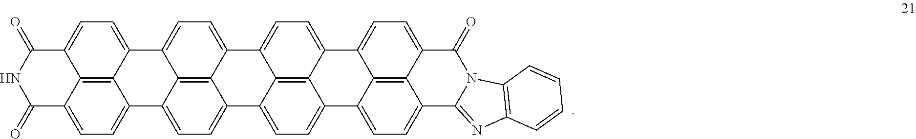
3. A coiled capacitor according to claim 1, wherein the rylene fragments is at least one selected from the group consisting of structures 1-21: ##STR00063## ##STR00064## ##STR00065##
4. A coiled capacitor according to claim 1, wherein the energy storage material comprises a ceramic slurry, a sputtered thin film, or a molecularly ordered crystal.
5. A coiled capacitor according to claim 1, wherein the plastic is selected from the list comprising polypropylene (PP), polyethylene terephthalate (PET), polyphenylene sulfide (PPS), polyethylene naphthalate (PEN), polycarbonate (PP), polystyrene (PS), and polytetrafluoroethylene (PTFE) and a thickness of the plastic layer cannot be less than 2 .mu.m.
Description
BACKGROUND
Capacitors with high volumetric energy density, high operating temperature, low equivalent series resistance (ESR), and long lifetime are critical components for pulse-power, automotive, and industrial electronics. The physical characteristics of the dielectric material in the capacitor are the primary determining factors for the performance of a capacitor. Accordingly, improvements in one or more of the physical properties of the dielectric material in a capacitor can result in corresponding performance improvements in the capacitor component, usually resulting in performance and lifetime enhancements of the electronics system or product in which it is embedded. Since improvements in capacitor dielectric can directly influence product size, product reliability, and product efficiency, there is a high value associated with such improvements.
Certain improvements in capacitor dielectric materials can be considered as enabling to a particular technology application. For example, capacitors with high permittivity, high dielectric strength, low ESR, and low dielectric dissipation factor will allow high frequency or pulse-power applications to be reduced to a practical size. High temperature operation will greatly simplify next-generation electric vehicles. Improved dielectrics will enable the specific power and reliability of switching power supplies, power conditioners, and filters to be increased. Improved energy density will decrease the area presently devoted to capacitor devices on printed circuit boards, reducing the weight and size of power conditioning systems, power supplies and down-hole tools for use in oil or gas wells.
To reduce the size of a capacitor while retaining all other physical and electrical characteristics, either an increase in the capacitor dielectric constant or dielectric breakdown strength is necessary. Both are fulfilled with the development of new thin, flexible dielectrics having high voltage breakdown strength, a high dielectric constant and a low ESR loss. Some applications additionally require a stable dielectric constant with no reduction in lifetime at temperatures exceeding 150[deg.] C.
High voltage non-polar capacitors are conventionally made using a metalized polymer film that is wound into a cylindrical shape. In conventional wound capacitors, the dielectric material is typically a polymer film. Common polymer dielectric materials include polycarbonate, polyethylene terephthalate (PET, also known as polyester), polypropylene, polystyrene, and polysulfone. Polymer dielectric-based foil capacitors are generally fabricated by placing alternating sheets of polymer and metal foil in a stack and rolling the stack into a tubular shape or depositing a metal film on one side of the polymer then rolling two stacked metalized polymer films into a tubular shape. Electrical wires are connected to each metal foil. The dielectric material exists in the form of self-supporting layers that are thick enough to sustain the necessary operating voltage (typically at least 3-6 micrometers). Unfortunately, the large thickness of the polymer sheets reduces the energy storage density. Usually the dielectric constant of these capacitors changes and the lifetime is shortened at temperatures in excess of 100-150.degree. C. due to deficiencies in the polymer material. Alternately, two polymer films coated with a thin layer of metal (usually 17-100 nanometers thick) are wound into a tubular shape to form a capacitor. The thin metal film has the advantage of clearing any short that may form if the polymer dielectric breaks down during operation. This may extend the life of the capacitor and minimize the chances of catastrophic failure of the capacitor. Conventional film capacitors do not have high energy density because the relative permittivity (also known as dielectric constant .kappa.) of the film is relatively low, e.g., less than about 5.
Amorphous SiO2, HfO2, other metal oxides and stacks of amorphous oxides and nitrides, e.g. SiO2/Si3N4, are disclosed in prior art as dielectric materials of capacitors. A flexible substrate comprised of an insulating polymer film coated with thin metal layers on both sides of the film and a process to deposit the amorphous oxides and oxide/nitride layers on the film to produce a material that can be rolled into cylindrical shapes is also disclosed in prior art.
In the prior art the metallized film capacitors are known. These capacitors include two tightly wound sheets, wrapped around a core. Each sheet includes a dielectric layer and a metallized layer. The metallized layer does not extend to the opposing ends of the sheet leaving a non-metallized margin on opposing sides of each sheet. The ends of the roll formed from the two tightly wound sheets are sprayed with a conductive metal to form a conducting termination for the capacitor. Capacitors made in this way can be used for a variety of purposes depending upon factors such as the type of sheet material as well as the thickness and dielectric constant of the sheet. Typical materials for the sheet are, for example, oriented polypropylene or poly-(ethylene)-terephtalate. The conductive metal termination is typically applied in a vacuum metallizer and is generally comprised of aluminum, zinc or alloys thereof.
SUMMARY
The present disclosure provides a coiled capacitor which may solve a problem of the further increase of volumetric and mass density of reserved energy associated with some energy storage devices, and at the same time reduce cost of materials.
Aspects of the present disclosure include use of materials engineered to obtain 1) high permittivity, 2) high dielectric strength (also known as breakdown field E.sub.BD) allowing high voltage, and 3) low amount of carrier substrate.
In an aspect, the present invention provides a coiled capacitor comprising a coil formed by a flexible multilayered tape, and a first terminating electrode (a first contact layer) and a second terminating electrode (a second contact layer) which are located on butts of the coil. The flexible multilayered tape contains the following sequence of layers: first metal layer, a layer of a plastic, second metal layer, a layer of energy storage material. The first metal layer forms an ohmic contact with the first terminating electrode (the first contact layer) and the second metal layer (the second contact layer) forms an ohmic contact with the second terminating electrode.
INCORPORATION BY REFERENCE
All publications, patents, and patent applications mentioned in this specification are herein incorporated by reference to the same extent as if each individual publication, patent, or patent application was specifically and individually indicated to be incorporated by reference.
BRIEF DESCRIPTION OF THE DRAWINGS
FIGS. 1a, 1b and 1c schematically show formation of sets of metal strips on top and bottom surfaces of the plastic layer.
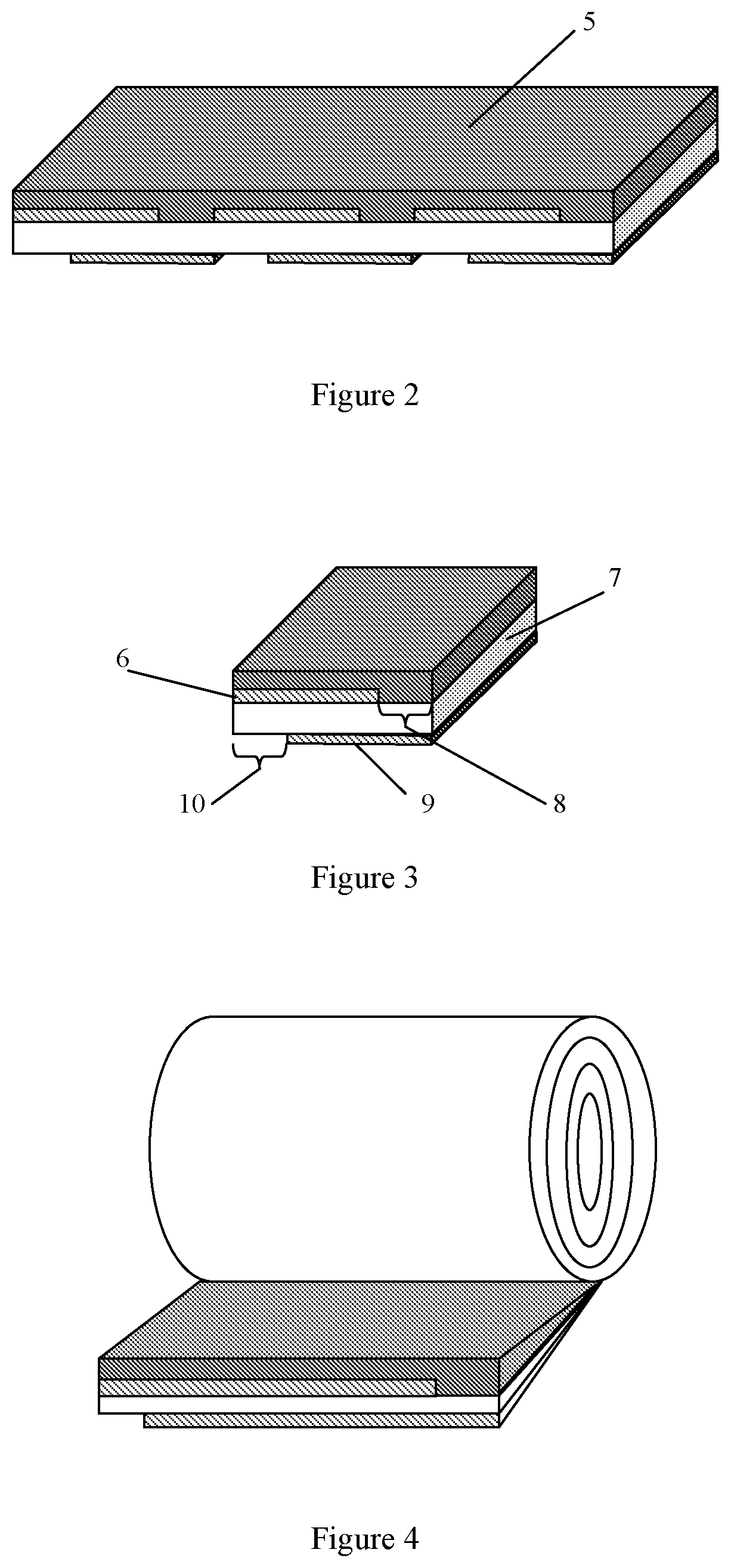
FIG. 2 shows a formation of the layer of the energy storage material on one of metalized surfaces of the plastic layer.
FIG. 3 shows a slitting of the intermediate product onto the multilayered tapes.
FIG. 4 shows a winding of the multilayered tape.
FIG. 5 shows a formation of the first terminating electrode and a second terminating electrode.
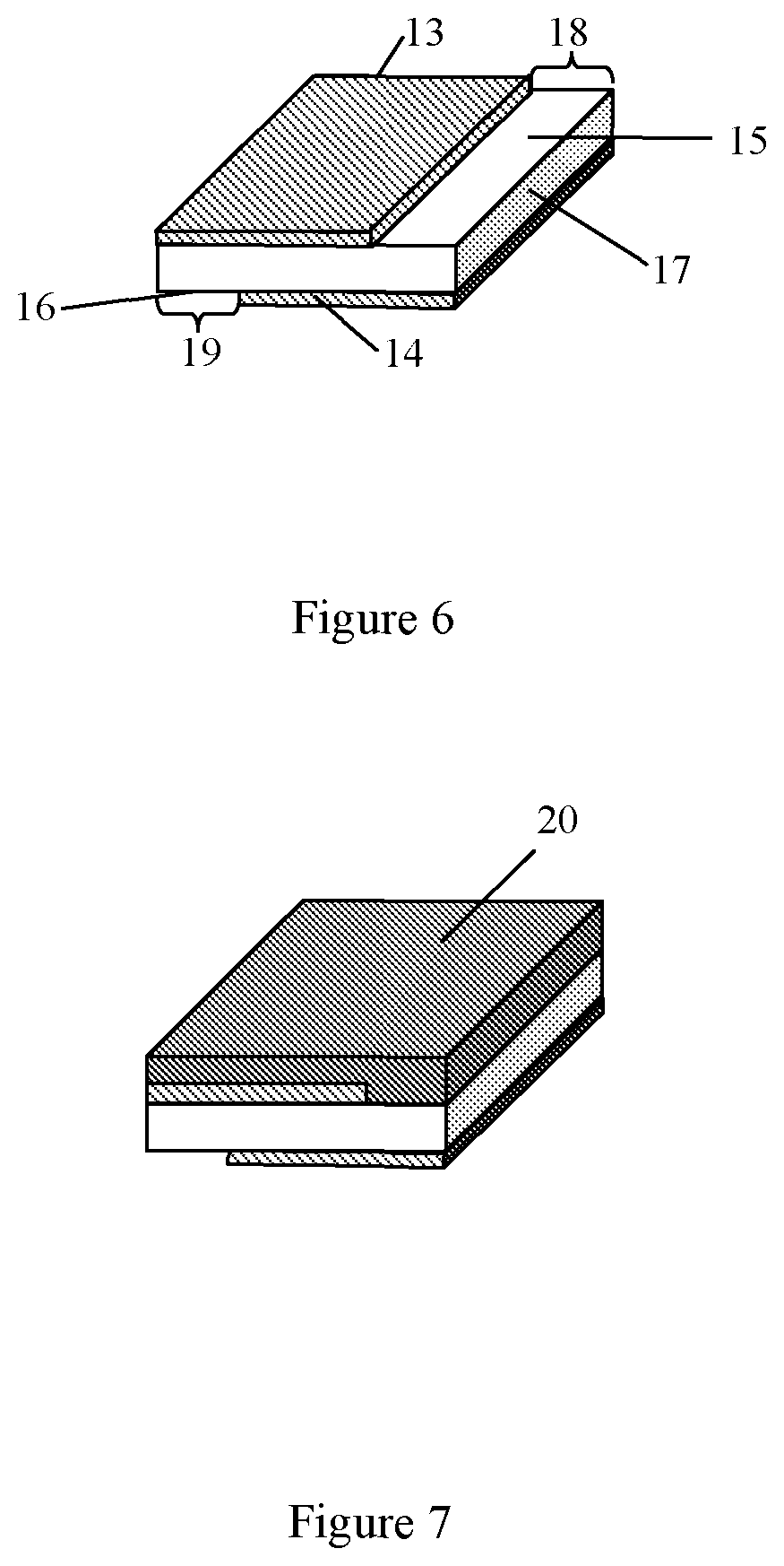
FIG. 6 shows a formation of two metal strips on top and bottom surfaces of the plastic layer according to the second embodiment.
FIG. 7 shows a formation of the layer of the energy storage material.
FIG. 8 shows a winding of the multilayered tape.
FIG. 9 shows a formation of the first terminating electrode and a second terminating electrode.
DETAILED DESCRIPTION
While various aspects of the present disclosure are shown and described herein, it will be obvious to those skilled in the art that such aspects are provided by way of example only. Numerous variations, changes, and substitutions may occur to those skilled in the art without departing from the invention. It should be understood that various alternatives to the aspects described herein may be employed.
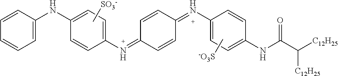
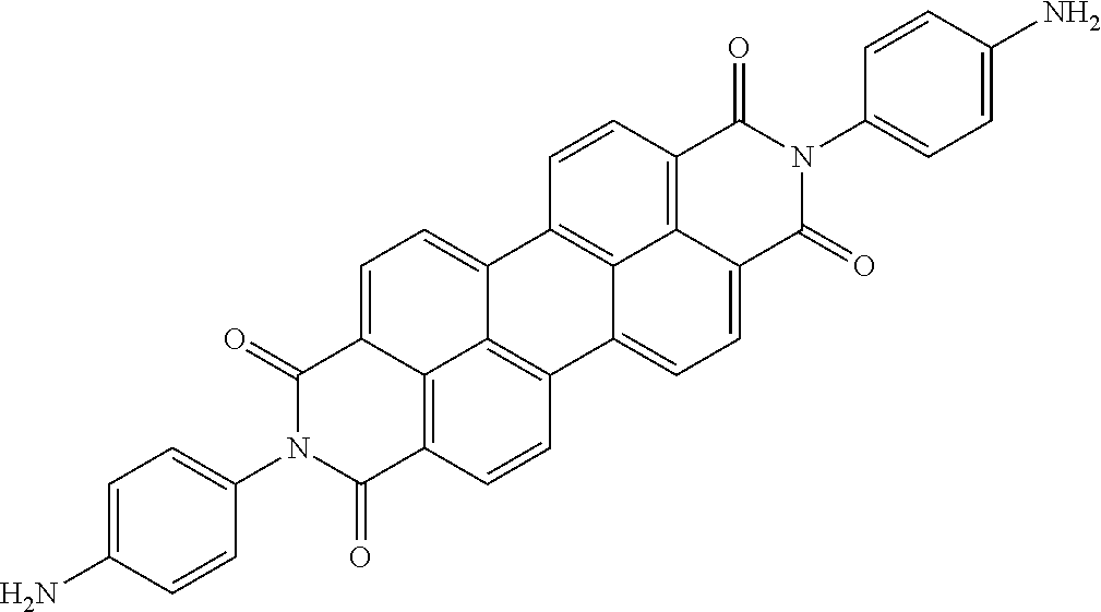
The present disclosure provides a coiled capacitor. According to one aspect of the present disclosure, the coiled capacitor further comprises a dielectric core around which the flexible multilayered tape is coiled. The energy storage material may be characterized by a dielectric constant .kappa. greater than about 100 and a breakdown field E.sub.bd about greater than or equal to about 0.001 volts (V)/nanometer (nm). The dielectric constant .kappa. may be greater than or equal to about 100, 200, 300, 400, 500, 1000, 2000, 3000, 4000, 5000, 6000, 7000, 8000, 9000, 10,000, or 100,000. The breakdown field may be greater than about 0.01 V/nm, 0.05 V/nm, 0.1 V/nm, 0.2 V/nm, 0.3 V/nm, 0.4 V/nm, 0.5 V/nm, 1 V/nm, or 10 V/nm. By way of example, and not by way of limitation, the energy storage material may be characterized by a dielectric constant .kappa. between about 100 and about 1,000,000 and a breakdown field E.sub.bd between about 0.01 V/nm and about 2.0 V/nm. By way of example, and not by way of limitation, the energy storage material may comprise rylene fragments. According to another aspect of the present disclosure, the rylene fragments may be selected from the list comprising structures 1-21 as given in Table 1.
TABLE-US-00001 TABLE 1 Examples of the energy storage material comprising the rylene fragments: ##STR00001## 1 ##STR00002## 2 ##STR00003## 3 ##STR00004## 4 ##STR00005## 5 ##STR00006## 6 ##STR00007## 7 ##STR00008## 8 ##STR00009## 9 ##STR00010## 10 ##STR00011## 11 ##STR00012## 12 ##STR00013## 13 ##STR00014## 14 ##STR00015## 15 ##STR00016## 16 ##STR00017## 17 ##STR00018## 18 ##STR00019## 19 ##STR00020## 20 ##STR00021## 21
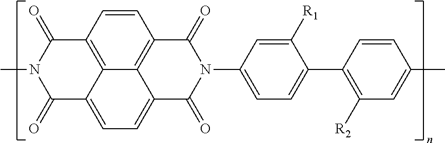
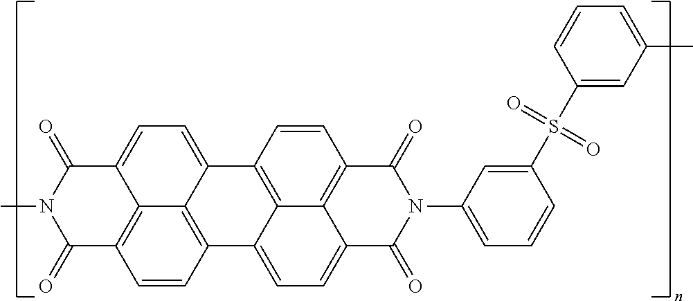
In one example of a coiled capacitor in accordance with aspects of the present disclosure, the energy storage material is selected from the list comprising doped oligoaniline and p-oligo-phenylene. In another example of a coiled capacitor, the doped oligoaniline is self-doped oligoaniline with SO.sub.3-- groups or COO-- groups on the phenyl rings of aniline. In still another embodiment of the coiled capacitor, the doped oligoaniline is mix-doped by organic structure-inorganic/organic acid mixed to oligoaniline in oxidized state, wherein the organic structure is selected from the list comprising alkyl, aryl and polymers thereof and the inorganic/organic acid is selected from the list comprising SO.sub.3H, COOH, HCl, H.sub.2SO.sub.4, H.sub.3PO.sub.4, HBF.sub.4, HPF.sub.6, benzoic acid and derivatives thereof. According to still another aspect of the present disclosure, the energy storage material may comprise a polymeric material soluble in organic solvents. In yet another embodiment of the present invention, the energy storage material comprises polymers soluble in organic solvents having a structure selected from the structures 22 to 27 as given in Table 2.
TABLE-US-00002 TABLE 2 Examples of the energy storage material comprising the polymers soluble in organic solvents ##STR00022## 22 ##STR00023## 23 ##STR00024## 24 ##STR00025## 25 ##STR00026## 26 ##STR00027## 27
wherein each R.sub.1 and R.sub.2 is independently selected from alkyl, aryl, substituted alkyl, and substituted aryl. In another embodiment of the coiled capacitor, the energy storage material comprises a colloidal composite with a dispersion of electro-conductive anisometric particles in an insulator matrix. In still another example of a coiled capacitor, the electro-conductive anisometric particles comprise an electro-conductive oligomer. In yet another example of the coiled capacitor, the material of the insulator matrix is selected from the group consisting of poly (acrylic acid) (PAA), poly(N-vinylpyrrolidone) (PVP), poly(vinylidene fluoride-hexafluoropropylene) [P(VDF-HFP)], ethylene propylene polymers, which include ethylene propylene rubber (EPR) and ethylene propylene diene monomer (EPDM), and silicone rubber (PDMSO) such as dimethyldicloro siloxane, dimethylsilane diol, and polydimethyl siloxane, polystyrene sulfonic acid (PSS). In one embodiment of the coiled capacitor, the energy storage material comprises a surfactant selected from: dodecylbenzene sulfonate (DBSA), polyoxyethylene glycol alkyl ethers, polyoxypropylene glycol alkyl ethers, polyoxyethylene glycol octylphenol ethers, polyoxyethylene glycol sorbitan alkyl esters, sorbitan alkyl esters, and dobecyldimethylamine oxide.
In another embodiment of the coiled capacitor, the energy storage material comprises ceramic slurries, sputtered thin films, and molecularly ordered crystals. As used herein the term molecularly ordered crystals refers to films assembled by cascade crystallization or films made from solutions comprising lyotropic liquid crystals. Examples of molecularly ordered crystals include, but are not limited to, energy storage molecular materials that are described, e.g., in U.S. patent application Ser. No. 14/719,072, filed May 21, 2015, the entire contents of which are incorporated herein by reference. By way of example, and not by way of limitation, a method for making molecularly ordered crystals from a colloidal system with supramolecular complexes may include the following steps: application of the colloidal system onto a substrate. The colloidal system typically possesses thixotropic properties, which are provided by maintaining a preset temperature and a certain concentration of the dispersed phase; external alignment upon the system, which can be produced using mechanical factors or by any other means, for example by applying an external electric field at normal or elevated temperature, with or without additional illumination, magnetic field, or optical field (e.g., coherent photovoltaic effect); the degree of the external alignment should be sufficient to impart necessary orientation to the kinetic units of the colloidal system and form a structure, which serves as a base of the crystal lattice of the crystal dielectric layer; and drying to remove solvents to form the final molecularly ordered crystal.
In still another example of the coiled capacitor, the plastic is selected from the list comprising polypropylene (PP), polyethylene terephthalate polyester (PET), polyphenylene sulfide (PPS), polyethylene naphthalate (PEN), polycarbonate (PP), polystyrene (PS), and polytetrafluoroethylene (PTFE). In yet another embodiment of the coiled capacitor, the thickness of the plastic layer cannot be less than 2 .mu.m. In still another embodiment of the coiled capacitor, the thickness of the plastic layer varies from 2.5 .mu.m to 52 .mu.m. In one example of the coiled capacitor, the plastic layer comprises polypropylene and the thickness of the plastic layer is equal to 12 .mu.m. In another example of the coiled capacitor, the material of the first metal layer and second metal layer independently selected from the list comprising Pt, Cu, Al, Ag, Au, Ni, and Al:Ni, and the metal foam. In still another example of the coiled capacitor, the thickness of the first and second contact layers independently varies from 10 nm to 1000 nm. In one embodiment of the coiled capacitor, the sheet resistance of the first and second contact layers independently cannot be less than 0.1 Ohm/Square. In another example of the coiled capacitor, the sheet resistance of the first and second contact layers independently varies from 0.1 Ohm/Square to 2.5 Ohm/Square. In yet another example of the coiled capacitor, the metal of the metal foam is selected from the list comprising Al, Ni, Fe, Cu. In one example of the coiled capacitor, the melting temperature of the metal foam is in the range 400 C-700 C. In another example of the coiled capacitor, the metal content in the metal foam for electrode is in the range of 5% up to 30% by weight. In still another example of the coiled capacitor, the metal foam is of closed "bubble" type with maximum conductance per metal content. In yet another example of the coiled capacitor, the size of "bubbles" is in the range of 100 nm up to 100 000 nm. In one example of the coiled capacitor, the material of the first terminating electrode and second terminating electrode independently selected from the list comprising Pt, Cu, Al, Ag, and Au. In another embodiment of the coiled capacitor, the first metal layer is deposited on a portion of a first surface of the plastic layer and this first surface has a first margin portion which is free of deposited metal, and wherein the second metal layer is deposited on a portion of a second surface of the plastic layer and this second surface has a second margin portion which is free of deposited metal and is located on an opposite edge of the plastic layer from the first margin portion.
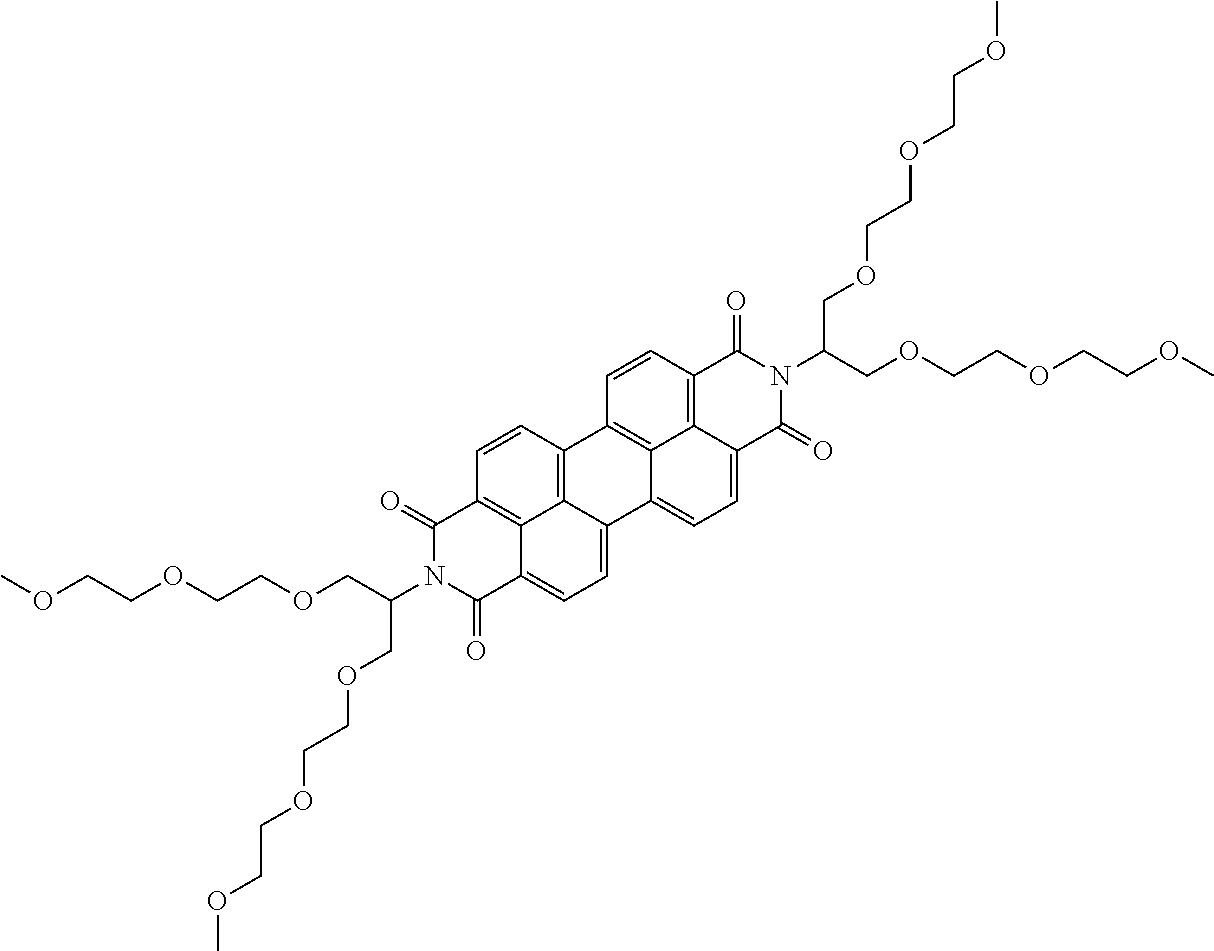
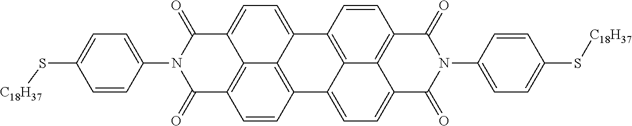
According to additional aspects of the present disclosure, the energy storage material may include supramolecules or stacks of molecules. Such supramolecules may be formed by self-assembling molecules that stack in rod like molecular structures. Examples of such structures include, but are not limited to, structures selected from the list comprising structures as given in Table 1 and also structures 28-62 as given in Table 3.
TABLE-US-00003 TABLE 3 additional examples of supramolecular structures in the energy storage material ##STR00028## 28 ##STR00029## 29 ##STR00030## 30 ##STR00031## 31 ##STR00032## 32 ##STR00033## 33 ##STR00034## 34 ##STR00035## 35 ##STR00036## 36 ##STR00037## 37 ##STR00038## 38 ##STR00039## 39 ##STR00040## 40 ##STR00041## 41 ##STR00042## 42 ##STR00043## 43 ##STR00044## 44 ##STR00045## 45 ##STR00046## 46 ##STR00047## 47 ##STR00048## 48 ##STR00049## 49 ##STR00050## 50 ##STR00051## 51 ##STR00052## 52 ##STR00053## 53 ##STR00054## 54 ##STR00055## 55 ##STR00056## 56 ##STR00057## 57 ##STR00058## 58 ##STR00059## 59 ##STR00060## 60 ##STR00061## 61 ##STR00062## 62
To form the energy storage material from such supramolecular structures, organic molecules may be modified using supramolecular chemistry and self-assembled in liquid to form lyotropic liquid crystals. The liquid containing the lyotropic liquid crystals is them coated onto a substrate and the liquid crystals align during coating. Liquid crystals then crystallize to form the energy storage material as the liquid dries.
In order that the invention may be more readily understood, reference is made to the following examples, which are intended to be illustrative of the invention, but are not intended to be limiting the scope.
EXAMPLES
Example 1
The example schematically describes a sequence of technological operations for manufacturing of a coiled capacitor in accordance with an aspect of the present disclosure. This example represents one of possible methods of manufacturing of the disclosed coiled capacitor. FIGS. 1a, 1b and 1c show formation of metal strips (1) on top (2, FIG. 1b) and bottom (3, FIG. 1c) surfaces of the plastic layer (4). FIG. 1a shows the metal strips located on the top surface are displaced relatively of the metal strips located on the bottom surface. In this Example the width of the metal strip may vary within the range from 1 cm to 100 cm. The width is not limited by the specified range of values. Generally, the desired width is computed for each application. Various factors can influence size of the width, such as roll size, power, energy, etc. The large influence on the width can render prospective application of the disclosed coiled capacitor. The thickness of the metal strip may vary within the range from 0.01 .mu.m to 1 .mu.m. The distance between strips may change from 0.5 mm to 3 mm. The key feature of this example is the use of one plastic layer as a load-carrying substrate for all layers in the capacitor that are coated onto this plastic layer or supported by this plastic layer.
Metal strips are formed onto opposite surfaces of the plastic layer so that margin portions which are free of deposited metal have been generated on each surface of the plastic layer and these margin portions are located on an opposite edge of the plastic layer. The following stage is formation of the layer of the energy storage material on one of metalized surfaces of the plastic layer shown in FIG. 2. This formation comprises two steps: first step is application of a solution of the energy storage material and second step comprises a drying the applied solution to form a solid layer of the energy storage material (5). The thickness of the layer of the energy storage material may vary within the range from 0.5 .mu.m to 50 .mu.m. Thus at this stage an intermediate product for the further formation of the coiled capacitor is formed. Then, a slitting of the intermediate product onto the multilayered tapes is made. The schematic view of the received multilayered tape is shown in the FIG. 3. FIG. 3 shows that the first metal layer (6) is deposited on a portion of a first surface of the plastic layer (7) and this first surface has a first margin portion (8) which is free of deposited metal, and wherein the second metal layer (9) is deposited on a portion of a second surface of the plastic layer (7) and this second surface has a second margin portion (10) which is free of deposited metal and is located on an opposite edge of the plastic layer from the first margin portion. Further a winding of the multilayered tape is carried out (see, FIG. 4). Then the first terminating electrode (a first contact layer) (11) and a second terminating electrode (a second contact layer) (12) located on butts of the coil are formed (see, FIG. 5). Finally, a healing is done by applying a precisely calibrated voltage across the first and second terminating electrodes of the coiled capacitor so that any existing defects will be "burned away".
Example 2
This example schematically describes another sequence of technological operations for manufacturing of the coiled capacitor. FIG. 6 shows formation of two metal strips (13) and (14) on top (15) and bottom (16) surfaces of a plastic layer (17). FIG. 6 shows the metal strip located on the top surface is displaced laterally relative to the metal strip located on the bottom surface. Thus, the first metal strip (13) is deposited on a portion of a first surface of the plastic layer (15) and this first surface has a first margin portion (18) which is free of deposited metal, and wherein the second metal strip (14) is deposited on a portion of a second surface of the plastic layer (16) and this second surface has a second margin portion (19) which is free of deposited metal and is located on an opposite edge of the plastic layer from the first margin portion. The thickness of the plastic layer varies from 2.5 .mu.m to 52 .mu.m. The width of a metal strip may vary within the range from 1 cm to 100 cm and its thickness may vary within the range from 0.01 .mu.m to 1 .mu.m. The plastic layer is used as a load-carrying substrate for all other layers in the capacitor that are coated onto this plastic layer or supported by this plastic layer.
The following stage is formation of the layer of the energy storage material (20) on one of metalized surfaces of the plastic layer shown in FIG. 7. This formation comprises two steps: first step is application of solution of the energy storage material and second step comprises a drying to form a solid layer of the energy storage material (20). Thickness of the layer of the energy storage material may vary within the range from 0.5 .mu.m to 50 .mu.m. Further a winding of the multilayered tape into a roll is carried out (see, FIG. 8). Then the first terminating electrode (a first contact layer) (21) and a second terminating electrode (a second contact layer) (22) located on butts of the coil are formed (see, FIG. 9). Finally, a healing is done by applying a precisely calibrated voltage across the first and second terminating electrodes of the coiled capacitor so that any existing defects will be "burned away".
While the above is a complete description of the preferred embodiment of the present invention, it is possible to use various alternatives, modifications and equivalents. Therefore, the scope of the present invention should be determined not with reference to the above description but should, instead, be determined with reference to the appended claims, along with their full scope of equivalents. Any feature described herein, whether preferred or not, may be combined with any other feature described herein, whether preferred or not. In the claims that follow, the indefinite article "A", or "An" refers to a quantity of one or more of the item following the article, except where expressly stated otherwise. As used herein, in a listing of elements in the alternative, the word "or" is used in the logical inclusive sense, e.g., "X or Y" covers X alone, Y alone, or both X and Y together, except where expressly stated otherwise. Two or more elements listed as alternatives may be combined together. The appended claims are not to be interpreted as including means-plus-function limitations, unless such a limitation is explicitly recited in a given claim using the phrase "means for."
* * * * *
References
C00001
C00002
C00003
C00004
C00005
C00006
C00007
C00008
C00009
C00010
C00011
C00012
C00013

C00014

C00015

C00016

C00017

C00018

C00019

C00020

C00021

C00022

C00023

C00024

C00025

C00026

C00027
C00028

C00029
C00030

C00031

C00032

C00033

C00034

C00035

C00036

C00037

C00038

C00039

C00040
C00041

C00042

C00043

C00044

C00045

C00046

C00047

C00048

C00049
C00050
C00051

C00052

C00053

C00054

C00055

C00056

C00057
C00058

C00059

C00060

C00061

C00062

C00063

C00064

C00065
D00000

D00001

D00002
D00003

D00004
D00005

D00006

P00001

XML
uspto.report is an independent third-party trademark research tool that is not affiliated, endorsed, or sponsored by the United States Patent and Trademark Office (USPTO) or any other governmental organization. The information provided by uspto.report is based on publicly available data at the time of writing and is intended for informational purposes only.
While we strive to provide accurate and up-to-date information, we do not guarantee the accuracy, completeness, reliability, or suitability of the information displayed on this site. The use of this site is at your own risk. Any reliance you place on such information is therefore strictly at your own risk.
All official trademark data, including owner information, should be verified by visiting the official USPTO website at www.uspto.gov. This site is not intended to replace professional legal advice and should not be used as a substitute for consulting with a legal professional who is knowledgeable about trademark law.