Calibration interface
Wilberding , et al. December 1, 2
U.S. patent number 10,853,022 [Application Number 16/530,324] was granted by the patent office on 2020-12-01 for calibration interface. This patent grant is currently assigned to Sonos, Inc.. The grantee listed for this patent is Sonos, Inc.. Invention is credited to Dayn Wilberding, Sein Woo.


View All Diagrams
| United States Patent | 10,853,022 |
| Wilberding , et al. | December 1, 2020 |
Calibration interface
Abstract
Example techniques relate to calibration interfaces that facilitate calibration of a playback device. An example implementation may involve displaying, on a graphical display, a sequence of control interfaces to guide calibration of a playback device during a calibration sequence comprising (i) a spatial calibration component and (ii) a spectral calibration component. Displaying the sequence of control interfaces includes displaying one or more spatial calibration interfaces comprising a guide to perform the spatial calibration component of the calibration sequence. The spatial calibration component involves calibration of the playback device for a particular location within an environment. Displaying the sequence of control interfaces also includes displaying one or more spectral calibration interfaces comprising a guide to perform the spectral calibration component of the calibration sequence. The spectral calibration component involves calibration of the playback device for the environment.
| Inventors: | Wilberding; Dayn (Santa Barbara, CA), Woo; Sein (Somerville, MA) | ||||||||||
|---|---|---|---|---|---|---|---|---|---|---|---|
| Applicant: |
|
||||||||||
| Assignee: | Sonos, Inc. (Santa Barbara,
CA) |
||||||||||
| Family ID: | 1000005215579 | ||||||||||
| Appl. No.: | 16/530,324 | ||||||||||
| Filed: | August 2, 2019 |
Prior Publication Data
| Document Identifier | Publication Date | |
|---|---|---|
| US 20190354337 A1 | Nov 21, 2019 | |
Related U.S. Patent Documents
| Application Number | Filing Date | Patent Number | Issue Date | ||
|---|---|---|---|---|---|
| 15217399 | Jul 22, 2016 | 10372406 | |||
| Current U.S. Class: | 1/1 |
| Current CPC Class: | G06F 3/162 (20130101); H04S 7/305 (20130101); H04S 7/301 (20130101); G06F 3/165 (20130101) |
| Current International Class: | G06F 3/16 (20060101); H04S 7/00 (20060101) |
References Cited [Referenced By]
U.S. Patent Documents
| 4306113 | December 1981 | Morton |
| 4342104 | July 1982 | Jack |
| 4504704 | March 1985 | Ohyaba et al. |
| 4592088 | May 1986 | Shimada |
| 4628530 | December 1986 | Op et al. |
| 4631749 | December 1986 | Rapaich |
| 4694484 | September 1987 | Atkinson et al. |
| 4773094 | September 1988 | Dolby |
| 4995778 | February 1991 | Bruessel |
| 5218710 | June 1993 | Yamaki et al. |
| 5255326 | October 1993 | Stevenson |
| 5323257 | June 1994 | Abe et al. |
| 5386478 | January 1995 | Plunkett |
| 5440644 | August 1995 | Farinelli et al. |
| 5553147 | September 1996 | Pineau |
| 5581621 | December 1996 | Koyama et al. |
| 5757927 | May 1998 | Gerzon et al. |
| 5761320 | June 1998 | Farinelli et al. |
| 5910991 | June 1999 | Farrar |
| 5923902 | July 1999 | Inagaki |
| 5939656 | August 1999 | Suda |
| 6018376 | January 2000 | Nakatani |
| 6032202 | February 2000 | Lea et al. |
| 6072879 | June 2000 | Ouchi et al. |
| 6111957 | August 2000 | Thomasson |
| 6256554 | July 2001 | DiLorenzo |
| 6363155 | March 2002 | Horbach |
| 6404811 | June 2002 | Cvetko et al. |
| 6469633 | October 2002 | Wachter et al. |
| 6522886 | February 2003 | Youngs et al. |
| 6573067 | June 2003 | Dib-Hajj et al. |
| 6611537 | August 2003 | Edens et al. |
| 6631410 | October 2003 | Kowalski et al. |
| 6639989 | October 2003 | Zacharov et al. |
| 6643744 | November 2003 | Cheng |
| 6704421 | March 2004 | Kitamura |
| 6721428 | April 2004 | Allred et al. |
| 6757517 | June 2004 | Chang et al. |
| 6760451 | July 2004 | Craven et al. |
| 6766025 | July 2004 | Levy et al. |
| 6778869 | August 2004 | Champion |
| 6798889 | September 2004 | Dicker |
| 6862440 | March 2005 | Sampath |
| 6916980 | July 2005 | Ishida et al. |
| 6931134 | August 2005 | Waller, Jr. et al. |
| 6985694 | January 2006 | De Bonet et al. |
| 6990211 | January 2006 | Parker |
| 7031476 | April 2006 | Chrisop et al. |
| 7039212 | May 2006 | Poling et al. |
| 7058186 | June 2006 | Tanaka |
| 7072477 | July 2006 | Kincaid |
| 7103187 | September 2006 | Neuman |
| 7130608 | October 2006 | Hollstrom et al. |
| 7130616 | October 2006 | Janik |
| 7143939 | December 2006 | Henzerling |
| 7187947 | March 2007 | White et al. |
| 7236773 | June 2007 | Thomas |
| 7289637 | October 2007 | Montag et al. |
| 7295548 | November 2007 | Blank et al. |
| 7312785 | December 2007 | Tsuk et al. |
| 7391791 | June 2008 | Balassanian et al. |
| 7477751 | January 2009 | Lyon et al. |
| 7483538 | January 2009 | McCarty et al. |
| 7483540 | January 2009 | Rabinowitz et al. |
| 7489784 | February 2009 | Yoshino |
| 7490044 | February 2009 | Kulkarni |
| 7492909 | February 2009 | Carter et al. |
| 7519188 | April 2009 | Berardi et al. |
| 7529377 | May 2009 | Nackvi et al. |
| 7571014 | August 2009 | Lambourne et al. |
| 7590772 | September 2009 | Marriott et al. |
| 7630500 | December 2009 | Beckman et al. |
| 7630501 | December 2009 | Blank et al. |
| 7643894 | January 2010 | Braithwaite et al. |
| 7657910 | February 2010 | McAulay et al. |
| 7664276 | February 2010 | McKee |
| 7676044 | March 2010 | Sasaki et al. |
| 7689305 | March 2010 | Kreifeldt et al. |
| 7720237 | May 2010 | Bharitkar et al. |
| 7742740 | June 2010 | Goldberg et al. |
| 7769183 | August 2010 | Bharitkar et al. |
| 7796068 | September 2010 | Raz et al. |
| 7835689 | November 2010 | Goldberg et al. |
| 7853341 | December 2010 | McCarty et al. |
| 7876903 | January 2011 | Sauk |
| 7925203 | April 2011 | Lane et al. |
| 7949140 | May 2011 | Kino |
| 7949707 | May 2011 | McDowall et al. |
| 7961893 | June 2011 | Kino |
| 7970922 | June 2011 | Svendsen |
| 7987294 | July 2011 | Bryce et al. |
| 8005228 | August 2011 | Bharitkar et al. |
| 8014423 | September 2011 | Thaler et al. |
| 8045721 | October 2011 | Burgan et al. |
| 8045952 | October 2011 | Qureshey et al. |
| 8050652 | November 2011 | Qureshey et al. |
| 8063698 | November 2011 | Howard |
| 8074253 | December 2011 | Nathan |
| 8103009 | January 2012 | McCarty et al. |
| 8116476 | February 2012 | Inohara |
| 8126172 | February 2012 | Horbach et al. |
| 8131390 | March 2012 | Braithwaite et al. |
| 8139774 | March 2012 | Berardi et al. |
| 8144883 | March 2012 | Pdersen et al. |
| 8160276 | April 2012 | Liao et al. |
| 8160281 | April 2012 | Kim et al. |
| 8170260 | May 2012 | Reining et al. |
| 8175292 | May 2012 | Aylward et al. |
| 8175297 | May 2012 | Ho et al. |
| 8194874 | June 2012 | Starobin et al. |
| 8229125 | July 2012 | Short |
| 8233632 | July 2012 | MacDonald et al. |
| 8234395 | July 2012 | Millington et al. |
| 8238547 | August 2012 | Ohki et al. |
| 8238578 | August 2012 | Aylward |
| 8243961 | August 2012 | Morrill |
| 8264408 | September 2012 | Kainulainen |
| 8265310 | September 2012 | Berardi et al. |
| 8270620 | September 2012 | Christensen et al. |
| 8279709 | October 2012 | Choisel et al. |
| 8281001 | October 2012 | Busam et al. |
| 8290185 | October 2012 | Kim |
| 8291349 | October 2012 | Park et al. |
| 8300845 | October 2012 | Zurek et al. |
| 8306235 | November 2012 | Mahowald |
| 8325931 | December 2012 | Howard et al. |
| 8325935 | December 2012 | Rutschman |
| 8325944 | December 2012 | Duwenhorst et al. |
| 8331585 | December 2012 | Hagen et al. |
| 8332414 | December 2012 | Nguyen et al. |
| 8379876 | February 2013 | Zhang |
| 8391501 | March 2013 | Khawand et al. |
| 8392505 | March 2013 | Haughay et al. |
| 8401202 | March 2013 | Brooking |
| 8433076 | April 2013 | Zurek et al. |
| 8452020 | May 2013 | Gregg et al. |
| 8463184 | June 2013 | Dua |
| 8483853 | July 2013 | Lambourne |
| 8488799 | July 2013 | Goldstein et al. |
| 8503669 | August 2013 | Mao |
| 8527876 | September 2013 | Wood et al. |
| 8577045 | November 2013 | Gibbs |
| 8577048 | November 2013 | Chaikin et al. |
| 8600075 | December 2013 | Lim |
| 8620006 | December 2013 | Berardi et al. |
| 8682002 | March 2014 | Wihardja et al. |
| 8731206 | May 2014 | Park |
| 8755538 | June 2014 | Kwon |
| 8798280 | August 2014 | Goldberg et al. |
| 8819554 | August 2014 | Basso et al. |
| 8831244 | September 2014 | Apfel |
| 8855319 | October 2014 | Liu et al. |
| 8862273 | October 2014 | Karr |
| 8879761 | November 2014 | Johnson et al. |
| 8903526 | December 2014 | Beckhardt et al. |
| 8914559 | December 2014 | Kalayjian et al. |
| 8930005 | January 2015 | Reimann et al. |
| 8934647 | January 2015 | Joyce et al. |
| 8934655 | January 2015 | Breen et al. |
| 8942252 | January 2015 | Balassanian et al. |
| 8965033 | February 2015 | Wiggins |
| 8965546 | February 2015 | Visser et al. |
| 8977974 | March 2015 | Kraut |
| 8984442 | March 2015 | Pirnack et al. |
| 8989406 | March 2015 | Wong et al. |
| 8995687 | March 2015 | Marino, Jr. et al. |
| 8996370 | March 2015 | Ansell |
| 9020153 | April 2015 | Britt, Jr. |
| 9021153 | April 2015 | Lu |
| 9065929 | June 2015 | Chen et al. |
| 9084058 | July 2015 | Reilly et al. |
| 9100766 | August 2015 | Soulodre et al. |
| 9106192 | August 2015 | Sheen et al. |
| 9179233 | November 2015 | Kang |
| 9215545 | December 2015 | Dublin et al. |
| 9219460 | December 2015 | Bush |
| 9231545 | January 2016 | Agustin et al. |
| 9286384 | March 2016 | Kuper et al. |
| 9288597 | March 2016 | Carlsson et al. |
| 9300266 | March 2016 | Grokop |
| 9319816 | April 2016 | Narayanan |
| 9451377 | September 2016 | Massey et al. |
| 9462399 | October 2016 | Bharitkar et al. |
| 9467779 | October 2016 | Iyengar et al. |
| 9472201 | October 2016 | Sleator |
| 9489948 | November 2016 | Chu et al. |
| 9524098 | December 2016 | Griffiths et al. |
| 9538305 | January 2017 | Lehnert et al. |
| 9538308 | January 2017 | Isaac et al. |
| 9560449 | January 2017 | Carlsson et al. |
| 9560460 | January 2017 | Chaikin et al. |
| 9609383 | March 2017 | Hirst |
| 9615171 | April 2017 | O'Neill et al. |
| 9648422 | May 2017 | Sheen et al. |
| 9674625 | June 2017 | Armstrong-Muntner et al. |
| 9678708 | June 2017 | Bierbower et al. |
| 9689960 | June 2017 | Barton et al. |
| 9690271 | June 2017 | Sheen et al. |
| 9690539 | June 2017 | Sheen et al. |
| 9706323 | July 2017 | Sheen et al. |
| 9715365 | July 2017 | Kusano et al. |
| 9723420 | August 2017 | Family et al. |
| 9736584 | August 2017 | Sheen et al. |
| 9743207 | August 2017 | Hartung |
| 9743208 | August 2017 | Oishi et al. |
| 9749763 | August 2017 | Sheen |
| 9763018 | September 2017 | McPherson et al. |
| 9781532 | October 2017 | Sheen |
| 9788113 | October 2017 | Wilberding et al. |
| 9860662 | January 2018 | Jarvis et al. |
| 9864574 | January 2018 | Hartung et al. |
| 9910634 | March 2018 | Sheen et al. |
| 9916126 | March 2018 | Lang |
| 9952825 | April 2018 | Sheen |
| 9984703 | May 2018 | Ur et al. |
| 10045142 | August 2018 | McPherson et al. |
| 10154359 | December 2018 | Sheen |
| 10206052 | February 2019 | Perianu |
| 2001/0038702 | November 2001 | Lavoie et al. |
| 2001/0042107 | November 2001 | Palm |
| 2001/0043592 | November 2001 | Jimenez et al. |
| 2001/0053228 | December 2001 | Jones |
| 2002/0022453 | February 2002 | Balog et al. |
| 2002/0026442 | February 2002 | Lipscomb et al. |
| 2002/0078161 | June 2002 | Cheng |
| 2002/0089529 | July 2002 | Robbin |
| 2002/0124097 | September 2002 | Isely et al. |
| 2002/0126852 | September 2002 | Kashani et al. |
| 2002/0136414 | September 2002 | Jordan et al. |
| 2002/0146136 | October 2002 | Carter et al. |
| 2003/0002689 | January 2003 | Folio |
| 2003/0031334 | February 2003 | Layton et al. |
| 2003/0157951 | August 2003 | Hasty |
| 2003/0161479 | August 2003 | Yang et al. |
| 2003/0161492 | August 2003 | Miller et al. |
| 2003/0179891 | September 2003 | Rabinowitz et al. |
| 2003/0235311 | December 2003 | Grancea et al. |
| 2004/0024478 | February 2004 | Hans et al. |
| 2004/0131338 | July 2004 | Asada et al. |
| 2004/0237750 | December 2004 | Smith et al. |
| 2005/0031143 | February 2005 | Devantier et al. |
| 2005/0063554 | March 2005 | Devantier et al. |
| 2005/0147261 | July 2005 | Yeh |
| 2005/0157885 | July 2005 | Olney et al. |
| 2006/0008256 | January 2006 | Khedouri et al. |
| 2006/0026521 | February 2006 | Hotelling et al. |
| 2006/0032357 | February 2006 | Roovers et al. |
| 2006/0195480 | August 2006 | Spiegelman et al. |
| 2006/0225097 | October 2006 | Lawrence-Apfelbaum |
| 2007/0003067 | January 2007 | Gierl et al. |
| 2007/0025559 | February 2007 | Mihelich et al. |
| 2007/0032895 | February 2007 | Nackvi et al. |
| 2007/0038999 | February 2007 | Millington |
| 2007/0086597 | April 2007 | Kino |
| 2007/0116254 | May 2007 | Looney et al. |
| 2007/0121955 | May 2007 | Johnston et al. |
| 2007/0142944 | June 2007 | Goldberg et al. |
| 2008/0002839 | January 2008 | Eng |
| 2008/0014989 | January 2008 | Sandegard et al. |
| 2008/0065247 | March 2008 | Igoe |
| 2008/0069378 | March 2008 | Rabinowitz et al. |
| 2008/0077261 | March 2008 | Baudino et al. |
| 2008/0098027 | April 2008 | Aarts |
| 2008/0136623 | June 2008 | Calvarese |
| 2008/0144864 | June 2008 | Huon et al. |
| 2008/0175411 | July 2008 | Greve |
| 2008/0214160 | September 2008 | Jonsson |
| 2008/0232603 | September 2008 | Soulodre et al. |
| 2008/0266385 | October 2008 | Smith et al. |
| 2008/0281523 | November 2008 | Dahl et al. |
| 2009/0003613 | January 2009 | Christensen et al. |
| 2009/0024662 | January 2009 | Park et al. |
| 2009/0047993 | February 2009 | Vasa |
| 2009/0063274 | March 2009 | Dublin, III et al. |
| 2009/0110218 | April 2009 | Swain |
| 2009/0138507 | May 2009 | Burckart et al. |
| 2009/0147134 | June 2009 | Iwamatsu |
| 2009/0175476 | July 2009 | Bottum |
| 2009/0180632 | July 2009 | Goldberg et al. |
| 2009/0196428 | August 2009 | Kim |
| 2009/0202082 | August 2009 | Bharitkar et al. |
| 2009/0252481 | October 2009 | Ekstrand |
| 2009/0304194 | December 2009 | Eggleston et al. |
| 2009/0304205 | December 2009 | Hardacker et al. |
| 2009/0316923 | December 2009 | Tashev et al. |
| 2010/0013550 | January 2010 | Tanaka |
| 2010/0095332 | April 2010 | Gran et al. |
| 2010/0128902 | May 2010 | Liu et al. |
| 2010/0135501 | June 2010 | Corbett et al. |
| 2010/0142735 | June 2010 | Yoon et al. |
| 2010/0146445 | June 2010 | Kraut |
| 2010/0162117 | June 2010 | Basso et al. |
| 2010/0189203 | July 2010 | Wilhelmsson et al. |
| 2010/0195846 | August 2010 | Yokoyama |
| 2010/0272270 | October 2010 | Chaikin et al. |
| 2010/0296659 | November 2010 | Tanaka |
| 2010/0303248 | December 2010 | Tawada |
| 2010/0303250 | December 2010 | Goldberg et al. |
| 2010/0323793 | December 2010 | Andall |
| 2011/0007904 | January 2011 | Tomoda et al. |
| 2011/0007905 | January 2011 | Sato et al. |
| 2011/0087842 | April 2011 | Lu et al. |
| 2011/0091055 | April 2011 | Leblanc |
| 2011/0135103 | June 2011 | Sun et al. |
| 2011/0150228 | June 2011 | Yoon et al. |
| 2011/0170710 | July 2011 | Son |
| 2011/0234480 | September 2011 | Fino et al. |
| 2011/0235808 | September 2011 | Kon |
| 2011/0268281 | November 2011 | Florencio et al. |
| 2012/0032928 | February 2012 | Alberth et al. |
| 2012/0051558 | March 2012 | Kim et al. |
| 2012/0057724 | March 2012 | Rabinowitz et al. |
| 2012/0063615 | March 2012 | Crockett et al. |
| 2012/0093320 | April 2012 | Flaks et al. |
| 2012/0127831 | May 2012 | Gicklhorn et al. |
| 2012/0140936 | June 2012 | Bonnick et al. |
| 2012/0148075 | June 2012 | Goh et al. |
| 2012/0183156 | July 2012 | Schlessinger et al. |
| 2012/0213391 | August 2012 | Usami et al. |
| 2012/0215530 | August 2012 | Harsch et al. |
| 2012/0237037 | September 2012 | Ninan et al. |
| 2012/0243697 | September 2012 | Frye et al. |
| 2012/0263325 | October 2012 | Freeman et al. |
| 2012/0268145 | October 2012 | Chandra et al. |
| 2012/0269356 | October 2012 | Sheerin et al. |
| 2012/0275613 | November 2012 | Soulodre et al. |
| 2012/0283593 | November 2012 | Searchfield et al. |
| 2012/0288124 | November 2012 | Fejzo et al. |
| 2013/0010970 | January 2013 | Hegarty et al. |
| 2013/0028443 | January 2013 | Pance et al. |
| 2013/0051572 | February 2013 | Goh et al. |
| 2013/0066453 | March 2013 | Seefeldt |
| 2013/0108055 | May 2013 | Hanna et al. |
| 2013/0129102 | May 2013 | Li et al. |
| 2013/0129122 | May 2013 | Johnson et al. |
| 2013/0166227 | June 2013 | Hermann et al. |
| 2013/0202131 | August 2013 | Kemmochi et al. |
| 2013/0211843 | August 2013 | Clarkson |
| 2013/0216071 | August 2013 | Maher et al. |
| 2013/0223642 | August 2013 | Warren et al. |
| 2013/0230175 | September 2013 | Bech et al. |
| 2013/0259254 | October 2013 | Xiang et al. |
| 2013/0279706 | October 2013 | Marti et al. |
| 2013/0305152 | November 2013 | Griffiths et al. |
| 2013/0315405 | November 2013 | Kanishima |
| 2013/0329896 | December 2013 | Krishnaswamy et al. |
| 2013/0331970 | December 2013 | Beckhardt et al. |
| 2014/0003622 | January 2014 | Ikizyan et al. |
| 2014/0003623 | January 2014 | Lang |
| 2014/0003625 | January 2014 | Sheen et al. |
| 2014/0003626 | January 2014 | Holman et al. |
| 2014/0003635 | January 2014 | Mohammad et al. |
| 2014/0016784 | January 2014 | Sen et al. |
| 2014/0016786 | January 2014 | Sen |
| 2014/0016802 | January 2014 | Sen |
| 2014/0023196 | January 2014 | Xiang et al. |
| 2014/0029201 | January 2014 | Yang et al. |
| 2014/0032709 | January 2014 | Saussy et al. |
| 2014/0037097 | February 2014 | Labosco |
| 2014/0037107 | February 2014 | Marino, Jr. et al. |
| 2014/0052770 | February 2014 | Gran et al. |
| 2014/0064501 | March 2014 | Olsen et al. |
| 2014/0079242 | March 2014 | Nguyen et al. |
| 2014/0084014 | March 2014 | Sim et al. |
| 2014/0086423 | March 2014 | Domingo et al. |
| 2014/0112481 | April 2014 | Li et al. |
| 2014/0119551 | May 2014 | Bharitkar et al. |
| 2014/0126730 | May 2014 | Crawley et al. |
| 2014/0161265 | June 2014 | Chaikin et al. |
| 2014/0169569 | June 2014 | Toivanen et al. |
| 2014/0180684 | June 2014 | Strub |
| 2014/0192986 | July 2014 | Lee et al. |
| 2014/0219456 | August 2014 | Morrell et al. |
| 2014/0219483 | August 2014 | Hong |
| 2014/0226823 | August 2014 | Sen et al. |
| 2014/0242913 | August 2014 | Pang |
| 2014/0267148 | September 2014 | Luna et al. |
| 2014/0270202 | September 2014 | Ivanov et al. |
| 2014/0270282 | September 2014 | Tammi |
| 2014/0273859 | September 2014 | Luna et al. |
| 2014/0279889 | September 2014 | Luna et al. |
| 2014/0285313 | September 2014 | Luna et al. |
| 2014/0286496 | September 2014 | Luna et al. |
| 2014/0294200 | October 2014 | Baumgarte et al. |
| 2014/0294201 | October 2014 | Johnson |
| 2014/0310269 | October 2014 | Zhang et al. |
| 2014/0321670 | October 2014 | Nystrom et al. |
| 2014/0323036 | October 2014 | Daley et al. |
| 2014/0334644 | November 2014 | Selig et al. |
| 2014/0341399 | November 2014 | Dusse |
| 2014/0344689 | November 2014 | Scott et al. |
| 2014/0355768 | December 2014 | Sen et al. |
| 2014/0355794 | December 2014 | Morrell et al. |
| 2015/0011195 | January 2015 | Li |
| 2015/0016642 | January 2015 | Walsh et al. |
| 2015/0023509 | January 2015 | Devantier et al. |
| 2015/0031287 | January 2015 | Pang et al. |
| 2015/0032844 | January 2015 | Tarr et al. |
| 2015/0036847 | February 2015 | Donaldson |
| 2015/0036848 | February 2015 | Donaldson |
| 2015/0043736 | February 2015 | Olsen et al. |
| 2015/0063610 | March 2015 | Mossner |
| 2015/0078586 | March 2015 | Ang et al. |
| 2015/0078596 | March 2015 | Sprogis et al. |
| 2015/0100991 | April 2015 | Risberg et al. |
| 2015/0146886 | May 2015 | Baumgarte |
| 2015/0149943 | May 2015 | Nguyen et al. |
| 2015/0161360 | June 2015 | Paruchuri et al. |
| 2015/0195666 | July 2015 | Massey et al. |
| 2015/0201274 | July 2015 | Ellner et al. |
| 2015/0208184 | July 2015 | Tan et al. |
| 2015/0220558 | August 2015 | Snibbe et al. |
| 2015/0223002 | August 2015 | Mehta et al. |
| 2015/0229699 | August 2015 | Liu |
| 2015/0260754 | September 2015 | Perotti et al. |
| 2015/0271616 | September 2015 | Kechichian et al. |
| 2015/0281866 | October 2015 | Williams et al. |
| 2015/0289064 | October 2015 | Jensen et al. |
| 2015/0358756 | December 2015 | Harma et al. |
| 2015/0382128 | December 2015 | Ridihalgh et al. |
| 2016/0007116 | January 2016 | Holman |
| 2016/0011850 | January 2016 | Sheen et al. |
| 2016/0014509 | January 2016 | Hansson et al. |
| 2016/0014536 | January 2016 | Sheen |
| 2016/0021458 | January 2016 | Johnson et al. |
| 2016/0021473 | January 2016 | Riggi |
| 2016/0021481 | January 2016 | Johnson et al. |
| 2016/0027467 | January 2016 | Proud |
| 2016/0029142 | January 2016 | Isaac et al. |
| 2016/0035337 | February 2016 | Aggarwal et al. |
| 2016/0036881 | February 2016 | Tembey et al. |
| 2016/0037277 | February 2016 | Matsumoto et al. |
| 2016/0061597 | March 2016 | De et al. |
| 2016/0073210 | March 2016 | Sheen |
| 2016/0088438 | March 2016 | O'Keeffe |
| 2016/0119730 | April 2016 | Virtanen |
| 2016/0140969 | May 2016 | Srinivasan et al. |
| 2016/0165297 | June 2016 | Jamal-Syed et al. |
| 2016/0192098 | June 2016 | Oishi et al. |
| 2016/0192099 | June 2016 | Oishi et al. |
| 2016/0212535 | July 2016 | Le et al. |
| 2016/0239255 | August 2016 | Chavez et al. |
| 2016/0260140 | September 2016 | Shirley et al. |
| 2016/0309276 | October 2016 | Ridihalgh et al. |
| 2016/0330562 | November 2016 | Crockett |
| 2016/0366517 | December 2016 | Chandran et al. |
| 2017/0069338 | March 2017 | Elliot et al. |
| 2017/0083279 | March 2017 | Sheen et al. |
| 2017/0086003 | March 2017 | Rabinowitz et al. |
| 2017/0105084 | April 2017 | Holman |
| 2017/0142532 | May 2017 | Pan |
| 2017/0207762 | July 2017 | Porter et al. |
| 2017/0223447 | August 2017 | Johnson et al. |
| 2017/0230772 | August 2017 | Johnson et al. |
| 2017/0257722 | September 2017 | Kerdranvat et al. |
| 2017/0280265 | September 2017 | Po |
| 2017/0303039 | October 2017 | Iyer et al. |
| 2017/0311108 | October 2017 | Patel et al. |
| 2017/0374482 | December 2017 | McPherson et al. |
| 2019/0037328 | January 2019 | McPherson et al. |
| 1447624 | Oct 2003 | CN | |||
| 101366177 | Feb 2009 | CN | |||
| 101491116 | Jul 2009 | CN | |||
| 102318325 | Jan 2012 | CN | |||
| 102893633 | Jan 2013 | CN | |||
| 103988523 | Aug 2014 | CN | |||
| 105163221 | Dec 2015 | CN | |||
| 0505949 | Sep 1992 | EP | |||
| 0772374 | May 1997 | EP | |||
| 1133896 | Aug 2002 | EP | |||
| 1349427 | Oct 2003 | EP | |||
| 1389853 | Feb 2004 | EP | |||
| 2043381 | Apr 2009 | EP | |||
| 1349427 | Dec 2009 | EP | |||
| 2161950 | Mar 2010 | EP | |||
| 2194471 | Jun 2010 | EP | |||
| 2197220 | Jun 2010 | EP | |||
| 2429155 | Mar 2012 | EP | |||
| 1825713 | Oct 2012 | EP | |||
| 2613573 | Jul 2013 | EP | |||
| 2591617 | Jun 2014 | EP | |||
| 2835989 | Feb 2015 | EP | |||
| 2860992 | Apr 2015 | EP | |||
| 3128767 | Feb 2017 | EP | |||
| 2974382 | Apr 2017 | EP | |||
| H02280199 | Nov 1990 | JP | |||
| H05199593 | Aug 1993 | JP | |||
| H05211700 | Aug 1993 | JP | |||
| H06327089 | Nov 1994 | JP | |||
| H0723490 | Jan 1995 | JP | |||
| H1069280 | Mar 1998 | JP | |||
| 2002502193 | Jan 2002 | JP | |||
| 2003143252 | May 2003 | JP | |||
| 2003304590 | Oct 2003 | JP | |||
| 2005086686 | Mar 2005 | JP | |||
| 2005538633 | Dec 2005 | JP | |||
| 2006017893 | Jan 2006 | JP | |||
| 2006180039 | Jul 2006 | JP | |||
| 2007068125 | Mar 2007 | JP | |||
| 2007271802 | Oct 2007 | JP | |||
| 2008228133 | Sep 2008 | JP | |||
| 2009188474 | Aug 2009 | JP | |||
| 2010081124 | Apr 2010 | JP | |||
| 2011123376 | Jun 2011 | JP | |||
| 2011164166 | Aug 2011 | JP | |||
| 2011217068 | Oct 2011 | JP | |||
| 2013253884 | Dec 2013 | JP | |||
| 1020060116383 | Nov 2006 | KR | |||
| 1020080011831 | Feb 2008 | KR | |||
| 200153994 | Jul 2001 | WO | |||
| 0182650 | Nov 2001 | WO | |||
| 200182650 | Nov 2001 | WO | |||
| 2003093950 | Nov 2003 | WO | |||
| 2004066673 | Aug 2004 | WO | |||
| 2007016465 | Feb 2007 | WO | |||
| 2011139502 | Nov 2011 | WO | |||
| 2013016500 | Jan 2013 | WO | |||
| 2014032709 | Mar 2014 | WO | |||
| 2014032709 | Mar 2014 | WO | |||
| 2014036121 | Mar 2014 | WO | |||
| 2015024881 | Feb 2015 | WO | |||
| 2015108794 | Jul 2015 | WO | |||
| 2015178950 | Nov 2015 | WO | |||
| 2016040324 | Mar 2016 | WO | |||
| 2017049169 | Mar 2017 | WO | |||
Other References
|
Notice of Allowance dated Jul. 8, 2019, issued in connection with U.S. Appl. No. 15/856,791, filed Dec. 28, 2017, 5 pages. cited by applicant . Notice of Allowance dated May 8, 2018, issued in connection with U.S. Appl. No. 15/650,386, filed Jul. 14, 2017, 13 pages. cited by applicant . Notice of Allowance dated May 9, 2019, issued in connection with U.S. Appl. No. 15/996,878, filed Jun. 4, 2018, 7 pages. cited by applicant . Notice of Allowance dated Apr. 19, 2017, issued in connection with U.S. Appl. No. 14/481,511, filed Sep. 9, 2014, 10 pages. cited by applicant . Palm, Inc., "Handbook for the Palm VII Handheld," May 2000, 311 pages. cited by applicant . Papp Istvan et al. "Adaptive Microphone Array for Unknown Desired Speaker's Transfer Function", The Journal of the Acoustical Society of America, American Institute of Physics for the Acoustical Society of America, New York, NY vol. 122, No. 2, Jul. 19, 2007, pp. 44-49. cited by applicant . Pre-Brief Appeal Conference Decision mailed on Mar. 19, 2019, issued in connection with U.S. Appl. No. 15/806,126, filed Nov. 7, 2017, 2 pages. cited by applicant . Preinterview First Office Action dated Oct. 6, 2016, issued in connection with U.S. Appl. No. 14/726,921, filed Jun. 1, 2015, 6 pages. cited by applicant . Preinterview First Office Action dated Jul. 12, 2017, issued in connection with U.S. Appl. No. 14/793,205, filed Jul. 7, 2015, 5 pages. cited by applicant . Preinterview First Office Action dated May 17, 2016, issued in connection with U.S. Appl. No. 14/481505, filed Sep. 9, 2014, 7 pages. cited by applicant . Preinterview First Office Action dated May 25, 2016, issued in connection with U.S. Appl. No. 14/481,514, filed Sep. 9, 2014, 7 pages. cited by applicant . Presentations at WinHEC 2000, May 2000, 138 pages. cited by applicant . PRISMIQ, Inc., "PRISMIQ Media Player User Guide," 2003, 44 pages. cited by applicant . Ross, Alex, "Wizards of Sound: Retouching acoustics, from the restaurant to the concert hall," The New Yorker, Feb. 23, 2015. Web. Feb. 26, 2015, 9 pages. cited by applicant . Supplemental Notice of Allowability dated Oct. 27, 2016, issued in connection with U.S. Appl. No. 14/481,511, filed Sep. 9, 2014, 6 pages. cited by applicant . United States Patent and Trademark Office, U.S. Appl. No. 60/490,768, filed Jul. 28, 2003, entitled "Method for synchronizing audio playback between multiple networked devices," 13 pages. cited by applicant . United States Patent and Trademark Office, U.S. Appl. No. 60/825,407, filed Sep. 12, 2006, entitled "Controlling and manipulating groupings in a multi-zone music or media system," 82 pages. cited by applicant . UPnP; "Universal Plug and Play Device Architecture," Jun. 8, 2000; version 1.0; Microsoft Corporation; pp. 1-54. cited by applicant . Wikipedia, Server(Computing) https://web.archive.org/web/20160703173710/https://en.wikipedia.org/wiki/- Server_(computing), published Jul. 3, 2016, 7 pages. cited by applicant . Yamaha DME 64 Owner's Manual; copyright 2004, 80 pages. cited by applicant . Yamaha DME Designer 3.5 setup manual guide; copyright 2004, 16 pages. cited by applicant . Yamaha DME Designer 3.5 User Manual; Copyright 2004, 507 pages. cited by applicant . International Searching Authority, International Search Report and Written Opinion dated Nov. 23, 2015, issued in connection with International Application No. PCT/US2015/048944, filed on Sep. 8, 2015, 12 pages. cited by applicant . International Searching Authority, International Search Report and Written Opinion dated Nov. 23, 2016, issued in connection with International Patent Application No. PCT/US2016/052266, filed on Sep. 16, 2016, 11 pages. cited by applicant . International Searching Authority, International Search Report and Written Opinion dated Jan. 24, 2017, issued in connection with International Application No. PCT/US2016/052264, filed on Sep. 16, 2016, 17 pages. cited by applicant . International Searching Authority, International Search Report and Written Opinion dated Oct. 25, 2016, issued in connection with International Application No. PCT/US2016/043109, filed on Jul. 20, 2016, 12 pages. cited by applicant . International Searching Authority, International Search Report and Written Opinion dated Sep. 25, 2017, issued in connection with International Application No. PCT/US2017/042191, filed on Jul. 14, 2017, 16 pages. cited by applicant . International Searching Authority, International Search Report and Written Opinion dated Aug. 3, 2017, in connection with International Application No. PCT/US2017014596, 20 pages. cited by applicant . Japanese Patent Office, English Translation of Office Action dated May 8, 2018, issued in connection with Japanese Application No. 2017-513241, 4 pages. cited by applicant . Japanese Patent Office, Japanese Office Action dated Oct. 3, 2017, issued in connection with Japanese Application No. 2017-501082, 7 pages. cited by applicant . Japanese Patent Office, Non-Final Office Action with Translation dated Apr. 25, 2017, issued in connection with Japanese Patent Application No. 2016-568888, 7 pages. cited by applicant . Japanese Patent Office, Non-Final Office Action with Translation dated Oct. 3, 2017, issued in connection with Japanese Patent Application No. 2017-501082, 3 pages. cited by applicant . Japanese Patent Office, Office Action dated Jun. 12, 2018, issued in connection with Japanese Application No. 2018-502729, 4 pages. cited by applicant . Japanese Patent Office, Office Action dated May 14, 2019, issued in connection with Japanese Patent Application No. 2018-500529, 8 pages. cited by applicant . Japanese Patent Office, Office Action dated Aug. 21, 2018, issued in connection with Japanese Application No. 2018-514418, 7 pages. cited by applicant . Japanese Patent Office, Office Action dated Jul. 24, 2018, issued in connection with Japanese Application No. 2018-514419, 5 pages. cited by applicant . Japanese Patent Office, Office Action dated Jun. 4, 2019, issued in connection with Japanese Patent Application No. 2018-112810, 4 pages. cited by applicant . Japanese Patent Office, Office Action dated May 8, 2018, issued in connection with Japanese Application No. 2017-513241, 8 pages. cited by applicant . Japanese Patent Office, Office Action with English Summary dated Jul. 18, 2017, issued in connection with Japanese Patent Application No. 2017-513171, 4 pages. cited by applicant . Japanese Patent Office, Translation of Office Action dated May 14, 2019, issued in connection with Japanese Patent Application No. 2018-500529, 5 pages. cited by applicant . Jo et al., "Synchronized One-to-many Media Streaming with Adaptive Playout Control," Proceedings of SPIE, 2002, pp. 71-82, vol. 4861. cited by applicant . John Mark and Paul Hufnagel "What is 1451.4, what are its uses and how does it work?" IEEE Standards Association, The IEEE 1451.4 Standard for Smart Transducers, 14pages. cited by applicant . Jones, Stephen, "Dell Digital Audio Receiver: Digital upgrade for your analog stereo," Analog Stereo, Jun. 24, 2000 retrieved Jun. 18, 2014, 2 pages. cited by applicant . "AuEQ for the iPhone," Mar. 25, 2015, retrieved from the internet: URL:https://web.archive.org/web20150325152629/http://www.hotto.de/mobilea- pps/iphoneaueq.html [retrieved on Jun. 24, 2016], 6 pages. cited by applicant . Louderback, Jim, "Affordable Audio Receiver Furnishes Homes With MP3," TechTV Vault. Jun. 28, 2000 retrieved Jul. 10, 2014, 2 pages. cited by applicant . Microsoft Corporation, "Using Microsoft Outlook 2003," Cambridge College, 2003. cited by applicant . Motorola, "Simplefi, Wireless Digital Audio Receiver, Installation and User Guide," Dec. 31, 2001, 111 pages. cited by applicant . Mulcahy, John, "Room EQ Wizard: Room Acoustics Software," REW, 2014, retrieved Oct. 10, 2014, 4 pages. cited by applicant . Non-Final Action dated Jan. 29, 2016, issued in connection with U.S. Appl. No. 14/481,511, filed Sep. 9, 2014, 10 pages. cited by applicant . Non-Final Office Action dated Mar. 1, 2017, issued in connection with U.S. Appl. No. 15/344,069, filed Nov. 4, 2016, 20 pages. cited by applicant . Non-Final Office Action dated Nov. 1, 2017, issued in connection with U.S. Appl. No. 15/235,598, filed Aug. 12, 2016, 15 pages. cited by applicant . Non-Final Office Action dated Jun. 2, 2014, issued in connection with U.S. Appl. No. 13/340,126, filed Dec. 29, 2011, 14 pages. cited by applicant . Non-Final Office Action dated Jun. 2, 2017, issued in connection with U.S. Appl. No. 15/229,693, filed Aug. 5, 2016, 18 pages. cited by applicant . Non-Final Office Action dated Nov. 2, 2017, issued in connection with U.S. Appl. No. 15/166,241, filed May 26, 2016, 12 pages. cited by applicant . Non-Final Office Action dated Oct. 2, 2017, issued in connection with U.S. Appl. No. 15/005,853, filed Jan. 25, 2016, 8 pages. cited by applicant . Non-Final Office Action dated Feb. 3, 2016, issued in connection with U.S. Appl. No. 14/481,522, filed Sep. 9, 2014, 12 pages. cited by applicant . Non-Final Office Action dated Jul. 3, 2018, issued in connection with U.S. Appl. No. 15/909,327, filed Mar. 1, 2018, 30 pages. cited by applicant . Non-Final Office Action dated Jan. 4, 2017, issued in connection with U.S. Appl. No. 15/207,682, filed Jul. 12, 2016, 6 pages. cited by applicant . Non-Final Office Action dated Nov. 4, 2016, issued in connection with U.S. Appl. No. 14/826,856, filed Aug. 14, 2015, 10 pages. cited by applicant . Non-Final Office Action dated Sep. 4, 2019, issued in connection with U.S. Appl. No. 16/213,552, filed Dec. 7, 2018, 16 pages. cited by applicant . Non-Final Office Action dated Jul. 5, 2017, issued in connection with U.S. Appl. No. 14/481,522, filed Sep. 9, 2014, 8 pages. cited by applicant . Non-Final Office Action dated Jul. 6, 2016, issued in connection with U.S. Appl. No. 15/070,160, filed Mar. 14, 2016, 6 pages. cited by applicant . Non-Final Office Action dated Oct. 6, 2016, issued in connection with U.S. Appl. No. 14/678,263, filed Apr. 3, 2015, 30 pages. cited by applicant . Non-Final Office Action dated Jun. 6, 2018, issued in connection with U.S. Appl. No. 15/005,496, filed Jan. 25, 2016, 16 pages. cited by applicant . Non-Final Office Action dated Dec. 7, 2015, issued in connection with U.S. Appl. No. 14/921,762, filed Oct. 23, 2015, 5 pages. cited by applicant . Non-Final Office Action dated Jul. 7, 2016, issued in connection with U.S. Appl. No. 15/066,049, filed Mar. 10, 2016, 6 pages. cited by applicant . Non-Final Office Action dated Mar. 7, 2017, issued in connection with U.S. Appl. No. 14/481,514, filed Sep. 9, 2014, 24 pages. cited by applicant . Non-Final Office Action dated Sep. 7, 2016, issued in connection with U.S. Appl. No. 14/826,873, filed Aug. 14, 2015, 12 pages. cited by applicant . Non-Final Office Action dated Jul. 8, 2016, issued in connection with U.S. Appl. No. 15/066,072, filed Mar. 10, 2016, 6 pages. cited by applicant . Non-Final Office Action dated Dec. 9, 2016, issued in connection with U.S. Appl. No. 14/678,248, filed Apr. 3, 2015, 22 pages. cited by applicant . Non-Final Office Action dated Apr. 10, 2018, issued in connection with U.S. Appl. No. 15/909,529, filed Mar. 1, 2018, 8 pages. cited by applicant . Non-Final Office Action dated Mar. 10, 2017, issued in connection with U.S. Appl. No. 14/997,868, filed Jan. 18, 2016, 10 pages. cited by applicant . Notice of Allowance dated Jun. 21, 2019, issued in connection with U.S. Appl. No. 15/235,598, filed Aug. 12, 2016, 11 pages. cited by applicant . Notice of Allowance dated Oct. 21, 2019, issued in connection with U.S. Appl. No. 16/182,886, filed Nov. 7, 2018, 10 pages. cited by applicant . Notice of Allowance dated Jun. 22, 2017, issued in connection with U.S. Appl. No. 14/644,136, filed Mar. 10, 2015, 12 pages. cited by applicant . Notice of Allowance dated Aug. 23, 2018, issued in connection with U.S. Appl. No. 15/909,529, filed Mar. 1, 2018, 8 pages. cited by applicant . Notice of Allowance dated Jun. 23, 2016, issued in connection with U.S. Appl. No. 14/921,781, filed Oct. 23, 2015, 8 pages. cited by applicant . Notice of Allowance dated May 23, 2018, issued in connection with U.S. Appl. No. 15/698,283, filed Sep. 7, 2017, 8 pages. cited by applicant . Notice of Allowance dated Oct. 23, 2017, issued in connection with U.S. Appl. No. 14/481,522, filed Sep. 9, 2014, 16 pages. cited by applicant . Notice of Allowance dated Sep. 23, 2016, issued in connection with U.S. Appl. No. 15/070,160, filed Mar. 15, 2016, 7 pages. cited by applicant . Notice of Allowance dated Jul. 24, 2019, issued in connection with U.S. Appl. No. 15/229,693, filed Aug. 5, 2016, 13 pages. cited by applicant . Notice of Allowance dated May 24, 2017, issued in connection with U.S. Appl. No. 14/997,868, filed Jan. 18, 2016, 5 pages. cited by applicant . Notice of Allowance dated Nov. 24, 2017, issued in connection with U.S. Appl. No. 15/681,640, filed Aug. 21, 2017, 8 pages. cited by applicant . Notice of Allowance dated Apr. 25, 2017, issued in connection with U.S. Appl. No. 14/696,014, filed Apr. 24, 2015, 7 pages. cited by applicant . Notice of Allowance dated Apr. 25, 2017, issued in connection with U.S. Appl. No. 15/207,682, filed Jul. 12, 2016, 7 pages. cited by applicant . Notice of Allowance dated Apr. 25, 2019, issued in connection with U.S. Appl. No. 15/806,126, filed Nov. 7, 2017, 8 pages. cited by applicant . Notice of Allowance dated Oct. 25, 2016, issued in connection with U.S. Appl. No. 14/826,873, filed Aug. 14, 2015, 5 pages. cited by applicant . Notice of Allowance dated Feb. 26, 2016, issued in connection with U.S. Appl. No. 14/921,762, filed Oct. 23, 2015, 7 pages. cited by applicant . Notice of Allowance dated Jul. 26, 2016, issued in connection with U.S. Appl. No. 14/481,511, filed Sep. 9, 2014, 12 pages. cited by applicant . Notice of Allowance dated Oct. 26, 2016, issued in connection with U.S. Appl. No. 14/811,587, filed Jul. 28, 2015, 11 pages. cited by applicant . Notice of Allowance dated Feb. 27, 2017, issued in connection with U.S. Appl. No. 14/805,340, filed Jul. 21, 2015, 9 pages. cited by applicant . Notice of Allowance dated Jul. 27, 2017, issued in connection with U.S. Appl. No. 15/005,853, filed Jan. 25, 2016, 5 pages. cited by applicant . Notice of Allowance dated Jun. 27, 2017, issued in connection with U.S. Appl. No. 15/344,069, filed Nov. 4, 2016, 8 pages. cited by applicant . Notice of Allowance dated Aug. 28, 2017, issued in connection with U.S. Appl. No. 15/089,004, filed Apr. 1, 2016, 5 pages. cited by applicant . Notice of Allowance dated Jul. 28, 2017, issued in connection with U.S. Appl. No. 14/678,263, filed Apr. 3, 2015, 10 pages. cited by applicant . Notice of Allowance dated Jul. 28, 2017, issued in connection with U.S. Appl. No. 15/211,822, filed Jul. 15, 2016, 9 pages. cited by applicant . Notice of Allowance dated Mar. 28, 2018, issued in connection with U.S. Appl. No. 15/673,170, filed Aug. 9, 2017, 5 pages. cited by applicant . Notice of Allowance dated Aug. 29, 2018, issued in connection with U.S. Appl. No. 15/357,520, filed Nov. 21, 2016, 11 pages. cited by applicant . Notice of Allowance dated Aug. 29, 2018, issued in connection with U.S. Appl. No. 15/718,556, filed Sep. 28, 2017, 8 pages. cited by applicant . Notice of Allowance dated Aug. 29, 2019, issued in connection with U.S. Appl. No. 16/185,906, filed Nov. 9, 2018, 8 pages. cited by applicant . Notice of Allowance dated Dec. 29, 2017, issued in connection with U.S. Appl. No. 14/793,205, filed Jul. 7, 2015, 5 pages. cited by applicant . Notice of Allowance dated Jul. 29, 2016, issued in connection with U.S. Appl. No. 14/481,522, filed Sep. 9, 2014, 11 pages. cited by applicant . Notice of Allowance dated Oct. 29, 2015, issued in connection with U.S. Appl. No. 14/216,306, filed Mar. 17, 2014, 9 pages. cited by applicant . Notice of Allowance dated May 3, 2019, issued in connection with U.S. Appl. No. 15/217,399, filed Jul. 22, 2016, 7 pages. cited by applicant . Notice of Allowance dated May 3, 2019, issued in connection with U.S. Appl. No. 16/181,583, filed Nov. 6, 2018, 7 pages. cited by applicant . Notice of Allowance dated Aug. 30, 2017, issued in connection with U.S. Appl. No. 15/088,994, filed Apr. 1, 2016, 10 pages. cited by applicant . Notice of Allowance dated Dec. 30, 2016, issued in connection with U.S. Appl. No. 14/696,014, filed Apr. 24, 2015, 13 pages. cited by applicant . Notice of Allowance dated Jan. 30, 2017, issued in connection with U.S. Appl. No. 15/339,260, filed Oct. 31, 2016, 8 pages. cited by applicant . Notice of Allowance dated Aug. 31, 2018, issued in connection with U.S. Appl. No. 15/872,979, filed Jan. 16, 2018, 7 pages. cited by applicant . Notice of Allowance dated Aug. 31, 2018, issued in connection with U.S. Appl. No. 16/055,884, filed Aug. 6, 2018, 8 pages. cited by applicant . Notice of Allowance dated Apr. 4, 2017, issued in connection with U.S. Appl. No. 14/682,182, filed Apr. 9, 2015, 8 pages. cited by applicant . Notice of Allowance dated Feb. 4, 2019, issued in connection with U.S. Appl. No. 15/166,241, filed Aug. 26, 2016, 8 pages. cited by applicant . Notice of Allowance dated Feb. 4, 2019, issued in connection with U.S. Appl. No. 16/181,583, filed Nov. 6, 2018, 9 pages. cited by applicant . Notice of Allowance dated Oct. 4, 2018, issued in connection with U.S. Appl. No. 15/166,241, filed May 26, 2016, 7 pages. cited by applicant . Notice of Allowance dated Apr. 5, 2018, issued in connection with U.S. Appl. No. 15/681,640, filed Aug. 21, 2017, 8 pages. cited by applicant . Notice of Allowance dated Jun. 5, 2019, issued in connection with U.S. Appl. No. 15/859,311, filed Dec. 29, 2017, 8 pages. cited by applicant . Notice of Allowance dated Jun. 5, 2019, issued in connection with U.S. Appl. No. 15/865,221, filed Jan. 8, 2018, 8 pages. cited by applicant . Notice of Allowance dated Mar. 5, 2019, issued in connection with U.S. Appl. No. 16/102,499, filed Aug. 13, 2018, 8 pages. cited by applicant . Notice of Allowance dated May 5, 2017, issued in connection with U.S. Appl. No. 14/826,873, filed Aug. 14, 2015, 5 pages. cited by applicant . Notice of Allowance dated Oct. 5, 2018, issued in connection with U.S. Appl. No. 16/115,524, filed Aug. 28, 2018, 10 pages. cited by applicant . Notice of Allowance dated Feb. 6, 2019, issued in connection with U.S. Appl. No. 15/996,878, filed Jun. 4, 2018, 8 pages. cited by applicant . Notice of Allowance dated Apr. 8, 2019, issued in connection with U.S. Appl. No. 16/011,402, filed Jun. 18, 2018, 8 pages. cited by applicant . European Patent Office, Extended Search Report dated Apr. 26, 2017, issued in connection with European Application No. 15765548.1, 10 pages. cited by applicant . European Patent Office, Office Action dated Nov. 12, 2018, issued in connection with European Application No. 17000460.0, 6 pages. cited by applicant . European Patent Office, Office Action dated Jun. 13, 2017, issued in connection with European patent application No. 17000484.0, 10 pages. cited by applicant . European Patent Office, Office Action dated Dec. 15, 2016, issued in connection with European Application No. 15766998.7, 7 pages. cited by applicant . European Patent Office, Summons to Attend Oral Proceedings dated Nov. 15, 2018, issued in connection with European Application No. 16748186.0, 57 pages. cited by applicant . European Patent Office, Summons to Attend Oral Proceedings dated Sep. 24, 2019, issued in connection with European Application No. 17000460.0, 5 pages. cited by applicant . Ex Parte Quayle Office Action dated Apr. 15, 2019, issued in connection with U.S. Appl. No. 15/235,598, filed Aug. 12, 2016, 7 pages. cited by applicant . Final Office Action dated Apr. 3, 2017, issued in connection with U.S. Appl. No. 14/678,248, filed Apr. 3, 2015, 22 pages. cited by applicant . Final Office Action dated Jul. 13, 2017, issued in connection with U.S. Appl. No. 14/726,921, filed Jun. 1, 2015, 10 pages. cited by applicant . Final Office Action dated Jun. 13, 2017, issued in connection with U.S. Appl. No. 14/481,505, filed Sep. 9, 2014, 22 pages. cited by applicant . Final Office Action dated Feb. 14, 2019, issued in connection with U.S. Appl. No. 15/005,496, filed Jan. 25, 2016, 16 pages. cited by applicant . Final Office Action dated Feb. 14, 2019, issued in connection with U.S. Appl. No. 15/217,399, filed Jul. 22, 2016, 37 pages. cited by applicant . Final Office Action dated Oct. 14, 2016, issued in connection with U.S. Appl. No. 14/682,182, filed Apr. 9, 2015, 16 pages. cited by applicant . Final Office Action dated Oct. 17, 2016, issued in connection with U.S. Appl. No. 14/678,248, filed Apr. 3, 2015, 22 pages. cited by applicant . Final Office Action dated Apr. 18, 2017, issued in connection with U.S. Appl. No. 14/678,263, filed Apr. 3, 2015, 16 pages. cited by applicant . Final Office Action dated Apr. 18, 2018, issued in connection with U.S. Appl. No. 15/056,553 filed Feb. 29, 2016, 8 pages. cited by applicant . Final Office Action dated Dec. 18, 2014, issued in connection with U.S. Appl. No. 13/340,126, filed Dec. 29, 2011, 12 pages. cited by applicant . Final Office Action dated Jan. 19, 2017, issued in connection with U.S. Appl. No. 14/940,779, filed Nov. 13, 2015, 15 pages. cited by applicant . Final Office Action dated Apr. 2, 2018, issued in connection with U.S. Appl. No. 15/166,241, filed May 26, 2016, 14 pages. cited by applicant . Final Office Action dated Oct. 21, 2016, issued in connection with U.S. Appl. No. 14/696,014, filed Apr. 24, 2015, 13 pages. cited by applicant . Final Office Action dated Jan. 25, 2018, issued in connection with U.S. Appl. No. 15/005,496, filed Jan. 25, 2016, 17 pages. cited by applicant . Final Office Action dated Mar. 25, 2019, issued in connection with U.S. Appl. No. 15/856,791, filed Dec. 28, 2017, 11 pages. cited by applicant . Final Office Action dated Oct. 28, 2019, issued in connection with U.S. Appl. No. 16/181,865, filed Nov. 6, 2018, 17 pages. cited by applicant . Final Office Action dated Apr. 3, 2018, issued in connection with U.S. Appl. No. 15/235,598, filed Aug. 12, 2016, 12 pages. cited by applicant . Final Office Action dated Feb. 5, 2018, issued in connection with U.S. Appl. No. 15/229,693, filed Aug. 5, 2016, 21 pages. cited by applicant . Final Office Action dated Mar. 5, 2019, issued in connection with U.S. Appl. No. 15/056,553, filed Feb. 29, 2016, 9 pages. cited by applicant . Final Office Action dated Dec. 6, 2018, issued in connection with U.S. Appl. No. 15/806,126, filed Nov. 7, 2017, 18 pages. cited by applicant . Final Office Action dated Apr. 9, 2019, issued in connection with U.S. Appl. No. 15/229,693, filed Aug. 5, 2016, 33 pages. cited by applicant . First Action Interview Office Action dated Mar. 3, 2017, issued in connection with U.S. Appl. No. 14/726,921, filed Jun. 1, 2015, 9 pages. cited by applicant . First Action Interview Office Action dated Jul. 12, 2016, issued in connection with U.S. Appl. No. 14/481,514, filed Sep. 9, 2014, 10 pages. cited by applicant . First Action Interview Office Action dated Jun. 30, 2016, issued in connection with U.S. Appl. No. 14/481,505, filed Sep. 9, 2014, 9 pages. cited by applicant . First Action Interview Pilot Program Pre-Interview Communication dated Apr. 5, 2017, issued in connection with U.S. Appl. No. 14/793,190, filed Jul. 7, 2015, 4 pages. cited by applicant . First Action Interview Pilot Program Pre-Interview Communication dated Oct. 7, 2015, issued in connection with U.S. Appl. No. 14/216,306, filed Mar. 17, 2014, 5 pages. cited by applicant . First Action Interview Pilot Program Pre-Interview Communication dated Feb. 16, 2016, issued in connection with U.S. Appl. No. 14/681,465, filed Apr. 8, 2015, 5 pages. cited by applicant . Gonzalez et al., "Simultaneous Measurement of Multichannel Acoustic Systems," J. Audio Eng. Soc., 2004, pp. 26-42, vol. 52, No. 1/2. cited by applicant . International Bureau, International Preliminary Report on Patentability, dated Sep. 24, 2015, issued in connection with International Application No. PCT/US2014/030560, filed on Mar. 17, 2014, 7 pages. cited by applicant . International Bureau, International Preliminary Report on Patentability dated Sep. 29, 2016, issued in connection with International Application No. PCT/US2015/020993, filed on Mar. 17, 2015, 8 pages. cited by applicant . International Bureau, International Preliminary Report on Patentability dated Sep. 29, 2016, issued in connection with International Application No. PCT/US2015/021000, filed on Mar. 17, 2015, 9 pages. cited by applicant . International Bureau, International Preliminary Report on Patentability, dated Aug. 9, 2018, issued in connection with International Application No. PCT/US2017/014596, filed Jan. 23, 2017, 11 pages. cited by applicant . International Searching Authority, International Preliminary Report on Patentability dated Mar. 23, 2017, issued in connection with International Patent Application No. PCT/US2015/048944, filed on Sep. 8, 2015, 8 pages. cited by applicant . International Searching Authority, International Preliminary Report on Patentability dated Oct. 24, 2017, issued in connection with International Application No. PCT/US2016/028994 filed on Apr. 22, 2016, 7 pages. cited by applicant . International Searching Authority, International Search Report and Written Opinion dated Jul. 4, 2016, issued in connection with International Application No. PCT/US2016/028994, filed on Apr. 22, 2016, 12 pages. cited by applicant . International Searching Authority, International Search Report and Written Opinion dated Jul. 5, 2016, issued in connection with International Application No. PCT/US2016/028997, filed on Apr. 22, 2016, 13 pages. cited by applicant . International Searching Authority, International Search Report and Written Opinion dated Jun. 5, 2015, issued in connection with International Application No. PCT/US2015/021000, filed on Mar. 17, 2015, 12 pages. cited by applicant . International Searching Authority, International Search Report and Written Opinion dated Oct. 12, 2016, issued in connection with International Application No. PCT/US2016/041179 filed on Jul. 6, 2016, 9 pages. cited by applicant . International Searching Authority, International Search Report and Written Opinion dated Jun. 16, 2015, issued in connection with International Application No. PCT/US2015/020993, filed on Mar. 17, 2015, 11 pages. cited by applicant . International Searching Authority, International Search Report and Written Opinion dated Nov. 18, 2015, issued in connection with International Application No. PCT/US2015/048954, filed on Sep. 8, 2015, 11 pages. cited by applicant . International Searching Authority, International Search Report and Written Opinion dated Oct. 18, 2016, issued in connection with International Application No. PCT/US2016/043116, filed on Jul. 20, 2016, 14 pages. cited by applicant . International Searching Authority, International Search Report and Written Opinion dated Oct. 18, 2016, issued in connection with International Application No. PCT/US2016/043840, filed on Jul. 25, 2016, 14 pages. cited by applicant . International Searching Authority, International Search Report and Written Opinion dated Nov. 23, 2015, issued in connection with International Application No. PCT/US2015/048942, filed on Sep. 8, 2015, 14 pages. cited by applicant . Non-Final Office Action dated Sep. 10, 2018, issued in connection with U.S. Appl. No. 15/056,553, filed Feb. 29, 2016, 8 pages. cited by applicant . Non-Final Office Action dated Apr. 11, 2017, issued in connection with U.S. Appl. No. 15/088,994, filed Apr. 1, 2016, 13 pages. cited by applicant . Non-Final Office Action dated Apr. 11, 2017, issued in connection with U.S. Appl. No. 15/089,004, filed Apr. 1, 2016, 9 pages. cited by applicant . Non-Final Office Action dated Oct. 11, 2017, issued in connection with U.S. Appl. No. 15/480,265, filed Apr. 5, 2017, 8 pages. cited by applicant . Non-Final Office Action dated Oct. 11, 2018, issued in connection with U.S. Appl. No. 15/856,791, filed Dec. 28, 2017, 13 pages. cited by applicant . Non-Final Office Action dated Sep. 12, 2016, issued in connection with U.S. Appl. No. 14/811,587, filed Jul. 28, 2015, 24 pages. cited by applicant . Non-Final Office Action dated Jul. 13, 2016, issued in connection with U.S. Appl. No. 14/940,779, filed Nov. 13, 2015, 16 pages. cited by applicant . Non-Final Office Action dated Dec. 14, 2016, issued in connection with U.S. Appl. No. 14/481,505, filed Sep. 9, 2014, 19 pages. cited by applicant . Non-Final Office Action dated Mar. 14, 2017, issued in connection with U.S. Appl. No. 15/096,827, filed Apr. 12, 2016, 12 pages. cited by applicant . Non-Final Office Action dated May 14, 2019, issued in connection with U.S. Appl. No. 15/955,545, filed Apr. 17, 2018, 15 pages. cited by applicant . Non-Final Office Action dated Oct. 14, 2015, issued in connection with U.S. Appl. No. 14/216,325, filed Mar. 17, 2014, 7 pages. cited by applicant . Non-Final Office Action dated May 15, 2018, issued in connection with U.S. Appl. No. 15/806,126, filed Nov. 7, 2017, 17 pages. cited by applicant . Non-Final Office Action dated Jun. 16, 2017, issued in connection with U.S. Appl. No. 15/005,496, filed Jan. 25, 2016, 15 pages. cited by applicant . Non-Final Office Action dated Nov. 16, 2018, issued in connection with U.S. Appl. No. 15/996,878, filed Jun. 4, 2018, 8 pages. cited by applicant . Non-Final Office Action dated Dec. 18, 2018, issued in connection with U.S. Appl. No. 16/011,402, filed Jun. 18, 2018, 10 pages. cited by applicant . Non-Final Office Action dated Feb. 18, 2016, issued in connection with U.S. Appl. No. 14/644,136, filed Mar. 10, 2015, 10 pages. cited by applicant . Non-Final Office Action dated Jun. 18, 2019, issued in connection with U.S. Appl. No. 15/005,496, filed Jan. 25, 2016, 15 pages. cited by applicant . Non-Final Office Action dated Sep. 19, 2017, issued in connection with U.S. Appl. No. 15/056,553, filed Feb. 29, 2016, 7 pages. cited by applicant . Non-Final Office Action dated Apr. 2, 2018, issued in connection with U.S. Appl. No. 15/872,979, filed Jan. 16, 2018, 6 pages. cited by applicant . Non-Final Office Action dated Aug. 2, 2017, issued in connection with U.S. Appl. No. 15/298,115, filed Oct. 19, 2016, 22 pages. cited by applicant . Non-Final Office Action dated Apr. 20, 2017, issued in connection with U.S. Appl. No. 15/005,853, filed Jan. 25, 2016, 8 pages. cited by applicant . Non-Final Office Action dated Jul. 20, 2016, issued in connection with U.S. Appl. No. 14/682,182, filed Apr. 9, 2015, 13 pages. cited by applicant . Non-Final Office Action dated Jun. 20, 2017, issued in connection with U.S. Appl. No. 15/207,682, filed Jul. 12, 2016, 17 pages. cited by applicant . Non-Final Office Action dated Dec. 21, 2018, issued in connection with U.S. Appl. No. 16/181,213, filed Nov. 5, 2018, 13 pages. cited by applicant . Non-Final Office Action dated Jun. 21, 2016, issued in connection with U.S. Appl. No. 14/678,248, filed Apr. 3, 2015, 10 pages. cited by applicant . Non-Final Office Action dated Jun. 21, 2019, issued in connection with U.S. Appl. No. 16/181,865, filed Nov. 6, 2018, 12 pages. cited by applicant . Non-Final Office Action dated Nov. 21, 2014, issued in connection with U.S. Appl. No. 13/536,493, filed Jun. 28, 2012, 20 pages. cited by applicant . Non-Final Office Action dated Jun. 22, 2018, issued in connection with U.S. Appl. No. 15/217,399, filed Jul. 22, 2016, 33 pages. cited by applicant . Non-Final Office Action dated Oct. 22, 2019, issued in connection with U.S. Appl. No. 16/416,619, filed May 20, 2019, 12 pages. cited by applicant . Non-Final Office Action dated Jan. 23, 2019, issued in connection with U.S. Appl. No. 16/113,032, filed Aug. 27, 2018, 8 pages. cited by applicant . Non-Final Office Action dated May 24, 2019, issued in connection with U.S. Appl. No. 16/401,981, filed May 2, 2019, 14 pages. cited by applicant . Non-Final Office Action dated Oct. 25, 2016, issued in connection with U.S. Appl. No. 14/864,506, filed Sep. 24, 2015, 9 pages. cited by applicant . Non-Final Office Action dated Sep. 26, 2018, issued in connection with U.S. Appl. No. 15/229,693, filed Aug. 5, 2016, 25 pages. cited by applicant . Non-Final Office Action dated Dec. 27, 2017, issued in connection with U.S. Appl. No. 15/357,520, filed Nov. 21, 2016, 28 pages. cited by applicant . Non-Final Office Action dated Feb. 27, 2018, issued in connection with U.S. Appl. No. 14/864,393, filed Sep. 24, 2015, 19 pages. cited by applicant . Non-Final Office Action dated Feb. 27, 2018, issued in connection with U.S. Appl. No. 15/718,556, filed Sep. 28, 2017, 19 pages. cited by applicant . Non-Final Office Action dated Jul. 27, 2016, issued in connection with U.S. Appl. No. 14/696,014, filed Apr. 24, 2015, 11 pages. cited by applicant . Non-Final Office Action dated Mar. 27, 2017, issued in connection with U.S. Appl. No. 15/211,835, filed Jul. 15, 2016, 30 pages. cited by applicant . Non-Final Office Action dated Mar. 27, 2018, issued in connection with U.S. Appl. No. 15/785,088, filed Oct. 16, 2017, 11 pages. cited by applicant . Non-Final Office Action dated Jul. 28, 2016, issued in connection with U.S. Appl. No. 14/884,001, filed Oct. 15, 2015, 8 pages. cited by applicant . Non-Final Office Action dated Nov. 28, 2017, issued in connection with U.S. Appl. No. 15/673,170, filed Aug. 9, 2017, 7 pages. cited by applicant . Non-Final Office Action dated Sep. 28, 2018, issued in connection with U.S. Appl. No. 15/588,186, filed May 5, 2017, 12 pages. cited by applicant . Non-Final Office Action dated Sep. 28, 2018, issued in connection with U.S. Appl. No. 15/595,519, filed May 15, 2017, 12 pages. cited by applicant . Non-Final Office Action dated Mar. 29, 2018, issued in connection with U.S. Appl. No. 15/716,313, filed Sep. 26, 2017, 16 pages. cited by applicant . Non-Final Office Action dated Aug. 30, 2019, issued in connection with U.S. Appl. No. 16/115,525, filed Aug. 28, 2018, 13 pages. cited by applicant . Non-Final Office Action dated May 30, 2017, issued in connection with U.S. Appl. No. 15/478,770, filed Apr. 4, 2017, 9 pages. cited by applicant . Non-Final Office Action dated May 31, 2019, issued in connection with U.S. Appl. No. 16/185,906, filed Nov. 9, 2018, 7 pages. cited by applicant . Non-Final Office Action dated Nov. 6, 2018, issued in connection with U.S. Appl. No. 15/235,598, filed Aug. 12, 2016, 13 pages. cited by applicant . Non-Final Office Action dated Feb. 7, 2019, issued in connection with U.S. Appl. No. 15/859,311, filed Dec. 29, 2017, 9 pages. cited by applicant . Non-Final Office Action dated Feb. 7, 2019, issued in connection with U.S. Appl. No. 15/865,221, filed Jan. 8, 2018, 10 pages. cited by applicant . Non-Final Office Action dated Jan. 9, 2018, issued in connection with U.S. Appl. No. 15/698,283, filed Sep. 7, 2017, 18 pages. cited by applicant . Non-Final Office Action dated Jan. 9, 2018, issued in connection with U.S. Appl. No. 15/727,913, filed Oct. 9, 2017, 8 pages. cited by applicant . Notice of Allowance dated May 1, 2017, issued in connection with U.S. Appl. No. 14/805,140, filed Jul. 21, 2015, 13 pages. cited by applicant . Notice of Alowance dated Nov. 2, 2016, issued in connection with U.S. Appl. No. 14/884,001, filed Oct. 15, 2015, 8 pages. cited by applicant . Notice of Allowance dated Jun. 3, 2016, issued in connection with U.S. Appl. No. 14/921,799, filed Oct. 23, 2015, 8 pages. cited by applicant . Notice of Allowance dated Nov. 4, 2016, issued in connection with U.S. Appl. No. 14/481,514, filed Sep. 9, 2014, 10 pages. cited by applicant . Notice of Allowance dated Jun. 6, 2018, issued in connection with U.S. Appl. No. 15/727,913, filed Oct. 9, 2017, 5 pages. cited by applicant . Notice of Allowance dated Dec. 7, 2015, issued in connection with U.S. Appl. No. 14/216,325, filed Mar. 17, 2014, 7 pages. cited by applicant . Notice of Allowance dated Nov. 9, 2016, issued in connection with U.S. Appl. No. 14/805,340, filed Jul. 21, 2015, 13 pages. cited by applicant . Notice of Allowance dated Feb. 1, 2018, issued in connection with U.S. Appl. No. 15/480,265, filed Apr. 5, 2017, 8 pages. cited by applicant . Notice of Allowance dated Apr. 10, 2015, issued in connection with U.S. Appl. No. 13/536,493, filed Jun. 28, 2012, 8 pages. cited by applicant . Notice of Allowance dated Aug. 10, 2018, issued in connection with U.S. Appl. No. 15/785,088, filed Oct. 16, 2017, 6 pages. cited by applicant . Notice of Allowance dated Jul. 10, 2018, issued in connection with U.S. Appl. No. 15/673,170, filed Aug. 9, 2017, 2 pages. cited by applicant . Notice of Allowance dated Dec. 11, 2018, issued in connection with U.S. Appl. No. 15/909,327, filed Mar. 1, 2018, 10 pages. cited by applicant . Notice of Allowance dated Feb. 11, 2019, issued in connection with U.S. Appl. No. 15/588,186, filed May 5, 2017, 5 pages. cited by applicant . Notice of Allowance dated Jul. 11, 2017, issued in connection with U.S. Appl. No. 14/678,248, filed Apr. 3, 2015, 11 pages. cited by applicant . Notice of Allowance dated Mar. 11, 2015, issued in connection with U.S. Appl. No. 13/340,126, filed Dec. 29, 2011, 7 pages. cited by applicant . Notice of Allowance dated Apr. 12, 2016, issued in connection with U.S. Appl. No. 14/681,465, filed Apr. 8, 2015, 13 pages. cited by applicant . Notice of Allowance dated Aug. 12, 2019, issued in connection with U.S. Appl. No. 16/416,648, filed May 20, 2019, 7 pages. cited by applicant . Notice of Allowance dated Dec. 12, 2016, issued in connection with U.S. Appl. No. 14/805,140, filed Jul. 21, 2015, 24 pages. cited by applicant . Notice of Allowance dated Dec. 12, 2017, issued in connection with U.S. Appl. No. 14/481,505, filed Sep. 9, 2014, 9 pages. cited by applicant . Notice of Allowance dated Sep. 12, 2016, issued in connection with U.S. Appl. No. 15/066,072, filed Mar. 10, 2016, 7 pages. cited by applicant . Notice of Allowance dated Sep. 12, 2017, issued in connection with U.S. Appl. No. 15/207,682, filed Jul. 12, 2016, 8 pages. cited by applicant . Notice of Allowance dated Feb. 13, 2017, issued in connection with U.S. Appl. No. 14/864,506, filed Sep. 24, 2015, 8 pages. cited by applicant . Notice of Allowance dated Nov. 13, 2017, issued in connection with U.S. Appl. No. 14/726,921, filed Jun. 1, 2015, 8 pages. cited by applicant . Notice of Allowance dated Mar. 14, 2019, issued in connection with U.S. Appl. No. 15/343,996, filed Nov. 4, 2016, 8 pages. cited by applicant . Notice of Allowance dated Jan. 15, 2019, issued in connection with U.S. Appl. No. 16/115,524, filed Aug. 28, 2018, 8 pages. cited by applicant . Notice of Allowance dated Jun. 15, 2017, issued in connection with U.S. Appl. No. 15/096,827, filed Apr. 12, 2016, 5 pages. cited by applicant . Notice of Allowance dated Mar. 15, 2017, issued in connection with U.S. Appl. No. 14/826,856, filed Aug. 14, 2015, 7 pages. cited by applicant . Notice of Allowance dated May 15, 2019, issued in connection with U.S. Appl. No. 16/113,032, filed Aug. 27, 2018, 9 pages. cited by applicant . Notice of Allowance dated Oct. 15, 2018, issued in connection with U.S. Appl. No. 15/716,313, filed Sep. 26, 2017, 10 pages. cited by applicant . Notice of Allowance dated Jun. 16, 2017, issued in connection with U.S. Appl. No. 14/884,001, filed Oct. 15, 2015, 8 pages. cited by applicant . Notice of Allowance dated May 16, 2019, issued in connection with U.S. Appl. No. 16/181,213, filed Nov. 5, 2018, 10 pages. cited by applicant . Notice of Allowance dated Oct. 16, 2017, issued in connection with U.S. Appl. No. 15/478,770, filed Apr. 4, 2017, 10 pages. cited by applicant . Notice of Allowance dated Oct. 16, 2019, issued in connection with U.S. Appl. No. 16/401,981, filed May 2, 2019, 8 pages. cited by applicant . Notice of Allowance dated Sep. 16, 2016, issued in connection with U.S. Appl. No. 15/066,049, filed Mar. 10, 2016, 7 pages. cited by applicant . Notice of Allowance dated Dec. 17, 2018, issued in connection with U.S. Appl. No. 16/055,884, filed Aug. 6, 2018, 5 pages. cited by applicant . Notice of Allowance dated May 17, 2017, issued in connection with U.S. Appl. No. 15/339,260, filed Oct. 31, 2016, 7 pages. cited by applicant . Notice of Allowance dated Oct. 17, 2019, issued in connection with U.S. Appl. No. 16/542,433, filed Aug. 16, 2019, 9 pages. cited by applicant . Notice of Allowance dated Mar. 18, 2019, issued in connection with U.S. Appl. No. 16/056,862, filed Aug. 7, 2018, 12 pages. cited by applicant . Notice of Allowance dated Aug. 19, 2016, issued in connection with U.S. Appl. No. 14/644,136, filed Mar. 10, 2015, 12 pages. cited by applicant . Notice of Allowance dated Jun. 19, 2017, issued in connection with U.S. Appl. No. 14/793,190, filed Jul. 7, 2015, 5 pages. cited by applicant . Notice of Allowance dated Sep. 19, 2017, issued in connetion with U.S. Appl. No. 14/793,205, filed Jul. 7, 2015, 16 pages. cited by applicant . Notice of Allowance dated Sep. 19, 2018, issued in connection with U.S. Appl. No. 14/864,393, filed Sep. 24, 2015, 10 pages. cited by applicant . Notice of Allowance dated Apr. 20, 2017, issued in connection with U.S. Appl. No. 14/940,779, filed Nov. 13, 2015, 11 pages. cited by applicant . Notice of Allowance dated Nov. 20, 2017, issued in connection with U.S. Appl. No. 15/298,115, filed Oct. 19, 2016, 10 pages. cited by applicant . Notice of Allowance dated Sep. 20, 2017, issued in connection with U.S. Appl. No. 14/481,514, filed Sep. 9, 2014, 10 pages. cited by applicant . Notice of Allowance dated Dec. 21, 2016, issued in connection with U.S. Appl. No. 14/682,182, filed Apr. 9, 2015, 8 pages. cited by applicant . Notice of Allowance dated Feb. 21, 2018, issued in connection with U.S. Appl. No. 15/005,853, filed Jan. 25, 2016, 5 pages. cited by applicant . Notice of Allowance dated Jul. 21, 2017, issued in connection with U.S. Appl. No. 15/211,835, filed Jul. 15, 2016, 10 pages. cited by applicant . Advisory Action dated Jul. 1, 2019, issued in connection with U.S. Appl. No. 15/229,693, filed Aug. 5, 2016, 2 pages. cited by applicant . Advisory Action dated Jul. 10, 2018, issued in connection with U.S. Appl. No. 15/056,553, filed Feb. 29, 2016, 3 pages. cited by applicant . Advisory Action dated Jul. 12, 2018, issued in connection with U.S. Appl. No. 15/166,241, filed May 26, 2016, 3 pages. cited by applicant . Advisory Action dated Jul. 12, 2018, issued in connection with U.S. Appl. No. 15/235,598, filed Aug. 12, 2016, 3 pages. cited by applicant . Advisory Action dated Aug. 16, 2017, issued in connection with U.S. Appl. No. 14/481,505, filed Sep. 9, 2014, 3 pages. cited by applicant . Advisory Action dated Jun. 19, 2018, issued in connection with U.S. Appl. No. 15/229,693, filed Aug. 5, 2016, 3 pages. cited by applicant . Advisory Action dated Sep. 19, 2017, issued in connection with U.S. Appl. No. 14/726,921, filed Jun. 1, 2015, 3 pages. cited by applicant . Advisory Action dated Apr. 30, 2019, issued in connection with U.S. Appl. No. 15/005,496, filed Jan. 25, 2016, 3 pages. cited by applicant . Advisory Action dated Feb. 7, 2019, issued in connection with U.S. Appl. No. 15/806,126, filed Nov. 1, 2017, 3 pages. cited by applicant . An Overview of IEEE 1451.4 Transducer Electronic Data Sheets (TEDS) National Instruments, 19 pages. cited by applicant . AudioTron Quick Start Guide, Version 1.0, Mar. 2001, 24 pages. cited by applicant . AudioTron Reference Manual, Version 3.0, May 2002, 70 pages. cited by applicant . AudioTron Setup Guide, Version 3.0, May 2002, 38 pages. cited by applicant . Bluetooth. "Specification of the Bluetooth System: The ad hoc SCATTERNET for affordable and highly functional wireless connectivity," Core, Version 1.0 A, Jul. 26, 1999, 1068 pages. cited by applicant . Bluetooth. "Specification of the Bluetooth System: Wireless connections made easy," Core, Version 1.0 B, Dec. 1, 1999, 1076 pages. cited by applicant . Burger, Dennis, "Automated Room Correction Explained," hometheaterreview.com, Nov. 18, 2013, Retrieved Oct. 10, 2014, 3 pages. cited by applicant . Chinese Patent Office, First Office Action and Translation dated Jun. 19, 2019, issued in connection with Chinese Application No. 201680054189.X, 11 pages. cited by applicant . Chinese Patent Office, First Office Action dated Aug. 11, 2017, issued in connection with Chinese Patent Application No. 201580013837.2, 8 pages. cited by applicant . Chinese Patent Office, First Office Action dated Nov. 20, 2018, issued in connection with Chinese Application No. 201580047998.3, 21 pages. cited by applicant . Chinese Patent Office, First Office Action dated Sep. 25, 2017, issued in connection with Chinese Patent Application No. 201580013894.0, 9 pages. cited by applicant . Chinese Patent Office, First Office Action dated Nov. 5, 2018, issued in connection with Chinese Application No. 201680044080.8, 5 pages. cited by applicant . Chinese Patent Office, Second Office Action and Translation dated Aug. 26, 2019, issued in connection with Chinese Application No. 201580047998.3, 25 pages. cited by applicant . Chinese Patent Office, Second Office Action dated Jan. 11, 2019, issued in connection with Chinese Application No. 201680044080.8, 4 pages. cited by applicant . Chinese Patent Office, Second Office Action dated Feb. 3, 2019, issued in connection with Chinese Application No. 201580048594.6, 11 pages. cited by applicant . Chinese Patent Office, Second Office Action with Translation dated Jan. 9, 2018, issued in connection with Chinese Patent Application No. 201580013837.2, 10 pages. cited by applicant . Chinese Patent Office, Third Office Action dated Apr. 11, 2019, issued in connection with Chinese Application No. 201580048594.6, 4 pages. cited by applicant . "Constellation Acoustic System: a revolutionary breakthrough in acoustical design," Meyer Sound Laboratories, Inc. 2012, 32 pages. cited by applicant . "Constellation Microphones," Meyer Sound Laboratories, Inc. 2013, 2 pages. cited by applicant . Corrected Notice of Allowability dated Jan. 19, 2017, issued in connection with U.S. Appl. No. 14/826,873, filed Aug. 14, 2015, 11 pages. cited by applicant . Daddy, B., "Calibrating Your Audio with a Sound Pressure Level (SPL) Meter," Blue-ray.com, Feb. 22, 2008 Retrieved Oct. 10, 2014, 15 pages. cited by applicant . Dell, Inc. "Dell Digital Audio Receiver: Reference Guide," Jun. 2000, 70 pages. cited by applicant . Dell, Inc. "Start Here," Jun. 2000, 2 pages. cited by applicant . "Denon 2003-2004 Product Catalog," Denon, 2003-2004, 44 pages. cited by applicant . European Patent Office, European Examination Report dated May 11, 2018, issued in connection with European Application No. 16748186.0, 6 pages. cited by applicant . European Patent Office, European Extended Search Report dated Oct. 16, 2018, issued in connection with European Application No. 17185193.4, 6 pages. cited by applicant . European Patent Office, European Extended Search Report dated Jul. 17, 2019, issued in connection with European Application No. 19167365.6, 7 pages. cited by applicant . European Patent Office, European Extended Search Report dated Jun. 26, 2018, issued in connection with European Application No. 18171206.8, 9 pages. cited by applicant . European Patent Office, European Extended Search Report dated Sep. 8, 2017, issued in connection with European Application No. 17000460.0, 8 pages. cited by applicant . European Patent Office, European Office Action dated Dec. 11, 2018, issued in connection with European Application No. 15778787.0, 6 pages. cited by applicant . European Patent Office, European Office Action dated Jul. 11, 2019, issued in connection with European Application No. 15778787.0, 10 pages. cited by applicant . European Patent Office, European Office Action dated Nov. 2, 2018, issued in connection with European Application No. 18171206.8, 6 pages. cited by applicant . European Patent Office, European Office Action dated Feb. 4, 2019, issued in connection with European Application No. 17703876.7, 9 pages. cited by applicant . European Patent Office, European Office Action dated May 9, 2019, issued in connection with European Application No. 18171206.8, 7 pages. cited by applicant . European Patent Office, European Partial Search Report dated Jun. 7, 2019, issued in connection with European Application No. 19161826.3, 17 pages. cited by applicant . European Patent Office, European Search Report dated Jun. 13, 2019, issued in connection with European Application No. 18204450.3, 11 pages. cited by applicant . European Patent Office, European Search Report dated Sep. 13, 2019, issued in connection with European Application No. 19161826.3, 13 pages. cited by applicant . European Patent Office, European Search Report dated Jan. 18, 2018, issued in connection with European Patent Application No. 17185193.4, 9 pages. cited by applicant . European Patent Office, European Search Report dated Jul. 9, 2019, issued in connection with European Application No. 19168800.1, 12 pages. cited by applicant . European Patent Office, Extended European Search Report dated Jan. 5, 2017, issued in connection with European Patent Application No. 15765555.6, 8 pages. cited by applicant . European Patent Office, Extended Search Report dated Jan. 25, 2017, issued in connection with European Application No. 15765548.1, 7 pages. cited by applicant. |
Primary Examiner: Leggett; Andrea C
Attorney, Agent or Firm: McDonnell Boehnen Hulbert & Berghoff LLP
Parent Case Text
CROSS REFERENCE TO RELATED APPLICATIONS
This application claims priority under 35 U.S.C. .sctn. 120 to, and is a continuation of, U.S. non-provisional patent application Ser. No. 15/217,399, filed on Jul. 22, 2016, entitled "Calibration Interface," which is incorporated herein by reference in its entirety.
Claims
We claim:
1. Tangible, non-transitory, computer-readable media having instructions encoded therein, wherein the instructions, when executed by one or more processors, cause a mobile device to perform functions comprising: during a calibration sequence comprising (i) a spatial calibration component and (ii) a spectral calibration component, displaying, on a graphical display, a sequence of control interfaces to guide calibration of a playback device, wherein displaying the sequence of control interfaces comprises: displaying one or more spatial calibration interfaces comprising a guide to perform the spatial calibration component of the calibration sequence, wherein the spatial calibration component involves calibration of the playback device for a particular location within an environment; and displaying one or more spectral calibration interfaces comprising a guide to perform the spectral calibration component of the calibration sequence, wherein the spectral calibration component involves calibration of the playback device for the environment; during the spatial calibration component of the calibration sequence, recording, via one or more microphones, first audio output of the playback device while the mobile device is stationary at the particular location; and during the spectral calibration component of the calibration sequence, recording, via the one or more microphones, second audio output of the playback device while the mobile device is in motion through the environment.
2. The tangible, non-transitory computer-readable media of claim 1, wherein displaying the one or more spatial calibration interfaces comprises: displaying a first spatial calibration interface comprising a prompt to maintain positioning of the mobile device while the mobile device records the second audio output of the playback device, wherein the prompt indicates that the mobile device is recording the second audio output.
3. The tangible, non-transitory computer-readable media of claim 2, wherein the functions further comprise: displaying one or more graphical elements indicating that spatial calibration is performed in a sitting position at the particular location within the environment; and displaying a prompt to adjust a height of the mobile device while the mobile device is positioned at the particular location within the environment during the spatial calibration component.
4. The tangible, non-transitory computer-readable media of claim 2, wherein the functions further comprise: displaying a control interface comprising a prompt to initiate the spatial calibration component, the prompt comprising a selectable control, that when selected, initiates the spatial calibration component; and upon detecting selection of the selectable control, that when selected, initiates the spatial calibration component: (i) displaying a second spatial calibration interface and (ii) sending instructions to the playback device to play back the first audio output.
5. The tangible, non-transitory computer-readable media of claim 4, wherein displaying the second spatial calibration interface comprises displaying, in the second spatial calibration interface, an animation indicating that the mobile device is recording the second audio output.
6. The tangible, non-transitory computer-readable media of claim 1, wherein displaying the one or more spatial calibration interfaces comprises: displaying a prompt indicating that the playback device is calibrated to the particular location within the environment.
7. The tangible, non-transitory computer-readable media of claim 1, wherein displaying the one or more spectral calibration interfaces comprises: displaying a first spectral calibration interface comprising a video depicting a user performing the spectral calibration component; and when the video has been at least partially played back, permitting display of a second spectral calibration interface to advance the spectral calibration component.
8. The tangible, non-transitory computer-readable media of claim 1, wherein displaying the one or more spectral calibration interfaces comprises: displaying a first spectral calibration interface comprising a prompt to initiate the spectral calibration component, the prompt comprising a selectable control, that when selected, initiates the spectral calibration component; and upon detecting selection of the selectable control, that when selected, initiates the spectral calibration component: (i) displaying a second spectral calibration interface and (ii) sending instructions to the playback device to play back the second audio output.
9. The tangible, non-transitory computer-readable media of claim 1, wherein displaying the one or more spectral calibration interfaces comprises: displaying a second spectral calibration interface comprising (i) a prompt to continue moving the mobile device while the mobile device is recording the second audio output of the playback device and (ii) a progress meter indicating a proportion of the second audio output that has been outputted by the playback device.
10. The tangible, non-transitory computer-readable media of claim 1, wherein the functions further comprise: determining a spectral calibration for the playback device based on the recorded second audio output of the playback device while the mobile device is in motion through the environment, and wherein displaying the one or more spectral calibration interfaces comprises: while determining the spectral calibration, displaying a third spectral calibration interface indicating that the mobile device is determining the spectral calibration for the playback device.
11. A method to be performed by a mobile device, the method comprising: during a calibration sequence comprising (i) a spatial calibration component and (ii) a spectral calibration component, displaying, on a graphical display, a sequence of control interfaces to guide calibration of a playback device, wherein displaying the sequence of control interfaces comprises: displaying one or more spatial calibration interfaces comprising a guide to perform the spatial calibration component of the calibration sequence, wherein the spatial calibration component involves calibration of the playback device for a particular location within an environment; and displaying one or more spectral calibration interfaces comprising a guide to perform the spectral calibration component of the calibration sequence, wherein the spectral calibration component involves calibration of the playback device for the environment; during the spatial calibration component of the calibration sequence, recording, via one or more microphones, first audio output of the playback device while the mobile device is stationary at the particular location; and during the spectral calibration component of the calibration sequence, recording, via the one or more microphones, second audio output of the playback device while the mobile device is in motion through the environment.
12. The method of claim 11, wherein displaying the one or more spatial calibration interfaces comprises: displaying a first spatial calibration interface comprising a prompt to maintain positioning of the mobile device while the mobile device records the second audio output of the playback device, wherein the prompt indicates that the mobile device is recording the second audio output.
13. The method of claim 12, further comprising: displaying one or more graphical elements indicating that spatial calibration is performed in a sitting position at the particular location within the environment; and displaying a prompt to adjust a height of the mobile device while the mobile device is positioned at the particular location within the environment during the spatial calibration component.
14. The method of claim 12, further comprising: displaying a control interface comprising a prompt to initiate the spatial calibration component, the prompt comprising a selectable control, that when selected, initiates the spatial calibration component; and upon detecting selection of the selectable control, that when selected, initiates the spatial calibration component: (i) displaying a second spatial calibration interface and (ii) sending instructions to the playback device to play back the first audio output.
15. The method of claim 14, wherein displaying the second spatial calibration interface comprises displaying, in the second spatial calibration interface, an animation indicating that the mobile device is recording the second audio output.
16. The method of claim 11, wherein displaying the one or more spatial calibration interfaces comprises: displaying a prompt indicating that the playback device is calibrated to the particular location within the environment.
17. The method of claim 11, wherein displaying the one or more spectral calibration interfaces comprises: displaying a first spectral calibration interface comprising a video depicting a user performing the spectral calibration component; and when the video has been at least partially played back, permitting display of a second spectral calibration interface to advance the spectral calibration component.
18. The method of claim 11, wherein displaying the one or more spectral calibration interfaces comprises: displaying a first spectral calibration interface comprising a prompt to initiate the spectral calibration component, the prompt comprising a selectable control, that when selected, initiates the spectral calibration component; and upon detecting selection of the selectable control, that when selected, initiates the spectral calibration component: (i) displaying a second spectral calibration interface and (ii) sending instructions to the playback device to play back the second audio output.
19. The method of claim 11, wherein displaying the one or more spectral calibration interfaces comprises: displaying a second spectral calibration interface comprising (i) a prompt to continue moving the mobile device while the mobile device is recording the second audio output of the playback device and (ii) a progress meter indicating a proportion of the second audio output that has been outputted by the playback device.
20. The method of claim 11, further comprising: determining a spectral calibration for the playback device based on the recorded second audio output of the playback device while the mobile device is in motion through the environment, and wherein displaying the one or more spectral calibration interfaces comprises: while determining the spectral calibration, displaying a third spectral calibration interface indicating that the mobile device is determining the spectral calibration for the playback device.
Description
The present application incorporates herein by reference the entire contents of (i) U.S. application Ser. No. 14/696,014, filed Apr. 24, 2015, titled "Speaker Calibration"; (ii) U.S. application Ser. No. 14/826,856, filed Aug. 14, 2015, titled "Playback Device Calibration User Interfaces"; (iii) U.S. application Ser. No. 14/826,873, filed Aug. 14, 2015, titled "Speaker Calibration User Interface"; (iv) U.S. application Ser. No. 14/805,140, filed Jul. 21, 2015, titled "Hybrid Test Tone for Space-Averaged Room Audio Calibration Using A Moving Microphone"; and (v) U.S. application Ser. No. 15/005,853, filed Jan. 25, 2016, titled "Calibration with Particular Locations."
FIELD OF THE DISCLOSURE
The disclosure is related to consumer goods and, more particularly, to methods, systems, products, features, services, and other elements directed to media playback or some aspect thereof.
BACKGROUND
Options for accessing and listening to digital audio in an out-loud setting were limited until in 2003, when SONOS, Inc. filed for one of its first patent applications, entitled "Method for Synchronizing Audio Playback between Multiple Networked Devices," and began offering a media playback system for sale in 2005. The Sonos Wireless HiFi System enables people to experience music from many sources via one or more networked playback devices. Through a software control application installed on a smartphone, tablet, or computer, one can play what he or she wants in any room that has a networked playback device. Additionally, using the controller, for example, different songs can be streamed to each room with a playback device, rooms can be grouped together for synchronous playback, or the same song can be heard in all rooms synchronously.
Given the ever growing interest in digital media, there continues to be a need to develop consumer-accessible technologies to further enhance the listening experience.
BRIEF DESCRIPTION OF THE DRAWINGS
Features, aspects, and advantages of the presently disclosed technology may be better understood with regard to the following description, appended claims, and accompanying drawings where:
FIG. 1 shows an example media playback system configuration in which certain embodiments may be practiced;
FIG. 2 shows a functional block diagram of an example playback device;
FIG. 3 shows a functional block diagram of an example control device;
FIG. 4 shows an example controller interface;
FIG. 5 shows an example flow diagram to facilitate the calibration of a playback device for a particular location within a given environment using a control device;
FIG. 6 shows an example control device;
FIG. 7 shows a control device that is displaying an example control interface, according to an example implementation;
FIG. 8 shows a control device that is displaying an example control interface, according to an example implementation;
FIG. 9 shows a control device that is displaying another example control interface, according to an example implementation;
FIG. 10 shows a control device that is displaying another example control interface, according to an example implementation;
FIG. 11 shows a control device that is displaying another example control interface, according to an example implementation;
FIG. 12 shows a control device that is displaying a further example control interface, according to an example implementation;
FIG. 13 shows a control device that is displaying another example control interface, according to an example implementation;
FIG. 14 shows a control device that is displaying yet another example control interface, according to an example implementation;
FIG. 15 shows a control device that is displaying an example control interface, according to an example implementation;
FIG. 16 shows a control device that is displaying yet another example control interface, according to an example implementation;
FIG. 17A shows a control device that is displaying an example control interface, according to an example implementation;
FIG. 17B shows a control device that is displaying a further example control interface, according to an example implementation;
FIG. 17C shows a control device that is displaying a further example control interface, according to an example implementation;
FIG. 17D shows a control device that is displaying an example control interface, according to an example implementation;
FIG. 17E shows a control device that is displaying another example control interface, according to an example implementation;
FIG. 17F shows a control device that is displaying yet another example control interface, according to an example implementation;
FIG. 18 shows a control device that is displaying an example control interface, according to an example implementation;
FIG. 19 shows a control device that is displaying an example control interface, according to an example implementation;
FIG. 20 shows a control device that is displaying another example control interface, according to an example implementation;
FIG. 21A shows a control device that is displaying yet another example control interface, according to an example implementation;
FIG. 21B shows a control device that is displaying a further example control interface, according to an example implementation;
FIG. 22 shows a control device that is displaying an example control interface, according to an example implementation;
FIG. 23 shows a control device that is displaying another example control interface, according to an example implementation; and
FIG. 24 shows a control device that is displaying a further example control interface, according to an example implementation.
The drawings are for the purpose of illustrating example embodiments, but it is understood that the inventions are not limited to the arrangements and instrumentality shown in the drawings.
DETAILED DESCRIPTION
I. Overview
Embodiments described herein may involve, inter alia, a control device (e.g., a smartphone or tablet computer) displaying a user interface to facilitate the calibration of a playback device within a given environment. Some calibration procedures contemplated herein involve recording devices (e.g., control devices) of a media playback system detecting sound waves (e.g., one or more calibration sounds) emitted by one or more playback devices of the media playback system. A processing device, such as a device that is communicatively coupled to the media playback system, may analyze the detected sound waves to determine one or more calibrations for the one or more playback devices of the media playback system. Such calibrations may configure the one or more playback devices to a given listening area (i.e., the environment in which the playback device(s) were positioned while emitting the sound waves). The control device may display a prompt, or a series of prompts, that direct the user to assist in one or both phases of the calibration sequence.
In some embodiments contemplated herein, the processing device may determine two or more calibrations for the one or more playback devices. Such calibrations may configure the one or more playback devices in different ways. In operation, one of the two or more calibrations may be applied to playback by the one or more playback devices, perhaps for different use cases. Example uses cases might include music playback or surround sound (i.e., home theater), among others.
Within examples, the calibration sequence may include a spatial and/or spectral calibration component. For instance, the processing device may determine a first calibration that configures the one or more playback devices to a given listening area spatially (and perhaps also spectrally). Such a calibration may configure the one or more playback devices to one or more particular locations within the environment (e.g., one or more preferred listening positions, such as a favorite seating location), perhaps by adjusting time-delay and/or loudness for those particular locations. This first calibration may be applied during other use cases, such as home theater. The processing device may also determine a second calibration that configures the one or more playback devices to a given listening area spectrally. Such a calibration may generally help offset acoustic characteristics of the environment and be applied during certain use cases, such as music playback. U.S. application Ser. No. 15/005,853 entitled, "Calibration with Particular Locations," which is hereby incorporated by reference, provides examples of these calibration techniques.
A control device may display one or more prompts to initiate a calibration sequence for the spatial calibration component and/or the spectral calibration component. The one or more prompts might include a selectable control that, when selected, starts the calibration sequence. Additionally, the one or more prompts might include a selectable control that, when selected, defers the calibration sequence to a later time.
In some cases, quality of calibration can be further improved by preparing the environment for calibration. To prepare the control device for calibration, the control device may, for example, provide a prompt to perform a step or steps to improve the acoustics of the microphone that will be detecting the calibration sounds emitted by a playback device. For instance, the control device may prompt to rotate the control device such that its microphone is oriented upwards, as such an orientation may improve the microphone sensitivity or other acoustic characteristics. As another example, the control device may prompt to remove any removable cases or covers that have been installed on the control devices. Cases or covers may negatively influence the microphones ability to sense sounds, as they may physically block or attenuate sound before the sound reaches the microphone. Within examples, the control device may prompt to perform other steps as well.
To further prepare the control device for calibration, in some cases, the control device may display one or more prompts to instruct a user to locate and move to the particular location within the given environment for the spatial calibration component of the calibration sequence. Additionally or alternatively, the control device may provide a prompt to perform one or more steps to reduce or eliminate environmental effects on the calibration. For instance, the control device may prompt to reduce ambient noise within an environment. Since the calibration involves the control device detecting calibration sounds emitted by the playback device, ambient noise may negatively influence the calibration procedure by affecting a microphone's ability to detect the calibration sounds.
As noted above, the control device may display one or more prompts that include a selectable control that, when selected, initiates the calibration sequence. As part of the spatial calibration component of the calibration sequence, some examples may include the control device instructing a playback device to begin emitting one or more calibration sounds or tones, which the control device may detect via one or more microphones. Within examples, a playback device with multiple speakers or transducers may emit different calibration sounds or tones (e.g., sounds at different frequency ranges or phases) via each speaker or transducer. For instance, a tweeter may output relatively high-frequency calibration audio while a subwoofer emits relatively low frequency calibration audio. In some cases, each speaker or transducer may emit the calibration sounds simultaneously. In other cases, the speakers or transducers may emit the calibration sounds at different times, perhaps in respective intervals.
In further examples, the control device may display a plurality of circular graphical elements that pulse in synchrony with the one or more of calibration tones played by the playback device during the spatial calibration component. In some instances, the plurality of circular graphical elements may move along an axis and/or shift positions. Such movement may be indicative of a location of the playback device relative to the particular location within the given environment.
Some calibration procedures within the spectral calibration component may be improved by the control device detecting the calibration sounds at multiple physical locations within the environment. Acoustics of an environment may vary from location to location within the environment. Detecting the calibration sounds at multiple physical locations within the environment may provide a better understanding of the environment as a whole. To facilitate detecting the calibration sounds at multiple physical locations, the control device may provide a prompt to perform a movement during the calibration procedure. The movement may involve the user carrying the control device around the room while the one or more playback devices under calibration emits calibration sounds. In this manner, the control device may detect the calibration sounds at multiple physical locations within the environment.
As indicated above, example techniques may involve using a control device to facilitate the calibration of a playback device for a particular location within a given environment. In one aspect, a method is provided. The method may involve displaying (i) a prompt to initiate a calibration sequence that includes a spectral calibration component and a spatial calibration component, and (ii) a sequence of one or more prompts to prepare the particular location within the given environment for the spatial calibration component. The spectral calibration component may involve calibration of a playback device for a given environment in which the playback device is located, and the spatial calibration component may involve calibration of the playback device for a particular location within the given environment. The method may also involve displaying a selectable control, that, when selected, initiates spatial calibration of the playback device within the particular location of the given environment. The method may also involve causing the spatial calibration component to be initiated.
In another aspect, a device is provided. The device includes a network interface, at least one processor, a data storage, and program logic stored in the data storage and executable by the at least one processor to perform operations. The operations may include displaying (i) a prompt to initiate a calibration sequence that includes a spectral calibration component and a spatial calibration component, and (ii) a sequence of one or more prompts to prepare the particular location within the given environment for the spatial calibration component. The operations may also include displaying a selectable control, that, when selected, initiates spatial calibration of the playback device within the particular location of the given environment. The operations may also involve causing the spatial calibration component to be initiated.
In yet another aspect, a non-transitory computer readable memory is provided. The non-transitory computer readable memory has stored thereon instructions executable by a computing device to cause the computing device to perform operations. The operations may include displaying (i) a prompt to initiate a calibration sequence that includes a spectral calibration component and a spatial calibration component, and (ii) a sequence of one or more prompts to prepare the particular location within the given environment for the spatial calibration component. The operations may also include displaying a selectable control, that, when selected, initiates spatial calibration of the playback device within the particular location of the given environment. The operations may also involve causing the spatial calibration component to be initiated.
It will be understood by one of ordinary skill in the art that this disclosure includes numerous other embodiments. While some examples described herein may refer to functions performed by given actors such as "users" and/or other entities, it should be understood that this description is for purposes of explanation only. The claims should not be interpreted to require action by any such example actor unless explicitly required by the language of the claims themselves.
II. Example Operating Environment
FIG. 1 illustrates an example configuration of a media playback system 100 in which one or more embodiments disclosed herein may be practiced or implemented. The media playback system 100 as shown is associated with an example home environment having several rooms and spaces, such as for example, a master bedroom, an office, a dining room, and a living room. As shown in the example of FIG. 1, the media playback system 100 includes playback devices 102-124, control devices 126 and 128, and a wired or wireless network router 130.
Further discussions relating to the different components of the example media playback system 100 and how the different components may interact to provide a user with a media experience may be found in the following sections. While discussions herein may generally refer to the example media playback system 100, technologies described herein are not limited to applications within, among other things, the home environment as shown in FIG. 1. For instance, the technologies described herein may be useful in environments where multi-zone audio may be desired, such as, for example, a commercial setting like a restaurant, mall or airport, a vehicle like a sports utility vehicle (SUV), bus or car, a ship or boat, an airplane, and so on.
a. Example Playback Devices
FIG. 2 shows a functional block diagram of an example playback device 200 that may be configured to be one or more of the playback devices 102-124 of the media playback system 100 of FIG. 1. The playback device 200 may include a processor 202, software components 204, memory 206, audio processing components 208, audio amplifier(s) 210, speaker(s) 212, and a network interface 214 including wireless interface(s) 216 and wired interface(s) 218. In one case, the playback device 200 may not include the speaker(s) 212, but rather a speaker interface for connecting the playback device 200 to external speakers. In another case, the playback device 200 may include neither the speaker(s) 212 nor the audio amplifier(s) 210, but rather an audio interface for connecting the playback device 200 to an external audio amplifier or audio-visual receiver.
In one example, the processor 202 may be a clock-driven computing component configured to process input data according to instructions stored in the memory 206. The memory 206 may be a tangible computer-readable medium configured to store instructions executable by the processor 202. For instance, the memory 206 may be data storage that can be loaded with one or more of the software components 204 executable by the processor 202 to achieve certain functions. In one example, the functions may involve the playback device 200 retrieving audio data from an audio source or another playback device. In another example, the functions may involve the playback device 200 sending audio data to another device or playback device on a network. In yet another example, the functions may involve pairing of the playback device 200 with one or more playback devices to create a multi-channel audio environment.
Certain functions may involve the playback device 200 synchronizing playback of audio content with one or more other playback devices. During synchronous playback, a listener will preferably not be able to perceive time-delay differences between playback of the audio content by the playback device 200 and the one or more other playback devices. U.S. Pat. No. 8,234,395 entitled, "System and method for synchronizing operations among a plurality of independently clocked digital data processing devices," which is hereby incorporated by reference, provides in more detail some examples for audio playback synchronization among playback devices.
The memory 206 may further be configured to store data associated with the playback device 200, such as one or more zones and/or zone groups the playback device 200 is a part of, audio sources accessible by the playback device 200, or a playback queue that the playback device 200 (or some other playback device) may be associated with. The data may be stored as one or more state variables that are periodically updated and used to describe the state of the playback device 200. The memory 206 may also include the data associated with the state of the other devices of the media system, and shared from time to time among the devices so that one or more of the devices have the most recent data associated with the system. Other embodiments are also possible.
The audio processing components 208 may include one or more digital-to-analog converters (DAC), an audio preprocessing component, an audio enhancement component or a digital signal processor (DSP), and so on. In one embodiment, one or more of the audio processing components 208 may be a subcomponent of the processor 202. In one example, audio content may be processed and/or intentionally altered by the audio processing components 208 to produce audio signals. The produced audio signals may then be provided to the audio amplifier(s) 210 for amplification and playback through speaker(s) 212. Particularly, the audio amplifier(s) 210 may include devices configured to amplify audio signals to a level for driving one or more of the speakers 212. The speaker(s) 212 may include an individual transducer (e.g., a "driver") or a complete speaker system involving an enclosure with one or more drivers. A particular driver of the speaker(s) 212 may include, for example, a subwoofer (e.g., for low frequencies), a mid-range driver (e.g., for middle frequencies), and/or a tweeter (e.g., for high frequencies). In some cases, each transducer in the one or more speakers 212 may be driven by an individual corresponding audio amplifier of the audio amplifier(s) 210. In addition to producing analog signals for playback by the playback device 200, the audio processing components 208 may be configured to process audio content to be sent to one or more other playback devices for playback.
Audio content to be processed and/or played back by the playback device 200 may be received from an external source, such as via an audio line-in input connection (e.g., an auto-detecting 3.5 mm audio line-in connection) or the network interface 214.
The network interface 214 may be configured to facilitate a data flow between the playback device 200 and one or more other devices on a data network. As such, the playback device 200 may be configured to receive audio content over the data network from one or more other playback devices in communication with the playback device 200, network devices within a local area network, or audio content sources over a wide area network such as the Internet. In one example, the audio content and other signals transmitted and received by the playback device 200 may be transmitted in the form of digital packet data containing an Internet Protocol (IP)-based source address and IP-based destination addresses. In such a case, the network interface 214 may be configured to parse the digital packet data such that the data destined for the playback device 200 is properly received and processed by the playback device 200.
As shown, the network interface 214 may include wireless interface(s) 216 and wired interface(s) 218. The wireless interface(s) 216 may provide network interface functions for the playback device 200 to wirelessly communicate with other devices (e.g., other playback device(s), speaker(s), receiver(s), network device(s), control device(s) within a data network the playback device 200 is associated with) in accordance with a communication protocol (e.g., any wireless standard including IEEE 802.11a, 802.11b, 802.11g, 802.11n, 802.11ac, 802.15, 4G mobile communication standard, and so on). The wired interface(s) 218 may provide network interface functions for the playback device 200 to communicate over a wired connection with other devices in accordance with a communication protocol (e.g., IEEE 802.3). While the network interface 214 shown in FIG. 2 includes both wireless interface(s) 216 and wired interface(s) 218, the network interface 214 may in some embodiments include only wireless interface(s) or only wired interface(s).
In one example, the playback device 200 and one other playback device may be paired to play two separate audio components of audio content. For instance, playback device 200 may be configured to play a left channel audio component, while the other playback device may be configured to play a right channel audio component, thereby producing or enhancing a stereo effect of the audio content. The paired playback devices (also referred to as "bonded playback devices") may further play audio content in synchrony with other playback devices.
In another example, the playback device 200 may be sonically consolidated with one or more other playback devices to form a single, consolidated playback device. A consolidated playback device may be configured to process and reproduce sound differently than an unconsolidated playback device or playback devices that are paired, because a consolidated playback device may have additional speaker drivers through which audio content may be rendered. For instance, if the playback device 200 is a playback device designed to render low frequency range audio content (i.e. a subwoofer), the playback device 200 may be consolidated with a playback device designed to render full frequency range audio content. In such a case, the full frequency range playback device, when consolidated with the low frequency playback device 200, may be configured to render only the mid and high frequency components of audio content, while the low frequency range playback device 200 renders the low frequency component of the audio content. The consolidated playback device may further be paired with a single playback device or yet another consolidated playback device.
By way of illustration, SONOS, Inc. presently offers (or has offered) for sale certain playback devices including a "PLAY:1," "PLAY:3," "PLAY:5," "PLAYBAR," "CONNECT:AMP," "CONNECT," and "SUB." Any other past, present, and/or future playback devices may additionally or alternatively be used to implement the playback devices of example embodiments disclosed herein. Additionally, it is understood that a playback device is not limited to the example illustrated in FIG. 2 or to the SONOS product offerings. For example, a playback device may include a wired or wireless headphone. In another example, a playback device may include or interact with a docking station for personal mobile media playback devices. In yet another example, a playback device may be integral to another device or component such as a television, a lighting fixture, or some other device for indoor or outdoor use.
b. Example Playback Zone Configurations
Referring back to the media playback system 100 of FIG. 1, the environment may have one or more playback zones, each with one or more playback devices. The media playback system 100 may be established with one or more playback zones, after which one or more zones may be added, or removed to arrive at the example configuration shown in FIG. 1. Each zone may be given a name according to a different room or space such as an office, bathroom, master bedroom, bedroom, kitchen, dining room, living room, and/or balcony. In one case, a single playback zone may include multiple rooms or spaces. In another case, a single room or space may include multiple playback zones.
As shown in FIG. 1, the balcony, dining room, kitchen, bathroom, office, and bedroom zones each have one playback device, while the living room and master bedroom zones each have multiple playback devices. In the living room zone, playback devices 104, 106, 108, and 110 may be configured to play audio content in synchrony as individual playback devices, as one or more bonded playback devices, as one or more consolidated playback devices, or any combination thereof. Similarly, in the case of the master bedroom, playback devices 122 and 124 may be configured to play audio content in synchrony as individual playback devices, as a bonded playback device, or as a consolidated playback device.
In one example, one or more playback zones in the environment of FIG. 1 may each be playing different audio content. For instance, the user may be grilling in the balcony zone and listening to hip hop music being played by the playback device 102 while another user may be preparing food in the kitchen zone and listening to classical music being played by the playback device 114. In another example, a playback zone may play the same audio content in synchrony with another playback zone. For instance, the user may be in the office zone where the playback device 118 is playing the same rock music that is being playing by playback device 102 in the balcony zone. In such a case, playback devices 102 and 118 may be playing the rock music in synchrony such that the user may seamlessly (or at least substantially seamlessly) enjoy the audio content that is being played out-loud while moving between different playback zones. Synchronization among playback zones may be achieved in a manner similar to that of synchronization among playback devices, as described in previously referenced U.S. Pat. No. 8,234,395.
As suggested above, the zone configurations of the media playback system 100 may be dynamically modified, and in some embodiments, the media playback system 100 supports numerous configurations. For instance, if a user physically moves one or more playback devices to or from a zone, the media playback system 100 may be reconfigured to accommodate the change(s). For instance, if the user physically moves the playback device 102 from the balcony zone to the office zone, the office zone may now include both the playback device 118 and the playback device 102. The playback device 102 may be paired or grouped with the office zone and/or renamed if so desired via a control device such as the control devices 126 and 128. On the other hand, if the one or more playback devices are moved to a particular area in the home environment that is not already a playback zone, a new playback zone may be created for the particular area.
Further, different playback zones of the media playback system 100 may be dynamically combined into zone groups or split up into individual playback zones. For instance, the dining room zone and the kitchen zone 114 may be combined into a zone group for a dinner party such that playback devices 112 and 114 may render audio content in synchrony. On the other hand, the living room zone may be split into a television zone including playback device 104, and a listening zone including playback devices 106, 108, and 110, if the user wishes to listen to music in the living room space while another user wishes to watch television.
c. Example Control Devices
FIG. 3 shows a functional block diagram of an example control device 300 that may be configured to be one or both of the control devices 126 and 128 of the media playback system 100. Control device 300 may also be referred to as a controller 300. As shown, the control device 300 may include a processor 302, memory 304, a network interface 306, and a user interface 308. In one example, the control device 300 may be a dedicated controller for the media playback system 100. In another example, the control device 300 may be a network device on which media playback system controller application software may be installed, such as for example, an iPhone.TM. iPad.TM. or any other smart phone, tablet or network device (e.g., a networked computer such as a PC or Mac.TM.).
The processor 302 may be configured to perform functions relevant to facilitating user access, control, and configuration of the media playback system 100. The memory 304 may be configured to store instructions executable by the processor 302 to perform those functions. The memory 304 may also be configured to store the media playback system controller application software and other data associated with the media playback system 100 and the user.
In one example, the network interface 306 may be based on an industry standard (e.g., infrared, radio, wired standards including IEEE 802.3, wireless standards including IEEE 802.11a, 802.11b, 802.11g, 802.11n, 802.11ac, 802.15, 4G mobile communication standard, and so on). The network interface 306 may provide a means for the control device 300 to communicate with other devices in the media playback system 100. In one example, data and information (e.g., such as a state variable) may be communicated between control device 300 and other devices via the network interface 306. For instance, playback zone and zone group configurations in the media playback system 100 may be received by the control device 300 from a playback device or another network device, or transmitted by the control device 300 to another playback device or network device via the network interface 306. In some cases, the other network device may be another control device.
Playback device control commands such as volume control and audio playback control may also be communicated from the control device 300 to a playback device via the network interface 306. As suggested above, changes to configurations of the media playback system 100 may also be performed by a user using the control device 300. The configuration changes may include adding/removing one or more playback devices to/from a zone, adding/removing one or more zones to/from a zone group, forming a bonded or consolidated player, separating one or more playback devices from a bonded or consolidated player, among others. Accordingly, the control device 300 may sometimes be referred to as a controller, whether the control device 300 is a dedicated controller or a network device on which media playback system controller application software is installed.
The user interface 308 of the control device 300 may be configured to facilitate user access and control of the media playback system 100, by providing a controller interface such as the controller interface 400 shown in FIG. 4. The controller interface 400 includes a playback control region 410, a playback zone region 420, a playback status region 430, a playback queue region 440, and an audio content sources region 450. The user interface 400 as shown is just one example of a user interface that may be provided on a network device such as the control device 300 of FIG. 3 (and/or the control devices 126 and 128 of FIG. 1) and accessed by users to control a media playback system such as the media playback system 100. Other user interfaces of varying formats, styles, and interactive sequences may alternatively be implemented on one or more network devices to provide comparable control access to a media playback system.
The playback control region 410 may include selectable (e.g., by way of touch or by using a cursor) icons to cause playback devices in a selected playback zone or zone group to play or pause, fast forward, rewind, skip to next, skip to previous, enter/exit shuffle mode, enter/exit repeat mode, enter/exit cross fade mode. The playback control region 410 may also include selectable icons to modify equalization settings, and playback volume, among other possibilities.
The playback zone region 420 may include representations of playback zones within the media playback system 100. In some embodiments, the graphical representations of playback zones may be selectable to bring up additional selectable icons to manage or configure the playback zones in the media playback system, such as a creation of bonded zones, creation of zone groups, separation of zone groups, and renaming of zone groups, among other possibilities.
For example, as shown, a "group" icon may be provided within each of the graphical representations of playback zones. The "group" icon provided within a graphical representation of a particular zone may be selectable to bring up options to select one or more other zones in the media playback system to be grouped with the particular zone. Once grouped, playback devices in the zones that have been grouped with the particular zone will be configured to play audio content in synchrony with the playback device(s) in the particular zone. Analogously, a "group" icon may be provided within a graphical representation of a zone group. In this case, the "group" icon may be selectable to bring up options to deselect one or more zones in the zone group to be removed from the zone group. Other interactions and implementations for grouping and ungrouping zones via a user interface such as the user interface 400 are also possible. The representations of playback zones in the playback zone region 420 may be dynamically updated as playback zone or zone group configurations are modified.
The playback status region 430 may include graphical representations of audio content that is presently being played, previously played, or scheduled to play next in the selected playback zone or zone group. The selected playback zone or zone group may be visually distinguished on the user interface, such as within the playback zone region 420 and/or the playback status region 430. The graphical representations may include track title, artist name, album name, album year, track length, and other relevant information that may be useful for the user to know when controlling the media playback system via the user interface 400.
The playback queue region 440 may include graphical representations of audio content in a playback queue associated with the selected playback zone or zone group. In some embodiments, each playback zone or zone group may be associated with a playback queue containing information corresponding to zero or more audio items for playback by the playback zone or zone group. For instance, each audio item in the playback queue may comprise a uniform resource identifier (URI), a uniform resource locator (URL) or some other identifier that may be used by a playback device in the playback zone or zone group to find and/or retrieve the audio item from a local audio content source or a networked audio content source, possibly for playback by the playback device.
In one example, a playlist may be added to a playback queue, in which case information corresponding to each audio item in the playlist may be added to the playback queue. In another example, audio items in a playback queue may be saved as a playlist. In a further example, a playback queue may be empty, or populated but "not in use" when the playback zone or zone group is playing continuously streaming audio content, such as Internet radio that may continue to play until otherwise stopped, rather than discrete audio items that have playback durations. In an alternative embodiment, a playback queue can include Internet radio and/or other streaming audio content items and be "in use" when the playback zone or zone group is playing those items. Other examples are also possible.
When playback zones or zone groups are "grouped" or "ungrouped," playback queues associated with the affected playback zones or zone groups may be cleared or re-associated. For example, if a first playback zone including a first playback queue is grouped with a second playback zone including a second playback queue, the established zone group may have an associated playback queue that is initially empty, that contains audio items from the first playback queue (such as if the second playback zone was added to the first playback zone), that contains audio items from the second playback queue (such as if the first playback zone was added to the second playback zone), or a combination of audio items from both the first and second playback queues. Subsequently, if the established zone group is ungrouped, the resulting first playback zone may be re-associated with the previous first playback queue, or be associated with a new playback queue that is empty or contains audio items from the playback queue associated with the established zone group before the established zone group was ungrouped. Similarly, the resulting second playback zone may be re-associated with the previous second playback queue, or be associated with a new playback queue that is empty, or contains audio items from the playback queue associated with the established zone group before the established zone group was ungrouped. Other examples are also possible.
Referring back to the user interface 400 of FIG. 4, the graphical representations of audio content in the playback queue region 440 may include track titles, artist names, track lengths, and other relevant information associated with the audio content in the playback queue. In one example, graphical representations of audio content may be selectable to bring up additional selectable icons to manage and/or manipulate the playback queue and/or audio content represented in the playback queue. For instance, a represented audio content may be removed from the playback queue, moved to a different position within the playback queue, or selected to be played immediately, or after any currently playing audio content, among other possibilities. A playback queue associated with a playback zone or zone group may be stored in a memory on one or more playback devices in the playback zone or zone group, on a playback device that is not in the playback zone or zone group, and/or some other designated device. Playback of such a playback queue may involve one or more playback devices playing back media items of the queue, perhaps in sequential or random order.
The audio content sources region 450 may include graphical representations of selectable audio content sources from which audio content may be retrieved and played by the selected playback zone or zone group. Discussions pertaining to audio content sources may be found in the following section.
d. Example Audio Content Sources
As indicated previously, one or more playback devices in a zone or zone group may be configured to retrieve for playback audio content (e.g., according to a corresponding URI or URL for the audio content) from a variety of available audio content sources. In one example, audio content may be retrieved by a playback device directly from a corresponding audio content source (e.g., a line-in connection). In another example, audio content may be provided to a playback device over a network via one or more other playback devices or network devices.
Example audio content sources may include a memory of one or more playback devices in a media playback system such as the media playback system 100 of FIG. 1, local music libraries on one or more network devices (such as a control device, a network-enabled personal computer, or a networked-attached storage (NAS), for example), streaming audio services providing audio content via the Internet (e.g., the cloud), or audio sources connected to the media playback system via a line-in input connection on a playback device or network devise, among other possibilities.
In some embodiments, audio content sources may be regularly added or removed from a media playback system such as the media playback system 100 of FIG. 1. In one example, an indexing of audio items may be performed whenever one or more audio content sources are added, removed or updated. Indexing of audio items may involve scanning for identifiable audio items in all folders/directory shared over a network accessible by playback devices in the media playback system, and generating or updating an audio content database containing metadata (e.g., title, artist, album, track length, among others) and other associated information, such as a URI or URL for each identifiable audio item found. Other examples for managing and maintaining audio content sources may also be possible.
III. Example Techniques to Facilitate Calibration of Playback Devices
As noted above, techniques described herein may facilitate the calibration of one or more playback devices within a particular location of a given environment. FIG. 5 illustrates an example implementation 500 to use a control device to facilitate calibration of a playback device within a given environment by displaying one or more prompts to prepare the playback device, the environment, and/or the control device.
Implementation 500 shown in FIG. 5 present embodiments that can be implemented within an operating environment including, for example, the media playback system 100 of FIG. 1, one or more of the playback device 200 of FIG. 2, or one or more of the control device 300 of FIG. 3. Further, operations illustrated by way of example as being performed by a media playback system can be performed by any suitable device, such as a playback device or a control device of a media playback system. Implementation 500 may include one or more operations, functions, or actions as illustrated by one or more of blocks shown in FIG. 5. Although the blocks are illustrated in sequential order, these blocks may also be performed in parallel, and/or in a different order than those described herein. Also, the various blocks may be combined into fewer blocks, divided into additional blocks, and/or removed based upon the desired implementation.
In addition, for the implementations disclosed herein, the flowcharts show functionality and operation of one possible implementation of present embodiments. In this regard, each block may represent a module, a segment, or a portion of program code, which includes one or more instructions executable by a processor for implementing specific logical functions or steps in the process. The program code may be stored on any type of computer readable medium, for example, such as a storage device including a disk or hard drive. The computer readable medium may include non-transitory computer readable medium, for example, such as computer-readable media that stores data for short periods of time like register memory, processor cache, and Random Access Memory (RAM). The computer readable medium may also include non-transitory media, such as secondary or persistent long term storage, like read only memory (ROM), optical or magnetic disks, compact-disc read only memory (CD-ROM), for example. The computer readable media may also be any other volatile or non-volatile storage systems. The computer readable medium may be considered a computer readable storage medium, for example, or a tangible storage device. In addition, for the implementations disclosed herein, each block may represent circuitry that is wired to perform the specific logical functions in the process.
By way of example, the following technique makes reference to a calibration procedure in which a single playback device is calibrated within a particular location of a given environment. However, in some cases, multiple playback devices may be calibrated within the particular location (or within another location) during a calibration procedure. For instance, an example media playback system may include two or more playback devices that are associated with one another, such as by way of a zone, bonded pair, zone group, or other arrangement. Such arrangements of multiple speakers may function together in operation, and may likewise be calibrated together. The calibration procedure and prompts shown by a playback device to facilitate that calibration procedure may adapt to the specific configuration of the playback devices to be calibrated. For example, an example calibration procedure of two or more playback devices may involve multiple playback devices emitting respective calibration sounds, which may be detected by one or more control devices.
Further, some calibration procedures may involve calibration of multiple channels, as some playback devices may have multiple channels. For example, some example playback devices may include multiple speakers, each arranged as a separate channel. As another example, a sound bar-type playback device may include multiple channels (e.g., left, right, and center channels).
a. Display Prompt(s) to Initiate Calibration Sequence
At block 502, implementation 500 involves displaying one or more prompts to initiate a calibration sequence. As noted above, one of the two or more calibrations may be applied to one or more playback devices, perhaps for different use cases. Example uses cases might include music playback or surround sound (e.g, home theater), among others.
Within examples, the calibration may include a spectral and/or spatial calibration component. For instance, the processing device may determine a first calibration that configures one or more playback devices to a given listening area or environment spatially (and perhaps also spectrally). Such a calibration may configure (i.e. "tune" or "optimize") the one or more playback devices to one or more particular locations within the environment (e.g., one or more preferred listening positions, such as favorite seating location), perhaps by adjusting time-delay and/or loudness for those particular locations. This first calibration may be applied during other use cases, such as home theater. The processing device may also determine a second calibration that configures the one or more playback devices to a given listening area spectrally. Such a calibration may generally help offset acoustic characteristics of the environment and be applied during certain use cases, such as music playback.
In some embodiments, a control device, such as control device 126 of media playback system 100, may display an interface (e.g., control interface 400 of FIG. 4), that includes a prompt to initiate a calibration sequence that involves the spectral calibration component and the spatial calibration component. As noted above, the spectral calibration component may involve calibration of one or more playback devices for a given environment in which the one or more playback devices are located. The spatial calibration component may involve calibration of the one or more playback devices for a particular location within the given environment as noted above.
A control device may calibrate a playback device in various circumstances. In some cases, a control device may display one or more prompts during a set-up procedure for a media playback system (e.g., a procedure to configure one or more playback devices into a media playback system). In other cases, the control device may display one or more prompts upon detecting input data indicating a request to configure the media playback system (e.g., a request to configure a media playback system with an additional playback device, or a request to calibrate a particular playback device in the media playback system).
In further embodiments, the control device may display one or more prompts when a playback device is moved within an environment in which it is operating. A playback device may include an accelerometer or other sensor that is sensitive to movement. The playback device may use such a sensor to detect when the playback device has been moved. In such circumstances, the playback device may transmit a message indicating that it has been moved, which may indicate to the control device that a new calibration should be suggested.
FIG. 6 depicts a control device 600 (e.g., a smartphone) that includes one or more processors, a tangible computer-readable memory, a network interface, and a display. Control device 600 might be an example implementation of control device 126 or 128 of FIG. 1, or control device 300 of FIG. 3, or other control devices described herein. By way of example, reference will be made to control device 600 and certain control interfaces, prompts, and other graphical elements that control device 600 may display. Within examples, such interfaces and elements may be displayed by any suitable control device, such as a smartphone, tablet computer, laptop or desktop computer, personal media player, or a remote control device.
In some embodiments, a control device may display one or more prompts before initiating the calibration sequence. The one or more prompts may indicate why calibration of the playback device is suggested, what the calibration procedure involves, and what the calibration procedure does. The prompt may further provide a selectable control that, when selected, initiates a calibration sequence. The prompt might also provide an option to defer the calibration procedure.
FIGS. 7-10 illustrate example control interfaces that may provide one or more prompts to initiate a calibration sequence for a playback device. In FIG. 7, control device 600 displays an example control interface 700 which includes a graphical region 702. As shown, graphical region 702 indicates how calibration of one or more playback devices work, what the calibration sequence involves, how long the calibration sequence is expected to take, and what the calibration sequence does, among other possibilities. Control interface 700 also includes a selectable control 704, that when selected, initiates a procedure to calibrate a playback device. Such a procedure may include displaying the one or more prompts to prepare for the calibration. Control interface 700 also includes a selectable control 706 that can be used to decline to initiate the calibration procedure.
FIG. 8 illustrates an example control interface that provides a prompt to prepare the playback devices undergoing calibration for the calibration procedure. In FIG. 8, control device 600 is displaying an example control interface 800 that prompt to initiate the calibration sequence for the playback device. A control device might display control interface 800 in addition to or as an alternative to control interface 700. Control interface 800 includes a graphical region 802 which includes graphical elements indicating that the calibration sequence tunes the playback device at a particular placement or location specific to the playback device. As such, the control interface includes a prompt to place the playback device(s) under calibration at the location(s) at which they will later be operated. As shown, control interface 800 also includes a selectable control 806, that when selected, displays the next prompt that may initiate a procedure to calibrate the playback device or further prepare for the calibration procedure. Control interface 800 also includes a selectable control 808, that when selected, displays the previous prompt.
In some cases, quality of calibration can be further improved by preparing the environment for calibration. To prepare an environment for calibration, a control device may display a prompt to reduce ambient noise in the environment. By way of example, FIG. 9 includes control interface 900. Control device 600 might display control interface 900 in addition to or as an alternative to control interfaces 700 and/or control interface 800. Control interface 900 includes a graphical region 902 which includes graphical elements indicating that the calibration procedure tunes the playback device using one or more microphones of control device 600, and instructions to keep the background noise of the environment quiet, among other possibilities. As shown, control interface 900 also includes a selectable control 906, that when selected, displays the next prompt that may initiate a procedure to calibrate the playback device or further prepare for the calibration procedure. Control interface 900 also includes a selectable control 908, that when selected, displays the previous prompt. In some embodiments, the prompt to reduce ambient noise in the environment may be displayed before initiating the spatial calibration component of the calibration sequence. Additionally or alternatively, the prompt to reduce ambient noise in the environment may be displayed after the spatial calibration component of the calibration sequence and before initiating the spectral calibration component of the calibration sequence.
In some embodiments, when the detected background noise level exceeds a calibration threshold during the calibration sequence, control device 600 may display a control interface that prompts to reduce ambient noise within the environment until the ambient noise level is less than that calibration threshold. In some cases, ambient noise may be constantly monitored throughout the calibration sequence, and the calibration sequence (e.g., the spatial calibration component and the spectral calibration component) may be aborted or interrupted if the background noise level exceeds the calibration threshold. The control device may determine whether the level of ambient noise within the environment is below the threshold level for calibration. The appropriate ambient noise level for calibration may vary by calibration procedure. Sound pressure levels consistent with a quiet room may be appropriate for some example calibration procedures (e.g., sound pressure levels in the range of 30-50 dB). To determine the level of ambient noise within the environment, a control device may include a microphone. By way of the microphone, the control device may detect ambient noise within the environment and determine whether the detected noise is below a threshold level such that the level is suitable for calibration.
In FIG. 10, control device 600 displays an example control interface 1000 that prompts to initiate the calibration sequence for the playback device. A control device might display control interface 1000 in addition to or as an alternative to control interfaces 700, 800, and/or 900. As shown, control interface 1000 includes a graphical region 1002 which includes graphical elements indicating that the calibration procedure tunes the given environment twice: once for the spatial calibration component and once for the spectral calibration component. Graphical region 1002 also includes graphical elements indicating what each calibration does and how the calibration procedure is performed. In particular, graphical region 1002 includes graphical elements indicating that the spatial calibration component is performed while control device 600 is substantially stationary at the particular location and the spectral calibration component is performed while control device 600 is in motion through the given environment.
Control interface 1000 also includes a selectable control 1004, that when selected, displays the next prompt that may initiate a procedure to calibrate the playback device or further prepare for the calibration procedure. Control interface 1000 also includes a selectable control 1006, that when selected, displays the previous prompt (e.g., control interface 700, 800, and/or 900).
b. Display Prompt(s) to Prepare Location for Spatial Calibration
Referring back to FIG. 5, at block 504, implementation 500 involves displaying a sequence of one or more prompts to prepare the particular location within the given environment for the spatial calibration component. A control device, such as control device 600 of FIG. 6, may display an interface, which includes one or more prompts to prepare various aspects of the environment, the playback devices under calibration, and/or control device(s) being used in the calibration, among other aspects of the calibration. Prompts to prepare the environment may include prompts to prepare the particular location within the given environment and/or a prompt to prepare the given environment, among other examples.
In FIG. 11, control device 600 displays an example control interface 1100 that prompts to prepare the particular location within the given environment for the spatial calibration component. Control device 600 might display control interface 1100 in addition to or as an alternative to control interfaces 700-1000. As shown, control interface 1100 includes a graphical region 1102 which includes graphical elements that provide indications to locate and move to the particular location within the given environment for the spatial calibration component, among other elements. In particular, graphical region 1102 includes graphical elements indicating that spatial calibration is performed in a stationary position (e.g., a sitting position) at the particular location within the given environment. Additionally, graphical region 1102 includes graphical elements indicating that the spatial calibration component balances audio output of the playback device to the particular location within the given environment.
Control interface 1100 also includes a selectable control 1104, that when selected, displays the next prompt that may initiate the spatial calibration component or further prepare the particular location for the spatial calibration component. Control interface 1100 also includes a selectable control 1106, that when selected, displays the previous prompt (e.g., control interfaces 700, 800, 900, and/or 1000).
In some cases, a removable case or cover is installed on the control device. Such protection may be installed on control devices such as smartphones and tablets to protect the device from various hazards, such as drops or spills. However, some types of cases affect microphone reception. For instance, a removable case might fully or partially cover the microphone, which may attenuate sound before it reaches the microphone. To prepare an environment for calibration, a control device may display a prompt to remove any removable cases or covers from the control device.
To illustrate, in FIG. 12, control device 600 is displaying example control interface 1200. Control interface 1200 may be displayed before or after control interface 1100. In some instances, it may not be necessary to display control interface 1200. Control interface 1200 includes a graphical region 1202 which prompts to remove a case from control device 600 if a case is installed. As shown, graphical region 1202 suggests that the phone microphone should be unobstructed. Some cases might not obstruct the microphone of the control device 600 sufficiently to prevent it from adequately detecting calibration tones played by the one or more playback devices.
Like several of the other example control interfaces, control interface 1200 includes several selectable controls. Selectable control 1204, when selected, advances the calibration procedure (e.g., by causing the control device to display a prompt to prepare another aspect of the media playback system or environment for calibration). Further, selectable control 1206, when selected, steps backward in the calibration procedure.
Some control devices, such as smartphones, have microphones that are mounted towards the bottom of the device, which may position the microphone nearer to the user's mouth during a phone call. However, when the control device is held in a hand during the calibration procedure, such a mounting position might be less than ideal for detecting the calibration sounds. For instance, in such a position, the hand might fully or partially obstruct the microphone, which may affect the microphone detecting calibration sounds emitted by the playback device. In some cases, rotating the control device such that its microphone is oriented upwards may improve the microphone's ability to detect the calibration sounds, which may improve the calibration quality.
In an attempt to position a control device in such an orientation, a control device may display a prompt to rotate the phone. In some cases, such as when a microphone of a control device is mounted near the bottom of the device, the control device may display a prompt to rotate the phone by, for example, 180 degrees about a horizontal axis such that the microphone is oriented upwards after the rotation. After such a rotation, the control device may be upside down relative to its intended orientation within a hand (e.g., with the microphone towards the top of the device, and perhaps with a speaker towards the bottom of the device).
By way of example, in FIG. 13, control device 600 displays an example control interface 1300. Control device 600 might display control interface 1300 in addition to or as an alternative to control interfaces 700-1200. As shown, control interface 1300 includes a graphical region 1302 which includes graphical elements that provide indications to rotate control device 600. Control interface 1300 also includes a selectable control 1304, that when selected, displays the previous prompt (e.g., control interfaces 700, 800, 900, 1000, 1100 and/or 1200).
In some cases, a device manufacturer may choose to mount a microphone in other positions on the phone. In such cases, rotating the phone might not orient the microphone in an improved orientation for detecting the calibration sounds. Further, such positions may be unpredictable. To avoid such issues, in some embodiments, the control device may identify the mounting position of a suitable microphone within the control device and display a prompt to rotate the phone based on that mounting position. For instance, the control device may query a server that maintains data (e.g., a database) correlating particular control device models to known mounting positions of the microphone. Such a query may return an indication of the particular mounting position of a microphone on the control device, which the control device may use to display a prompt for a particular rotation that is based on the mounting position.
Because the control device may be rotated in a hand after the control device displays a prompt to rotate the control device, the display of the control device may be upside down from the perspective of the user. Such an orientation may interfere with the user interacting with control interfaces or other elements shown on the display. To offset the rotation, the control device may display a control interface that is rotated relative to the previously displayed control interface(s). Such a control interface may offset the rotation of the device so as to orient the control interface in an appropriate orientation to view and interact with the control interface.
To illustrate, in FIG. 14, control device 600 displays example control interface 1400. Control device 600 might display control interface 1400 in addition to or as an alternative to control interfaces 700-1300. As shown, control interface 1400 includes a graphical region 1402 which includes graphical elements indicating how to hold control device 600 for the calibration sequence, among other elements. While control interface 1400 may appear upside down on the page from some perspectives, from the perspective of a user holding control device 600 as illustrated in graphical region 1402, graphical region 1402 would appear right side up. In other words, when control device 600 is held upside down to improve the position of the microphone, control interface 1400 would appear right side up for convenience of a user viewing the graphical elements in graphical region 1402.
Control interface 1400 also includes a selectable control 1406, that when selected, displays the next prompt that may initiate the spatial calibration component or further prepare the particular location for the spatial calibration component. Control interface 1400 also includes a selectable control 1404, that when selected, displays the previous prompt (e.g., control interfaces 700-1200 and/or 1300).
Some operating systems may restrict programs from accessing to certain hardware, such as the microphone. Accordingly, in some cases, preparing the particular location for spatial calibration may involve removing such restrictions to grant access to the microphone such that it can be used to detect calibration sounds. The technique for granting access to the microphone may vary by operating system. Some control devices have operating systems that prompt for permission to grant access to the microphone when the microphone is accessed. Other control devices have a settings menu by which access to the access to the microphone can be granted. To facilitate access to the microphone, the control device may display instructions to grant access to the microphone of the control device. Such instructions may vary by device (e.g., by the operating system of the device). Alternative techniques to obtain access to the microphone are contemplated as well.
In FIG. 15, control interface 1500 includes a graphical region 1502 which includes graphical elements providing an indication to adjust the height of control device 600 while control device 600 is positioned at the particular location within the given environment during the spatial calibration component. Adjusting the height of control device 600 may further improve calibration of the particular location. Graphical region 1502 also includes graphical elements indicating a particular height (e.g., eye level) of control device 600 for the spatial calibration component. Graphical region 1502 further includes graphical elements indicating that adjusting the height of control device 600 facilitates sound balance at the particular location within the given environment.
As shown in FIG. 15, control interface 1500 also includes a selectable control 1506, that when selected, displays the next prompt that may initiate the spatial calibration component or further prepare the particular location for the spatial calibration component. Control interface 1500 also includes a selectable control 1504, that when selected, displays the previous prompt (e.g., control interfaces 700-1300 and/or 1400).
c. Initiate Spatial Calibration of Playback Device
Referring back to FIG. 5, at block 506, implementation 500 involves initiating spatial calibration of the playback device within the particular location of the given environment. The spatial calibration component may be initiated upon detecting selection of a first selectable control.
To cause the spatial calibration component to be initiated, control device 600 may send an instruction that causes the playback device to emit one or more pre-determined calibration sounds. The control device may transmit such a command by way of a network interface. Upon receiving such a command, the playback device may output a series of calibration tones. The playback device may listen for such calibration sounds. Recordings of the calibration sounds emitted by the playback device may be analyzed to determine calibration settings for the environment. The calibration sound may be periodic such that the repetitions of the calibration sound continue for a calibration interval. During the calibration interval, repetitions of the calibration sound may be detected at the particular location within the given environment.
In some embodiments, different calibration procedures (e.g., spatial calibration component, spectral calibration component) may use different calibration sounds. Additionally or alternatively, different playback devices may emit different calibration sounds. In some cases, a playback device with multiple speakers or transducers may emit different calibration sounds via each speaker or transducer. In some instances, each speaker or transducer may emit the calibration sounds simultaneously. In other instances, the speakers or transducers may emit the calibration sounds at different times.
Some calibrations and/or playback devices may use a combination of different calibration sounds. Within examples, the calibration sound may be an impulse (like a clap or a spark) or a sine sweep, among other examples. The calibration sound may be either audible (i.e. within 20-20,000 Hz) or inaudible (e.g., greater than 20,000 Hz). In some cases, the playback device may emit audible music and an inaudible calibration sound, which may improve user experience as the user can listen to the music during the calibration procedure. In some embodiments, a playback device with multiple speakers or transducers may emit the audible music via one of the speakers and the inaudible calibration sound via another speaker. The playback device may emit the calibration sounds simultaneously or at different times or intervals.
While some example implementations described herein utilize a microphone of a control device in example calibration procedures, other example calibration procedures contemplated herein may involve a microphone that is not incorporated into the control device. Such a standalone microphone might be connected into the control device or the playback device, so as to facilitate recording of the emitted calibration sounds.
As noted above, the spatial calibration component may be initiated upon detecting selection of a first selectable control. Before detecting selection of the first selectable control, a control device, such as control device 600, may display one or more prompts indicating the position of the control device during the calibration sequence, and what the spatial calibration sequence involves, among other possibilities. FIG. 16 illustrates an example control interface 1600 displaying such a prompt.
As shown, control interface 1600 includes a graphical region 1602 which includes graphical elements providing an indication to maintain control device 600 at a particular position (e.g., eye level) after selection of first selectable control 1606. Graphical region 1602 also includes graphical elements indicating that the spatial calibration component involves the playback device playing a series of calibration tones for a given duration of time upon selection of the first selectable control 1606. Upon selecting first selectable control 1606 in control interface 1600, control device 600 may initiate spatial calibration. Control interface 1600 also includes a selectable control 1604, that when selected, displays the previous prompt (e.g., control interfaces 700-1400 and/or 1500).
Upon detecting selection of the first selectable control 1606, the spatial calibration component may be initiated. While detecting the calibration tone from a playback device, the control device may display a control interface indicating that the control device and the playback device are performing the calibration. To illustrate, FIGS. 17A, 17B, 17C, 17D, 17E, and 17F include control interfaces which include graphical regions indicating that the control device 600 is facilitating the spatial calibration component, while the playback device plays a one or more calibration tones. Facilitating the spatial calibration component may involve the control device 600 detecting the one or more calibration tones via one or more microphones of the control device 600.
Additionally, FIGS. 17A, 17B, 17C, 17D, 17E, and 17F illustrate example control interfaces which include graphical regions indicating a plurality of circular graphical elements 1706 that pulse in synchrony with the one or more of calibration tones played by the playback device during the spatial calibration component. Each figure represents a position of the plurality of circular graphical elements 1706 at different times during the spatial calibration component. The plurality of circular graphical elements 1706 that pulse in synchrony with the calibration tones are indicative of a location of the playback device relative to the particular location within the given environment. Such an animation may also indicate that the control device 600 is in process of detecting one or more calibration tones, and graphically inform the user to continue to maintain the control device 600 at a particular position, height, and/or orientation.
Within examples, upon selection of first selectable control 1606 in FIG. 16, the control device 600 may display control interface 1700A as shown in FIG. 17A. Control interface 1700A includes a graphical region 1702A which includes an indication that the control device 600 is in process of detecting and/or listening for one or more calibration tones from a playback device. Graphical region 1702A also includes an indication that graphically prompts the user to continue to maintain position of the control device 600 until control device 600 stops receiving calibration tones from the playback device. To convey that the control device 600 is still in process of detecting and/or listening to one or more calibration tones, the graphical region 1702A includes the plurality of circular graphical elements 1706 that pulse in synchrony with the one or more calibration tones. In some examples, control interface 1700A may also include a selectable control (not shown), that when selected, displays a previous prompt or cancels or defers the calibration process.
To illustrate the movement of the plurality of circular graphical elements 1706, FIG. 17B shows an example control interface 1700B which includes a graphical region 1702B. Graphical region 1702B displays similar indications as shown in graphical region 1702A. Specially, graphical region 1702B includes the plurality of circular graphical elements 1706 which have moved closer to each other relative to the plurality of circular graphical elements 1706 displayed in graphical region 1702A. As noted above, such movement may be indicative of a location of the playback device relative to the particular location within the given environment. In some examples, such movement may be indicative of a distance of an emitted calibration tone relative to the location of the control device. For instance, the plurality of circular elements 1706 may move closer or further away from each other based on the distance between a calibration tone (emitted from the playback device) and the control device 600.
To further illustrate the movement of the plurality of circular graphical elements 1706, FIG. 17C illustrates another example control interface 1700C which includes a graphical region 1702C. Graphical region 1702C displays similar indications as shown in graphical regions 1702A and 1702B. In particular, the plurality of circular elements 1706 in graphical region 1702C have moved even closer to each other relative to the plurality of circular elements 1706 displayed in 1702A and 1702B.
In some instances, as the calibration tone emitted from the playback device continues to travel, the plurality of circular elements 1706 may continue to move closer to each other and eventually switch positions. To illustrate, FIG. 17D shows an example control interface 1700D which includes a graphical region 1702D. Graphical region 1702D displays similar indications as shown in graphical regions 1702A, 1702B, and 1702C. As shown, the plurality of circular elements 1706 have switched positions. In some examples, such change in position may be indicative of the control device 600 detecting the calibration tone emitted from the playback device and/or waiting for the playback device to emit the next calibration tone. The plurality of circular elements 1706 may move away from each other until the playback device emits the next calibration tone. In other examples, such change in position may be indicative of the playback device emitting the next calibration tone. The plurality of circular elements 1706 may move closer or away from each other to indicate the location of the next calibration tone relative to the control device 600 or the particular location within the given environment.
To further illustrate the movement of the plurality of circular graphical elements 1706, FIG. 17E illustrates another example control interface 1700E which includes a graphical region 1702E. Graphical region 1702E displays similar indications as shown in graphical regions 1702A, 1702B, 1702C, and 1702D. In particular, graphical region 1702E includes the plurality of circular elements 1706 which have moved further away from each other relative to the plurality of circular elements 1706 displayed in graphical region 1702D.
To further illustrate the movement of the plurality of circular graphical elements 1706, FIG. 17F illustrates yet another example control interface 1700F which includes a graphical region 1702F. Graphical region 1702F includes the plurality of circular elements 1706 which have moved closer to each other relative to the plurality of circular elements 1706 displayed in graphical region 1702D and 1702E. The plurality of circular elements 1706 may continue to move and/or switch positions as shown in control interfaces 1700A, 1700B, 1700C, 1700D, 1700E, 1700F until the playback device stops emitting a calibration tone. As noted above, in some cases, ambient noise may be constantly monitored throughout the calibration sequence, and the calibration sequence may be aborted or interrupted if the background noise level exceeds the calibration threshold. In such cases, control device 600 may display a control interface that prompts to reduce ambient noise within the environment until the ambient noise level is less than that calibration threshold.
Once the spatial calibration component of the calibration sequence is complete, control device 600 may display a control interface to notify the user. In some examples, the plurality of circular elements 1706 may stop moving and/or switching positions. FIG. 18 illustrates another example. As shown, control interface 1800 includes a graphical region 1802 which includes graphical elements indicating that the spatial calibration component of the calibration sequence is complete. Graphical region 1802 also includes graphical elements indicating that the spectral calibration component is next in the calibration sequence. Control interface 1800 includes a selectable control 1806, that when selected, prepares to initiate the spectral calibration component or initiates the spectral calibration component
d. Spectral Calibration of Playback Device
After completing the spatial calibration component of the calibration sequence, control device 600 may display one or more prompts to prepare the given environment for spectral calibration of the playback device. As noted above, some calibration procedures involve the control device using a microphone to listen for calibration tones emitted by the playback device that is being calibrated. Preparing the control device for spectral calibration may further involve setting up the conditions, so that the microphone of the control device can detect the calibration sounds emitted by the playback devices.
In some examples, after the spatial calibration component of the calibration sequence is complete, control device 600 may display one or more prompts to adjust an orientation of the control device 600 similar to the prompt in FIG. 13.
In FIG. 19, control device 600 displays another example control interface, control interface 1900 which includes graphical regions 1902 and 1904. Graphical region 1902 includes a video depicting an example of how to move control device 600 within the environment during the spectral calibration component of the calibration sequence. Graphical region 1904 prompts to watch the video in graphical region 1902. Control interface 1900 also includes selectable control 1906, which steps backward in the calibration sequence.
In some embodiments, the control device might require that at least a portion of the video or animation be played back before the calibration procedure is advanced. Such a requirement may promote knowledge of how to move the control device during calibration so as to obtain samples from multiple locations within the environment. For example, referring to FIG. 19, control device 600 might require at least 50% (or some other portion) of the video in graphical region 1902 to be played back before the calibration procedure can advance. Once the requisite portion has been played back, control device 600 may activate or display a selectable control (not shown) such that selection of the selectable control causes control device 1906 to advance the spectral calibration component of the calibration sequence.
In some cases, the control device might not require that the portion of the video or animation be played back, as the video or animation has been previously played back (such that a familiarity with movement of the control device during calibration has already been established). For instance, control device 600 may determine whether the video in graphical region 1902 has been previously played back. If the video has not been previously played back, control device 600 may display a selectable control (not shown) after a threshold portion of the video has been played back. If the video has been previously played back, control device 600 may display a selectable control (not shown) before the threshold portion of the video has been played back.
Among examples, different entities may play back the video, which may affect familiarity with the calibration procedure. For example, while in a first iteration of the calibration procedure, a first user may have viewed the video depicting movement of the control device during calibration, a second user who has not viewed the video may be involved in a second iteration of the calibration procedure and not be familiar with how to move the control device. In an attempt to avoid such familiarity, determining whether the video in graphical region 1902 has been previously played back may be tied to certain entities. For instance, in some cases, control device 600 may determine whether the video in graphical region 1902 has been previously played back by control device 600 (as opposed to some other control device, since some example media playback systems may include multiple control devices (e.g., media playback system 100). Alternatively, a given user account may be logged in or active on control device 600 during the calibration procedure, and control device 600 may determine whether the video in graphical region 1902 has been previously played back by that user account (as opposed to another user account). In further cases, control device 600 may determine whether the video has been previously played back by a control device of the media playback system that includes control device 600 and the playback device under calibration. Other examples are possible as well.
FIG. 20 displays another example control interface, control interface 2000, which prompts to prepare the given environment for spectral calibration of the playback device. Control interface 2000 includes a graphical region 2004 that prompts to tap selectable control 2008 (Start) when ready. When selected, selectable control 2008 may initiate the spectral calibration procedure. Control interface 2000 also includes a graphical region 2004 that includes a prompt to move the control device 600 within the environment (as may be shown on the video in graphical region 2002). Additionally, control interface 2000 includes selectable control 2006, which steps backward in the calibration sequence. As with other control interfaces, the particular combination of graphical elements and regions may vary by implementation. For instance, in some implementations, graphical interface 2000 might not include a graphical region 2002 that includes a video.
While the playback device emits a calibration tone, the control device 600 may display a control interface. Such a control interface may include an indication that the control device is listening for the presence of the calibration sound. Such an indication may be displayed while the control device attempts to detect or latch onto the emitted calibration tone. In some examples, a graphical region, such as selectable control 2008, may animate, such as by displaying a swirling pattern, while the control device 600 attempts to detect the emitted calibration tone. Such an animation may indicate that the control device is in the process of detecting the emitted calibration tone. After the control device detects the presence of the calibration sound, the control device may continue to record the calibration sound using a microphone.
While detecting the calibration sound, the control device may display a control interface indicating that the control device and the playback device are performing the calibration. To illustrate, in FIG. 21A, control device 600 is displaying control interface 2100. Control interface 2100 includes a graphical region 2102 indicating that the calibration ("The Tuning Technique") is being performed. Control interface 2100 also includes a progress indicator 2104 indicating the duration of time remaining in the calibration interval (i.e., how much longer the playback device will emit the calibration sound). Such a progress indicator may also indicate how long to continue to move the control device within the environment. Control interface 2100 further includes a graphical region 2106 that includes a reminder to continue moving the control device until the calibration sound stops playing. In addition, a video in graphical region 2108 may playback so as to continue to demonstrate example movement of the control device.
As the calibration sound continues to be emitted by the playback device and detected by the control device, the control device may update the progress indicator to indicate progress through the calibration. For example, in FIG. 21B, progress indicator 2104 indicates that the calibration is partially complete. In some embodiments, a portion of the progress indicator may pulse in substantial synchrony with periods of the calibration sound, so as to provide visual feedback between the progress indicator and the calibration sound. For instance, in some cases, progress indicator 2110 may pulse or blink in in substantial synchrony with periods of the calibration sound. In other embodiments, a circular progress indicator, such as progress indicator 2104, may pulse in synchrony with periods of the calibration sound by displaying a circular graphical element that expands in radius from the circular progress indicator during periods of the calibration sound. Such an animated circular graphical element may provide the appearance that the entire progress indicator is pulsing in synchrony with periods of the calibration sound. In the center of progress indicator 2104, selectable control 2112 may cause the control device to interrupt the calibration, such as by pausing or cancelling the process.
While the recordings of the calibration sounds are analyzed to determine the calibration settings for the playback device, the control device may display an indication of the calibration procedure's status. By way of example, in FIG. 22, control device 600 is displaying control interface 2200. Control interface 2200 includes a graphical region 2202 which indicates that the control device is adapting the sound of the playback device. Control interface 2200 also includes a graphical element 2204 that animates while the calibration sounds are analyzed.
Additionally or alternatively, as shown in FIG. 23, control device 600 may display control interface 2300 to indicate the status of the spectral calibration procedure. Control interface 2300 includes a graphical region 2302 which indicates that the control device is adapting the sound of the playback device. Control interface 2300 also includes a graphical element 2304 that animates while the calibration sounds are analyzed. As shown, graphical element 2304 includes a plurality of concentric ellipsoids that are contorted from a circular shape. Upon the completing the analysis, control device 600 may display the plurality of concentric ellipsoids in the circular shape (i.e., not contorted, as circles).
After the calibration procedure finishes, the control device may display an indication of that status. To illustrate, in FIG. 24, control device 600 is displaying control interface 2400. Graphical region 2402 of control interface 2400 indicates that tuning (calibrating) of the playback device has completed. Graphical region 2402 includes a reminder to perform the calibration procedure again if the calibrated playback device is from the position in which it was calibrated. Graphical interface 2400 also includes a selectable control 2404 that, when selected, finishes the calibration.
In some examples, after the calibration procedure completes, the control device display a prompt to rotate the phone by 180 degrees about a horizontal axis such that the microphone is oriented downwards after the rotation. After such a rotation, the control device may be right-side up relative to its intended orientation within a hand (e.g., with the speaker towards the top of the device, and with the microphone towards the bottom of the device). Subsequent control interfaces may be displayed right-side up, rather than inverted, to account for this change in orientation.
In some embodiments, a control device may determine a degree of adjustment made by the calibration and display an indication of this degree on a control interface. For instance, in some cases, the control device may determine whether the determined calibration profile adjusts an equalization of the playback device by more or less than a threshold degree. Within examples, the threshold may be representative of an audible difference. Adjustments that exceed the threshold may be discernible by the average listener, while adjustments that are less than the threshold might not be as easily discernible.
In some examples, the control device may display graphical elements indicating the degree of adjustment. For instance, based on determining that the determined calibration profile adjusts the equalization of the playback device by more than the threshold degree, the control device may display one or more graphical elements indicating that the calibration of the playback device significantly adjusted equalization of the playback device. In contrast, when the determined calibration profile adjusts the equalization of the playback device by less than the threshold degree, the control device may display one or more graphical elements indicating that the calibration of the playback device subtlety adjusted equalization of the playback device. For instance, in an example implementation, a control device may display text stating: "Subtle changes were made to your device, as your playback device was well-placed." Other examples are possible as well.
As noted above, implementation 500 may include one or more operations, functions, or actions as illustrated by one or more of blocks shown in FIG. 5. Although the blocks are illustrated in sequential order, these blocks may also be performed in parallel, and/or in a different order than those described herein. Also, the various blocks may be combined into fewer blocks, divided into additional blocks, and/or removed based upon the implementation.
IV. Conclusion
The description above discloses, among other things, various example systems, methods, apparatus, and articles of manufacture including, among other components, firmware and/or software executed on hardware. It is understood that such examples are merely illustrative and should not be considered as limiting. For example, it is contemplated that any or all of the firmware, hardware, and/or software aspects or components can be embodied exclusively in hardware, exclusively in software, exclusively in firmware, or in any combination of hardware, software, and/or firmware. Accordingly, the examples provided are not the only way(s) to implement such systems, methods, apparatus, and/or articles of manufacture. The description above discloses, among other things, various example systems, methods, apparatus, and articles of manufacture including, among other components, firmware and/or software executed on hardware. It is understood that such examples are merely illustrative and should not be considered as limiting. For example, it is contemplated that any or all of the firmware, hardware, and/or software aspects or components can be embodied exclusively in hardware, exclusively in software, exclusively in firmware, or in any combination of hardware, software, and/or firmware. Accordingly, the examples provided are not the only way(s) to implement such systems, methods, apparatus, and/or articles of manufacture.
Additionally, references herein to "embodiment" means that a particular feature, structure, or characteristic described in connection with the embodiment can be included in at least one example embodiment of an invention. The appearances of this phrase in various places in the specification are not necessarily all referring to the same embodiment, nor are separate or alternative embodiments mutually exclusive of other embodiments. As such, the embodiments described herein, explicitly and implicitly understood by one skilled in the art, can be combined with other embodiments.
The specification is presented largely in terms of illustrative environments, systems, procedures, steps, logic blocks, processing, and other symbolic representations that directly or indirectly resemble the operations of data processing devices coupled to networks. These process descriptions and representations are typically used by those skilled in the art to most effectively convey the substance of their work to others skilled in the art. Numerous specific details are set forth to provide a thorough understanding of the present disclosure. However, it is understood to those skilled in the art that certain embodiments of the present disclosure can be practiced without certain, specific details. In other instances, well known methods, procedures, components, and circuitry have not been described in detail to avoid unnecessarily obscuring aspects of the embodiments. Accordingly, the scope of the present disclosure is defined by the appended claims rather than the forgoing description of embodiments.
When any of the appended claims are read to cover a purely software and/or firmware implementation, at least one of the elements in at least one example is hereby expressly defined to include a tangible, non-transitory medium such as a memory, DVD, CD, Blu-ray, and so on, storing the software and/or firmware.
* * * * *
References
D00000
D00001
D00002
D00003
D00004
D00005
D00006
D00007
D00008
D00009
D00010
D00011
D00012

D00013

D00014

D00015

D00016

D00017
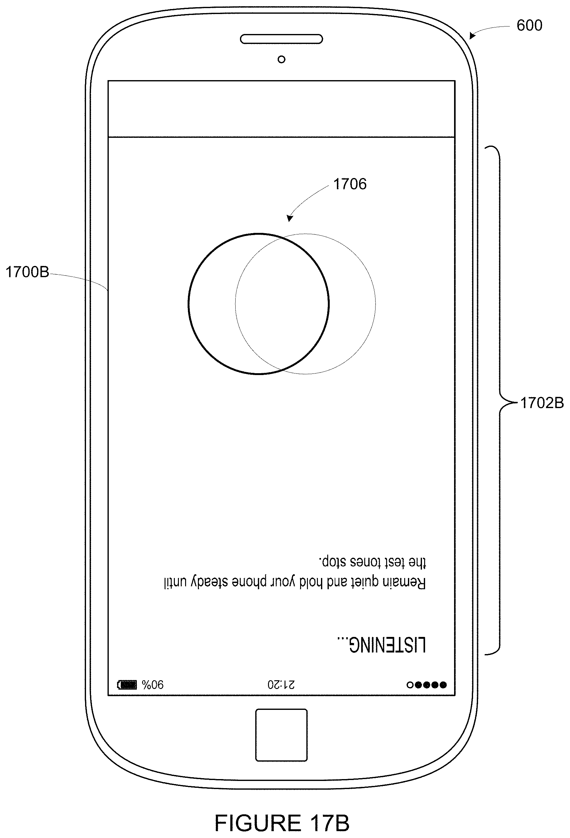
D00018

D00019
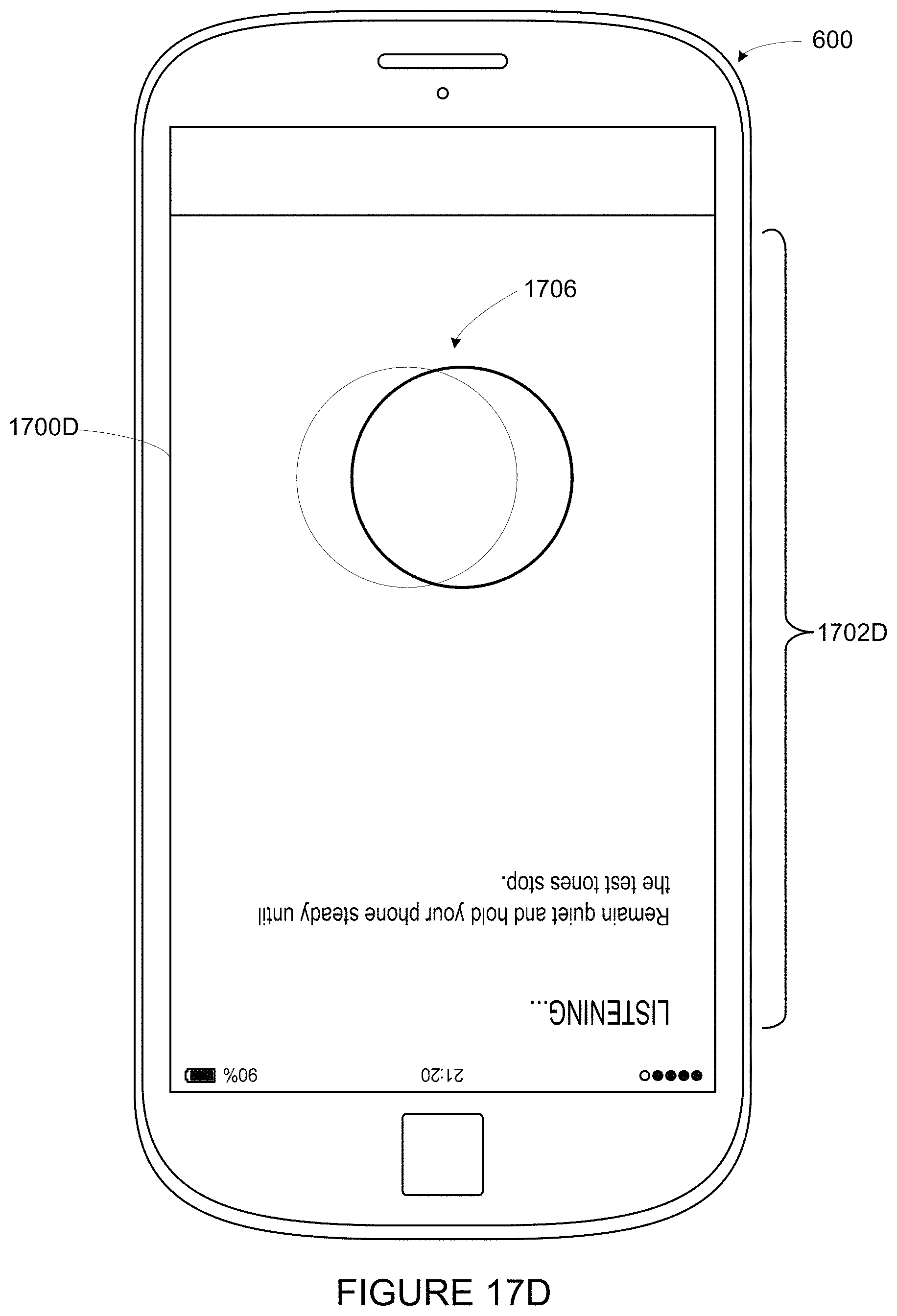
D00020

D00021

D00022

D00023

D00024

D00025
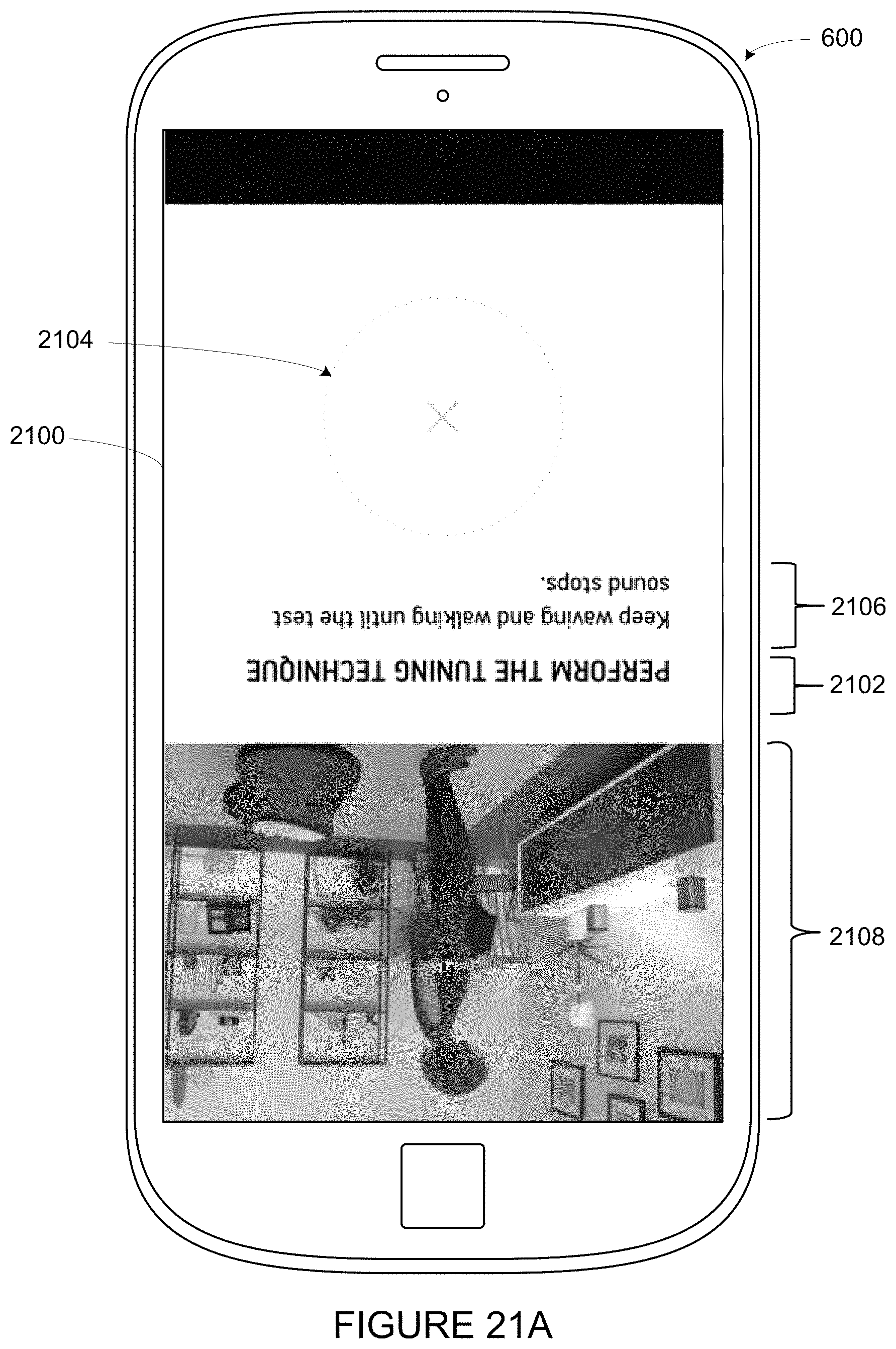
D00026

D00027
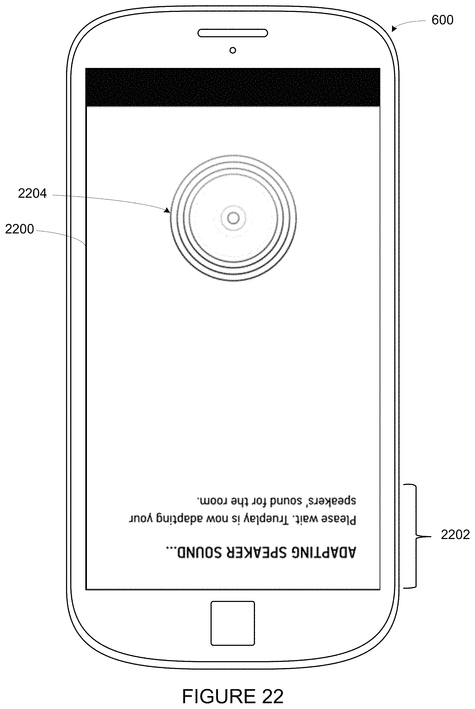
D00028
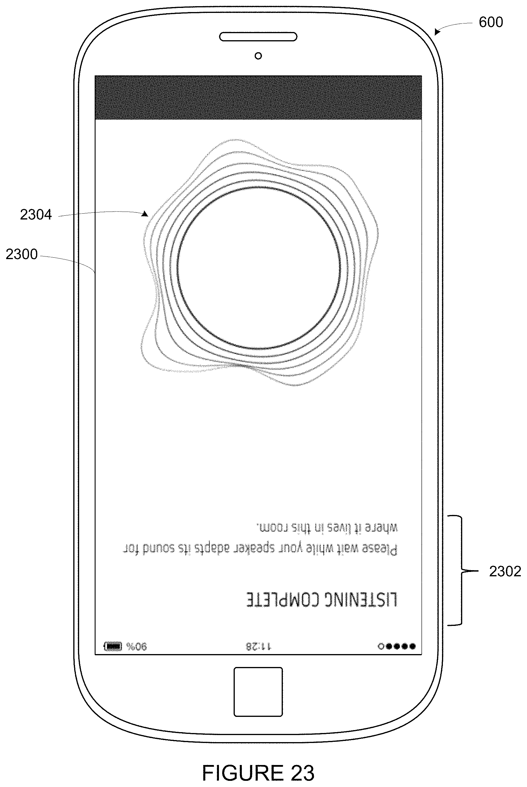
D00029

XML
uspto.report is an independent third-party trademark research tool that is not affiliated, endorsed, or sponsored by the United States Patent and Trademark Office (USPTO) or any other governmental organization. The information provided by uspto.report is based on publicly available data at the time of writing and is intended for informational purposes only.
While we strive to provide accurate and up-to-date information, we do not guarantee the accuracy, completeness, reliability, or suitability of the information displayed on this site. The use of this site is at your own risk. Any reliance you place on such information is therefore strictly at your own risk.
All official trademark data, including owner information, should be verified by visiting the official USPTO website at www.uspto.gov. This site is not intended to replace professional legal advice and should not be used as a substitute for consulting with a legal professional who is knowledgeable about trademark law.