Method of operating an energy recovery system
Heberer , et al. December 1, 2
U.S. patent number 10,852,071 [Application Number 16/029,838] was granted by the patent office on 2020-12-01 for method of operating an energy recovery system. This patent grant is currently assigned to CARRIER CORPORATION. The grantee listed for this patent is Carrier Corporation. Invention is credited to Eric W. Adams, Dwight H. Heberer.


| United States Patent | 10,852,071 |
| Heberer , et al. | December 1, 2020 |
Method of operating an energy recovery system
Abstract
A method of operating an energy recovery system includes providing a flow of fresh air from an energy recovery ventilator through a supply port into a component of a heating and cooling system. Stale air is blown from the component through a return port into the energy recovery ventilator, the return port including a shield configured to at least partially prevent fresh air flowing from the supply port into the component from recirculating through the return port.
| Inventors: | Heberer; Dwight H. (Brownsburg, IN), Adams; Eric W. (Manlius, NY) | ||||||||||
|---|---|---|---|---|---|---|---|---|---|---|---|
| Applicant: |
|
||||||||||
| Assignee: | CARRIER CORPORATION (Palm Beach
Gardens, FL) |
||||||||||
| Family ID: | 1000005214725 | ||||||||||
| Appl. No.: | 16/029,838 | ||||||||||
| Filed: | July 9, 2018 |
Prior Publication Data
| Document Identifier | Publication Date | |
|---|---|---|
| US 20180313614 A1 | Nov 1, 2018 | |
Related U.S. Patent Documents
| Application Number | Filing Date | Patent Number | Issue Date | ||
|---|---|---|---|---|---|
| 14074055 | Nov 7, 2013 | 10041743 | |||
| 61749658 | Jan 7, 2013 | ||||
| Current U.S. Class: | 1/1 |
| Current CPC Class: | F28F 9/0246 (20130101); F28D 21/0001 (20130101); F24F 12/006 (20130101); Y02B 30/56 (20130101) |
| Current International Class: | F28D 21/00 (20060101); F28F 9/02 (20060101); F24F 12/00 (20060101) |
References Cited [Referenced By]
U.S. Patent Documents
| 211332 | January 1879 | Kelly |
| 1975316 | October 1934 | Ferris |
| 2189895 | February 1940 | Fritz |
| 2439109 | April 1948 | Stout |
| 2570910 | October 1951 | Berry |
| 2814977 | December 1957 | Noll |
| 2828110 | March 1958 | Baker et al. |
| 2868108 | January 1959 | Petersen |
| 2973704 | March 1961 | Flanagan |
| 2995077 | August 1961 | Kitson |
| 3026789 | March 1962 | Mead |
| 3057288 | October 1962 | Papsdorf |
| 3250206 | May 1966 | Strouth |
| 3286479 | November 1966 | Nolan et al. |
| 3299796 | January 1967 | Toper et al. |
| 3440947 | April 1969 | Averill |
| 3666007 | May 1972 | Yoshino et al. |
| 3673945 | July 1972 | Rachlin et al. |
| 3772861 | November 1973 | Gunyou et al. |
| 3813214 | May 1974 | Alpine |
| 3842722 | October 1974 | Miller |
| 3926249 | December 1975 | Glancy |
| 3934798 | January 1976 | Goldsmith |
| 3945430 | March 1976 | Van Beukering et al. |
| 2400726 | May 1976 | Walter et al. |
| 3977466 | August 1976 | Johansson |
| 4022117 | May 1977 | Mallian |
| 4040477 | August 1977 | Garberick |
| 4044950 | August 1977 | Engeling et al. |
| 4100763 | July 1978 | Brody |
| 4117883 | October 1978 | Feldmann |
| 4142575 | March 1979 | Glancy |
| 4147303 | April 1979 | Talucci |
| 4149590 | April 1979 | Ospelt |
| 4171089 | October 1979 | Schossow |
| 4185685 | January 1980 | Giberson |
| 4206742 | June 1980 | Johnson |
| 4215814 | August 1980 | Ebert |
| 4217878 | August 1980 | Wieweck |
| 4241874 | December 1980 | Schossow |
| 4252181 | February 1981 | Kirchmeier |
| 4281522 | August 1981 | Bussjager |
| 4336748 | June 1982 | Martin et al. |
| 4377201 | March 1983 | Kruse et al. |
| 4389853 | June 1983 | Hile |
| 4391616 | July 1983 | Imamura |
| 4397157 | August 1983 | Keuch |
| 4408716 | October 1983 | Rockwell |
| 4462459 | July 1984 | Schmidlin |
| 4478056 | October 1984 | Michaels, Jr. |
| 4495986 | January 1985 | Clark et al. |
| 4497361 | February 1985 | Hajicek |
| 4503902 | March 1985 | Zolik |
| 4512392 | April 1985 | van Ee et al. |
| 4512393 | April 1985 | Maendel |
| 4513809 | April 1985 | Schneider |
| 4519539 | May 1985 | Bussjager et al. |
| 1537035 | August 1985 | Stiles |
| 4537035 | August 1985 | Stiles |
| 4550773 | November 1985 | Martin |
| 4676073 | June 1987 | Lawrence |
| 4727931 | March 1988 | Berner |
| 4742957 | May 1988 | Mentuch |
| 4757744 | July 1988 | Bouvot |
| 4759196 | July 1988 | Davis |
| 4799539 | January 1989 | Atkin et al. |
| 4823679 | April 1989 | Robbins |
| 4834285 | May 1989 | Besik |
| 4852640 | May 1989 | Besik |
| 4865118 | September 1989 | Moland |
| 4887438 | December 1989 | Meckler |
| 4909307 | March 1990 | Besik |
| 4924934 | May 1990 | Steele |
| 4952283 | August 1990 | Besik |
| 5002118 | March 1991 | Olmstead et al. |
| 5063835 | November 1991 | Rockx |
| 5183098 | February 1993 | Chagnot |
| 5238052 | August 1993 | Chagnot |
| 5295905 | March 1994 | Simple |
| 5301744 | April 1994 | Derks |
| 5344287 | September 1994 | Schaefer |
| 5417278 | May 1995 | Pipher et al. |
| 5423187 | June 1995 | Fournier |
| 5431215 | July 1995 | Davis |
| 5447037 | September 1995 | Bishop et al. |
| 5485878 | January 1996 | Derks |
| 5490557 | February 1996 | Taylor |
| 5497823 | March 1996 | Davis |
| 5548970 | August 1996 | Cunningham, Jr. et al. |
| 5617913 | April 1997 | DeGregoria et al. |
| 5632334 | May 1997 | Grinbergs et al. |
| 5636786 | June 1997 | Daneshvar et al. |
| 5675908 | October 1997 | Barnes |
| 5724898 | March 1998 | Von Bockh et al. |
| 5761908 | June 1998 | Oas et al. |
| 5826641 | October 1998 | Bierwirth et al. |
| 5855320 | January 1999 | Grinbergs |
| 5937667 | August 1999 | Yoho, Sr. |
| 5953320 | September 1999 | Williamson et al. |
| 5953926 | September 1999 | Dressler |
| 6039109 | March 2000 | Chagnot et al. |
| 6083300 | July 2000 | McFadden |
| 6141979 | November 2000 | Dunlap |
| 6168380 | January 2001 | Weigand |
| 6257317 | July 2001 | DeGregoria et al. |
| 6267536 | July 2001 | Adachi et al. |
| 6328095 | December 2001 | Felber et al. |
| 6355091 | March 2002 | Felber et al. |
| 6367703 | April 2002 | Morosas |
| 6450244 | September 2002 | Bassilakis |
| 6508066 | January 2003 | Mierins et al. |
| 6574950 | June 2003 | Nash |
| 6575228 | June 2003 | Ragland et al. |
| 6612267 | September 2003 | West |
| 6619063 | September 2003 | Brumett |
| 6644049 | November 2003 | Alford |
| 6675601 | January 2004 | Ebara |
| 6684653 | February 2004 | Des Champs et al. |
| 6820681 | November 2004 | Ohgami et al. |
| 6855050 | February 2005 | Gagnon et al. |
| 6889750 | May 2005 | Lagace et al. |
| 6966356 | November 2005 | Yeung |
| 6997006 | February 2006 | Kameyama et al. |
| 7028752 | April 2006 | Palffy et al. |
| 7059385 | June 2006 | Mailala |
| 7090000 | August 2006 | Taylor |
| 7150314 | December 2006 | Moffitt |
| 7188666 | March 2007 | Lee et al. |
| 7316261 | January 2008 | Cho et al. |
| 7337752 | March 2008 | Boros et al. |
| 7400501 | July 2008 | Bartell et al. |
| 7441586 | October 2008 | Chung et al. |
| 7445038 | November 2008 | Liu |
| 7455038 | November 2008 | Sic et al. |
| 7484381 | February 2009 | Lattanzio |
| 7565923 | July 2009 | Liu et al. |
| 7575178 | August 2009 | Loewen et al. |
| 7601206 | October 2009 | Call et al. |
| 7802443 | September 2010 | Wetzel |
| 7841381 | November 2010 | Chagnot et al. |
| 7878236 | February 2011 | Breen |
| 7900315 | March 2011 | Cunningham |
| 8157891 | April 2012 | Montie et al. |
| 8162042 | April 2012 | Haglid |
| 8235093 | August 2012 | Grinbergs |
| 8276892 | October 2012 | Narikawa et al. |
| 8381804 | February 2013 | Slaughter |
| 8479440 | July 2013 | Demonte et al. |
| 8590602 | November 2013 | Fernandez |
| 8621884 | January 2014 | Stammer et al. |
| 8702483 | April 2014 | Weng et al. |
| 8720109 | May 2014 | O'Brien et al. |
| 9835353 | December 2017 | McKie et al. |
| 10041743 | August 2018 | Heberer |
| 10760856 | September 2020 | Heberer |
| 2001/0018964 | September 2001 | DeGregoria et al. |
| 2001/0052240 | December 2001 | Kim et al. |
| 2002/0036238 | March 2002 | Riley et al. |
| 2005/0103464 | May 2005 | Taylor |
| 2005/0115013 | June 2005 | Biere |
| 2005/0133204 | June 2005 | Gates et al. |
| 2005/0224591 | October 2005 | Wolfson |
| 2005/0236150 | October 2005 | Chagnot et al. |
| 2006/0021375 | February 2006 | Wetzel et al. |
| 2006/0114637 | June 2006 | Ashworth |
| 2006/0252363 | November 2006 | Charlebois et al. |
| 2007/0084586 | April 2007 | Poirier |
| 2007/0205297 | September 2007 | Finkam et al. |
| 2007/0261558 | November 2007 | Ashworth |
| 2008/0035472 | February 2008 | Lepage |
| 2008/0047544 | February 2008 | Han |
| 2008/0250800 | October 2008 | Wetzel |
| 2008/0271874 | November 2008 | Gietzen |
| 2009/0114369 | May 2009 | Kammerzell |
| 2009/0133851 | May 2009 | Caldwell |
| 2010/0186927 | July 2010 | Gietzen |
| 2010/0198411 | August 2010 | Wolfson |
| 2010/0307175 | December 2010 | Teige et al. |
| 2011/0088417 | April 2011 | Kayser |
| 2011/0146941 | June 2011 | Benoit et al. |
| 2011/0155343 | June 2011 | Boudreau |
| 2011/0303389 | December 2011 | Knuth |
| 2012/0168119 | July 2012 | Dunnavant |
| 2012/0193820 | August 2012 | Montie et al. |
| 2012/0216558 | August 2012 | Dempsey et al. |
| 2013/0017774 | January 2013 | Zorzit |
| 2013/0087302 | April 2013 | McKie et al. |
| 2013/0092344 | April 2013 | Perez et al. |
| 2013/0092345 | April 2013 | McKie et al. |
| 2013/0092346 | April 2013 | McKie et al. |
| 2013/0095744 | April 2013 | McKie et al. |
| 2013/0105104 | May 2013 | Wiley |
| 2013/0116951 | May 2013 | McKie et al. |
| 2013/0124111 | May 2013 | McKie et al. |
| 2013/0225060 | August 2013 | Heberer et al. |
| 2013/0248154 | September 2013 | Haglid |
| 2014/0138076 | May 2014 | Heberer et al. |
| 2014/0190656 | July 2014 | Heberer |
| 2014/0190657 | July 2014 | Heberer et al. |
| 2014/0190670 | July 2014 | Dempsey et al. |
| 2014/0273800 | September 2014 | Carlyon |
| 2014/0374065 | December 2014 | Heberer et al. |
| 2015/0176913 | June 2015 | Buckrell |
| 2015/0216298 | August 2015 | Delorean et al. |
| 2015/0285524 | October 2015 | Saunders |
| 2017/0211826 | July 2017 | Mariotto |
| 2019/0063780 | February 2019 | Puttagunta |
| 2019/0154270 | May 2019 | Florian |
| 2019/0277576 | September 2019 | Toubiana |
| 101362159 | Feb 2009 | CN | |||
| 157562 | Jan 1921 | GB | |||
| 61130753 | Jun 1986 | JP | |||
| 62255980 | Nov 1987 | JP | |||
| 0692843 | Nov 1994 | JP | |||
| 200035239 | Feb 2000 | JP | |||
| 20100104465 | Sep 2010 | KR | |||
Attorney, Agent or Firm: Cantor Colburn LLP
Parent Case Text
CROSS-REFERENCE TO RELATED APPLICATIONS
This application is a divisional application of U.S. patent application Ser. No. 14/074,055 filed Nov. 7, 2013, which claims the benefit of an earlier filing date of U.S. Patent Application No. 61/749,658, filed Jan. 7, 2013 the contents of which are incorporated by reference herein in their entirety.
Claims
What is claimed is:
1. A method of operating an energy recovery system comprising: flowing a flow of fresh air from an energy recovery ventilator through a supply port into a circulation air blower compartment of a heating and cooling system for use by the circulation air blower compartment; flowing stale air from the circulation air blower compartment through a return port into the energy recovery ventilator; providing a shield at the return port, the shield having a triangular cross-section in a plane parallel to a side wall of a housing of the energy recovery ventilator in which the report port is disposed; and preventing, via the shield, the flow of fresh air from recirculating through the return port.
2. The method of claim 1, further comprising flowing the stale airflow around the shield, the shield configured to prevent reingestion of the flow of fresh air into the return port.
3. The method of claim 1, wherein the return port draws the flow of stale air from a lower perimeter of the circulation air blower compartment.
Description
BACKGROUND OF THE INVENTION
Embodiments relate generally to heat and mass exchangers and, more particularly, to an energy recovery ventilator ("ERV") that attaches directly to an existing furnace, fan coil or air handler and uses two duct connections for recovering energy from indoor air.
An ERV is generally used with a heating and cooling system to exhaust stale air from a stale air space to a fresh air space and bring in fresh air from the fresh air space to the stale air space while exchanging heat or cool energy, thereby reducing heating or cooling requirements. Typically, an ERV includes a heat and mass exchanger contained in a housing for exchanging heat or cool energy. The exchanger may be rotating or stationary. When the ERV is used with a heating and cooling, an outside air stream ducted from the outdoors and a stale room air stream from the return air duct or furnace, fan coil, or air handler separately enter the ERV and pass through the heat and mass exchanger. Within the heat and mass exchanger, energy from the stale room air stream is transferred either to or from the outside air stream. The outside air stream then exits the ERV to the supply air duct or furnace, fan coil, or air handler as a fresh air stream. The stale room air stream then exits the ERV to the outdoors through a duct as an exhaust room air stream.
Most residential ERVs are mounted on a wall or ceiling and generally require four duct pipes to exchange cool or heat energy with an air handler system. In an example, the outside air stream and the stale room air stream enter the housing through duct pipes connected to two air flow openings in the housing. The fresh air stream and the exhaust room air stream exit the housing through two other duct pipes connected to two other air flow openings in the housing. These ERVs are standalone heat and mass exchangers that are remotely mounted from the heating and cooling system and are not designed to be connected directly to a furnace or an air handler in a heating and cooling system. As connected to the heating and cooling system, this ERV is costly and cumbersome to install as it requires the installation of four separate duct pipes to carry each air stream to or from the fresh air or stale air spaces. Moreover, these ERVs require low voltage wall controls and an available power receptacle, which further complicates the installation process.
Other ERV's are configured to connect directly to a furnace or air handler blower compartment, eliminating the need for the four duct pipes. These ERV's, however, are prone to allow increased levels of stale air recirculation in the heating and cooling system.
BRIEF DESCRIPTION OF THE INVENTION
According to one aspect of the invention, an energy recovery system includes a heating and cooling system and an energy recovery ventilator operably connected to a component of the heating and cooling system. The energy recovery ventilator includes a supply port extending into the component to provide a supply of fresh airflow from the energy recovery ventilator to the component of the heating and cooling system for use by the component. A return port extends into the component configured to receive a flow of stale air from the component while minimizing ingestion of the fresh air flow from the component into the return port.
According to another aspect of the invention, a method of operating an energy recovery system includes flowing a flow of fresh air from an energy recovery ventilator through a supply port into a component of a heating and cooling system for use by the component. Stale air is flowed from the component through a return port into the energy recovery ventilator. The flow of fresh air is prevented from recirculating through the return port.
These and other advantages and features will become more apparent from the following description taken in conjunction with the drawings.
BRIEF DESCRIPTION OF THE DRAWINGS
The subject matter, which is regarded as the invention, is particularly pointed out and distinctly claimed in the claims at the conclusion of the specification. The foregoing and other features, and advantages of the invention are apparent from the following detailed description taken in conjunction with the accompanying drawings in which:
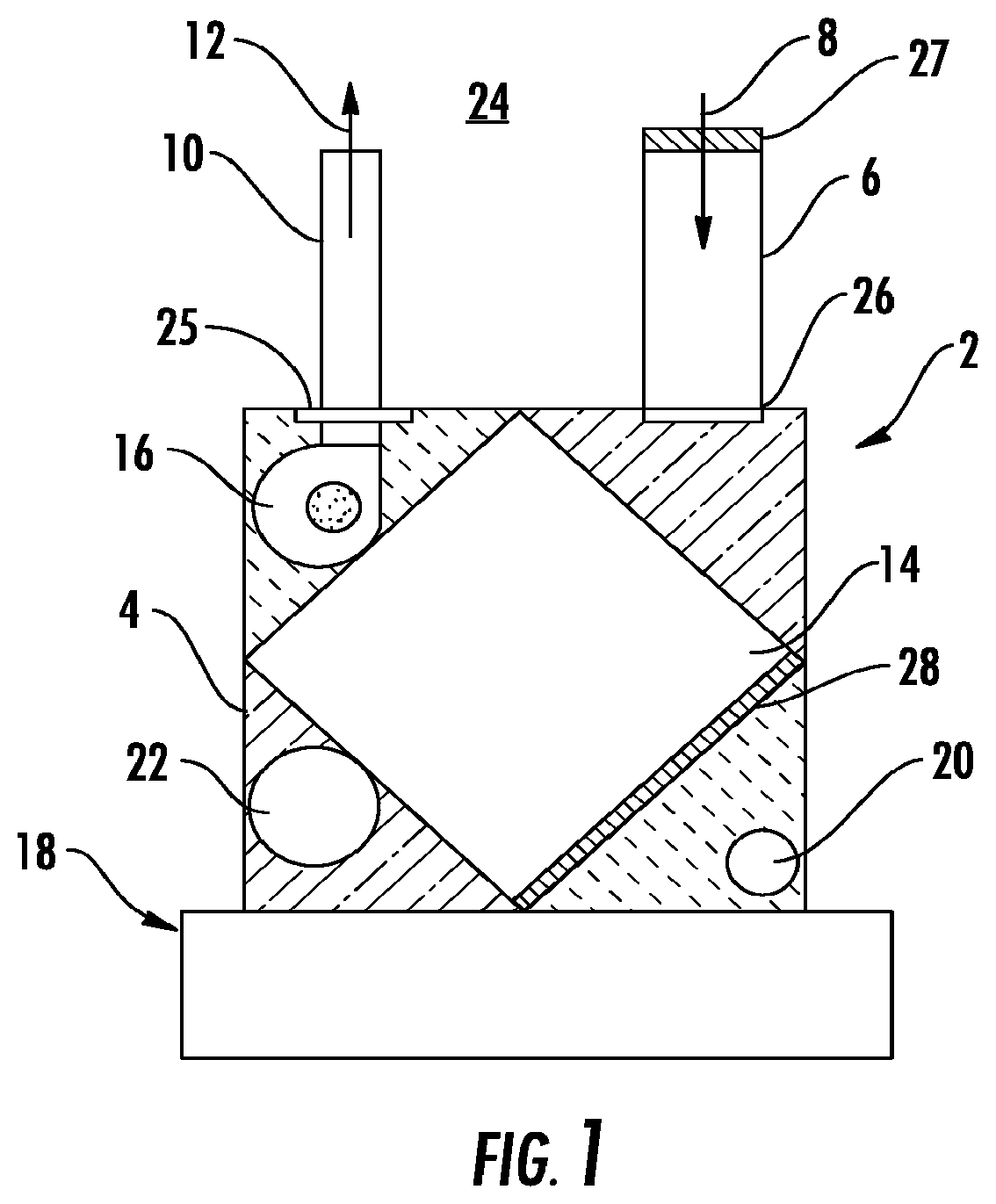
FIG. 1 is a view of an embodiment of an energy recovery ventilator (ERV);
FIG. 2 is a view of another embodiment of an ERV;
FIG. 3 illustrates an embodiment of an ERV connected to a heating and cooling system;
FIG. 4 illustrates embodiments of fresh air and return air ports between an embodiment of an ERV and a heating and cooling system;
FIG. 5 illustrates other embodiments of fresh air and return air ports between an embodiment of an ERV and a heating and cooling system;
FIG. 6 illustrates still other embodiments of fresh air and return air ports between an embodiment of an ERV and a heating and cooling system;
FIG. 7 illustrates yet other embodiments of fresh air and return air ports between an embodiment of and ERV and a heating and cooling system; and
FIG. 8 illustrates an alternate view of the embodiments of FIG. 7.
The detailed description explains embodiments of the invention, together with advantages and features, by way of example with reference to the drawings.
DETAILED DESCRIPTION OF THE INVENTION
An embodiment of an energy recovery ventilator ("ERV") for use with a heating and cooling system includes a generally rectangular housing that may be directly attached to an existing furnace/fan coil in the system. The ERV includes a fresh air intake duct and an exhaust air duct. In an embodiment, an outside air stream enters the ERV through the fresh air intake duct while stale conditioned air from an interior conditioned air space is exhausted through the exhaust air duct. The ERV includes a heat and mass exchange device for recovering energy from the stale conditioned air prior to exhausting the stale conditioned air to an outside air space. In an embodiment, the ERV may be used with a wall penetration that provides a simplified duct assembly for connecting the ducts to the outside air space. In an embodiment, the ERV may be electrically wired directly, via a wire line, to a power supply in the heating and cooling system in order to energize the ERV and eliminate providing a standalone power supply. In one non-limiting embodiment, a two-wire line may be used to simplify the electrical connection to the heating and cooling system. But, in other embodiments, any number of wire-lines may be used to electrically connect the ERV to the heating and cooling system. The ERV may also be connected to a furnace/fan coil controller in the heating and cooling system for controlling the operation of the ERV without requiring an additional dedicated controller for ERV control and operation.
Referring now to the drawings, FIGS. 1-2 illustrate an ERV 2 used in connection with a heating and cooling system 18 for circulating fresh air from the outdoors while recovering energy from stale conditioned air according to an embodiment of the invention. Particularly, the ERV 2 includes a generally rectangular housing 4 fitted with a fresh air intake duct 6 and an exhaust air duct 10. The fresh air intake duct 6 and exhaust air duct 10 are coupled to selectively movable dampers 25, 26, respectively. The dampers 25, 26 are selectively controllable by a furnace/fan coil controller (not shown) in response to signals such as, for example, signals indicative of temperature or humidity that are received from sensors inside the ERV 2 or inside the interior conditioned space. In some non-limiting examples, the dampers 25, 26 may be a valve or plate that stops or regulates the flow of air entering or exiting ERV 2 through the respective ducts 6, 10. The ERV 2 also includes a heat and mass exchange device 14 such as, in some non-limiting examples, a honeycomb heat exchanger or a brazed-plate heat exchanger for recovering energy from stale conditioned air. The stale conditioned air is received through a return port 20, which is in fluid communication with an air return duct coupled to the heating and cooling system 18. A fan 16 is coupled to the heat exchange device 14 in order to induce air movement through the heat exchange device 14 as well as induce to a positive air pressure in the furnace/fan coil of the heating and cooling system 18. In an embodiment, as shown with reference to FIG. 2, a fan or blower 29 may also be fluidly coupled to the fresh air intake duct to either induce air intake from an outdoor air space 24 or control the air flow rate entering the ERV 2 from the outdoor air space 24.
A filter element 27 is coupled to duct connection 6 in order to filter out any dust, debris, pollutants, or the like from the outside air stream 8. Additionally, in an embodiment, a filter element 28 is coupled to a return port 20 to filter an exhaust air stream 12 that is received from a return air duct that is in fluid communication with an interior conditioned air space. In another embodiment, a filter element, which is substantially similar to filter element 28, may be coupled to supply port 22 near or attached to the face of the heat exchanger 14 in order to filter the outside air stream 8. In operation, an outside air stream 8 from, for example, an outdoor air space 24 enters the ERV 2 through duct 6 while stale conditioned air from an interior conditioned air space is received by ERV 2 and exhausted as an exhaust air stream 12 through the exhaust air duct 10. Dampers 25, 26 control the air flow rate entering or exiting the ERV 2 or, alternatively, Dampers 25, 26 may be closed to bypass the ERV 2. The outside air stream 8 circulates through the heat exchange device 14 where energy exchange takes place within the heat exchange device 14. The extracted energy is transferred to the outside air stream 8 and it enters the heating and cooling system 18 as a fresh air stream through the supply port 22.
In an embodiment, as shown in FIGS. 1-2, the ERV 2 may be electrically wired directly, via a two-wire line, to the heating and cooling system 18 in order to energize ERV 2. The direct wiring eliminates need for providing an additional energizing power supply for energizing electrical components of the ERV 2. Also, the ERV may be selectively and electrically coupled to a controller (not shown) located in, for example, an electronics circuit board of the heating and cooling system 18. The controller (not shown) controls operation of the ERV 2 while also eliminating a need for an additional controller, thereby simplifying the installation as well as reducing the costs associated with installation. In an example, the controller may operate the ERV 2 while the furnace/fan coil air circulation blower is on in order to provide a desired ventilation rate through the heating and cooling system 18. In another example, the controller may operate the ERV 2 for a portion of each hour based on the desired ventilation rate and the air flow capacity of the ERV 2. In an embodiment, the controller includes a microprocessor preprogrammed with software programs that is stored in nonvolatile memory for executing algorithms to provide the ERV 2 with a variety of operation modes and control sequences as indicated above.
In another embodiment, shown in FIGS. 1-2, the ERV 2 may be directly attached to, for example, an air circulation blower compartment of a furnace/fan coil of the heating and cooling system 18 through bolts, screws, or the like. But, in another non-limiting embodiment, the ERV 2 may be attached to a return air duct of an air handler without departing from the scope of the invention. In an embodiment, the ERV 2 may be electrically connected to a power supply as well as to a controller of the furnace/fan coil, thereby eliminating a need for an additional power receptacle or a dedicated controller, respectively. In an embodiment, the heating and cooling system 18 may include fans (e.g., blowers, air handlers, and the like) to communicate air flow from an interior air space to the ERV 2. Other system components such as dampers, filters, additional fans, refrigeration and/or heating/dehumidification (e.g., economizer heat exchangers, heat rejection heat exchangers, and gas coolers/condensers), heat absorption heat exchangers (evaporator) may also be provided. In operation, outside air stream 8 enters the housing 2 through the duct connection 6 while stale conditioned air from the interior conditioned air space passes through the heat exchange device 14. The heat exchange device 14 extracts energy from the stale conditioned air and exhausts the stale conditioned air as an exhaust air stream 12 from the ERV 2. The outside air stream 8 circulates through the heat exchange device 14 where energy is transferred to the outside air steam 8 within the heat exchange device 14. The outside air stream 8 receives the extracted energy and enters the heating and cooling system 18 as a fresh air stream through the supply port 22. Further, stale conditioned air 12 is extracted from, in one non-limiting example, a return air duct that is directly connected to a conditioned air space. The stale conditioned air 12, driven by fan 16, enters the ERV 2 through return port 20, circulates through the heat exchange device 14, and exits the ERV 2 through duct connection 10.
FIG. 3 illustrates an elevation view of an ERV 2 that is in direct air flow communication with a furnace/fan coil 30 of system 18 according to another embodiment of the invention. As shown, the ERV 2 is sized to be directly connected to a circulation air blower compartment 32 of furnace/fan coil 30 and receives an air flow from the compartment 32 for energy recovery and recirculation to the interior conditioned air space 50. The ERV 2 includes a fresh air intake duct 6 and an exhaust air duct 10. The ERV 2 also includes a return port 20 and a supply port 22 that are in direct communication with the circulation air blower compartment 32. The ERV 2 is shown installed in a vertical orientation directly coupled to furnace/fan coil 30, which is also vertically oriented. But, in another embodiment, ERV 2 may be installed in a horizontal orientation in order to be coupled to a corresponding horizontally oriented heating and cooling system 18 without departing from the scope of the invention. A stale conditioned air stream 42 from an interior conditioned air space 50 enters system 18 through the return air duct 36. In an embodiment, an air cleaner such as, for example, an air purifier 38 is provided to filter the stale conditioned air stream 42 and communicate a filtered air stream 52 to the negative pressure chamber of circulation air blower compartment 32. In another embodiment, an air filter element (not shown) may be provided in lieu of the air purifier 38 in order to filter the stale conditioned air stream 42. The filtered air stream 52 enters the ERV 2 through return port 20 whereby energy is extracted by the heat and mass exchange device 14 (shown in FIGS. 1-2) prior to exiting the ERV 2 to the outdoor air space via duct 10. This extracted energy is transferred to an outside air stream 8 (shown in FIGS. 1-2) that enters the ERV 2 through intake duct 6. The outside air stream 8 (shown in FIGS. 1-2) is further communicated to the compartment 32 as a fresh air stream 46 through supply port 22. The fresh air stream 46 mixes with the filtered air stream 52 in the compartment 32. The circulation air blower 33 creates a positive pressure in a furnace/fan coil compartment 35. The positive pressure overcomes the negative pressure in the circulation air blower compartment 32 and forces the mixed air from compartment 32 through the evaporator coil compartment 34 for heat-exchange within the evaporator coil compartment 34. The mixed air is forced out of evaporator coil compartment 34 and through the air supply duct 40 as conditioned filtered air 48 in order to condition the interior conditioned air space 50. It is to be appreciated that the ERV 2 mounts directly to the furnace/fan coil 30 in order to exhaust filtered air stream 52 from air blower compartment 32 while overcoming the negative static pressure in the blower air compartment 32.
Referring to FIG. 4, an embodiment of a supply port 22 and return port 20 is shown. The supply port 22 and the return port 20 extend through the ERV housing 4 and into the blower compartment 32, and are secured to one or both of the housing 4 or the blower compartment 32 by, for example, a snap fit. Alternatively, the supply port 22 and/or the return port 20 are secured to the housing 4 or the blower compartment 32 by fasteners such as screws, pins or the like. The ports 20 and 22 shown in FIG. 4 have are configured to direct flow in a selected direction and have, for example, an elbow-shaped cross-section. If the selected direction is changed, the flow may be redirected by rotating the ports 20 and 22 in openings through which they extend. The ports 20 and 22 are positioned to reduce recirculation of stale air through the heating and cooling system 18, either through their orientation as above, or through their position in the ERV housing 4, or both. As shown in FIG. 4, the supply port 22 and the return port 20 are oriented to ensure that the fresh air stream 46 flowing through the supply port 22 into the blower compartment is directed away from the return port 20 to minimize reingestion of fresh air stream 46 into the return port 20, and maximizing filtered stale airstream 52 flowed through the return port 20 from the blower compartment 32 and into the ERV 2.
In other embodiments, as shown in FIG. 5, the supply port 22 and the return port 20 are triangular in cross-section. The triangular cross-section increases the flow path size for the fresh air stream 46 and the filtered stale airstream 52 to and from the blower compartment 32. Increasing the flowpath size beneficially increases a rate of which the fresh air stream 46 can be delivered to the blower compartment 32 as well as increasing circulation of the filtered stale airstream 52 from the blower compartment 32 into the ERV 2 via the return port 20. As shown in FIG. 6, in some embodiments the return port 20 includes a shield 70 secured to the return port 20. The shield 70 is also triangular in shape and includes a shield opening 72 facing substantially downward into the blower compartment 32. The shield 70 having the downward-facing shield opening 72 reduces recirculation of the fresh air stream 46 into the return port 20 by drawing from a lower perimeter 74 of the blower compartment 32, reducing opportunities for the fresh air stream 46, which is urged substantially upward by the blower 33.
Referring now to FIG. 7, in some embodiments, the ERV 2 is operably connected to a return air duct 36, as an alternative to being connected to the blower compartment 32. In the embodiment of FIG. 7, a stale air stream 42 is directed through the return air duct 36 toward the ERV 2. At least a portion of the stale airstream 42 is directed into the return port 20 of the ERV 2 and into the ERV 2, while the fresh airstream 46 is directed into the return air duct 36 through the supply port 22 toward the air purifier 38 and the blower compartment 32. The supply port 22 and return port 20 are configured and located to prevent reingestion of the fresh airstream 46 into the return port 20. As shown in the embodiment of FIG. 7, the return port 20 is located upstream of the supply port 22 in the return air duct 36. Further, in some embodiments, as shown in FIG. 8, the return port 20 may include a shield 70 with an upstream-facing shield opening 72 to further restrict recirculation of the fresh airstream 46 into the return port 20.
While the invention has been described in detail in connection with only a limited number of embodiments, it should be readily understood that the invention is not limited to such disclosed embodiments. Rather, the invention can be modified to incorporate any number of variations, alterations, substitutions or equivalent arrangements not heretofore described, but which are commensurate with the spirit and scope of the invention. Additionally, while various embodiments of the invention have been described, it is to be understood that aspects of the invention may include only some of the described embodiments. Accordingly, the invention is not to be seen as limited by the foregoing description, but is only limited by the scope of the appended claims.
* * * * *
D00000
D00001
D00002
D00003
D00004
D00005
D00006
D00007
D00008
XML
uspto.report is an independent third-party trademark research tool that is not affiliated, endorsed, or sponsored by the United States Patent and Trademark Office (USPTO) or any other governmental organization. The information provided by uspto.report is based on publicly available data at the time of writing and is intended for informational purposes only.
While we strive to provide accurate and up-to-date information, we do not guarantee the accuracy, completeness, reliability, or suitability of the information displayed on this site. The use of this site is at your own risk. Any reliance you place on such information is therefore strictly at your own risk.
All official trademark data, including owner information, should be verified by visiting the official USPTO website at www.uspto.gov. This site is not intended to replace professional legal advice and should not be used as a substitute for consulting with a legal professional who is knowledgeable about trademark law.