Running wire rope and method of manufacturing same
Watanabe , et al. December 1, 2
U.S. patent number 10,851,493 [Application Number 16/295,002] was granted by the patent office on 2020-12-01 for running wire rope and method of manufacturing same. This patent grant is currently assigned to TOKYO ROPE MANUFACTURING CO., LTD.. The grantee listed for this patent is TOKYO ROPE MANUFACTURING CO., LTD.. Invention is credited to Kaori Kanamori, Jun Takeuchi, Shigeki Watanabe.


| United States Patent | 10,851,493 |
| Watanabe , et al. | December 1, 2020 |
Running wire rope and method of manufacturing same
Abstract
A wire rope formed from a resin core and six strands, the resin core having an inner core with a circular cross section and an outer layer built up on the periphery thereof. The outer layer has a melting temperature lower than that of the inner core. The six strands are twisted together helically on the periphery of the resin core in an intertwining die in such a state that gaps are assured between the strands. The resulting wire rope is heated in a heating unit at a temperature higher than the melting temperature of the outer layer but lower than the melting temperature of the inner core. The wire rope is formed by subsequently compressing the six strands from the periphery thereof in a compressing die. The molten outer layer is hardened by natural cooling, after which the wire rope is taken up.
| Inventors: | Watanabe; Shigeki (Tokyo, JP), Kanamori; Kaori (Tokyo, JP), Takeuchi; Jun (Tokyo, JP) | ||||||||||
|---|---|---|---|---|---|---|---|---|---|---|---|
| Applicant: |
|
||||||||||
| Assignee: | TOKYO ROPE MANUFACTURING CO.,
LTD. (Tokyo, JP) |
||||||||||
| Family ID: | 1000005214206 | ||||||||||
| Appl. No.: | 16/295,002 | ||||||||||
| Filed: | March 7, 2019 |
Prior Publication Data
| Document Identifier | Publication Date | |
|---|---|---|
| US 20190203412 A1 | Jul 4, 2019 | |
Related U.S. Patent Documents
| Application Number | Filing Date | Patent Number | Issue Date | ||
|---|---|---|---|---|---|
| PCT/JP2016/076926 | Sep 13, 2016 | ||||
| Current U.S. Class: | 1/1 |
| Current CPC Class: | D07B 1/0686 (20130101); D07B 1/0693 (20130101); D07B 1/16 (20130101); D07B 1/005 (20130101); D07B 2201/2065 (20130101); D07B 2201/1032 (20130101); D07B 2201/2019 (20130101); D07B 2205/2003 (20130101); D07B 2201/108 (20130101) |
| Current International Class: | D07B 1/06 (20060101); D07B 1/16 (20060101); D07B 1/00 (20060101) |
References Cited [Referenced By]
U.S. Patent Documents
| 3530661 | September 1970 | Thomen |
| 3705489 | December 1972 | Smollinger |
| 3778994 | December 1973 | Humphries |
| 5797254 | August 1998 | Walton |
| 6317540 | November 2001 | Foulger |
| 6563054 | May 2003 | Damien et al. |
| 8176718 | May 2012 | Ridge et al. |
| 8943789 | February 2015 | Takeuchi |
| 9162849 | October 2015 | Mitsui |
| 9309620 | April 2016 | Amils |
| 9896307 | February 2018 | Mitsui |
| 9902594 | February 2018 | Mitsui |
| 2012/0180926 | July 2012 | Rebouillat |
| 2013/0318937 | December 2013 | Takeuchi |
| 2018/0251940 | September 2018 | Carter |
| 2018/0362300 | December 2018 | Mitsui |
| 689098 | Sep 1998 | CH | |||
| 2703670 | Aug 1978 | DE | |||
| 2015139818 | Aug 2015 | JP | |||
| WO-2012056529 | May 2012 | WO | |||
| 2014053601 | Apr 2014 | WO | |||
Other References
|
Machine Translation of DE 2703670 A1, Retrieved Jun. 2020. cited by examiner. |
Primary Examiner: Hurley; Shaun R
Attorney, Agent or Firm: Dickinson Wright PLLC
Parent Case Text
CROSS-REFERENCE TO RELATED APPLICATIONS
This application is a Continuation Application of PCT Application No. PCT/JP2016/076926, filed Sep. 13, 2016, the entire disclosure of the application being considered part of the disclosure of this application and hereby incorporated by reference.
Claims
What is claimed is:
1. A method of manufacturing a running wire rope, comprising: helically twisting together a plurality of strands, in a state in which gaps are assured between the strands, around a resin core in which a resin outer layer has been built up on the periphery of a resin inner core having a circular cross section, said outer layer having a melting temperature lower than that of said inner core; heating at a temperature higher than the melting temperature of the outer layer and lower than the melting temperature of the inner core, thereby melting the outer layer; compressing the plurality of strands from the periphery thereof; and hardening the outer layer.
2. A method of manufacturing a running wire rope according to claim 1, including compressing the plurality of strands to thereby cause the strands to bite into the surface of the inner core to a depth of not more than 10% of the outer diameter of the inner core.
3. A method of manufacturing a running wire rope according to claim 1, including hardening the outer layer by natural cooling or forced cooling.
4. A running wire rope having a center, the running wire rope comprising: a resin core, provided at the center of the running wire rope, wherein said resin core includes a resin inner core having a circular cross section and a resin outer layer built up on the periphery of a resin inner core, said outer layer having a melting temperature lower than that of said inner core; and a plurality of strands twisted together helically on the periphery of said resin core; wherein said plurality of strands are in contact with said inner core or bite into said inner core, and gaps between said plurality of strands as well as valleys between wires on the surface of the strands that face the gaps are filled by hardened resin constituting said outer layer, which has a shape conforming to the shape of the gaps and the shape of the valleys.
5. The running wire rope according to claim 4, wherein a difference in melting temperature between said inner core and said outer layer is equal to or greater than 15.degree. C.
6. The running wire rope according to claim 4, wherein the melting temperature of said outer layer is equal to or greater than 80.degree. C.
7. The running wire rope according to claim 4, wherein said outer layer has a melt flow rate of not more than 30 g/10 min.
Description
TECHNICAL FIELD
This invention relates to a running wire rope, namely a wire rope for a running cable used, for example, as the running cable for a gondola, the running cable for an elevator and as the running cable of other facilities or equipment.
BACKGROUND OF THE INVENTION
A running wire rope used as a running cable sustains repeated bending under tension. In a case where a fiber core is used as the core material of a running wire rope, the diameter of the fiber core undergoes a reduction in diameter and so does the diameter of the wire rope itself. When the diameter of the wire rope decreases, the wire rope elongates in the longitudinal direction. If a running wire rope used in a gondola or elevator or the like sustains an excessive amount of elongation in the longitudinal direction, the wire rope must be cut off by the amount of such elongation.
BRIEF DESCRIPTION OF THE INVENTION
An object of the present invention is to markedly suppress contact between strands as well as suppress a decrease in diameter and prevent elongation of a wire rope during use thereof.
A method of manufacturing a running wire rope according to the present invention is characterized by helically twisting together a plurality of strands, in a state in which gaps are assured between the strands, around a resin core in which a resin outer layer has been built up on the periphery of a resin inner core having a circular cross section, the outer layer having a melting temperature lower than that of the inner core; heating at a temperature higher than the melting temperature of the outer layer and lower than the melting temperature of the inner core, thereby melting the outer layer; compressing the plurality of strands from the periphery thereof; and hardening the outer layer.
The resin core is constituted by an inner core, which is made of resin, and an outer layer, which is made of resin, that has been built up on the periphery of the inner core and that has a melting temperature lower than that of the inner core. Therefore, when heat is applied at a temperature higher than the melting temperature of the outer layer and lower than the melting temperature of the inner core, only the outer layer melts without causing the melting of the inner core. A plurality of strands are twisted together helically in a state in which gaps are assured between the strands. When the plurality of strands are compressed from the periphery thereof with the outer layer in the molten state, the molten outer layer flows diametrically outward and penetrates into the gaps between the plurality of strands being compressed inward. The molten outer layer penetrates also into valleys between wires on the surface of strands that face the gaps. Thereafter the molten outer layer is hardened by passage through a cooling step (natural or forced cooling). The resin of the outer layer hardens while maintaining a shape that conforms to the shape of the gaps between the strands following the compression thereof and the shape of the valleys between wires on the surface of strands that face the gaps.
In accordance with the present invention, the gaps between the plurality of strands and the valleys between wires on the surface of strands that face the gaps are filled by the resin of the fluidic or molten outer layer. As a result, mutually adjacent strands will not come into direct contact and fretting wear can be prevented. Further, it is possible to reduce deformation of the wire rope when the wire rope is bent by being engaged with a sheave. Furthermore, since the inner core is not melted by heating, a wire rope is provided in which the plurality of strands compressed from the periphery thereof are supported by the inner core so that there will be no reduction in diameter even with continuous use and, hence, little or almost no elongation.
In an embodiment, the plurality of strands are compressed to such a degree that the strands bite into the inner core. Preferably, the plurality of strands are compressed and caused to bite into the surface of the inner core to a depth of not more than 10% of the outer diameter of the inner core. By compressing the plurality of strands comparatively strongly, elongation of the wire rope can be markedly suppressed. By stopping the strands from biting in to a depth of not more than 10% with respect to the outer diameter of the inner core, the occurrence of a large amount of elongation owing to a decline in the strength of the core can be prevented.
A running wire rope according to the present invention comprises: a resin core in which a resin outer layer has been built up on the periphery of a resin inner core having a circular cross section, the outer layer having a melting temperature lower than that of the inner core; and a plurality of strands twisted together helically on the periphery of the resin core; wherein the plurality of strands are in contact with the inner core or bite into the inner core, and the gaps between the plurality of strands as well as the valleys between wires on the surface of strands that face the gaps are filled by hardened resin constituting the outer layer, which has a shape conforming to the shape of the gaps and the shape of the valleys. According to the present invention, there is provided a wire rope in which fretting wear will not readily occur, in which there is little deformation when the wire rope is bent by being engaged with a sheave, and in which there will be no reduction in diameter even with continuous use and, hence, little or almost no elongation.
In one embodiment, a difference in melting temperature between the inner core and the outer layer is equal to or greater than 15.degree. C., to allow only the outer layer to melt assuredly without causing melting of the inner core.
In an embodiment, the melting temperature of the outer layer is equal to or greater than 80.degree. C., to allow melting or softening of the outer layer to be suppressed during use or transport of the wire rope.
In another embodiment, the outer layer has a melt flow rate of not more than 30 g/10 min, to allow dripping of the outer layer when the outer layer is heated and melted to be prevented.
BRIEF DESCRIPTION OP THE DRAWINGS
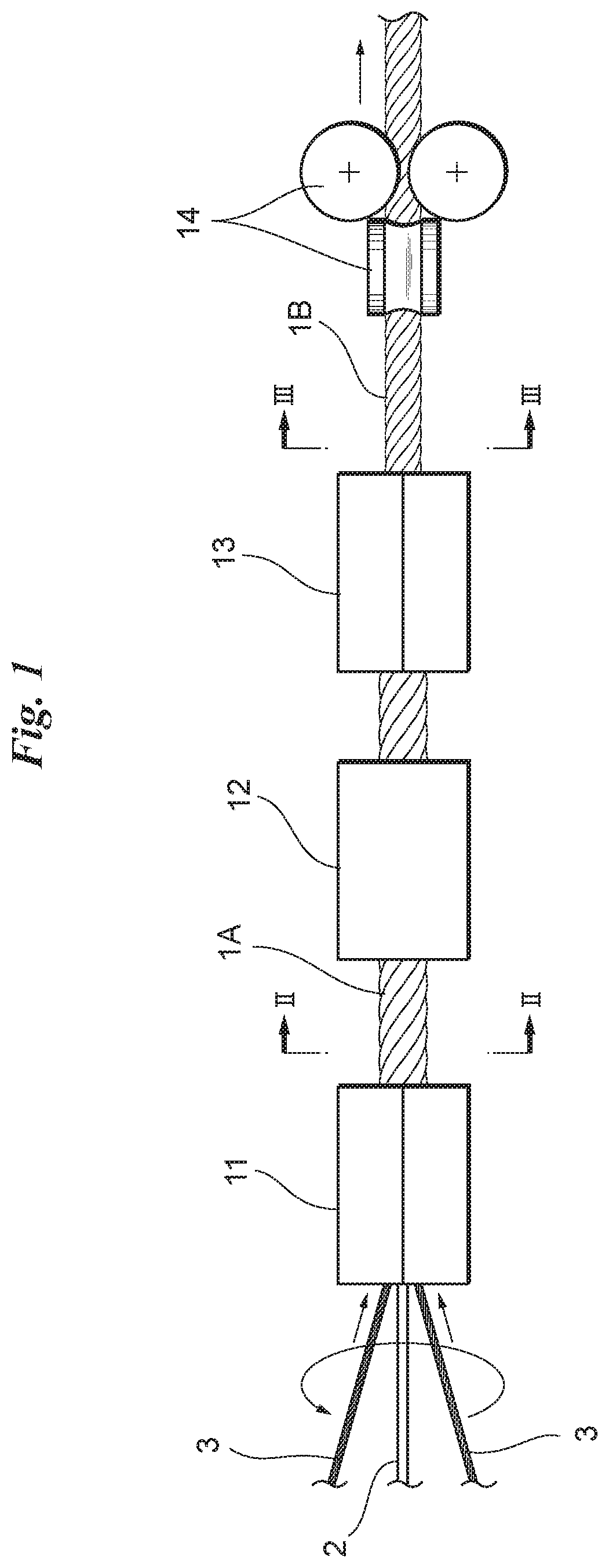
FIG. 1 diagrammatically illustrates a wire rope manufacturing apparatus;
FIG. 2 is a cross-sectional view of a wire rope in the course of manufacture; and
FIG. 3 is a cross-sectional view of a completed wire rope.
DETAILED DESCRIPTION OF THE INVENTION
FIG. 1 diagrammatically illustrates a wire rope manufacturing apparatus with the wire rope being formed and FIGS. 2 and 3 are cross-sectional views of a wire rope taken along lines II-II and of FIG. 1, respectively.
With reference to FIG. 1, a single resin core 2 and six strands 3 sent from a wire stranding machine (not shown) are fed to an intertwining die 11.
With reference to FIG. 2, the resin core 2 is composed of a high-density polyethylene inner core 2a having a circular cross section, and a low-density polyethylene outer layer 2b, which has an annular cross section, obtained by being built up on (applied as a coating to) the outer peripheral surface of the core 2a to a uniform thickness. The core 2a is fabricated in a solid state as by extrusion molding or pultrusion molding. The outer layer 2b is built up on (applied as a coating to) the outer peripheral surface of the core 2a to a uniform thickness as by extrusion lamination.
The melting point (melting temperature) of the high-density polyethylene constituting the inner core 2a is on the order of 120 to 140.degree. C., and the melting point of the low-density polyethylene constituting the outer layer 2b is on the order of 95 to 115.degree. C. Thus the melting point of the outer layer 2b is lower than that of the inner core 2a. Resins of other types having a difference in melting point may be selected as the inner core 2a and outer layer 2b, respectively. Preferably, two types of thermoplastic resin having a difference in melting point equal to or greater than 15.degree. C. are selected as the respective resins constituting the inner core 2a and outer layer 2b. Further, in order to suppress melting or softening of the outer layer 2b during use or transport of the wire rope, a resin having a melting point equal to or greater than 80.degree. C. preferably is selected as the outer layer 2b. A polyolefin resin imparted with flexibility and weather resistance is suitable as the resin constituting the inner core 2a and outer layer 2b.
Furthermore, the outer layer 2b is adjusted in such a manner that the melt flow rate, which is measured according to ISO 1133 (JIS K 7210), will be not more than 30 g/10 min, preferably not more than 20 g/10 min. For example, the melt flow rate of the outer layer 2b can be adjusted by changing the molecular weight of the resin or by mixing in an additive, such a filler, that adjusts the melt viscosity.
Each strand 3 in this embodiment is obtained by twisting together a total of 31 steel wires in Warrington-Seale form. The number of steel wires that constitute the strand 3, the structure of the twisted wires and the number of strands 3 that constitute the wire rope can be modified appropriately in accordance with such factors as the tensile strength sought for the wire rope.
With reference to FIG. 1, the resin core 2 and the six strands 3 are gathered together and the six strands 3 are twisted helically around the resin core 2 in the intertwining die 11.
A jig may be placed at the entrance to the intertwining die 11 for the purpose of arranging the six strands 3 in helical form around the resin core 2 while assuring gaps at equal intervals. With reference to FIG. 2, a wire rope 1A which has passed through the intertwining die 11 takes on a state in which the six strands 3 have been twisted into helical form with gaps assured between mutually adjacent strands 3 around the resin core 2.
The wire rope 1A next proceeds to a heating unit 12.
The heating unit 12 used is, for example, one having a coil in which temperature is capable of being controlled by induction heating. When passing through the coil possessed by the heating unit 12, the wire rope 1A (strands 3) is heated uniformly from the periphery thereof.
The heat applied by the heating unit 12 is performed at a temperature higher than the above-mentioned melting point of the outer layer 2b but lower than the melting point of the inner core 2a. As a result, only the outer layer 2b is caused to melt; the inner core 2a can remain solid as is due to the fact that the inner core 2a and outer layer 2b have melting points that differ by 15.degree. C. or more, causing only the outer layer 2b to melt and not the inner core 2a is facilitated. The molten outer layer 2b tends to drip downward. As mentioned above, however, since the melt flow rate of the outer layer 2b is adjusted to not more than 30 g/10 min, preferably not more than 20 g/10 min, the molten outer layer 2b can be prevented from dripping. Even after the heating process, a state can be maintained in which the outer layer 2b is built up on the periphery of the inner core 2a to a uniform thickness.
The wire rope 1A with the molten outer layer 2b next proceeds to a compressing die 13 where the six strands 3 are strongly compressed from the periphery. Preferably, a perfectly circular die having a bore with a perfectly circular cross section is used as the compressing die 13.
With reference to FIG. 3, owing to the fact that the six strands 3 are strongly compressed from the periphery thereof in the compressing die 13, the six strands 3 all move toward the center of the wire rope so as to narrow the gaps between the strands 3. Preferably, the six strands 3 are compressed by the compressing die 13 under a force that will produce slight depressions in the inner core 2a situated at the center of the resin core 2, e.g., a force that will cause the strands to bite in to a depth of not more than 10% with respect to the outer diameter of the inner core 2a. The diameter of wire rope 1B, which is the final product, is determined in the compressing die 13.
Since the outer layer 2b on the periphery of the inner core 2a is molten, when the six strands 3 are compressed by the compressing die 13, the outer layer 2b flows diametrically outward and flows into the helical gaps between mutually adjacent strands 3. Further, the molten outer layer 2b fills also valleys (helical grooves) 3a between wires on the surface of strands 3 that face the gaps between the strands 3. The wire rope 1B fed out from the compressing die 13 is such that the diameter thereof is smaller than that of the above-mentioned wire rope 1A.
The wire rope 1B is subsequently fed to straightening rolls 14 where the curvature and flatness of the wire rope 1B are corrected.
The molten outer layer 2b of the wire rope 1B is hardened by natural cooling up until the wire rope reaches a take-up step. It is of course permissible to forcibly cool the outer layer 2b, such as by air cooling. After the outer layer 2b hardens, the wire rope 1B is taken up on a take-up bobbin (not shown).
Since the six strands 3 are supported from the center by the inner core 2a, the diameter thereof undergoes almost no reduction even after continuous use and, as a result, there is very little elongation of the wire rope 1B. Further, the outer layer 2b (the resin constituting the outer layer 2b), penetrates, in the molten state, into the gaps between the six strands 3 and into the valleys 3a between wires on the surface of the strands 3, after which the outer layer 2b hardens so as to be held in place. Fretting wear, which is caused by the strands 3 rubbing against each other, is prevented or reduced, and it is possible to also reduce deformation of the wire rope 1B when the wire rope 1B is bent by being engaged with a sheave.
* * * * *
D00000
D00001
D00002
D00003
XML
uspto.report is an independent third-party trademark research tool that is not affiliated, endorsed, or sponsored by the United States Patent and Trademark Office (USPTO) or any other governmental organization. The information provided by uspto.report is based on publicly available data at the time of writing and is intended for informational purposes only.
While we strive to provide accurate and up-to-date information, we do not guarantee the accuracy, completeness, reliability, or suitability of the information displayed on this site. The use of this site is at your own risk. Any reliance you place on such information is therefore strictly at your own risk.
All official trademark data, including owner information, should be verified by visiting the official USPTO website at www.uspto.gov. This site is not intended to replace professional legal advice and should not be used as a substitute for consulting with a legal professional who is knowledgeable about trademark law.