Systems and methods for suppressing sound leakage
Qi , et al. November 24, 2
U.S. patent number 10,848,878 [Application Number 16/813,915] was granted by the patent office on 2020-11-24 for systems and methods for suppressing sound leakage. This patent grant is currently assigned to SHENZHEN VOXTECH CO., LTD.. The grantee listed for this patent is SHENZHEN VOXTECH CO., LTD.. Invention is credited to Fengyun Liao, Xin Qi.


View All Diagrams
| United States Patent | 10,848,878 |
| Qi , et al. | November 24, 2020 |
Systems and methods for suppressing sound leakage
Abstract
A bone conduction speaker includes a housing, a vibration board and a transducer. The transducer is located in the housing, and the vibration board is configured to contact with skin and pass vibration. At least one sound guiding hole is set on at least one portion of the housing to guide sound wave inside the housing to the outside of the housing. The guided sound wave interfaces with the leaked sound wave, and the interfacing reduces a sound pressure level of at least a portion of the leaked sound wave. A frequency of the at least a portion of the leaked sound wave is lower than 4000 Hz.
| Inventors: | Qi; Xin (Shenzhen, CN), Liao; Fengyun (Shenzhen, CN) | ||||||||||
|---|---|---|---|---|---|---|---|---|---|---|---|
| Applicant: |
|
||||||||||
| Assignee: | SHENZHEN VOXTECH CO., LTD.
(Shenzhen, CN) |
||||||||||
| Family ID: | 1000005205276 | ||||||||||
| Appl. No.: | 16/813,915 | ||||||||||
| Filed: | March 10, 2020 |
Prior Publication Data
| Document Identifier | Publication Date | |
|---|---|---|
| US 20200213780 A1 | Jul 2, 2020 | |
Related U.S. Patent Documents
| Application Number | Filing Date | Patent Number | Issue Date | ||
|---|---|---|---|---|---|
| 16419049 | May 22, 2019 | 10616696 | |||
| 16180020 | Jun 25, 2019 | 10334372 | |||
| 15650909 | Dec 4, 2018 | 10149071 | |||
| 15109831 | Aug 8, 2017 | 9729978 | |||
| PCT/CN2014/094065 | Dec 17, 2014 | ||||
Foreign Application Priority Data
| Jan 6, 2014 [CN] | 2014 1 0005804 | |||
| Current U.S. Class: | 1/1 |
| Current CPC Class: | G10K 9/22 (20130101); H04R 9/066 (20130101); G10K 9/13 (20130101); G10K 11/26 (20130101); G10K 11/175 (20130101); G10K 11/178 (20130101); H04R 1/2811 (20130101); H04R 25/505 (20130101); H04R 1/2876 (20130101); H04R 2460/13 (20130101); H04R 17/00 (20130101); G10K 2210/3216 (20130101) |
| Current International Class: | H04R 9/00 (20060101); H04R 9/06 (20060101); H04R 1/28 (20060101); H04R 25/00 (20060101); G10K 9/13 (20060101); G10K 9/22 (20060101); G10K 11/178 (20060101); G10K 11/26 (20060101); G10K 11/175 (20060101); H04R 17/00 (20060101) |
References Cited [Referenced By]
U.S. Patent Documents
| 2327320 | August 1943 | Shapiro |
| 5430803 | July 1995 | Kimura |
| 5692059 | November 1997 | Kruger |
| 5757935 | May 1998 | Kang |
| 5790684 | August 1998 | Niino |
| 6850138 | February 2005 | Sakai |
| 7639825 | December 2009 | Fukuda |
| 8340334 | December 2012 | Suyama |
| 8345915 | January 2013 | Shin et al. |
| 9729978 | August 2017 | Qi |
| 10149071 | December 2018 | Qi |
| 10334372 | June 2019 | Qi |
| 2006/0098829 | May 2006 | Kobayashi |
| 2007/0041595 | February 2007 | Carazo |
| 2009/0285417 | November 2009 | Shin |
| 2010/0054492 | March 2010 | Eaton et al. |
| 2010/0322454 | December 2010 | Ambrose |
| 2012/0020501 | January 2012 | Lee |
| 2013/0329919 | December 2013 | He |
| 2014/0185822 | July 2014 | Kunimoto |
| 2014/0185837 | July 2014 | Kunimoto |
| 2014/0274229 | September 2014 | Fukuda |
| 2015/0030189 | January 2015 | Nabata |
| 2015/0256656 | September 2015 | Horii |
| 2015/0264473 | September 2015 | Fukuda |
| 2015/0326967 | November 2015 | Otani |
| 2016/0329041 | November 2016 | Qi et al. |
| 2018/0182370 | June 2018 | Hyde |
| 201616895 | Oct 2010 | CN | |||
| 201690580 | Dec 2010 | CN | |||
| 202435600 | Sep 2012 | CN | |||
| 103347235 | Oct 2013 | CN | |||
| 102421043 | Feb 2015 | CN | |||
| 204206450 | Mar 2015 | CN | |||
| 103167390 | Apr 2017 | CN | |||
| 2006332715 | Dec 2006 | JP | |||
| 2007251358 | Sep 2007 | JP | |||
| 2013055571 | Mar 2013 | JP | |||
| 2014072555 | Apr 2014 | JP | |||
| 20090082999 | Aug 2009 | KR | |||
Other References
|
Decision to Grant a Patent in Japanese Application No. 2016-545828 dated Jan. 16, 2018, 5 pages. cited by applicant . The Extended European Search Report in European Application No. 14877111.6 dated Mar. 17, 2017, 6 pages. cited by applicant . Decision to Patent Grant in Korean Application No. 10-2016-7017110 dated Jun. 14, 2018, 3 pages. cited by applicant . International Search Report in PCT/CN2014/094065 dated Mar. 17, 2015, 5 pages. cited by applicant . First Office Action in Chinese application No. 201410005804.0 dated Dec. 7, 2015, 9 pages. cited by applicant . The Examination Report in European Application No 14877111.6 dated Apr. 23, 2018, 6 pages. cited by applicant . The Notice of Rejection in Japanese Application No. 2016-545828 dated Oct. 10, 2017, 6 pages. cited by applicant. |
Primary Examiner: Eason; Matthew A
Attorney, Agent or Firm: Metis IP LLC
Parent Case Text
CROSS-REFERENCE TO RELATED APPLICATIONS
The present application is a continuation of U.S. patent application Ser. No. 16/419,049, filed on May 22, 2019, which is a continuation of U.S. patent application Ser. No. 16/180,020, filed on Nov. 5, 2018, which is a continuation of U.S. patent application Ser. No. 15/650,909 (now U.S. Pat. No. 10,149,071), filed on Jul. 16, 2017, which is a continuation of U.S. patent application Ser. No. 15/109,831 (now U.S. Pat. No. 9,729,978), filed on Jul. 6, 2016, which is a U.S. National Stage entry under 35 U.S.C. .sctn. 371 of International Application No. PCT/CN2014/094065, filed on Dec. 17, 2014, designating the United States of America, which claims priority to Chinese Patent Application No. 201410005804.0, filed on Jan. 6, 2014. Each of the above-referenced applications is hereby incorporated by reference.
Claims
What is claimed is:
1. A method, comprising: providing a speaker including: a housing; a transducer residing inside the housing and configured to generate vibrations, the vibrations producing a sound wave inside the housing and causing a leaked sound wave spreading outside the housing; and at least one sound guiding hole located on the housing and configured to guide the sound wave inside the housing through the at least one sound guiding hole to an outside of the housing, the guided sound wave having a phase different from a phase of the leaked sound wave, the guided sound wave interfering with the leaked sound wave in a target region, and the interference reducing a sound pressure level of the leaked sound wave in the target region.
2. The method of claim 1, wherein: the housing includes a bottom or a sidewall; and the at least one sound guiding hole is located on the bottom or the sidewall of the housing.
3. The method of claim 1, wherein a location of the at least one sound guiding hole is determined based on at least one of: a vibration frequency of the transducer, a shape of the at least one sound guiding hole, the target region, or a frequency range within which the sound pressure level of the leaked sound wave is to be reduced.
4. The method of claim 1, wherein the at least one sound guiding hole includes a damping layer, the damping layer being configured to adjust the phase of the guided sound wave in the target region.
5. The method of claim 1, wherein the guided sound wave includes at least two sound waves having different phases.
6. The method of claim 5, wherein the at least one sound guiding hole includes two sound guiding holes located on the housing.
7. The method of claim 6, wherein the two sound guiding holes are arranged to generate the at least two sound waves having different phases to reduce the sound pressure level of the leaked sound wave having different wavelengths.
8. The method of claim 1, wherein at least a portion of the leaked sound wave whose sound pressure level is reduced is within a range of 1500 Hz to 3000 Hz.
9. The method of claim 8, wherein the sound pressure level of the at least a portion of the leaked sound wave is reduced by more than 10 dB on average.
10. The method of claim 1, wherein at least a portion of the leaked sound wave whose sound pressure level is reduced is within a range of 2000 Hz to 2500 Hz.
11. A speaker, comprising: a housing; a transducer residing inside the housing and configured to generate vibrations, the vibrations producing a sound wave inside the housing and causing a leaked sound wave spreading outside the housing; and at least one sound guiding hole located on the housing and configured to guide the sound wave inside the housing through the at least one sound guiding hole to an outside of the housing, the guided sound wave having a phase different from a phase of the leaked sound wave, the guided sound wave interfering with the leaked sound wave in a target region, and the interference reducing a sound pressure level of the leaked sound wave in the target region.
12. The speaker of claim 11, wherein: the housing includes a bottom or a sidewall; and the at least one sound guiding hole is located on the bottom or the sidewall of the housing.
13. The speaker of claim 11, wherein the at least one sound guiding hole includes a damping layer, the damping layer being configured to adjust the phase of the guided sound wave in the target region.
14. The speaker of claim 13, wherein the damping layer includes at least one of a tuning paper, a tuning cotton, a nonwoven fabric, a silk, a cotton, a sponge, or a rubber.
15. The speaker of claim 11, wherein the guided sound wave includes at least two sound waves having different phases.
16. The method of claim 15, wherein the sound pressure level of the at least a portion of the leaked sound wave is reduced by more than 20 dB on average.
17. The speaker of claim 15, wherein the at least one sound guiding hole includes two sound guiding holes located on the housing.
18. The speaker of claim 17, wherein the two sound guiding holes are arranged to generate the at least two sound waves having different phases to reduce the sound pressure level of the leaked sound wave having different wavelengths.
19. The speaker of claim 11, wherein at least a portion of the leaked sound wave whose sound pressure level is reduced is within a range of 1500 Hz to 3000 Hz.
20. The speaker of claim 19, wherein the sound pressure level of the at least a portion of the leaked sound wave is reduced by more than 10 dB on average.
Description
FIELD OF THE INVENTION
This application relates to a bone conduction device, and more specifically, relates to methods and systems for reducing sound leakage by a bone conduction device.
BACKGROUND
A bone conduction speaker, which may be also called a vibration speaker, may push human tissues and bones to stimulate the auditory nerve in cochlea and enable people to hear sound. The bone conduction speaker is also called a bone conduction headphone.
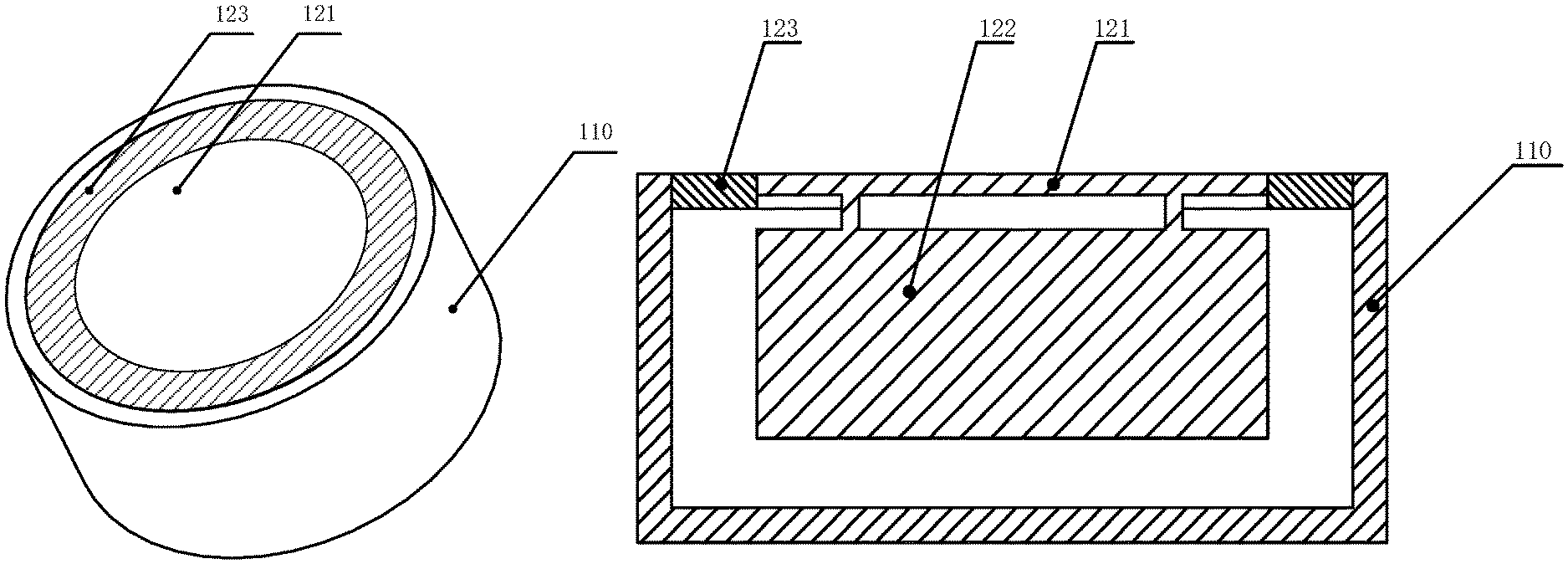
An exemplary structure of a bone conduction speaker based on the principle of the bone conduction speaker is shown in FIGS. 1A and 1B. The bone conduction speaker may include an open housing 110, a vibration board 121, a transducer 122, and a linking component 123. The transducer 122 may transduce electrical signals to mechanical vibrations. The vibration board 121 may be connected to the transducer 122 and vibrate synchronically with the transducer 122. The vibration board 121 may stretch out from the opening of the housing 110 and contact with human skin to pass vibrations to auditory nerves through human tissues and bones, which in turn enables people to hear sound. The linking component 123 may reside between the transducer 122 and the housing 110, configured to fix the vibrating transducer 122 inside the housing 110. To minimize its effect on the vibrations generated by the transducer 122, the linking component 123 may be made of an elastic material.
However, the mechanical vibrations generated by the transducer 122 may not only cause the vibration board 121 to vibrate, but may also cause the housing 110 to vibrate through the linking component 123. Accordingly, the mechanical vibrations generated by the bone conduction speaker may push human tissues through the bone board 121, and at the same time a portion of the vibrating board 121 and the housing 110 that are not in contact with human issues may nevertheless push air. Air sound may thus be generated by the air pushed by the portion of the vibrating board 121 and the housing 110. The air sound may be called "sound leakage." In some cases, sound leakage is harmless. However, sound leakage should be avoided as much as possible if people intend to protect privacy when using the bone conduction speaker or try not to disturb others when listening to music.
Attempting to solve the problem of sound leakage, Korean patent KR10-2009-0082999 discloses a bone conduction speaker of a dual magnetic structure and double-frame. As shown in FIG. 2, the speaker disclosed in the patent includes: a first frame 210 with an open upper portion and a second frame 220 that surrounds the outside of the first frame 210. The second frame 220 is separately placed from the outside of the first frame 210. The first frame 210 includes a movable coil 230 with electric signals, an inner magnetic component 240, an outer magnetic component 250, a magnet field formed between the inner magnetic component 240, and the outer magnetic component 250. The inner magnetic component 240 and the out magnetic component 250 may vibrate by the attraction and repulsion force of the coil 230 placed in the magnet field. A vibration board 260 connected to the moving coil 230 may receive the vibration of the moving coil 230. A vibration unit 270 connected to the vibration board 260 may pass the vibration to a user by contacting with the skin. As described in the patent, the second frame 220 surrounds the first frame 210, in order to use the second frame 220 to prevent the vibration of the first frame 210 from dissipating the vibration to outsides, and thus may reduce sound leakage to some extent.
However, in this design, since the second frame 220 is fixed to the first frame 210, vibrations of the second frame 220 are inevitable. As a result, sealing by the second frame 220 is unsatisfactory. Furthermore, the second frame 220 increases the whole volume and weight of the speaker, which in turn increases the cost, complicates the assembly process, and reduces the speaker's reliability and consistency.
SUMMARY
The embodiments of the present application discloses methods and system of reducing sound leakage of a bone conduction speaker.
In one aspect, the embodiments of the present application disclose a method of reducing sound leakage of a bone conduction speaker, including:
providing a bone conduction speaker including a vibration board fitting human skin and passing vibrations, a transducer, and a housing, wherein at least one sound guiding hole is located in at least one portion of the housing;
the transducer drives the vibration board to vibrate;
the housing vibrates, along with the vibrations of the transducer, and pushes air, forming a leaked sound wave transmitted in the air;
the air inside the housing is pushed out of the housing through the at least one sound guiding hole, interferes with the leaked sound wave, and reduces an amplitude of the leaked sound wave.
In some embodiments, one or more sound guiding holes may locate in an upper portion, a central portion, and/or a lower portion of a sidewall and/or the bottom of the housing.
In some embodiments, a damping layer may be applied in the at least one sound guiding hole in order to adjust the phase and amplitude of the guided sound wave through the at least one sound guiding hole.
In some embodiments, sound guiding holes may be configured to generate guided sound waves having a same phase that reduce the leaked sound wave having a same wavelength; sound guiding holes may be configured to generate guided sound waves having different phases that reduce the leaked sound waves having different wavelengths.
In some embodiments, different portions of a same sound guiding hole may be configured to generate guided sound waves having a same phase that reduce the leaked sound wave having same wavelength. In some embodiments, different portions of a same sound guiding hole may be configured to generate guided sound waves having different phases that reduce leaked sound waves having different wavelengths.
In another aspect, the embodiments of the present application disclose a bone conduction speaker, including a housing, a vibration board and a transducer, wherein:
the transducer is configured to generate vibrations and is located inside the housing;
the vibration board is configured to be in contact with skin and pass vibrations;
At least one sound guiding hole may locate in at least one portion on the housing, and preferably, the at least one sound guiding hole may be configured to guide a sound wave inside the housing, resulted from vibrations of the air inside the housing, to the outside of the housing, the guided sound wave interfering with the leaked sound wave and reducing the amplitude thereof.
In some embodiments, the at least one sound guiding hole may locate in the sidewall and/or bottom of the housing.
In some embodiments, preferably, the at least one sound guiding sound hole may locate in the upper portion and/or lower portion of the sidewall of the housing.
In some embodiments, preferably, the sidewall of the housing is cylindrical and there are at least two sound guiding holes located in the sidewall of the housing, which are arranged evenly or unevenly in one or more circles. Alternatively, the housing may have a different shape.
In some embodiments, preferably, the sound guiding holes have different heights along the axial direction of the cylindrical sidewall.
In some embodiments, preferably, there are at least two sound guiding holes located in the bottom of the housing. In some embodiments, the sound guiding holes are distributed evenly or unevenly in one or more circles around the center of the bottom. Alternatively or additionally, one sound guiding hole is located at the center of the bottom of the housing.
In some embodiments, preferably, the sound guiding hole is a perforative hole. In some embodiments, there may be a damping layer at the opening of the sound guiding hole.
In some embodiments, preferably, the guided sound waves through different sound guiding holes and/or different portions of a same sound guiding hole have different phases or a same phase.
In some embodiments, preferably, the damping layer is a tuning paper, a tuning cotton, a nonwoven fabric, a silk, a cotton, a sponge, or a rubber.
In some embodiments, preferably, the shape of a sound guiding hole is circle, ellipse, quadrangle, rectangle, or linear. In some embodiments, the sound guiding holes may have a same shape or different shapes.
In some embodiments, preferably, the transducer includes a magnetic component and a voice coil. Alternatively, the transducer includes piezoelectric ceramic.
The design disclosed in this application utilizes the principles of sound interference, by placing sound guiding holes in the housing, to guide sound wave(s) inside the housing to the outside of the housing, the guided sound wave(s) interfering with the leaked sound wave, which is formed when the housing's vibrations push the air outside the housing. The guided sound wave(s) reduces the amplitude of the leaked sound wave and thus reduces the sound leakage. The design not only reduces sound leakage, but is also easy to implement, doesn't increase the volume or weight of the bone conduction speaker, and barely increase the cost of the product.
BRIEF DESCRIPTION OF THE DRAWINGS
FIGS. 1A and 1B are schematic structures illustrating a bone conduction speaker of prior art;
FIG. 2 is a schematic structure illustrating another bone conduction speaker of prior art;
FIG. 3 illustrates the principle of sound interference according to some embodiments of the present disclosure;
FIGS. 4A and 4B are schematic structures of an exemplary bone conduction speaker according to some embodiments of the present disclosure;
FIG. 4C is a schematic structure of the bone conduction speaker according to some embodiments of the present disclosure;
FIG. 4D is a diagram illustrating reduced sound leakage of the bone conduction speaker according to some embodiments of the present disclosure;
FIG. 5 is a diagram illustrating the equal-loudness contour curves according to some embodiments of the present disclosure;
FIG. 6 is a flow chart of an exemplary method of reducing sound leakage of a bone conduction speaker according to some embodiments of the present disclosure;
FIGS. 7A and 7B are schematic structures of an exemplary bone conduction speaker according to some embodiments of the present disclosure;
FIG. 7C is a diagram illustrating reduced sound leakage of a bone conduction speaker according to some embodiments of the present disclosure;
FIGS. 8A and 8B are schematic structure of an exemplary bone conduction speaker according to some embodiments of the present disclosure;
FIG. 8C is a diagram illustrating reduced sound leakage of a bone conduction speaker according to some embodiments of the present disclosure;
FIGS. 9A and 9B are schematic structures of an exemplary bone conduction speaker according to some embodiments of the present disclosure;
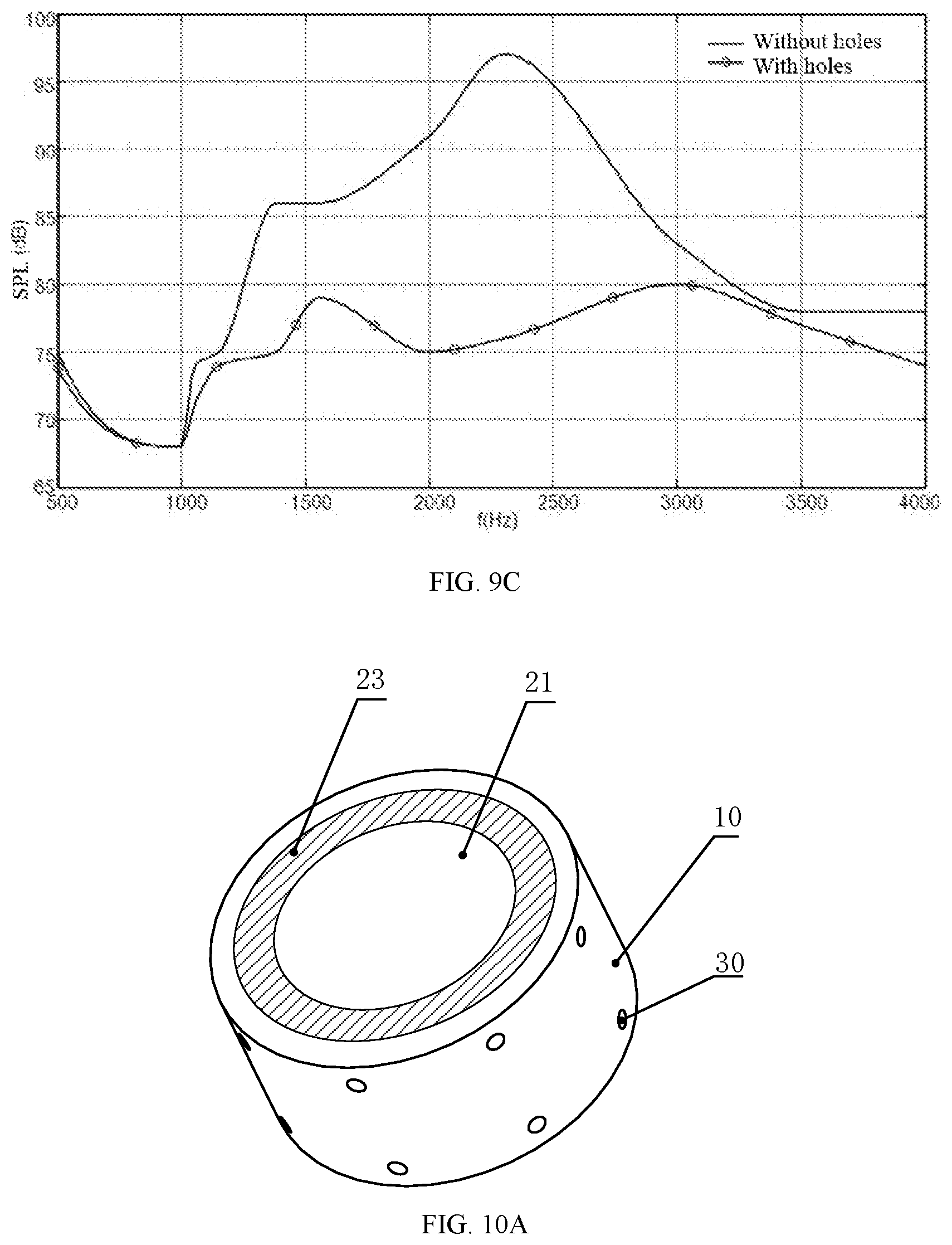
FIG. 9C is a diagram illustrating reduced sound leakage of a bone conduction speaker according to some embodiments of the present disclosure;
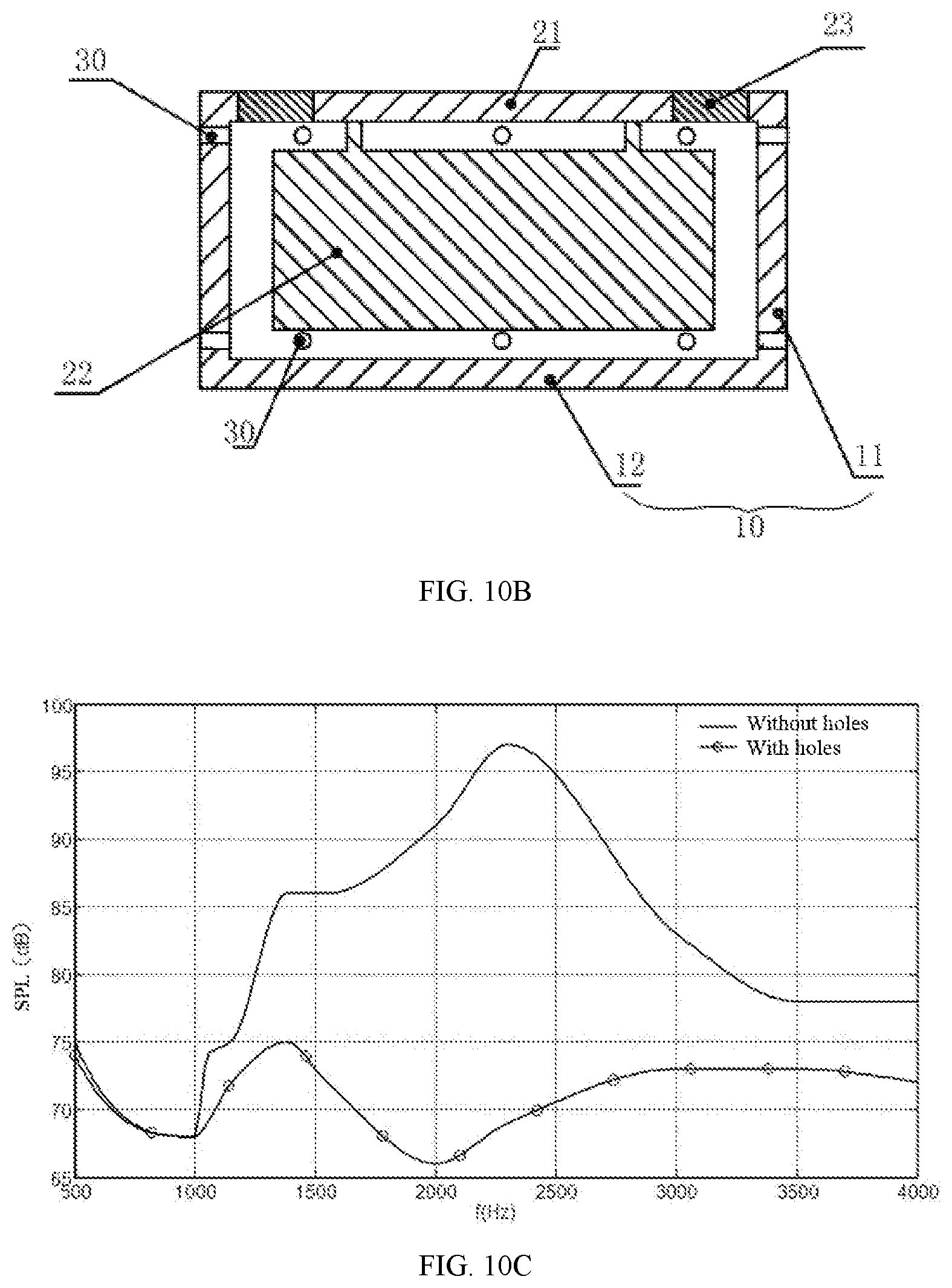
FIGS. 10A and 10B are schematic structures of an exemplary bone conduction speaker according to some embodiments of the present disclosure;
FIG. 10C is a diagram illustrating reduced sound leakage of a bone conduction speaker according to some embodiments of the present disclosure;
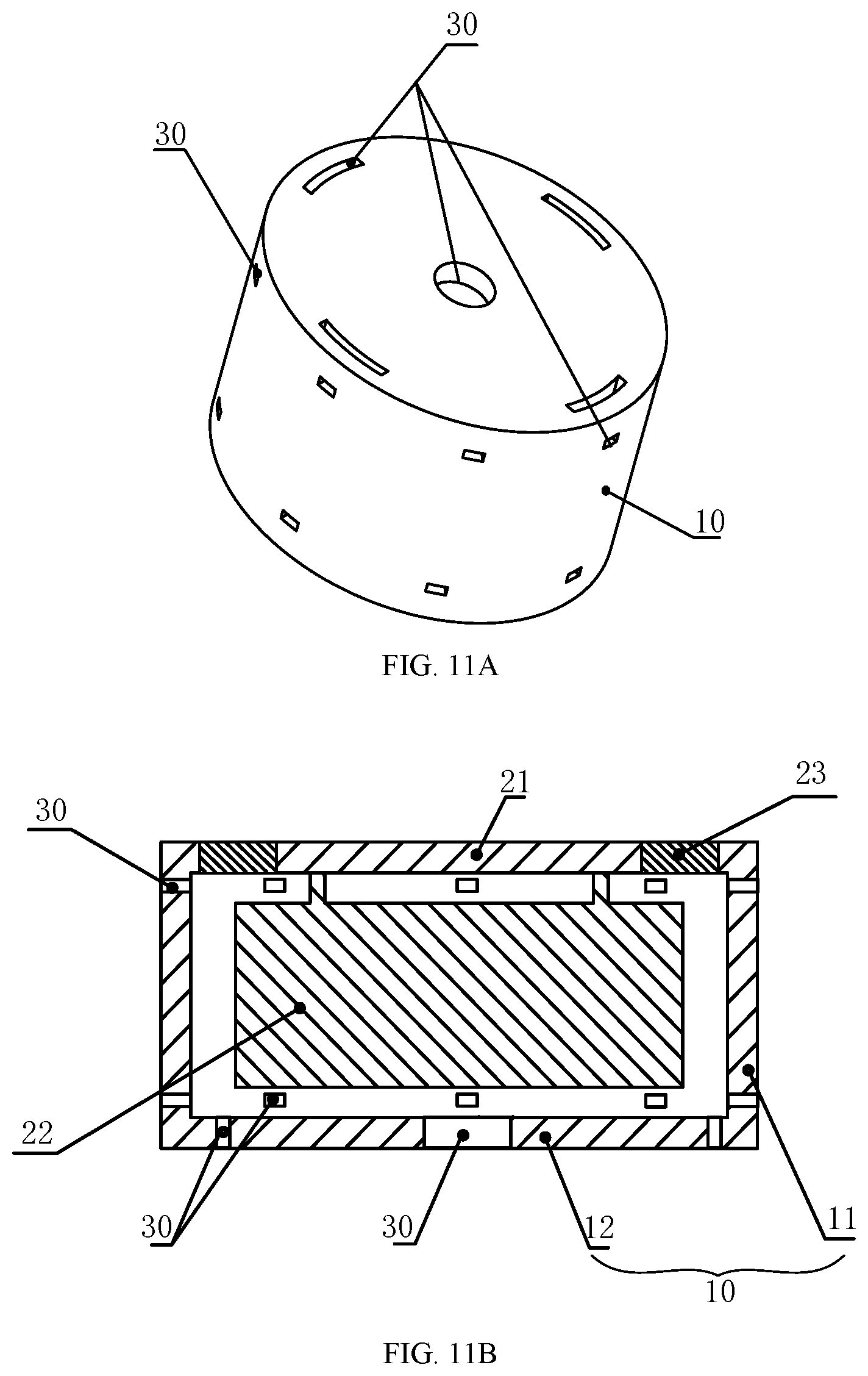
FIGS. 11A and 11B are schematic structures of an exemplary bone conduction speaker according to some embodiments of the present disclosure;
FIG. 11C is a diagram illustrating reduced sound leakage of a bone conduction speaker according to some embodiments of the present disclosure; and
FIGS. 12A and 12B are schematic structures of an exemplary bone conduction speaker according to some embodiments of the present disclosure;
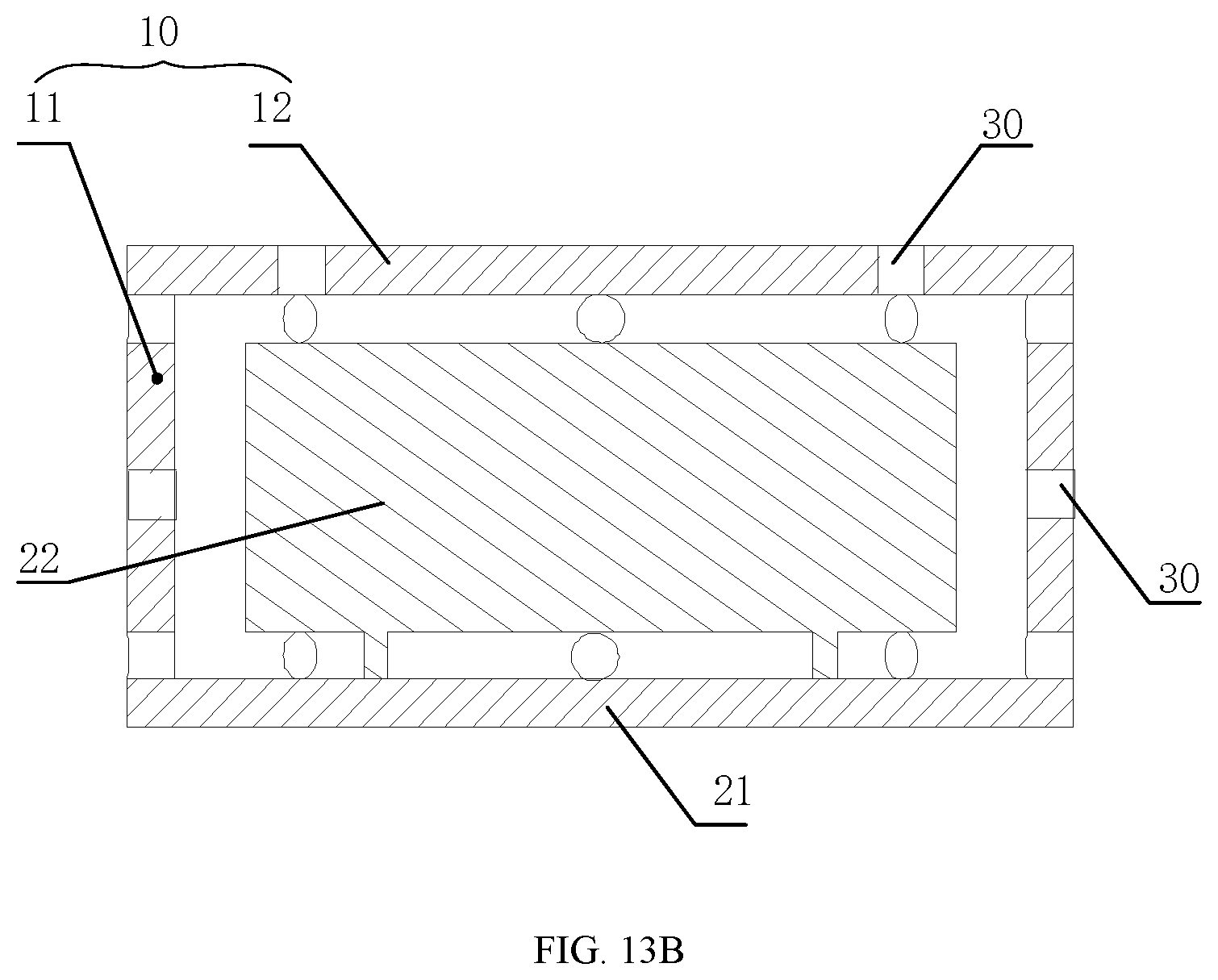
FIGS. 13A and 13B are schematic structures of an exemplary bone conduction speaker according to some embodiments of the present disclosure.
The meanings of the mark numbers in the figures are as followed:
110, open housing; 121, vibration board; 122, transducer; 123, linking component; 210, first frame; 220, second frame; 230, moving coil; 240, inner magnetic component; 250, outer magnetic component; 260; vibration board; 270, vibration unit; 10, housing; 11, sidewall; 12, bottom; 21, vibration board; 22, transducer; 23, linking component; 24, elastic component; 30, sound guiding hole.
DETAILED DESCRIPTION
Followings are some further detailed illustrations about this disclosure. The following examples are for illustrative purposes only and should not be interpreted as limitations of the claimed invention. There are a variety of alternative techniques and procedures available to those of ordinary skill in the art, which would similarly permit one to successfully perform the intended invention. In addition, the figures just show the structures relative to this disclosure, not the whole structure.
To explain the scheme of the embodiments of this disclosure, the design principles of this disclosure will be introduced here. FIG. 3 illustrates the principles of sound interference according to some embodiments of the present disclosure. Two or more sound waves may interfere in the space based on, for example, the frequency and/or amplitude of the waves. Specifically, the amplitudes of the sound waves with the same frequency may be overlaid to generate a strengthened wave or a weakened wave. As shown in FIG. 3, sound source 1 and sound source 2 have the same frequency and locate in different locations in the space. The sound waves generated from these two sound sources may encounter in an arbitrary point A. If the phases of the sound wave 1 and sound wave 2 are the same at point A, the amplitudes of the two sound waves may be added, generating a strengthened sound wave signal at point A; on the other hand, if the phases of the two sound waves are opposite at point A, their amplitudes may be offset, generating a weakened sound wave signal at point A.
This disclosure applies above-noted the principles of sound wave interference to a bone conduction speaker and disclose a bone conduction speaker that can reduce sound leakage.
Embodiment One
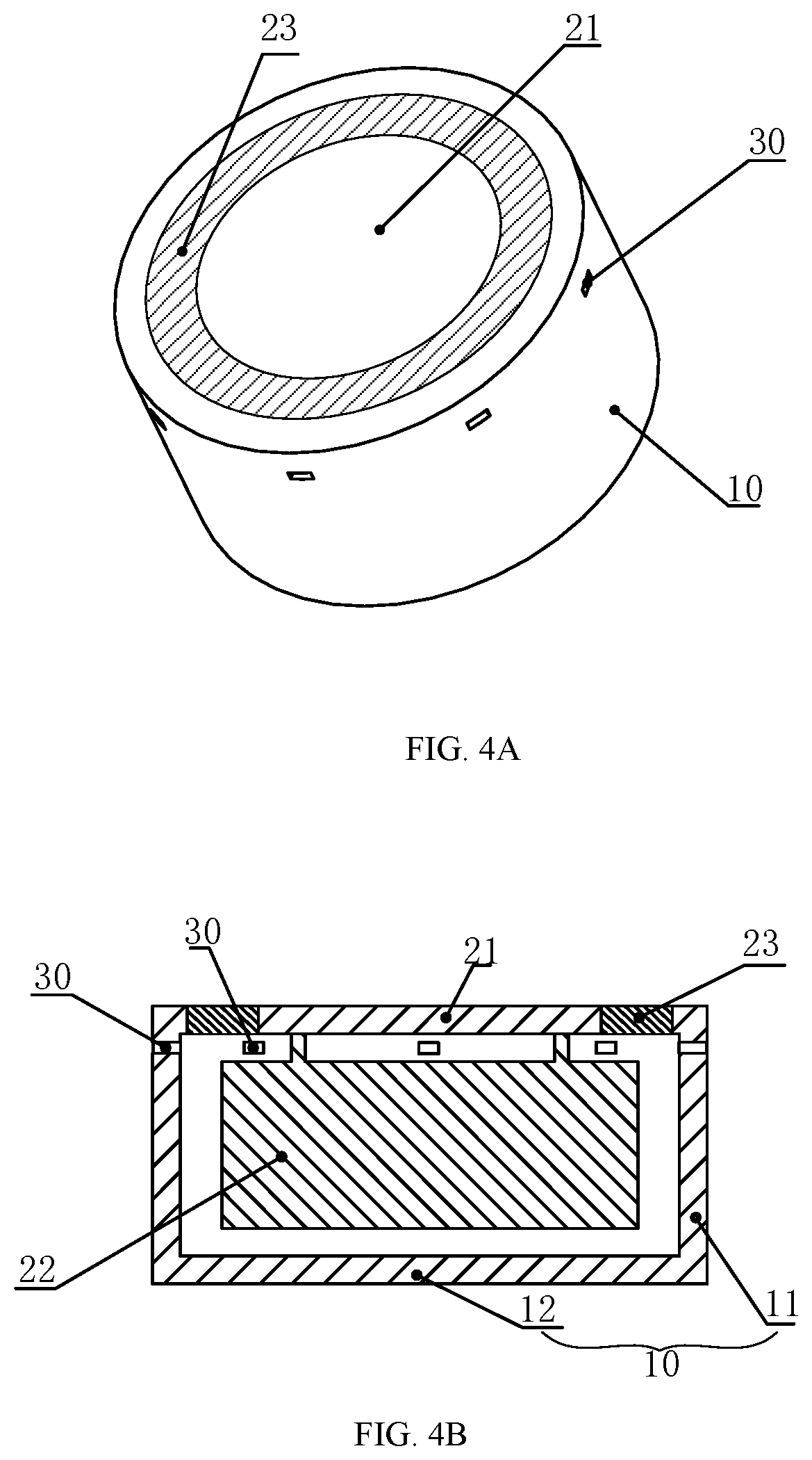
FIGS. 4A and 4B are schematic structures of an exemplary bone conduction speaker. The bone conduction speaker may include a housing 10, a vibration board 21, and a transducer 22. The transducer 22 may be inside the housing 10 and configured to generate vibrations. The housing 10 may have one or more sound guiding holes 30. The sound guiding hole(s) 30 may be configured to guide sound waves inside the housing 10 to the outside of the housing 10. In some embodiments, the guided sound waves may form interference with leaked sound waves generated by the vibrations of the housing 10, so as to reducing the amplitude of the leaked sound. The transducer 22 may be configured to convert an electrical signal to mechanical vibrations. For example, an audio electrical signal may be transmitted into a voice coil that is placed in a magnet, and the electromagnetic interaction may cause the voice coil to vibrate based on the audio electrical signal. As another example, the transducer 22 may include piezoelectric ceramics, shape changes of which may cause vibrations in accordance with electrical signals received.
Furthermore, the vibration board 21 may be connected to the transducer 22 and configured to vibrate along with the transducer 22. The vibration board 21 may stretch out from the opening of the housing 10, and touch the skin of the user and pass vibrations to auditory nerves through human tissues and bones, which in turn enables the user to hear sound. The linking component 23 may reside between the transducer 22 and the housing 10, configured to fix the vibrating transducer 122 inside the housing. The linking component 23 may include one or more separate components, or may be integrated with the transducer 22 or the housing 10. In some embodiments, the linking component 23 is made of an elastic material.
The transducer 22 may drive the vibration board 21 to vibrate. The transducer 22, which resides inside the housing 10, may vibrate. The vibrations of the transducer 22 may drives the air inside the housing 10 to vibrate, producing a sound wave inside the housing 10, which can be referred to as "sound wave inside the housing." Since the vibration board 21 and the transducer 22 are fixed to the housing 10 via the linking component 23, the vibrations may pass to the housing 10, causing the housing 10 to vibrate synchronously. The vibrations of the housing 10 may generate a leaked sound wave, which spreads outwards as sound leakage.
The sound wave inside the housing and the leaked sound wave are like the two sound sources in FIG. 3. In some embodiments, the sidewall 11 of the housing 10 may have one or more sound guiding holes 30 configured to guide the sound wave inside the housing 10 to the outside. The guided sound wave through the sound guiding hole(s) 30 may interfere with the leaked sound wave generated by the vibrations of the housing 10, and the amplitude of the leaked sound wave may be reduced due to the interference, which may result in a reduced sound leakage. Therefore, the design of this embodiment can solve the sound leakage problem to some extent by making an improvement of setting a sound guiding hole on the housing, and not increasing the volume and weight of the bone conduction speaker.
In some embodiments, one sound guiding hole 30 is set on the upper portion of the sidewall 11. As used herein, the upper portion of the sidewall 11 refers to the portion of the sidewall 11 starting from the top of the sidewall (contacting with the vibration board 21) to about the 1/3 height of the sidewall.
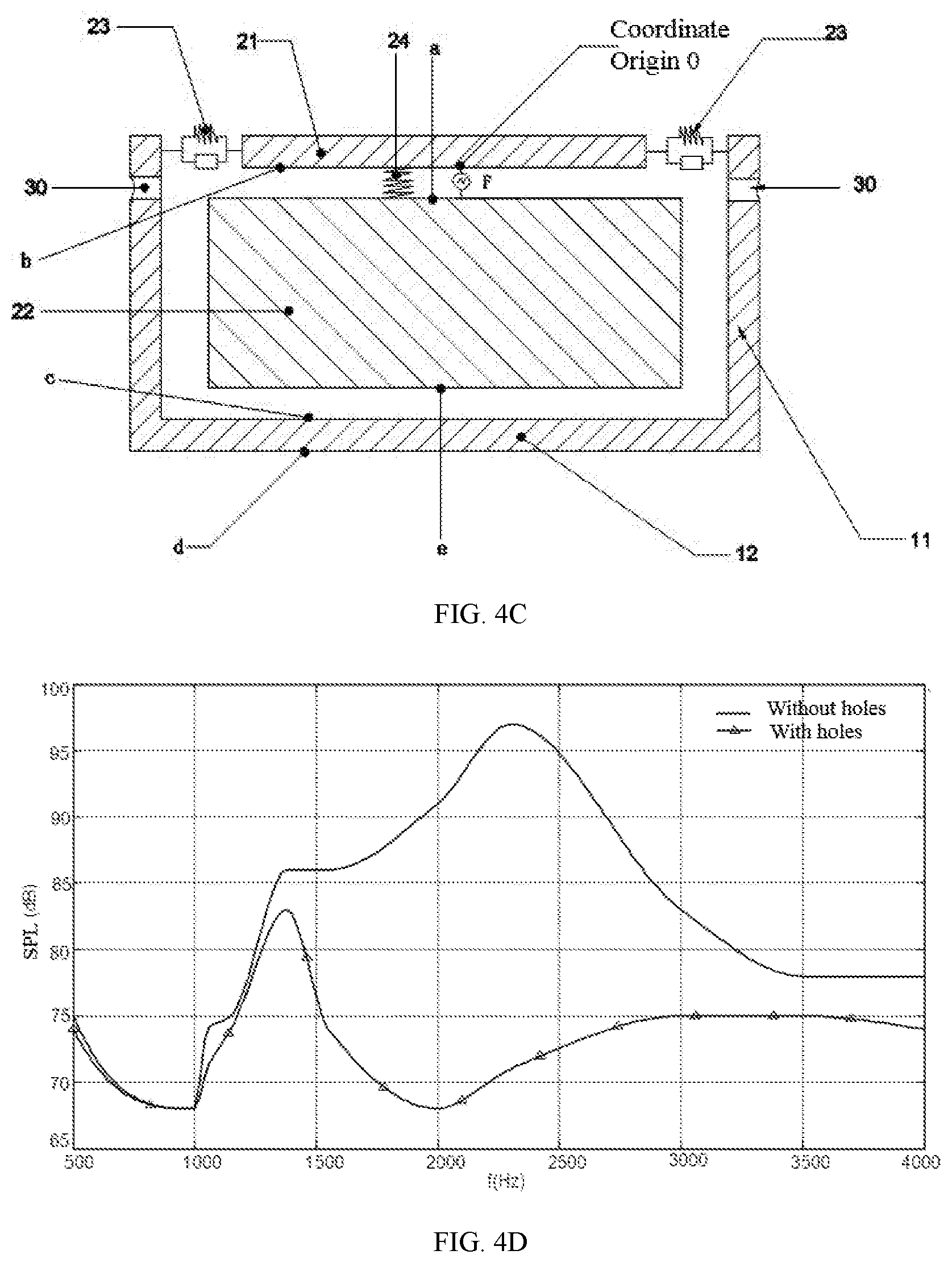
FIG. 4C is a schematic structure of the bone conduction speaker illustrated in FIGS. 4A-4B. The structure of the bone conduction speaker is further illustrated with mechanics elements illustrated in FIG. 4C. As shown in FIG. 4C, the linking component 23 between the sidewall 11 of the housing 10 and the vibration board 21 may be represented by an elastic element 23 and a damping element in the parallel connection. The linking relationship between the vibration board 21 and the transducer 22 may be represented by an elastic element 24.
Outside the housing 10, the sound leakage reduction is proportional to (.intg..intg..sub.S.sub.holePds-.intg..intg..sub.S.sub.housingP.sub.dds) (1)
wherein S.sub.hole is the area of the opening of the sound guiding hole 30, S.sub.housing is the area of the housing 10 (e.g., the sidewall 11 and the bottom 12) that is not in contact with human face.
The pressure inside the housing may be expressed as P=P.sub.a+P.sub.b+P.sub.c+P.sub.e (2)
wherein P.sub.a, P.sub.b, P.sub.c and P.sub.e are the sound pressures of an arbitrary point inside the housing 10 generated by side a, side b, side c and side e (as illustrated in FIG. 4C), respectively. As used herein, side a refers to the upper surface of the transducer 22 that is close to the vibration board 21, side b refers to the lower surface of the vibration board 21 that is close to the transducer 22, side c refers to the inner upper surface of the bottom 12 that is close to the transducer 22, and side e refers to the lower surface of the transducer 22 that is close to the bottom 12.
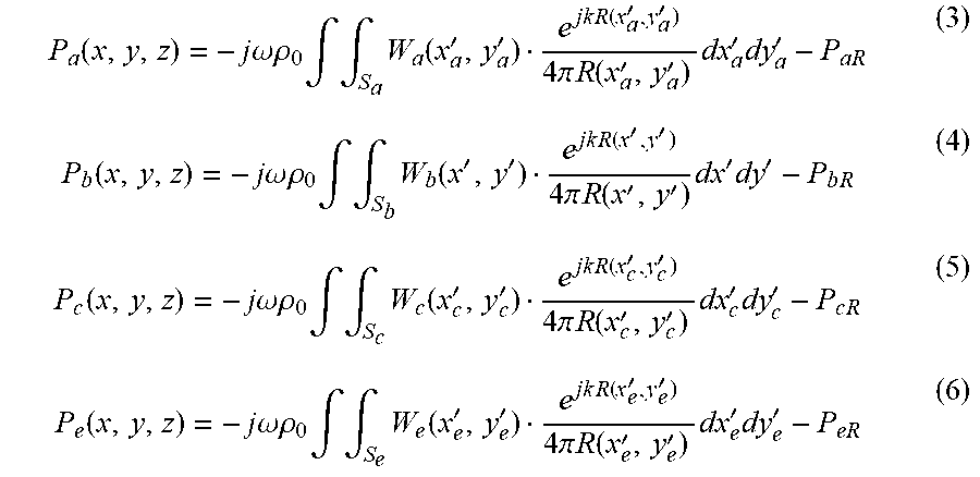
The center of the side b, 0 point, is set as the origin of the space coordinates, and the side b can be set as the z=0 plane, so P.sub.a, P.sub.b, P.sub.c and P.sub.e may be expressed as follows:
.function..times..times..omega..times..times..rho..times..intg..intg..tim- es..function.''.times..times..times..times..function.''.times..times..pi..- times..times..function.''.times..times.'.times.'.times..times..function..t- imes..times..omega..times..times..rho..times..intg..intg..times..function.- ''.times..times..times..times..function.''.times..times..pi..times..times.- .function.''.times.'.times.'.times..times..function..times..times..omega..- times..times..rho..times..intg..intg..times..function.''.times..times..tim- es..times..function.''.times..times..pi..times..times..function.''.times..- times.'.times.'.times..times..function..times..times..omega..times..times.- .rho..times..intg..intg..times..function.''.times..times..times..times..fu- nction.''.times..times..pi..times..times..function.''.times..times.'.times- .' ##EQU00001## wherein R(x', y')= {square root over ((x-x').sup.2+(y-y').sup.2+z.sup.2)} is the distance between an observation point (x, y, z) and a point on side b (x', y', 0); S.sub.a, S.sub.b, S.sub.c and S.sub.e are the areas of side a, side b, side c and side e, respectively; R(x'.sub.a, y'.sub.a)= {square root over ((x-x.sub.a').sup.2+(y-y.sub.a').sup.2+(z-z.sub.a).sup.2)} is the distance between the observation point (x, y, z) and a point on side a (x'.sub.a, y'.sub.a, z.sub.a); R(x'.sub.c, y'.sub.c)= {square root over ((x-x.sub.c').sup.2+(y-y.sub.c').sup.2+(z-z.sub.c).sup.2)} is the distance between the observation point (x, y, z) and a point on side c (x'.sub.c, y'.sub.c, z.sub.c); R(x'.sub.e, y'.sub.e)= {square root over ((x-x.sub.e').sup.2+(y-y.sub.e').sup.2+(z-z.sub.e).sup.2)} is the distance between the observation point (x, y, z) and a point on side e (x'.sub.e, y'.sub.e, z.sub.e); k=.omega./u(u is the velocity of sound) is wave number, .rho..sub.0 is an air density, .omega. is an angular frequency of vibration;
P.sub.aR, P.sub.bR, P.sub.cR and P.sub.eR are acoustic resistances of air, which respectively are:
.times..times..times..times..omega.'.phi..delta..times..times..times..tim- es..omega.'.phi..delta..times..times..times..times..omega.'.phi..delta..ti- mes..times..omega.'.phi..delta. ##EQU00002## wherein r is the acoustic resistance per unit length, r' is the sound quality per unit length, z.sub.a is the distance between the observation point and side a, z.sub.b is the distance between the observation point and side b, z.sub.c is the distance between the observation point and side c, z.sub.e is the distance between the observation point and side e.
W.sub.a(x, y), W.sub.b(x, y), W.sub.c(x, y), W.sub.e(x, y) and W.sub.d(x, y) are the sound source power per unit area of side a, side b, side c, side e and side d, respectively, which can be derived from following formulas (11): F.sub.e=F.sub.a=F-k.sub.1 cos .omega.t-.intg..intg..sub.S.sub.aW.sub.a(x,y)dxdy-.intg..intg..sub.S.sub.- eW.sub.e(x,y)dxdy-f F.sub.b=-F+k.sub.1 cos .omega.t+.intg..intg..sub.S.sub.bW.sub.b(x,y)dxdy-.intg..intg..sub.S.sub.- eW.sub.e(x,y)dxdy-L F.sub.c=F.sub.d=F.sub.b-k.sub.2 cos .omega.t-.intg..intg..sub.S.sub.cW.sub.c(x,y)dxdy-f-.gamma. F.sub.d=F.sub.b-k.sub.2 cos .omega.t-.intg..intg..sub.S.sub.dW.sub.d(x,y)dxdy (11) wherein F is the driving force generated by the transducer 22, F.sub.a, F.sub.b, F.sub.c, F.sub.d, and F.sub.e are the driving forces of side a, side b, side c, side d and side e, respectively. As used herein, side d is the outside surface of the bottom 12. S.sub.d is the region of side d, f is the viscous resistance formed in the small gap of the sidewalls, and f=.eta..DELTA.s(dv/dy).
L is the equivalent load on human face when the vibration board acts on the human face, .gamma. is the energy dissipated on elastic element 24, k.sub.1 and k.sub.2 are the elastic coefficients of elastic element 23 and elastic element 24 respectively, .eta. is the fluid viscosity coefficient, dv/dy is the velocity gradient of fluid, .DELTA.s is the cross-section area of a subject (board), A is the amplitude, .phi. is the region of the sound field, and .delta. is a high order minimum (which is generated by the incompletely symmetrical shape of the housing);
The sound pressure of an arbitrary point outside the housing, generated by the vibration of the housing 10 is expressed as:
.times..times..omega..times..times..rho..times..intg..intg..function.''.t- imes..times..times..times..function.''.times..times..pi..times..times..fun- ction.''.times..times.'.times.' ##EQU00003## wherein R(x'.sub.d, y'.sub.d)= {square root over ((x-x.sub.d').sup.2+(y-y.sub.d').sup.2+(z-z.sub.d).sup.2)} is the distance between the observation point (x, y, z) and a point on side d (x'.sub.d, y'.sub.d, z.sub.d).
P.sub.a, P.sub.b, P.sub.c and P.sub.e are functions of the position, when we set a hole on an arbitrary position in the housing, if the area of the hole is S.sub.hole, the sound pressure of the hole is .intg..intg..sub.S.sub.hole Pds.
In the meanwhile, because the vibration board 21 fits human tissues tightly, the power it gives out is absorbed all by human tissues, so the only side that can push air outside the housing to vibrate is side d, thus forming sound leakage. As described elsewhere, the sound leakage is resulted from the vibrations of the housing 10. For illustrative purposes, the sound pressure generated by the housing 10 may be expressed as .intg..intg..sub.S.sub.housing P.sub.dds.
The leaked sound wave and the guided sound wave interference may result in a weakened sound wave, i.e., to make .intg..intg..sub.S.sub.hole Pds and .intg..intg..sub.S.sub.housing P.sub.dds have the same value but opposite directions, and the sound leakage may be reduced. In some embodiments, .intg..intg..sub.S.sub.hole Pds may be adjusted to reduce the sound leakage. Since .intg..intg..sub.S.sub.hole Pds corresponds to information of phases and amplitudes of one or more holes, which further relates to dimensions of the housing of the bone conduction speaker, the vibration frequency of the transducer, the position, shape, quantity and/or size of the sound guiding holes and whether there is damping inside the holes. Thus, the position, shape, and quantity of sound guiding holes, and/or damping materials may be adjusted to reduce sound leakage.
Additionally, because of the basic structure and function differences of a bone conduction speaker and a traditional air conduction speaker, the formulas above are only suitable for bone conduction speakers. Whereas in traditional air conduction speakers, the air in the air housing can be treated as a whole, which is not sensitive to positions, and this is different intrinsically with a bone conduction speaker, therefore the above formulas are not suitable to an air conduction speaker.
According to the formulas above, a person having ordinary skill in the art would understand that the effectiveness of reducing sound leakage is related to the dimensions of the housing of the bone conduction speaker, the vibration frequency of the transducer, the position, shape, quantity and size of the sound guiding hole(s) and whether there is damping inside the sound guiding hole(s). Accordingly, various configurations, depending on specific needs, may be obtained by choosing specific position where the sound guiding hole(s) is located, the shape and/or quantity of the sound guiding hole(s) as well as the damping material.
FIG. 5 is a diagram illustrating the equal-loudness contour curves according to some embodiments of the present disclose. The horizontal coordinate is frequency, while the vertical coordinate is sound pressure level (SPL). As used herein, the SPL refers to the change of atmospheric pressure after being disturbed, i.e., a surplus pressure of the atmospheric pressure, which is equivalent to an atmospheric pressure added to a pressure change caused by the disturbance. As a result, the sound pressure may reflect the amplitude of a sound wave. In FIG. 5, on each curve, sound pressure levels corresponding to different frequencies are different, while the loudness levels felt by human ears are the same. For example, each curve is labeled with a number representing the loudness level of said curve. According to the loudness level curves, when volume (sound pressure amplitude) is lower, human ears are not sensitive to sounds of high or low frequencies; when volume is higher, human ears are more sensitive to sounds of high or low frequencies. Bone conduction speakers may generate sound relating to different frequency ranges, such as 1000 Hz.about.4000 Hz, or 1000 Hz.about.4000 Hz, or 1000 Hz.about.3500 Hz, or 1000 Hz.about.3000 Hz, or 1500 Hz.about.3000 Hz. The sound leakage within the above-mentioned frequency ranges may be the sound leakage aimed to be reduced with a priority.
FIG. 4D is a diagram illustrating the effect of reduced sound leakage according to some embodiments of the present disclosure, wherein the test results and calculation results are close in the above range. The bone conduction speaker being tested includes a cylindrical housing, which includes a sidewall and a bottom, as described in FIGS. 4A and 4B. The cylindrical housing is in a cylinder shape having a radius of 22 mm, the sidewall height of 14 mm, and a plurality of sound guiding holes being set on the upper portion of the sidewall of the housing. The openings of the sound guiding holes are rectangle. The sound guiding holes are arranged evenly on the sidewall. The target region where the sound leakage is to be reduced is 50 cm away from the outside of the bottom of the housing. The distance of the leaked sound wave spreading to the target region and the distance of the sound wave spreading from the surface of the transducer 20 through the sound guiding holes 20 to the target region have a difference of about 180 degrees in phase. As shown, the leaked sound wave is reduced in the target region dramatically or even be eliminated.
According to the embodiments in this disclosure, the effectiveness of reducing sound leakage after setting sound guiding holes is very obvious. As shown in FIG. 4D, the bone conduction speaker having sound guiding holes greatly reduce the sound leakage compared to the bone conduction speaker without sound guiding holes.
In the tested frequency range, after setting sound guiding holes, the sound leakage is reduced by about 10 dB on average. Specifically, in the frequency range of 1500 Hz.about.3000 Hz, the sound leakage is reduced by over 10 dB. In the frequency range of 2000 Hz.about.2500 Hz, the sound leakage is reduced by over 20 dB compared to the scheme without sound guiding holes.
A person having ordinary skill in the art can understand from the above-mentioned formulas that when the dimensions of the bone conduction speaker, target regions to reduce sound leakage and frequencies of sound waves differ, the position, shape and quantity of sound guiding holes also need to adjust accordingly.
For example, in a cylinder housing, according to different needs, a plurality of sound guiding holes may be on the sidewall and/or the bottom of the housing. Preferably, the sound guiding hole may be set on the upper portion and/or lower portion of the sidewall of the housing. The quantity of the sound guiding holes set on the sidewall of the housing is no less than two. Preferably, the sound guiding holes may be arranged evenly or unevenly in one or more circles with respect to the center of the bottom. In some embodiments, the sound guiding holes may be arranged in at least one circle. In some embodiments, one sound guiding hole may be set on the bottom of the housing. In some embodiments, the sound guiding hole may be set at the center of the bottom of the housing.
The quantity of the sound guiding holes can be one or more. Preferably, multiple sound guiding holes may be set symmetrically on the housing. In some embodiments, there are 6-8 circularly arranged sound guiding holes.
The openings (and cross sections) of sound guiding holes may be circle, ellipse, rectangle, or slit. Slit generally means slit along with straight lines, curve lines, or arc lines. Different sound guiding holes in one bone conduction speaker may have same or different shapes.
A person having ordinary skill in the art can understand that, the sidewall of the housing may not be cylindrical, the sound guiding holes can be arranged asymmetrically as needed. Various configurations may be obtained by setting different combinations of the shape, quantity, and position of the sound guiding. Some other embodiments along with the figures are described as follows.
Embodiment Two
FIG. 6 is a flowchart of an exemplary method of reducing sound leakage of a bone conduction speaker according to some embodiments of the present disclosure. At 601, a bone conduction speaker including a vibration plate 21 touching human skin and passing vibrations, a transducer 22, and a housing 10 is provided. At least one sound guiding hole 30 is arranged on the housing 10. At 602, the vibration plate 21 is driven by the transducer 22, causing the vibration 21 to vibrate. At 603, a leaked sound wave due to the vibrations of the housing is formed, wherein the leaked sound wave transmits in the air. At 604, a guided sound wave passing through the at least one sound guiding hole 30 from the inside to the outside of the housing 10. The guided sound wave interferes with the leaked sound wave, reducing the sound leakage of the bone conduction speaker.
The sound guiding holes 30 are preferably set at different positions of the housing 10.
The effectiveness of reducing sound leakage may be determined by the formulas and method as described above, based on which the positions of sound guiding holes may be determined.
A damping layer is preferably set in a sound guiding hole 30 to adjust the phase and amplitude of the sound wave transmitted through the sound guiding hole 30.
In some embodiments, different sound guiding holes may generate different sound waves having a same phase to reduce the leaked sound wave having the same wavelength. In some embodiments, different sound guiding holes may generate different sound waves having different phases to reduce the leaked sound waves having different wavelengths.
In some embodiments, different portions of a sound guiding hole 30 may be configured to generate sound waves having a same phase to reduce the leaked sound waves with the same wavelength. In some embodiments, different portions of a sound guiding hole 30 may be configured to generate sound waves having different phases to reduce the leaked sound waves with different wavelengths.
Additionally, the sound wave inside the housing may be processed to basically have the same value but opposite phases with the leaked sound wave, so that the sound leakage may be further reduced.
Embodiment Three
FIGS. 7A and 7B are schematic structures illustrating an exemplary bone conduction speaker according to some embodiments of the present disclosure. The bone conduction speaker may include an open housing 10, a vibration board 21, and a transducer 22. The housing 10 may cylindrical and have a sidewall and a bottom. A plurality of sound guiding holes 30 may be arranged on the lower portion of the sidewall (i.e., from about the 2/3 height of the sidewall to the bottom). The quantity of the sound guiding holes 30 may be 8, the openings of the sound guiding holes 30 may be rectangle. The sound guiding holes 30 may be arranged evenly or evenly in one or more circles on the sidewall of the housing 10.
In the embodiment, the transducer 22 is preferably implemented based on the principle of electromagnetic transduction. The transducer may include components such as magnetizer, voice coil, and etc., and the components may located inside the housing and may generate synchronous vibrations with a same frequency.
FIG. 7C is a diagram illustrating reduced sound leakage according to some embodiments of the present disclosure. In the frequency range of 1400 Hz.about.4000 Hz, the sound leakage is reduced by more than 5 dB, and in the frequency range of 2250 Hz.about.2500 Hz, the sound leakage is reduced by more than 20 dB.
Embodiment Four
FIGS. 8A and 8B are schematic structures illustrating an exemplary bone conduction speaker according to some embodiments of the present disclosure. The bone conduction speaker may include an open housing 10, a vibration board 21, and a transducer 22. The housing 10 is cylindrical and have a sidewall and a bottom. The sound guiding holes 30 may be arranged on the central portion of the sidewall of the housing (i.e., from about the 1/3 height of the sidewall to the 2/3 height of the sidewall). The quantity of the sound guiding holes 30 may be 8, and the openings (and cross sections) of the sound guiding hole 30 may be rectangle. The sound guiding holes 30 may be arranged evenly or unevenly in one or more circles on the sidewall of the housing 10.
In the embodiment, the transducer 21 may be implemented preferably based on the principle of electromagnetic transduction. The transducer 21 may include components such as magnetizer, voice coil, etc., which may be placed inside the housing and may generate synchronous vibrations with the same frequency.
FIG. 8C is a diagram illustrating reduced sound leakage. In the frequency range of 1000 Hz.about.4000 Hz, the effectiveness of reducing sound leakage is great. For example, in the frequency range of 1400 Hz.about.2900 Hz, the sound leakage is reduced by more than 10 dB; in the frequency range of 2200 Hz.about.2500 Hz, the sound leakage is reduced by more than 20 dB.
It's illustrated that the effectiveness of reduced sound leakage can be adjusted by changing the positions of the sound guiding holes, while keeping other parameters relating to the sound guiding holes unchanged.
Embodiment Five
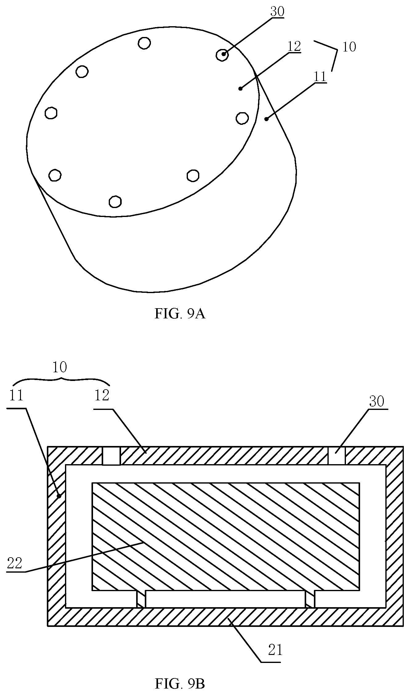
FIGS. 9A and 9B are schematic structures of an exemplary bone conduction speaker according to some embodiments of the present disclosure. The bone conduction speaker may include an open housing 10, a vibration board 21 and a transducer 22. The housing 10 is cylindrical, with a sidewall and a bottom. One or more perforative sound guiding holes 30 may be along the circumference of the bottom. In some embodiments, there may be 8 sound guiding holes 30 arranged evenly of unevenly in one or more circles on the bottom of the housing 10. In some embodiments, the shape of one or more of the sound guiding holes 30 may be rectangle.
In the embodiment, the transducer 21 may be implemented preferably based on the principle of electromagnetic transduction. The transducer 21 may include components such as magnetizer, voice coil, etc., which may be placed inside the housing and may generate synchronous vibration with the same frequency.
FIG. 9C is a diagram illustrating the effect of reduced sound leakage. In the frequency range of 1000 Hz.about.3000 Hz, the effectiveness of reducing sound leakage is outstanding. For example, in the frequency range of 1700 Hz.about.2700 Hz, the sound leakage is reduced by more than 10 dB; in the frequency range of 2200 Hz.about.2400 Hz, the sound leakage is reduced by more than 20 dB.
Embodiment Six
FIGS. 10A and 10B are schematic structures of an exemplary bone conduction speaker according to some embodiments of the present disclosure. The bone conduction speaker may include an open housing 10, a vibration board 21 and a transducer 22. One or more perforative sound guiding holes 30 may be arranged on both upper and lower portions of the sidewall of the housing 10. The sound guiding holes 30 may be arranged evenly or unevenly in one or more circles on the upper and lower portions of the sidewall of the housing 10. In some embodiments, the quantity of sound guiding holes 30 in every circle may be 8, and the upper portion sound guiding holes and the lower portion sound guiding holes may be symmetrical about the central cross section of the housing 10. In some embodiments, the shape of the sound guiding hole 30 may be circle.
The shape of the sound guiding holes on the upper portion and the shape of the sound guiding holes on the lower portion may be different; One or more damping layers may be arranged in the sound guiding holes to reduce leaked sound waves of the same wave length (or frequency), or to reduce leaked sound waves of different wave lengths.
FIG. 10C is a diagram illustrating the effect of reducing sound leakage according to some embodiments of the present disclosure. In the frequency range of 1000 Hz.about.4000 Hz, the effectiveness of reducing sound leakage is outstanding. For example, in the frequency range of 1600 Hz.about.2700 Hz, the sound leakage is reduced by more than 15 dB; in the frequency range of 2000 Hz.about.2500 Hz, where the effectiveness of reducing sound leakage is most outstanding, the sound leakage is reduced by more than 20 dB. Compared to embodiment three, this scheme has a relatively balanced effect of reduced sound leakage on various frequency range, and this effect is better than the effect of schemes where the height of the holes are fixed, such as schemes of embodiment three, embodiment four, embodiment five, and so on.
Embodiment Seven
FIGS. 11A and 11B are schematic structures illustrating a bone conduction speaker according to some embodiments of the present disclosure. The bone conduction speaker may include an open housing 10, a vibration board 21 and a transducer 22. One or more perforative sound guiding holes 30 may be set on upper and lower portions of the sidewall of the housing 10 and on the bottom of the housing 10. The sound guiding holes 30 on the sidewall are arranged evenly or unevenly in one or more circles on the upper and lower portions of the sidewall of the housing 10. In some embodiments, the quantity of sound guiding holes 30 in every circle may be 8, and the upper portion sound guiding holes and the lower portion sound guiding holes may be symmetrical about the central cross section of the housing 10. In some embodiments, the shape of the sound guiding hole 30 may be rectangular. There may be four sound guiding holds 30 on the bottom of the housing 10. The four sound guiding holes 30 may be linear-shaped along arcs, and may be arranged evenly or unevenly in one or more circles with respect to the center of the bottom. Furthermore, the sound guiding holes 30 may include a circular perforative hole on the center of the bottom.
FIG. 11C is a diagram illustrating the effect of reducing sound leakage of the embodiment. In the frequency range of 1000 Hz.about.4000 Hz, the effectiveness of reducing sound leakage is outstanding. For example, in the frequency range of 1300 Hz.about.3000 Hz, the sound leakage is reduced by more than 10 dB; in the frequency range of 2000 Hz.about.2700 Hz, the sound leakage is reduced by more than 20 dB. Compared to embodiment three, this scheme has a relatively balanced effect of reduced sound leakage within various frequency range, and this effect is better than the effect of schemes where the height of the holes are fixed, such as schemes of embodiment three, embodiment four, embodiment five, and etc. Compared to embodiment six, in the frequency range of 1000 Hz.about.1700 Hz and 2500 Hz.about.4000 Hz, this scheme has a better effect of reduced sound leakage than embodiment six.
Embodiment Eight
FIGS. 12A and 12B are schematic structures illustrating a bone conduction speaker according to some embodiments of the present disclosure. The bone conduction speaker may include an open housing 10, a vibration board 21 and a transducer 22. A perforative sound guiding hole 30 may be set on the upper portion of the sidewall of the housing 10. One or more sound guiding holes may be arranged evenly or unevenly in one or more circles on the upper portion of the sidewall of the housing 10. There may be 8 sound guiding holes 30, and the shape of the sound guiding holes 30 may be circle.
After comparison of calculation results and test results, the effectiveness of this embodiment is basically the same with that of embodiment one, and this embodiment can effectively reduce sound leakage.
Embodiment Nine
FIGS. 13A and 13B are schematic structures illustrating a bone conduction speaker according to some embodiments of the present disclosure. The bone conduction speaker may include an open housing 10, a vibration board 21 and a transducer 22.
The difference between this embodiment and the above-described embodiment three is that to reduce sound leakage to greater extent, the sound guiding holes 30 may be arranged on the upper, central and lower portions of the sidewall 11. The sound guiding holes 30 are arranged evenly or unevenly in one or more circles. Different circles are formed by the sound guiding holes 30, one of which is set along the circumference of the bottom 12 of the housing 10. The size of the sound guiding holes 30 are the same.
The effect of this scheme may cause a relatively balanced effect of reducing sound leakage in various frequency ranges compared to the schemes where the position of the holes are fixed. The effect of this design on reducing sound leakage is relatively better than that of other designs where the heights of the holes are fixed, such as embodiment three, embodiment four, embodiment five, etc.
Embodiment Ten
The sound guiding holes 30 in the above embodiments may be perforative holes without shields.
In order to adjust the effect of the sound waves guided from the sound guiding holes, a damping layer (not shown in the figures) may locate at the opening of a sound guiding hole 30 to adjust the phase and/or the amplitude of the sound wave.
There are multiple variations of materials and positions of the damping layer. For example, the damping layer may be made of materials which can damp sound waves, such as tuning paper, tuning cotton, nonwoven fabric, silk, cotton, sponge or rubber. The damping layer may be attached on the inner wall of the sound guiding hole 30, or may shield the sound guiding hole 30 from outside.
More preferably, the damping layers corresponding to different sound guiding holes 30 may be arranged to adjust the sound waves from different sound guiding holes to generate a same phase. The adjusted sound waves may be used to reduce leaked sound wave having the same wavelength. Alternatively, different sound guiding holes 30 may be arranged to generate different phases to reduce leaked sound wave having different wavelengths (i.e. leaked sound waves with specific wavelengths).
In some embodiments, different portions of a same sound guiding hole can be configured to generate a same phase to reduce leaked sound waves on the same wavelength (e.g. using a pre-set damping layer with the shape of stairs or steps). In some embodiments, different portions of a same sound guiding hole can be configured to generate different phases to reduce leaked sound waves on different wavelengths.
The above-described embodiments are preferable embodiments with various configurations of the sound guiding hole(s) on the housing of a bone conduction speaker, but a person having ordinary skills in the art can understand that the embodiments don't limit the configurations of the sound guiding hole(s) to those described in this application.
In the past bone conduction speakers, the housing of the bone conduction speakers is closed, so the sound source inside the housing is sealed inside the housing. In the embodiments of the present disclosure, there can be holes in proper positions of the housing, making the sound waves inside the housing and the leaked sound waves having substantially same amplitude and substantially opposite phases in the space, so that the sound waves can interfere with each other and the sound leakage of the bone conduction speaker is reduced. Meanwhile, the volume and weight of the speaker do not increase, the reliability of the product is not comprised, and the cost is barely increased. The designs disclosed herein are easy to implement, reliable, and effective in reducing sound leakage.
It's noticeable that above statements are preferable embodiments and technical principles thereof. A person having ordinary skill in the art is easy to understand that this disclosure is not limited to the specific embodiments stated, and a person having ordinary skill in the art can make various obvious variations, adjustments, and substitutes within the protected scope of this disclosure. Therefore, although above embodiments state this disclosure in detail, this disclosure is not limited to the embodiments, and there can be many other equivalent embodiments within the scope of the present disclosure, and the protected scope of this disclosure is determined by following claims.
* * * * *
D00000
D00001
D00002
D00003
D00004
D00005
D00006
D00007
D00008
D00009
D00010
D00011
D00012
D00013

D00014

D00015
M00001
M00002

M00003

XML
uspto.report is an independent third-party trademark research tool that is not affiliated, endorsed, or sponsored by the United States Patent and Trademark Office (USPTO) or any other governmental organization. The information provided by uspto.report is based on publicly available data at the time of writing and is intended for informational purposes only.
While we strive to provide accurate and up-to-date information, we do not guarantee the accuracy, completeness, reliability, or suitability of the information displayed on this site. The use of this site is at your own risk. Any reliance you place on such information is therefore strictly at your own risk.
All official trademark data, including owner information, should be verified by visiting the official USPTO website at www.uspto.gov. This site is not intended to replace professional legal advice and should not be used as a substitute for consulting with a legal professional who is knowledgeable about trademark law.