Touch system, input device for the same and signal transmission method for the same
Chen , et al. November 24, 2
U.S. patent number 10,845,918 [Application Number 16/561,549] was granted by the patent office on 2020-11-24 for touch system, input device for the same and signal transmission method for the same. This patent grant is currently assigned to ELAN MICROELECTRONICS CORPORATION. The grantee listed for this patent is ELAN MICROELECTRONICS CORPORATION. Invention is credited to Han-Wei Chen, Chia-Hsing Lin, Yi-Hsin Tao, Hsuan-Wen Tseng.


| United States Patent | 10,845,918 |
| Chen , et al. | November 24, 2020 |
Touch system, input device for the same and signal transmission method for the same
Abstract
A touch system includes a touch device and an input device. The uplink signal transmitted by the touch device includes a timestamp. The input device transmits a downlink signal through the electrode unit and transmits a side information through a wireless communication unit. The inclusion of the corresponding timestamp in the side information ensures that the side information is combined with the corresponding downlink signal to correctly present the user's operation.
| Inventors: | Chen; Han-Wei (Taipei, TW), Tseng; Hsuan-Wen (New Taipei, TW), Tao; Yi-Hsin (Hsinchu, TW), Lin; Chia-Hsing (Hsinchu, TW) | ||||||||||
|---|---|---|---|---|---|---|---|---|---|---|---|
| Applicant: |
|
||||||||||
| Assignee: | ELAN MICROELECTRONICS
CORPORATION (Hsinchu, TW) |
||||||||||
| Family ID: | 1000005202716 | ||||||||||
| Appl. No.: | 16/561,549 | ||||||||||
| Filed: | September 5, 2019 |
Prior Publication Data
| Document Identifier | Publication Date | |
|---|---|---|
| US 20200133457 A1 | Apr 30, 2020 | |
Related U.S. Patent Documents
| Application Number | Filing Date | Patent Number | Issue Date | ||
|---|---|---|---|---|---|
| 62750192 | Oct 24, 2018 | ||||
Foreign Application Priority Data
| Jul 4, 2019 [TW] | 108123690 A | |||
| Current U.S. Class: | 1/1 |
| Current CPC Class: | G06F 3/04164 (20190501); H04W 4/80 (20180201); G06F 3/04162 (20190501); G06F 2203/04114 (20190501); G06F 2203/04105 (20130101) |
| Current International Class: | G06F 3/041 (20060101); G06F 3/044 (20060101); H04W 4/80 (20180101) |
References Cited [Referenced By]
U.S. Patent Documents
| 9891726 | February 2018 | Laslo |
| 2013/0106716 | May 2013 | Sundara-Rajan |
| 2013/0106725 | May 2013 | Bakken |
| 2013/0106741 | May 2013 | Pedersen |
| 2013/0106762 | May 2013 | Shahparnia |
| 2013/0106766 | May 2013 | Yilmaz |
| 2013/0106794 | May 2013 | Logan |
| 2013/0106797 | May 2013 | Pant |
| 2013/0106912 | May 2013 | Um |
| 2013/0222238 | August 2013 | Sliger |
| 2014/0176495 | June 2014 | Vlasov |
| 2015/0054776 | February 2015 | Reitan |
| 2015/0070293 | March 2015 | Yu |
| 2015/0138164 | May 2015 | Hinson |
| 2015/0153845 | June 2015 | Chang |
| 2015/0193025 | July 2015 | Rebeschi |
| 2015/0193033 | July 2015 | Westhues |
| 2015/0268742 | September 2015 | Park |
| 2016/0202785 | July 2016 | Bell |
| 2016/0378208 | December 2016 | Shahparnia |
| 2017/0060276 | March 2017 | Qiao |
| 2017/0131798 | May 2017 | Geaghan |
| 2017/0147140 | May 2017 | Kosugi |
| 2017/0153763 | June 2017 | Vavra |
| 2017/0249028 | August 2017 | Marshall |
| 2017/0308186 | October 2017 | Yamamoto |
| 2018/0018057 | January 2018 | Bushnell |
| 2018/0129313 | May 2018 | Westhues |
| 2018/0284910 | October 2018 | Peretz |
| 2018/0288208 | October 2018 | Lee |
| 2019/0050109 | February 2019 | King-Smith |
| 2019/0087025 | March 2019 | Holsen |
| 2019/0102014 | April 2019 | Gur |
| 2019/0155448 | May 2019 | Chia |
| 2019/0235728 | August 2019 | Konda |
| 2020/0089360 | March 2020 | Sen |
| 2020/0110477 | April 2020 | Park |
| 2020/0174589 | June 2020 | Hara |
| 2020/0192521 | June 2020 | Case, Jr. |
| 105659196 | Jun 2016 | CN | |||
| 107209584 | Sep 2017 | CN | |||
| 108268153 | Jul 2018 | CN | |||
| 108496175 | Sep 2018 | CN | |||
| 201734722 | Oct 2017 | TW | |||
Attorney, Agent or Firm: PatentTM.US
Parent Case Text
CROSS-REFERENCE TO RELATED APPLICATIONS
This application claims the benefit of U.S. provisional application filed on Oct. 24, 2018 and having application Ser. No. 62/750,192, the entire contents of which are hereby incorporated herein by reference.
This application is based upon and claims priority under 35 U.S.C. 119 from Taiwan Patent Application No. 108123690 filed on Jul. 4, 2019, which is hereby specifically incorporated herein by this reference thereto.
Claims
What is claimed is:
1. A touch system comprising: a touch device having a control unit; a touch interface having multiple touch electrodes electrically connecting to the control unit; and a wireless communication unit electrically connecting to the control unit; and an input device having a body having a contact end; a controller mounted in the body; at least one electrode unit mounted in the body and electrically connecting to the controller; and a wireless communication unit mounted in the body and electrically connecting to the controller; wherein when the input device receives an uplink signal sent by the touch device, the controller of the input device sends a downlink signal through the electrode unit and the touch electrode of the touch device receives the downlink signal; wherein the wireless communication unit of the input device sends a side information and the wireless communication unit of the touch device receives the side information; wherein the uplink signal includes a time stamp indicating a sent time, and the side information includes the time stamp corresponding to the received uplink signal.
2. The touch system as claimed in claim 1, wherein the wireless communication unit of the touch device and the control unit of the touch device are integrated on a circuit board.
3. The touch system as claimed in claim 1, wherein the touch device comprises a host, and the wireless communication unit of the touch device is integrated into a processor of the host.
4. The touch system as claimed in claim 1, wherein the wireless communication units are Bluetooth communication units or Zigbee communication units.
5. The touch system as claimed in claim 1, wherein the input device comprises a contact sensor mounted on the contact end of the body to sense whether the contact end of the input device contacts the touch device; the downlink signal comprises a first message when the input device contacts the touch device; the downlink signal comprises a second message when the input device does not contact the touch device; and the first message is different to the second message.
6. The touch system as claimed in claim 5, wherein the contact sensor is a pressure sensor to sense the pressure when the contact end of the input device contacts the touch device; and when the pressure value sensed by the contact sensor is greater than a threshold, the input device is determined that the contact end contacts the touch device.
7. A signal transmission method for a touch system, wherein the touch system comprises a touch device and an input device and the method comprises steps of: transmitting an uplink signal by the touch device, wherein the uplink signal including a time stamp; transmitting a downlink signal by at least one electrode unit of the input device to the touch device when the input device receives the uplink signal, and transmitting a side information to the touch device by a wireless communication unit of the input device, wherein the side information includes the time stamp corresponding to the uplink signal received in the same frame.
8. The signal transmission method for a touch system as claimed in claim 7, wherein the time stamp represents as a relative time, an absolute time or a time sequence.
9. The signal transmission method for a touch system as claimed in claim 7, wherein the touch device transmits the uplink signal once in each frame, and the time stamp in the uplink signal indicates the frame that the uplink signal is transmitted.
10. The signal transmission method for a touch system as claimed in claim 9, wherein the wireless communication unit of the input device transmits the side information once in each frame, and the time stamp in the side information corresponding to the time stamp in the uplink signal received in the same frame.
11. The signal transmission method for a touch system as claimed in claim 9, wherein the wireless communication unit of the input device transmits the side information multiple times in each frame, and the time stamp in each side information corresponding to the time stamp in the uplink signal received in the same frame, and the time stamp in each side information includes a sequential stamp of each side information.
12. The signal transmission method for a touch system as claimed in claim 7, wherein when the step of transmitting the downlink signal by the input device proceeds, the downlink signal comprises a first message when the input device contacts the touch device; and when the step of transmitting the downlink signal by the input device proceeds, the downlink signal comprises a second message when the input device does not contact the touch device, wherein the second message is different to the first message.
13. The signal transmission method for a touch system as claimed in claim 12, wherein the downlink signal includes a beacon signal and the first message when the input device contacts the touch device; and the downlink signal includes the beacon signal and the second message when the input device does not contact the touch device.
14. The signal transmission method for a touch system as claimed in claim 12, wherein the downlink signal includes a beacon signal at a first frequency to represent the first message when the input device contacts the touch device; and the downlink signal includes the beacon signal at a second frequency to represent the second message when the input device does not contact the touch device, wherein the second frequency is different to the first frequency.
15. The signal transmission method for a touch system as claimed in claim 12, wherein the side information includes a pressure information of the input device contacting the touch device.
16. The signal transmission method for a touch system as claimed in claim 15, wherein when the touch device does not receive the side information sent by the input device and receives the first message in the downlink signal transmitted by the input device in the same frame, the touch device obtains a simulated side information according to the side information received by at least one of the previous frame, and uses the simulated side information as the pressure information of the frame in which the side information from the input device is not received.
17. The signal transmission method for a touch system as claimed in claim 7, wherein the side information includes at least one of the information of a tilt angle information of the input device, a power information of the input device and a button information of the input device.
Description
BACKGROUND OF THE INVENTION
1. Field of the Invention
The present invention relates to a touch system, especially to a signal transmission method for an input device and a touch device of the touch system.
2. Description of the Prior Arts
For the operation of the touch device, in addition to using a finger as an input tool, a stylus is also commonly used as an input device for a touch device. The touch device sends an uplink signal. When the stylus approaching the touch device receives the uplink signal, the stylus sends a downlink signal through its electrode unit to the touch device. Multiple touch electrodes of the touch device receive the downlink signal, thereby further determining the position of the stylus. As the technology evolves, only known that the position of the stylus is not enough to cope with the required functions. It is necessary to transmit some side information of the stylus to increase the variability of the application such as the pressure of the stylus touching the touch device (pen pressure information), the button operation on the stylus, the tilt angle of the stylus, etc. It is also necessary to transmit some stylus usage information so that the user can control the state of the stylus at any time during use, such as the remaining capacity of the battery.
However, if all the side information is transmitted only through the downlink signal, the information contained in the downlink signal may be too large to require more time for receiving. Therefore, further improvement of the existing technology should be considered.
SUMMARY OF THE INVENTION
In view of this, the present invention is to solve the problem that the information contained in the downlink signal is too large, resulting in more time to receive, and the synchronization problem between the side information and the downlink signal.
To achieve the aforementioned objective, the present invention provides a touch system comprising:
a touch device having a control unit; a touch interface having multiple touch electrodes electrically connecting to the control unit; and a wireless communication unit electrically connecting to the control unit; and
an input device having a body having a contact end; a controller mounted in the body; at least one electrode unit mounted in the body and electrically connecting to the controller; and a wireless communication unit mounted in the body and electrically connecting to the controller;
wherein when the input device receives an uplink signal sent by the touch device, the controller of the input device sends a downlink signal through the electrode unit and the touch electrode of the touch device receives the downlink signal;
wherein the wireless communication unit of the input device sends a side information and the wireless communication unit of the touch device receives the side information;
wherein the uplink signal includes a time stamp indicating a sent time, and the side information includes the time stamp corresponding to the received uplink signal.
The present invention also provides a signal transmission method for a touch system, wherein the touch system comprises a touch device and an input device and the method comprises steps of:
transmitting an uplink signal by the touch device, wherein the uplink signal including a time stamp;
transmitting a downlink signal by the input device to the touch device when the input device receives the uplink signal, and a wireless communication unit of the input device transmits a side information to the touch device, wherein the side information includes the time stamp corresponding to the uplink signal received in the same frame.
The advantage of the present invention is described as following. Through the use of the time stamp, the touch device quickly distinguishes the side information corresponding to the downlink signal received at the time, thereby improving the reliability of the synchronization of the downlink signal and the side information, so that the response result of the touch device is close to the user's desired operation.
Other objectives, advantages and novel features of the invention will become more apparent from the following detailed description when taken in conjunction with the accompanying drawings.
BRIEF DESCRIPTION OF THE DRAWINGS
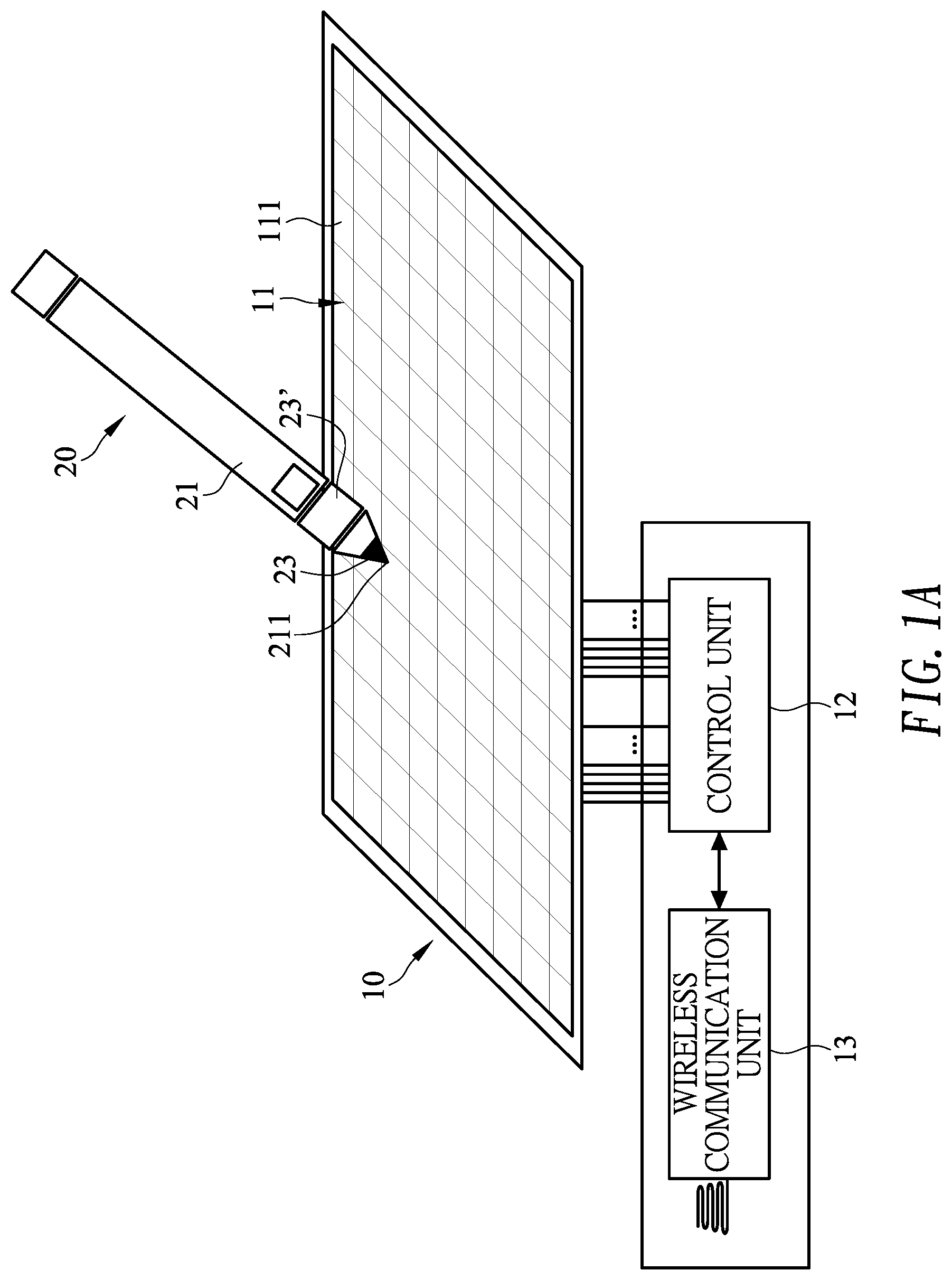
FIG. 1A is an illustrative view of a first embodiment of a touch system in accordance with the present invention;
FIG. 1B is an illustrative view of a second embodiment of a touch system in accordance with the present invention;
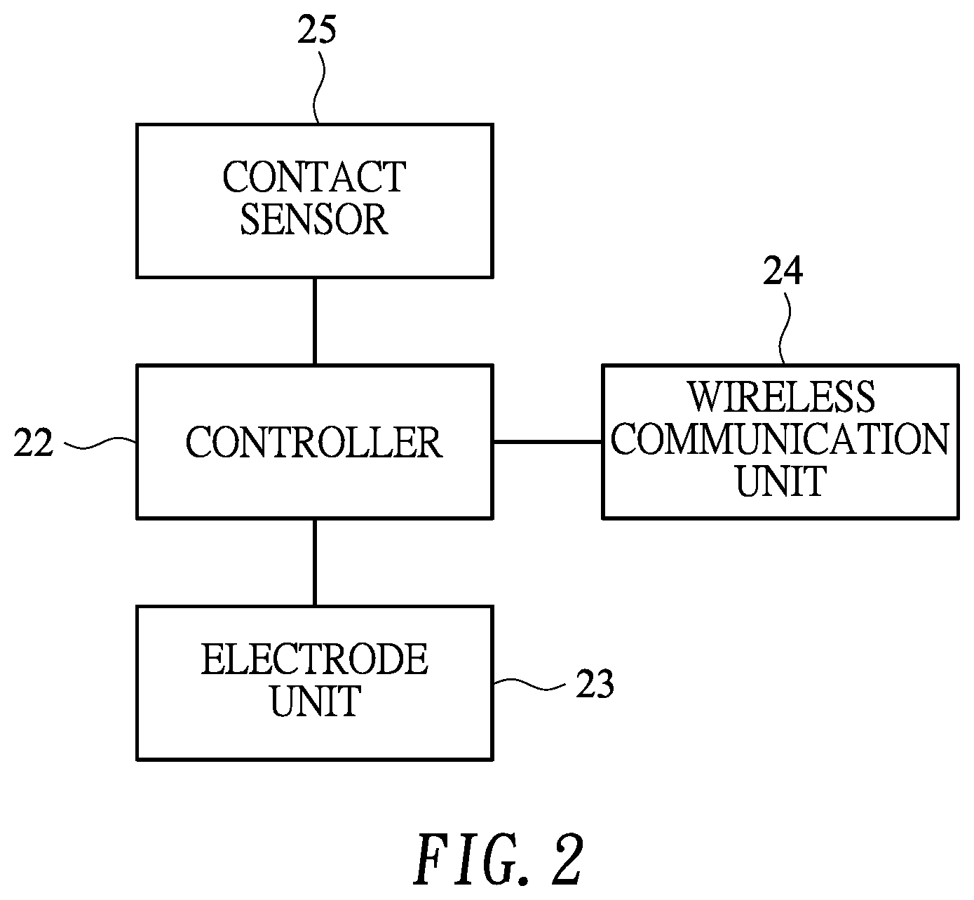
FIG. 2 is a partial block diagram of an input device of the touch system in FIGS. 1A and 1B;
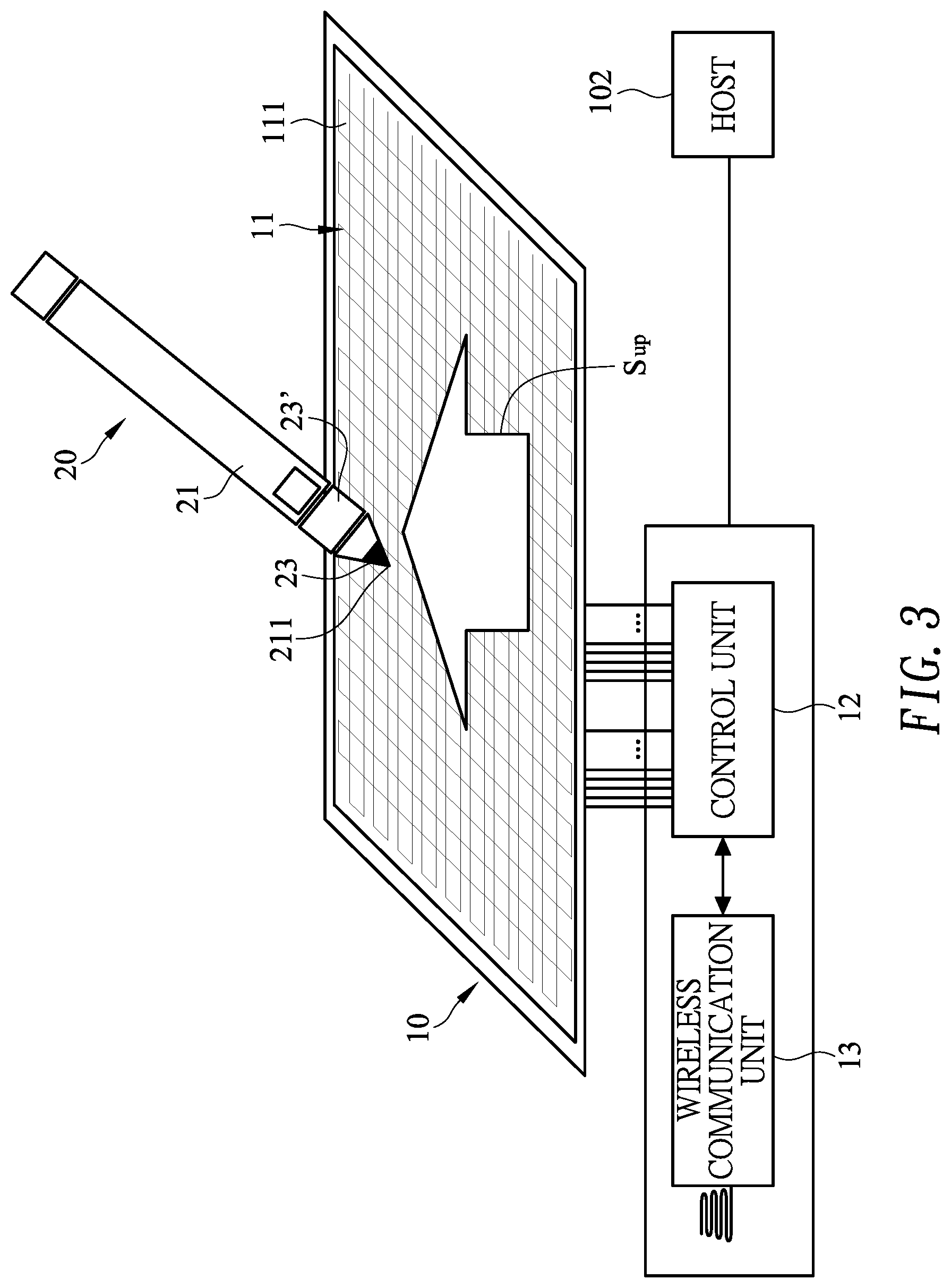
FIG. 3 is an operational illustrative view of the touch system in FIG. 1, shown the uplink signal transmitting;
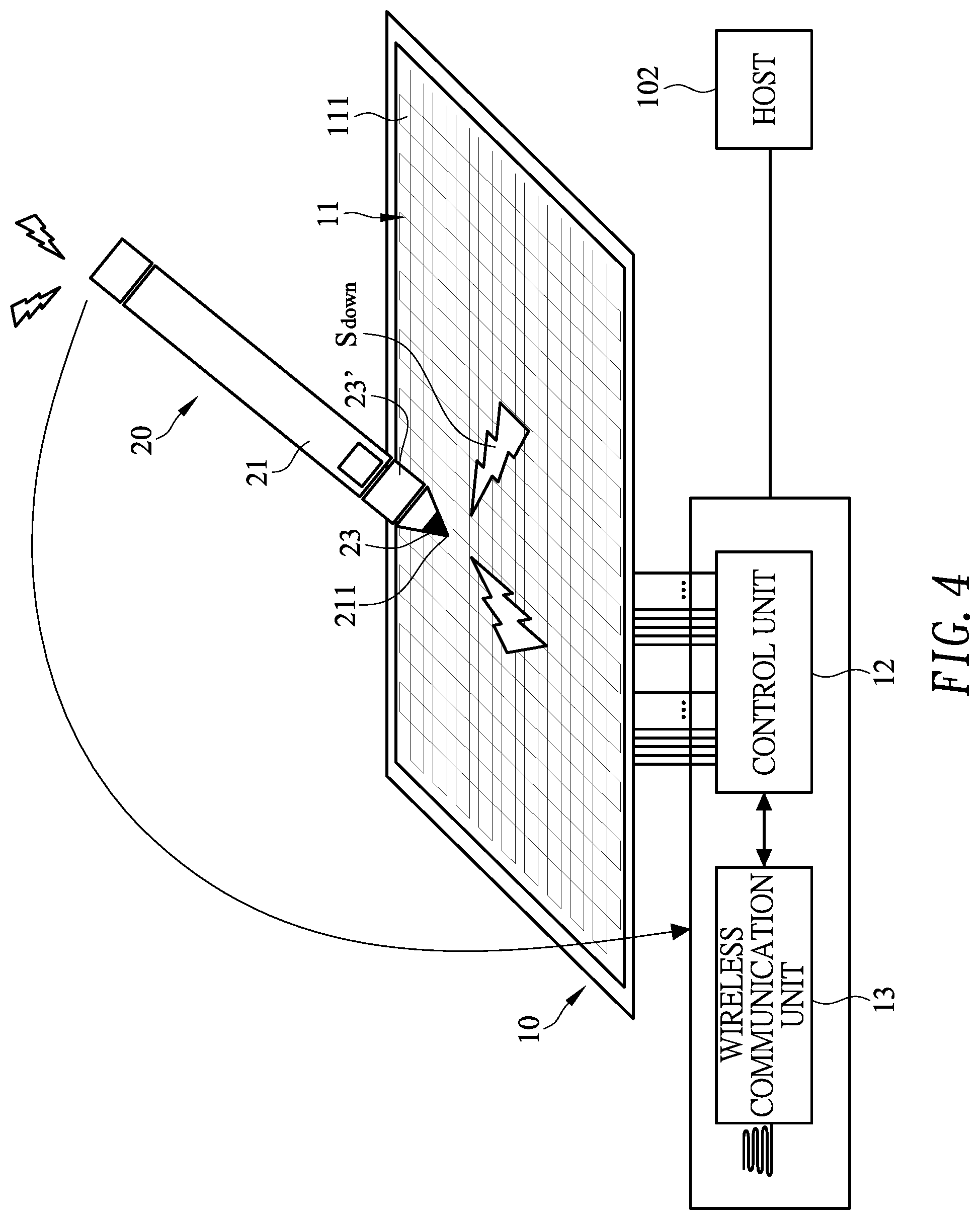
FIG. 4 is an operational illustrative view of the touch system in FIG. 1, shown the downlink signal and side information transmitting;
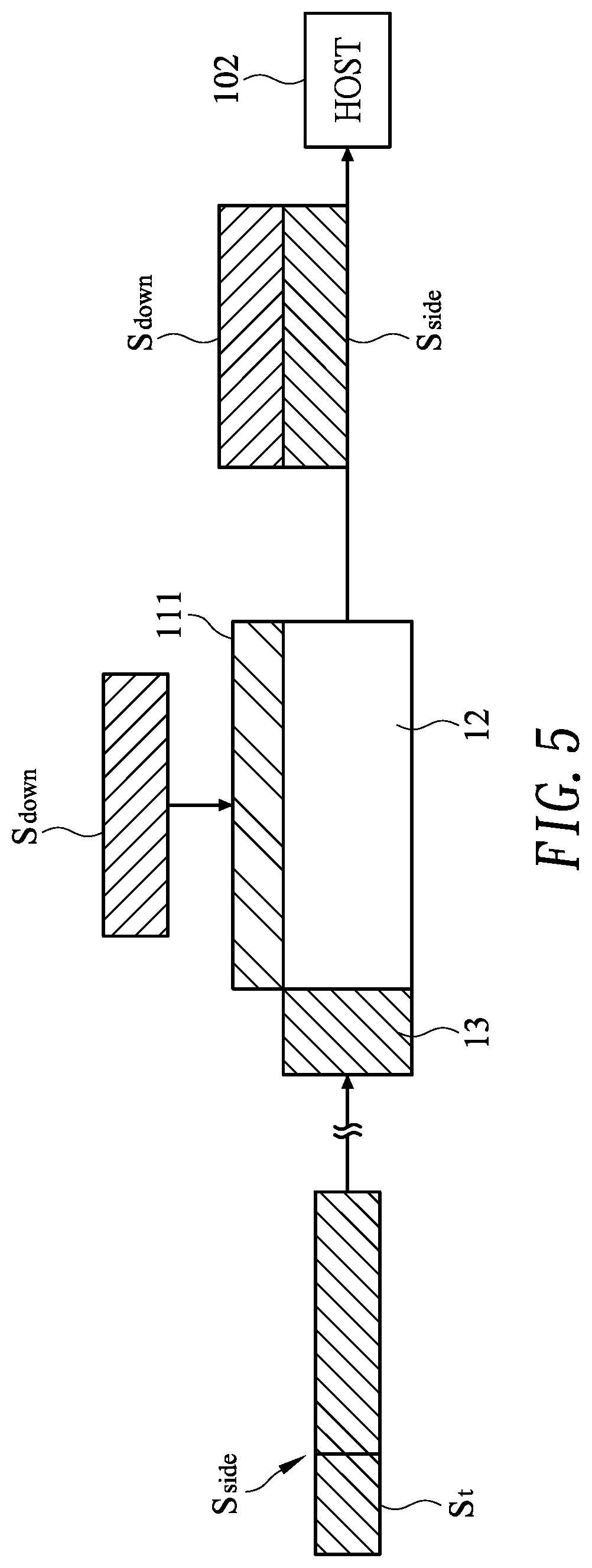
FIGS. 5 and 7 are illustrative views to show the signals transmitted in the touch system of the touch system in FIGS. 1A and 1B;
FIG. 6 is an illustrative view to show the signals transmitted path of the touch system in FIGS. 1A and 1B;
FIG. 8 is an illustrative view of a first embodiment of a downlink signal of the touch system in FIGS. 1A and 1B; and
FIG. 9 is an illustrative view of a second embodiment of a downlink signal of the touch system in FIGS. 1A and 1B.
DETAILED DESCRIPTION OF THE EMBODIMENTS
With reference to FIG. 1A, a touch system in accordance with the present invention comprises a touch device 10 and an input device 20.
The touch device 10 has a touch interface 11, a control unit 12 and a wireless communication unit 13. The touch interface 11 has multiple touch electrodes 111. The touch electrodes 111 and the wireless communication unit 13 electrically connect respectively to the control unit 12. The touch interface 11 includes a touch contact surface. The touch electrodes 111 are disposed under the touch contact surface and are arranged in a matrix including electrodes along X and Y directions to transmit and receive signals. The touch electrodes 111 may be formed by indium tin oxide (ITO) or other electrical conductors, or may be formed by a common electrode layer of a display, or their combination. The wireless communication unit 13 is used to transmit and receive signals. In one embodiment as shown in FIG. 1A, the wireless communication unit 13 and the control unit 12 are integrated on a circuit board. In another embodiment as shown in FIG. 1B, the touch device 10 comprises a host 102. The control unit 12 of this embodiment is independent of the host 102 for performing touch detection, and the wireless communication unit 13 is integrated into a processor of the host 102. In one embodiment, the wireless communication unit 13 is a Bluetooth communication unit or a Zigbee communication unit.
With reference to FIGS. 1A and 2, the input device 20 comprises a body 21, a controller 22, at least one electrode unit 23, a wireless communication unit 24 and a contact sensor 25. The body 21 has a contact end 211. The input device 20 may be a stylus and the contact end 211 is disposed on a tip of the stylus. The controller 22, the electrode unit 23 and the wireless communication unit 24 are mounted in the body 21. The electrode unit 23, the wireless communication unit 24 and the contact sensor 25 electrically connect respectively to the controller 22. In this embodiment, the input device 20 has two electrode units 23, 23'. One of the electrode units 23 is used to transmit and receive signals, and the other one of the electrode units 23' is used to receive signals. In another embodiment, the input device 20 may only have single electrode unit 23 disposed near an end of the input device 20 to transmit and receive signals at different times. The wireless communication unit 24 is used to transmit signals. The contact sensor 25 is used to sense if the contact end 211 of the input device 20 contacts the touch contact surface of the touch device 10. In one embodiment, the wireless communication unit 24 is a Bluetooth communication unit or a Zigbee communication unit. In one embodiment, the contact sensor 25 is a pressure sensor to sense the pressure when the contact end 211 of the input device 20 contacts the touch interface 11 of the touch device 10.
With reference to FIG. 3, the touch device 10 periodically sends an uplink signal S.sub.up according to the protocol when the touch device 10 works. The uplink signal S.sub.up comprises a synchronization information and a time stamp. The synchronization information includes a time for the input device 20 to send a downlink signal S.sub.down. The time stamp is used to indicate a sent time for sending the uplink signal S.sub.up and may be demonstrated in different ways. For example, the time stamp is demonstrated by a relative time, such as "5m31s after booting." For another example, the time stamp is demonstrated by an absolute time, such as "2019 Jun. 6, 17 15:41." For yet another example, the time stamp is demonstrated by a time serial number such as "53.sup.th period." In one embodiment, the touch device 10 sends the uplink signal S.sup.up once in each frame, and the time stamp in the uplink signal S.sup.up indicates this frame. In one embodiment, a frame of the touch device 10 means all of the touch electrodes 111 are finish their touch sensing.
With reference to FIGS. 2 to 5, the input device 20 receives the uplink signal S.sup.up sent from the touch device 10 via the electrode unit 23' when the input device 20 hovers above or contacts the touch device 10. Then the input device 20 sends said downlink signal S.sub.down via another electrode unit 23 and said downlink signal S.sub.down is received by the touch electrodes 111 of the touch device 10 so that the positions and the moving tracks of the input device 20 on the touch device 10 is determined. The input device 20 also sends a side information S.sub.side via the wireless communication unit 24 of the input device 20. The side information S.sub.side mainly includes at least one of the information such as a pressure information of the input device 20 contacting the touch device 10, a tilt angle information of the input device 20, a power information of the input device 20, and a button information of the input device 20, and the like. The side information S.sub.side also includes the time stamp S.sub.t to indicate the time. The side information S.sub.side including the time stamp S.sub.t are received by the wireless communication unit 13 of the touch device 10. The control unit 12 of the touch device 10 combines the side information S.sub.side and the corresponding downlink signal S.sub.down based on the time stamp S.sub.t of the side information S.sub.side, and then proceeds subsequent determination. In one embodiment, in each frame, the wireless communication unit 24 of the input device 20 sends the side information S.sub.side once, and the time stamp S.sub.t included in the side information S.sub.side indicates the time corresponding to the uplink signal S.sup.up received in this frame. In another embodiment, the wireless communication unit 24 of the input device 20 transmits the side information S.sub.side a plurality of times in each frame. Besides the time stamp S.sub.t corresponding to the uplink signal S.sup.up received in that frame, the side information S.sub.side sent in each frame, includes a sequential stamp indicating the sequence of the side information S.sub.side in that frame. For example, the wireless communication unit 24 of the input device 20 sends the side information S.sub.side four times in the frame. The first side information S.sub.side includes, in addition to the aforementioned time stamp S.sub.t, a sequential stamp indicating the first side information S.sub.side of the frame. The rest side information S.sub.side is also like this and described repeatedly.
With reference to FIG. 6 with FIGS. 2 and 5, one frame is used as an example. The electrode unit 23' of the input device 20 receives the uplink signal S.sup.up sent from the touch electrodes 111 of the touch device 10. The uplink signal S.sup.up includes a timestamp S.sub.t1 indicating the transmission time. The touch device 10 then enters a receiving mode RX, and is ready to receive the signal sent from the electrode unit 23 of the input device 20 via the touch electrodes 111. When the uplink signal S.sub.up is received by the input device 20, the input device 20 transmits the first downlink signal S.sub.down1, the second downlink signal S.sub.down2, and the third downlink signal S.sub.down3 through the electrode unit 23 according to the synchronization information in the uplink signal S.sup.up in the frame. The touch electrode 111 of the touch device 10 receives the downlink signals S.sub.down1, S.sub.down2, and S.sub.down3 in the frame. The downlink signals S.sub.down1, S.sub.down2, and S.sub.down3 are used to determine the position of the input device 20 relative to the touch device 10. The downlink signals S.sub.down1, S.sub.down2, and S.sub.down3 may include information for determining the location of the input device 20 relating to the touch device 10, and may include related information of the input device, for example, identification (ID), etc. In addition, in the frame, the wireless communication unit 24 of the input device 20 transmits the first side information S.sub.side1, the second side information S.sub.side2, and the third side information S.sub.side3. The side information S.sub.side1, the second side information S.sub.side2, and the third side information and S.sub.side3 are received by the wireless communication unit 13 of the touch device 10. The side information S.sub.side1, S.sub.side2 and S.sub.side3 may be the aforementioned pressure information, tilt angle information or button information and the like. Moreover, the first side information S.sub.side1 includes a first timestamp S.sub.t1-1, the second side information S.sub.side2 includes a second timestamp S.sub.t1-2, and the third side information S.sub.side3 includes a third timestamp S.sub.t1-3. The first, second, and third time stamps S.sub.t1-1, S.sub.t1-2, and S.sub.t1-3 respectively include a time stamp S.sub.t1 included in the uplink signal S.sup.up corresponding to that frame, and further include the sequential information of the side information.
When the touch device 10 receives the downlink signals S.sub.down1, S.sub.down2, and S.sub.down3, the touch device 10 fills them into the record part of the firmware corresponding to the frame. For example, if the touch device 10 transmits the uplink signal S.sup.up in a first frame, the touch device 10 fills the downlink signals S.sub.down1, S.sub.down2, and S.sub.down3 into the record part of the firmware corresponding to the first frame after receiving the downlink signals S.sub.down1, S.sub.down2, and S.sub.down3. In addition, according to the time stamp S.sub.t1, the side information S.sub.side1, S.sub.side2, and S.sub.side3 are filled into the other record part of the firmware corresponding to the first frame and the time stamp St.sub.1 when the touch device 10 receives the side information S.sub.side1, S.sub.side2, and S.sub.side3. Thereby recording the coordinates, pressure information, button information, ID, etc. of the input device 20 in the first frame. When the information is integrated, the integrated content is transmitted to the host 102.
The wireless communication unit 13 of the touch device 10 may not receive the side information S.sub.side in the frame due to the delay of the signal when the wireless communication unit 24 of the input device 20 transmits the side information S.sub.side. For example, as shown in FIG. 6, the third side information S.sub.side3 is received by the wireless communication unit 13 of the touch device 10 in the next frame. However, since the third time stamp S.sub.t1-3 is included in the third side information S.sub.side3, the touch device 10 still identifies the third side information S.sub.side3 received at this time through the third time stamp S.sub.t1-3 to which the frame it belongs to. Therefore, when the third side information S.sub.side3 is filled in the firmware, not receiving the third side information S.sub.side3 in its original frame does not cause the touch device 10 to record the related information to the wrong record part.
Therefore, the use of the aforementioned time stamp S.sub.t effectively ensures that the side information S.sub.side can be combined with the downlink signal S.sub.down corresponding to the same frame. The user's operation can be correctly presented to avoid data loss or the appearance of ink leakage due to delay in wireless transmission.
With reference to FIGS. 2, 4 and 7, the input device 20 performs writing on the touch contact surface of the touch device 10, and any of the wireless communication units 13 and 24 of the touch device 10 and the input device 20 suddenly fails or the wireless communication signal is interfered so that the side information S.sub.side is not sent or received normally. At this time, the contact sensor 25 of the input device 20 senses whether the contact end 211 of the input device 20 contacts the touch contact surface of the touch device 10 to obtain a message for assisting the determination, i.e. the downlink signal S.sub.down further includes a contact message S.sub.c. In one embodiment, the contact sensor 25 is the pressure sensor. When the pressure value sensed by the contact sensor 25 is greater than a threshold (for example, the threshold value is 0), the input device 20 is determined that the contact end 211 contacts the touch device 10, and vice versa.
When the contact end 211 of the input device 20 contacts the touch device 10, the contact message S.sub.c is presented as a first message. When the contact end 211 of the input device 20 does not contact the touch device 10, the contact message S.sub.c is presented as a second message. The first message is different to the second message. For example, the first message may be 0 and the second message may be 1. The touch device 10 knows whether the contact end 211 of the input device 20 contacts the touch device 10 by using the contact message S.sub.c included in the received downlink signal S.sub.down. In one embodiment, a simulated side information S.sub.side* can be derived from the received contact information S.sub.c and the previously received side information S.sub.side, and the user experience can be maintained through the simulated side information S.sub.side*. For example, the wireless communication unit 13 of the touch device 10 receives the side information S.sub.side normally in the 1.sup.st to 5.sup.th frames, but does not receive the side information S.sub.side in the 6.sup.th frame. A simulated side information S.sub.side* is determined through the contact message S.sub.c received in the 6.sup.th frame and the side information S.sub.side received in at least one of the previous frames. For example, the pressure value of the 5.sup.th frame or the average pressure value of the 3.sup.rd, 4.sup.th, 5.sup.th frames is directly used as the pressure value of the 6.sup.th frame (that is, the simulation side information S.sub.side*), or a speed of the movement of the contact end 211 of the input device 20 is used as the weight value to calculate the pressure value of the 6.sup.th frame based on the pressure value in the side information of the previous frame, wherein the speed is inversely proportional to the weight value of the pressure value.
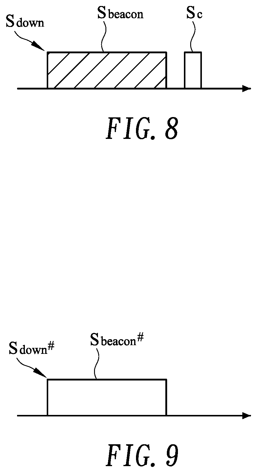
The contact message S.sub.c included in the downlink signal S.sub.down can be presented in different manners. In one embodiment as shown in FIG. 8, the downlink signal S.sub.down includes a beacon message S.sub.beacon and the contact message S.sub.c. When the contact end 211 of the input device 20 contacts the touch device 10, the contact message S.sub.c is presented as the first message. When the contact end 211 of the input device 20 does not contact the touch device 10, the contact message S.sub.c is presented as the second message. In another embodiment as shown in FIG. 9, the downlink signal S.sub.down # includes a beacon message S.sub.beacon #, and the beacon message S.sub.beacon # presents the contact message S.sub.c at different frequencies. When the contact end 211 of the input device 20 contacts the touch device 10, the beacon message S.sub.beacon # presents at a first frequency. When the contact end 211 of the input device 20 does not contact the touch device 10, the beacon message S.sub.beacon # presents at a second frequency.
Therefore, the touch device 10 realizes whether the input device 20 has contact with the touch device 10 by using the contact information S.sub.c regardless of whether the wireless communication unit is used or the wireless communication unit is disabled. The pressure of the input device 20 corresponding to the touch device 10 and other possible side information can be further simulated by an algorithm.
Even though numerous characteristics and advantages of the present invention have been set forth in the foregoing description, together with details of the structure and features of the invention, the disclosure is illustrative only. Changes may be made in the details, especially in matters of shape, size, and arrangement of parts within the principles of the invention to the full extent indicated by the broad general meaning of the terms in which the appended claims are expressed.
* * * * *
D00000
D00001
D00002
D00003
D00004
D00005
D00006
D00007
D00008
D00009
XML
uspto.report is an independent third-party trademark research tool that is not affiliated, endorsed, or sponsored by the United States Patent and Trademark Office (USPTO) or any other governmental organization. The information provided by uspto.report is based on publicly available data at the time of writing and is intended for informational purposes only.
While we strive to provide accurate and up-to-date information, we do not guarantee the accuracy, completeness, reliability, or suitability of the information displayed on this site. The use of this site is at your own risk. Any reliance you place on such information is therefore strictly at your own risk.
All official trademark data, including owner information, should be verified by visiting the official USPTO website at www.uspto.gov. This site is not intended to replace professional legal advice and should not be used as a substitute for consulting with a legal professional who is knowledgeable about trademark law.