Projection optical system and projection apparatus that enlarge and project an image displayed on a display
Masui , et al. November 24, 2
U.S. patent number 10,845,695 [Application Number 16/395,370] was granted by the patent office on 2020-11-24 for projection optical system and projection apparatus that enlarge and project an image displayed on a display. This patent grant is currently assigned to Konica Minolta, Inc.. The grantee listed for this patent is Konica Minolta, Inc.. Invention is credited to Kazuhiko Inoue, Atsuo Masui, Atsushi Matsuura.


View All Diagrams
| United States Patent | 10,845,695 |
| Masui , et al. | November 24, 2020 |
Projection optical system and projection apparatus that enlarge and project an image displayed on a display
Abstract
A projection optical system that enlarges and projects an image displayed on an image display includes: a first optical system; and a second optical system. The projection optical system is a monofocal lens or a zoom lens. The first optical system and the second optical system are arranged, in order starting with the first optical system, from an enlargement side of the projection optical system. The second optical system forms an intermediate image of the image between the first optical system and the second optical system. The first optical system enlarges and projects the intermediate image. The first optical system includes: a first-A optical system and a first-B optical system in order from the enlargement side; and a reflecting optical element that bends a light path between the first-A optical system and the first-B optical system.
| Inventors: | Masui; Atsuo (Sakai, JP), Inoue; Kazuhiko (Sakai, JP), Matsuura; Atsushi (Nishinomiya, JP) | ||||||||||
|---|---|---|---|---|---|---|---|---|---|---|---|
| Applicant: |
|
||||||||||
| Assignee: | Konica Minolta, Inc. (Tokyo,
JP) |
||||||||||
| Family ID: | 1000005202519 | ||||||||||
| Appl. No.: | 16/395,370 | ||||||||||
| Filed: | April 26, 2019 |
Prior Publication Data
| Document Identifier | Publication Date | |
|---|---|---|
| US 20190250495 A1 | Aug 15, 2019 | |
Related U.S. Patent Documents
| Application Number | Filing Date | Patent Number | Issue Date | ||
|---|---|---|---|---|---|
| 15954156 | Apr 16, 2018 | 10317786 | |||
Foreign Application Priority Data
| Apr 20, 2017 [JP] | 2017-083758 | |||
| Current U.S. Class: | 1/1 |
| Current CPC Class: | G02B 17/0896 (20130101); G02B 13/04 (20130101); G02B 15/177 (20130101); G02B 13/16 (20130101); G03B 21/14 (20130101); G03B 21/28 (20130101); G02B 17/008 (20130101); G02B 13/22 (20130101) |
| Current International Class: | G03B 21/14 (20060101); G03B 21/28 (20060101); G02B 15/177 (20060101); G02B 17/08 (20060101); G02B 17/00 (20060101); G02B 13/04 (20060101); G02B 13/22 (20060101); G02B 13/16 (20060101) |
References Cited [Referenced By]
U.S. Patent Documents
| 7009765 | March 2006 | Gohman |
| 7224535 | May 2007 | Neil |
| 9041848 | May 2015 | Inoko |
| 9523907 | December 2016 | Ode |
| 10338356 | July 2019 | Amano |
| 10386618 | August 2019 | Amano |
| 10401596 | September 2019 | Masui |
| 10401597 | September 2019 | Amano |
| 2004/0032653 | February 2004 | Gohman |
| 2008/0130106 | June 2008 | Gohman |
| 2009/0207502 | August 2009 | Cho |
| 2009/0244701 | October 2009 | Gohman |
| 2012/0120484 | May 2012 | Konuma |
| 2014/0036142 | February 2014 | Inoko |
| 2015/0234167 | August 2015 | Ode |
| 2015/0268453 | September 2015 | Oe |
| 2016/0246035 | August 2016 | Amano |
| 2016/0246036 | August 2016 | Amano |
| 2017/0153427 | June 2017 | Masui |
| 205539675 | Aug 2016 | CN | |||
Other References
|
Office Action issued in corresponding Chinese Patent Application No. 201810335281.4 dated Mar. 20, 2020, with translation (11 pages). cited by applicant. |
Primary Examiner: Le; Bao-Luan Q
Attorney, Agent or Firm: Osha Bergman Watanabe & Burton LLP
Parent Case Text
CROSS-REFERENCE TO RELATED APPLICATIONS
This application is a continuation of U.S. patent application Ser. No. 15/954,156 filed on Apr. 16, 2018, which claims priority from Japanese patent Application No. 2017-083758 filed on Apr. 20, 2017, the contents of which are incorporated by reference in their entirety.
Claims
What is claimed is:
1. A projection optical system enlarges and projects an image displayed on an image display surface, the projection optical system comprising: a first optical system; and a second optical system, wherein the projection optical system is a monofocal lens or a zoom lens, the first optical system and the second optical system are arranged, in order starting with the first optical system, from an enlargement side of the projection optical system, the second optical system forms an intermediate image of the image between the first optical system and the second optical system, the first optical system enlarges and projects the intermediate image, the first optical system comprises: a first-A optical system and a first-B optical system in order from the enlargement side; and a reflecting optical element that bends a light path between the first-A optical system and the first-B optical system, the first-A optical system comprises: a negative front group comprising a negative lens closest to a reduction side; and a rear group comprising three positive lenses, and the light path is bent only once by 90 degrees.
2. The projection optical system according to claim 1, wherein the front group comprises one or less positive lens.
3. The projection optical system according to claim 1, wherein the first-A optical system comprises a first focusing part that moves during focusing, and the first-B optical system or the second optical system comprises a second focusing part that moves during focusing.
4. The projection optical system according to claim 1, wherein the first optical system and the second optical system are on a same optical axis.
5. The projection optical system according to claim 1, wherein the second optical system and an entirety of the projection optical system are telecentric on the reduction side.
6. The projection optical system according to claim 1, wherein the projection optical system is a zoom lens that zooms by moving a lens group comprising a portion of the second optical system along an optical axis.
7. The projection optical system according to claim 1, wherein the reflecting optical element is a plane mirror.
8. The projection optical system according to claim 1, wherein the reflecting optical element is a triangular prism, and an oblique side of the triangular prism is a reflecting surface that bends the light path.
9. A projection apparatus comprising: an image display element comprising an image display surface; and a projection optical system that enlarges and projects an image displayed on the image display surface, wherein the projection optical system comprises a first optical system and a second optical system in order from an enlargement side of the projection optical system, the second optical system forms an intermediate image of the image between the first optical system and the second optical system, the first optical system enlarges and projects the intermediate image, the first optical system comprises: a first-A optical system and a first-B optical system in order from the enlargement side; and a reflecting optical element that bends a light path between the first-A optical system and the first-B optical system, the first-A optical system comprises: a negative front group comprising a negative lens closest to a reduction side; and a rear group comprising three positive lenses, and the light path is bent only once by 90 degrees.
10. The projection apparatus according to claim 9, wherein a lens closest to a screen side in the projection optical system is disposed closest to the screen side in an entirety of the projection apparatus.
11. The projection apparatus according to claim 9, wherein the reflecting optical element is a plane mirror.
12. The projection apparatus according to claim 9, wherein the reflecting optical element is a triangular prism, and an oblique side of the triangular prism is a reflecting surface that bends the light path.
Description
TECHNICAL FIELD
The present invention relates to a projection optical system and a projection apparatus, and more particularly, to a projection optical system suitable for enlarging and projecting, on a screen, a display image of an image display element such as a digital micromirror device or a liquid crystal display (LCD) with a wide angle of view exceeding 100.degree. and a projection apparatus having the projection optical system.
BACKGROUND
In recent years, a projection apparatus with a wide angle of view that can perform large screen projection with a short projection distance has been required. In order to realize such a projection apparatus with a wide angle of view, it is effective to adopt a relay-type projection optical system that forms an intermediate image at a time. However, in this case, the total length of the projection optical system is extended, and the projection apparatus main body is also lengthened, so that the effect of shortening the projection distance becomes small. As a countermeasure therefor, a projection optical system with a wide angle of view in which the total length of the projection apparatus main body is shortened by bending a projection light path is proposed in JP 2008-536175 A and JP 2006-523318 A.
Herein, in the relay-type projection optical system, an enlargement-side portion of the intermediate image is set as a first optical system, and a reduction-side portion of the intermediate image is set as a second optical system. In the projection optical system described in JP 2008-536175 A, the light path in the first optical system is bent, and the light path between the first optical system and the second optical system is also bent. Therefore, many optical elements for bending the light path are used, so that cost is increased. In the projection optical system described in JP 2006-523318 A, the light path is not bent in the first optical system, but the light path is bent at the position of the intermediate image. Therefore, in order to shorten the projection optical system in the projection direction, it is necessary to shorten the first optical system for projecting the intermediate image onto the screen, and thus, it is difficult to achieve both of the wide angle of view of the projection and the high image quality of the projected image.
SUMMARY
One or more embodiments are directed to a projection optical system that enlarges and projects an image displayed on an image display surface. The projection optical system includes: a first optical system; and a second optical system. The projection optical system is a monofocal lens or a zoom lens. The first optical system and the second optical system are arranged, in order starting with the first optical system, from an enlargement side of the projection optical system. The second optical system forms an intermediate image of the image between the first optical system and the second optical system. The first optical system enlarges and projects the intermediate image. The first optical system includes: a first-A optical system and a first-B optical system in order from the enlargement side; and a reflecting optical element that bends a light path between the first-A optical system and the first-B optical system. The first-A optical system includes: a negative front group including a negative lens closest to a reduction side; and a rear group including three positive lenses. The light path is bent only once by 90 degrees.
One or more embodiments are directed to a projection apparatus that includes: an image display element including an image display surface; and a projection optical system that enlarges and projects an image displayed on the image display surface. The projection optical system includes a first optical system and a second optical system in order from an enlargement side of the projection optical system. The second optical system forms an intermediate image of the image between the first optical system and the second optical system. The first optical system enlarges and projects the intermediate image. The first optical system includes: a first-A optical system and a first-B optical system in order from the enlargement side; and a reflecting optical element that bends a light path between the first-A optical system and the first-B optical system. The first-A optical system includes: a negative front group including a negative lens closest to a reduction side; and a rear group including three positive lenses. The light path is bent only once by 90 degrees.
BRIEF DESCRIPTION OF THE DRAWINGS
The advantages and features provided by one or more embodiments of the invention will become more fully understood from the detailed description given herein below and the appended drawings which are given by way of illustration only, and thus are not intended as a definition of the limits of the present invention:
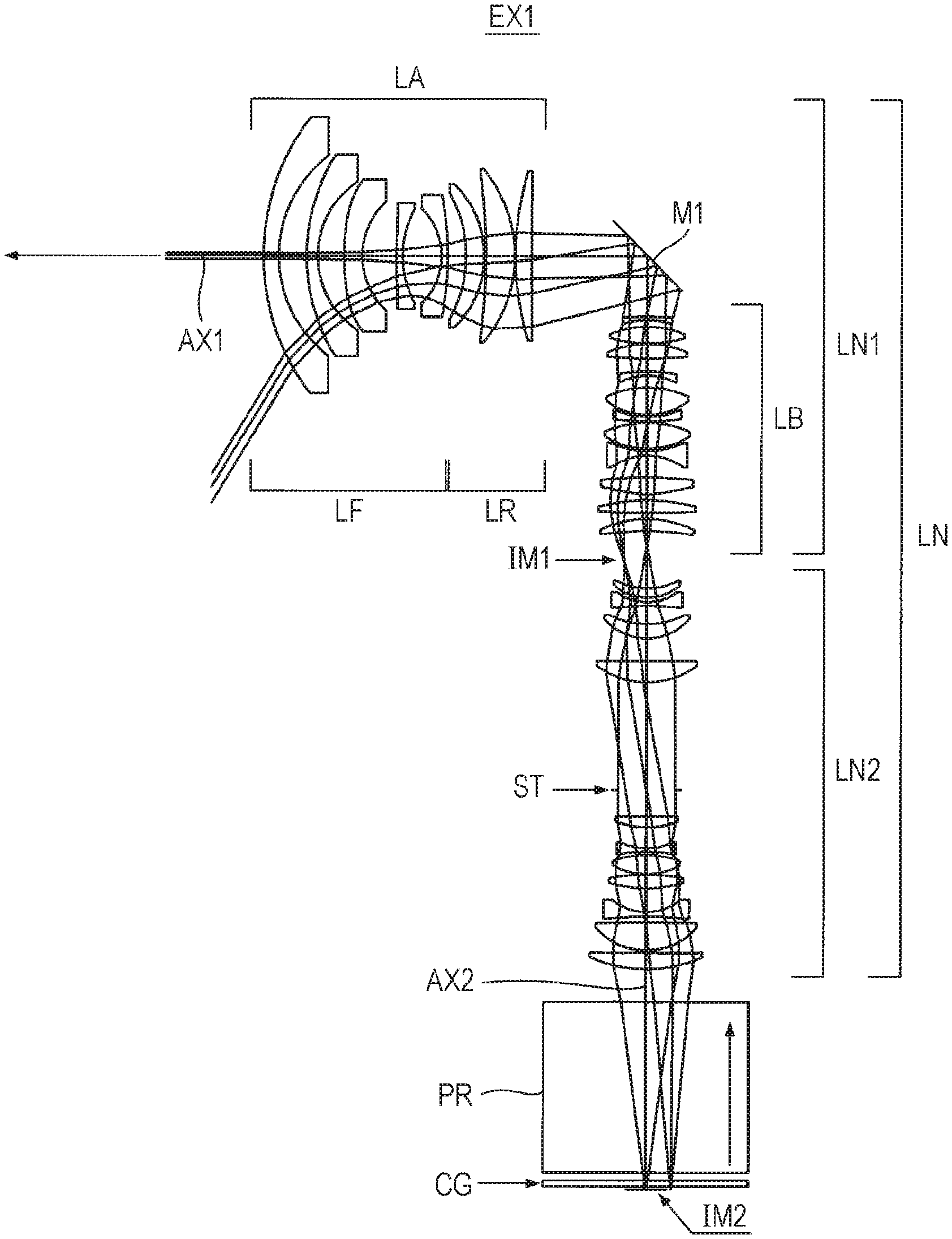
FIG. 1 is a light path diagram according to one or more embodiments of the invention (Example 1).
FIG. 2 is a light path diagram according to one or more embodiments of the invention (Example 2).
FIG. 3 is a light path diagram according to one or more embodiments of the invention (Example 3).
FIG. 4 is a light path diagram according to one or more embodiments of the invention (Example 4).
FIG. 5 is an optical configuration diagram according to one or more embodiments of the invention (Example 1).
FIG. 6 is an optical configuration diagram according to one or more embodiments of the invention (Example 2).
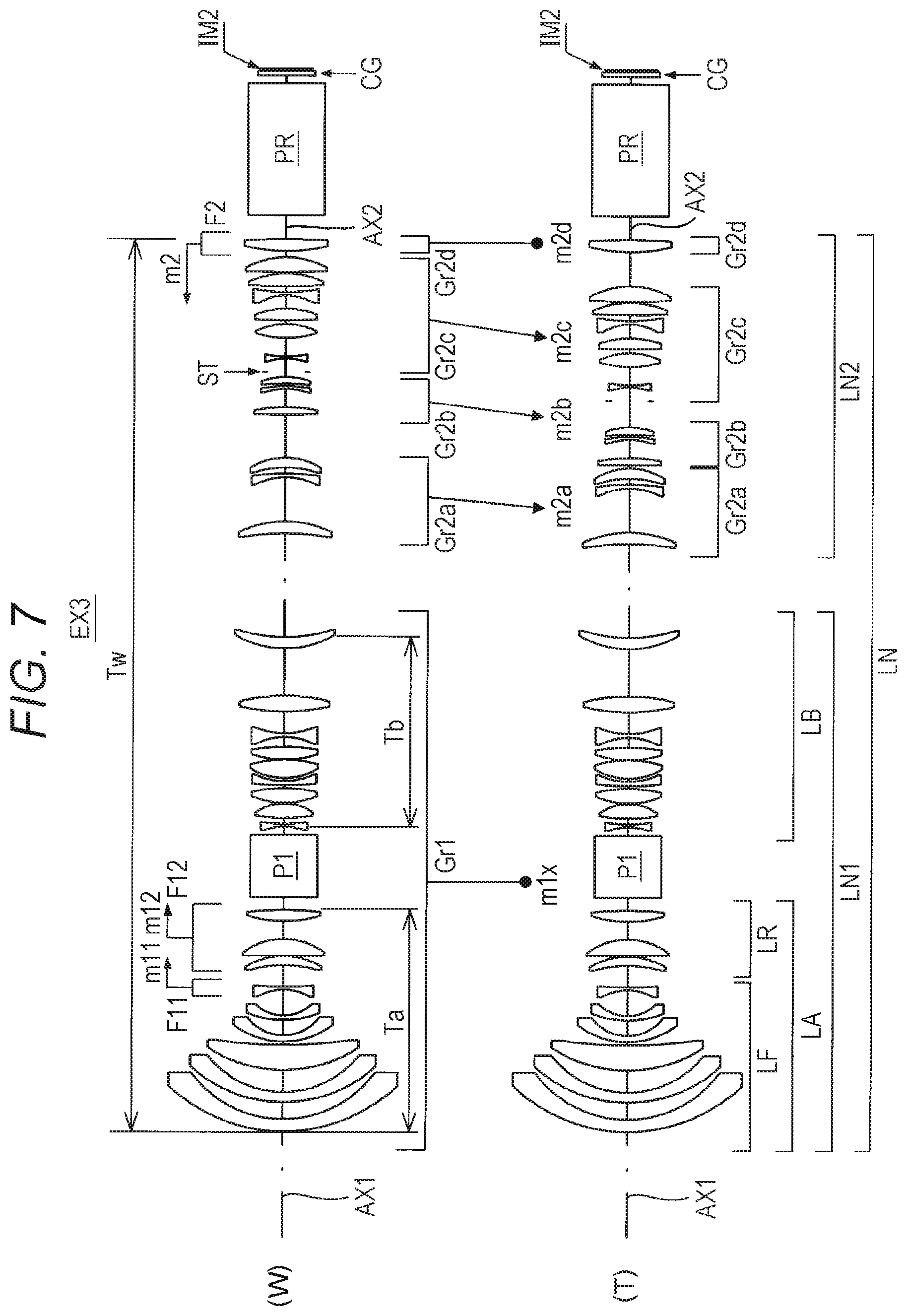
FIG. 7 is an optical configuration diagram according to one or more embodiments of the invention (Example 3).
FIG. 8 is an optical configuration diagram according to one or more embodiments of the invention (Example 4).
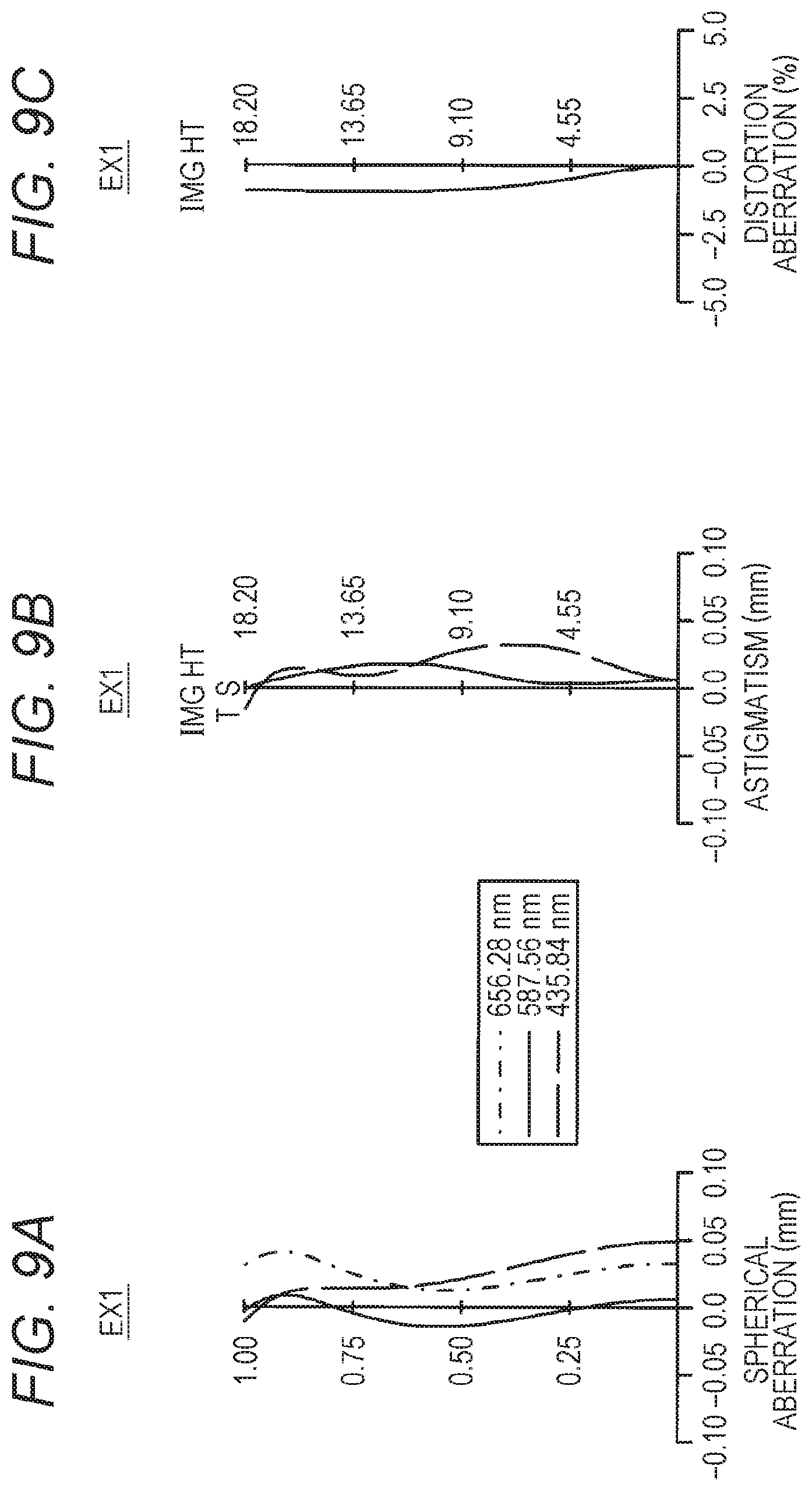
FIGS. 9A to 9C are aberration diagrams of Example 1.
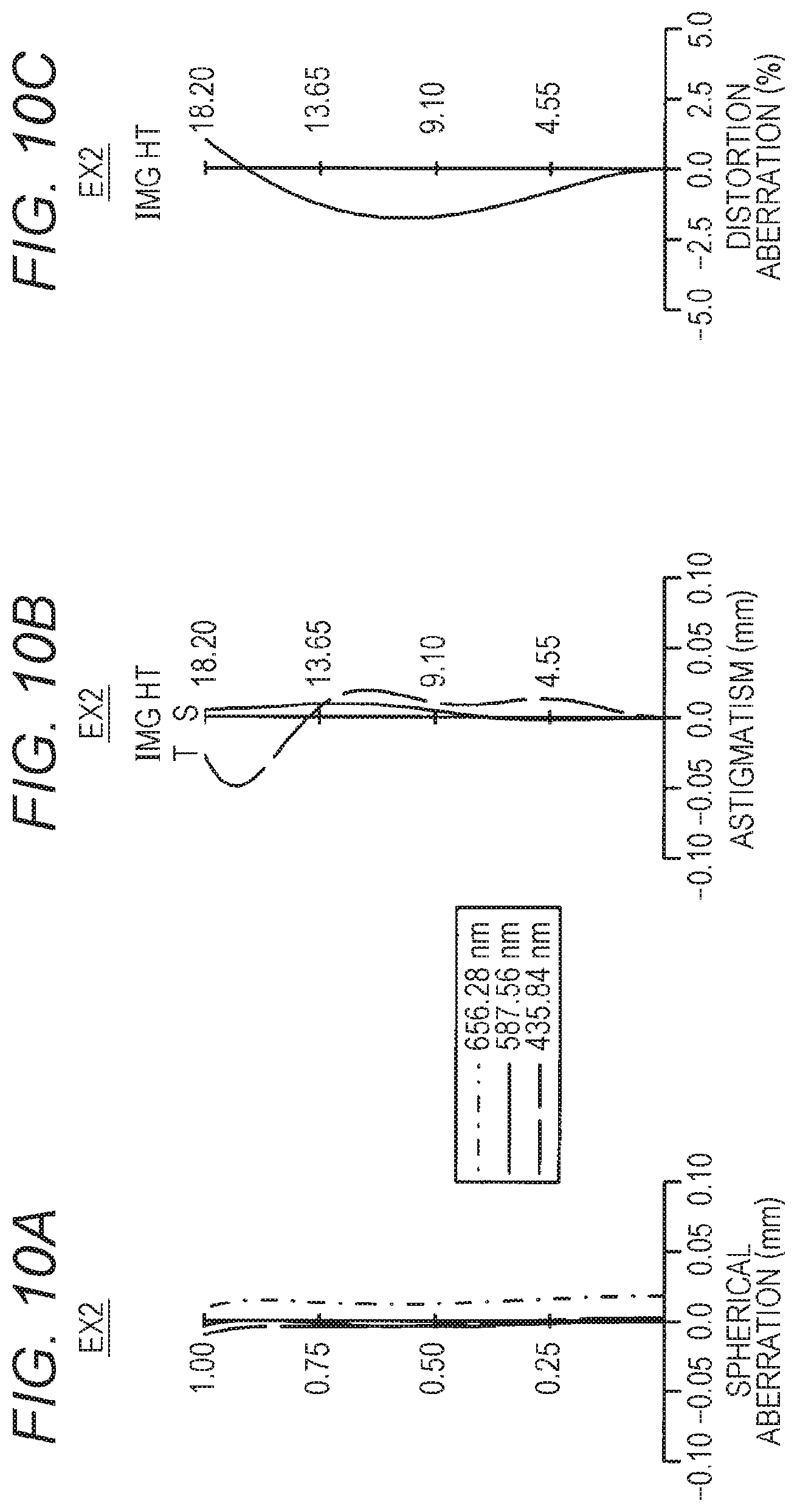
FIGS. 10A to 10C are aberration diagrams of Example 2.
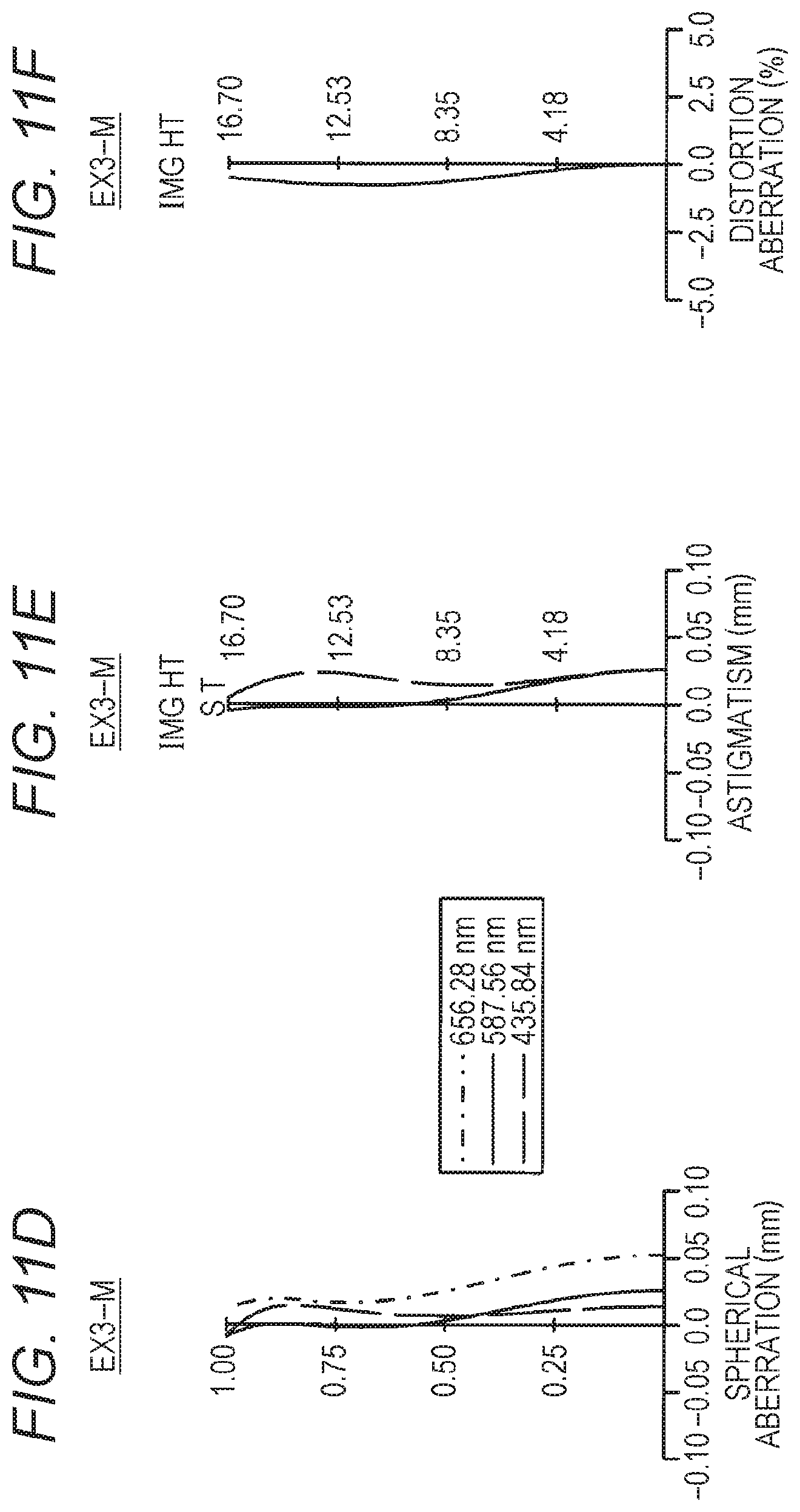
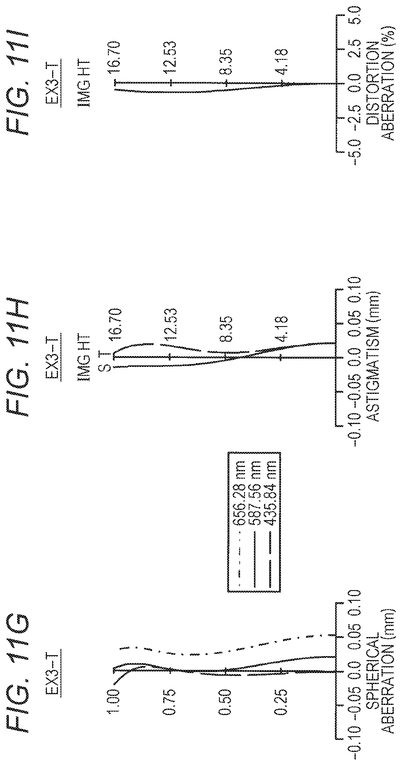
FIGS. 11A to 11I are aberration diagrams of Example 3.
FIGS. 12A to 12C are aberration diagrams of Example 4.
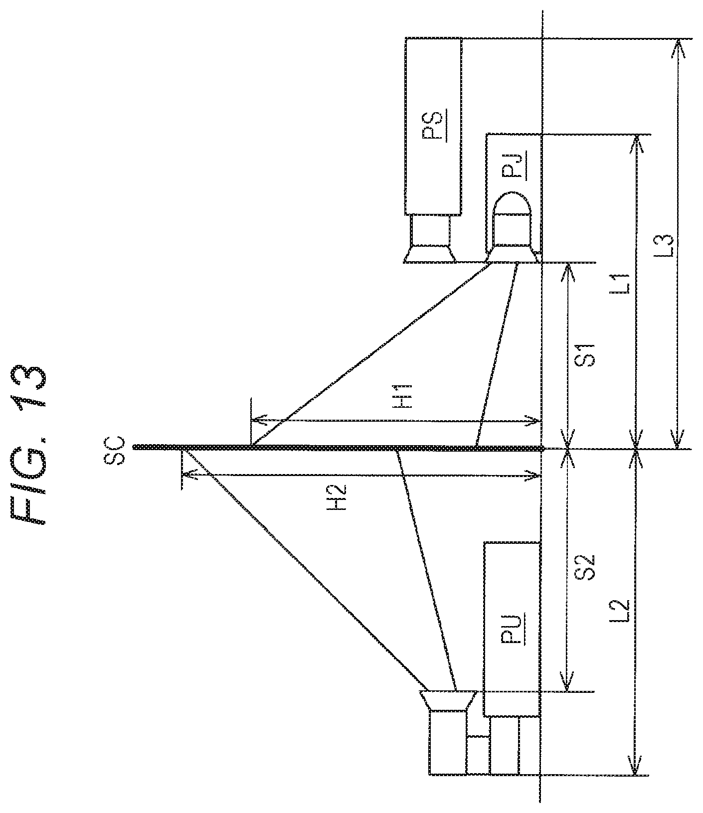
FIG. 13 is a schematic diagram illustrating a projection distance and a projection-direction size of a projection apparatus according to one or more embodiments of the invention.
FIG. 14 is a schematic diagram illustrating one or more embodiments of a projection apparatus.
DETAILED DESCRIPTION
Hereinafter, a projection optical system, a projection apparatus, and the like according to one or more embodiments of the invention will be described with reference to the drawings. However, the scope of the invention is not limited to the disclosed embodiments. The projection optical system according to one or more embodiments of the invention is a projection optical system enlarging and projecting an image displayed on an image display surface, and the projection optical system is a monofocal lens including a first optical system and a second optical system in order from an enlargement side, the second optical system forms an intermediate image of the image between the first optical system and the second optical system, the first optical system enlarges and projects the intermediate image, the first optical system includes a first-A optical system and a first-B optical system in order from the enlargement side and includes a reflecting optical element for bending an light path between the first-A optical system and the first-B optical system.
A projection apparatus according to one or more embodiments of the invention is a projection apparatus including an image display element having an image display surface and a projection optical system enlarging and projecting an image displayed on the image display surface, the projection optical system includes a first optical system and a second optical system in order from the enlargement side, the second optical system forms an intermediate image of the image between the first optical system and the second optical system, the first optical system enlarges and projects the intermediate image, and the first optical system includes a first-A optical system and a first-B optical system in order from the enlargement side and includes a reflecting optical element for bending the light path between the first-A optical system and the first-B optical system.
The "enlargement side" is the direction of the screen surface (enlargement side image surface) on which an enlarged optical image is projected (so-called front side), and the opposite direction is the "reduction side", that is, the direction in which an image display element (for example, a digital micromirror device) displaying an original optical image on the image display surface (reduction side image surface) is to be arranged (so-called rear side).
Herein, the effects of bending the light path will be described. FIG. 13 schematically illustrates three types of projection apparatuses PU, PS, and PJ. In the type of the projection apparatus PU of making a U-turn of the light path, the projection distance is S2, the projection-direction length of the projection apparatus main body is L2, and the height of the upper end of the projection range is H2. In the straight-type projection apparatus PS without bending of the light path, the projection distance is S1, the projection-direction length of the projection apparatus main body is L3, and the height of the upper end of the projection range is H1. In the type of the projection apparatus PJ of bending the light path in the lateral direction (direction parallel to the screen surface SC), the projection distance is S1, the projection-direction length of the projection apparatus main body is L1, and the height of the upper end of the projection range is H1. The magnitude relations of the sizes are S1<S2, L1<L2<L3, and H1<H2.
In the type of the projection apparatus PU of making a U-turn of the light path, in order to prevent the light path from interfering with the projection apparatus main body, the projection position is shifted upward to the height H2. Therefore, the type cannot cope with a case where the ceiling is low, and thus, it is difficult to perform large screen projection. In the straight-type projection apparatus PS without bending of the light path, even if the projection distance S1 is short, since the projection optical system itself becomes longer, the size L3 of the apparatus main body becomes longer in the projection direction. In the type of the projection apparatus PJ in which the light path is bent in the lateral direction, since the light path is bent in the first optical system located to be closer to the enlargement side than to the intermediate image IM1, the size L1 of the apparatus main body is shortened in the projection direction.
In the relay-type projection optical system which forms an intermediate image, it is easy to achieve a wide angle of view capable of performing large screen projection, but the total length of the projection optical system tends to become long. Even in a case where such a projection optical system is used in the projection apparatus, it is possible to shorten the total length in the projection direction of the projection optical system by bending the light path in the first optical system close to the enlargement side. Therefore, similarly to the projection apparatus PJ illustrated in FIG. 13, it is possible to perform large screen projection in a space smaller than those of the projection apparatuses PU and PS in the related art.
In addition, the projection optical system according to one or more embodiments of the invention is configured so that, in the case of the monofocal lens, the following conditional formulas (1) and (2) are satisfied in an infinity in-focus state, and in the case of the zoom lens, the following conditional formulas (1) and (2) are satisfied in an infinity in-focus state in the shortest focal length state: 0.18<Ta/Tw<0.4 (1) 1<fa/|fw|<15 (2)
provided that, Ta is an on-axis distance from the lens surface closest to the enlargement side to the lens surface closest to the reduction side in the first-A optical system, Tw is an on-axis distance from the lens surface closest to the enlargement side to the lens surface closest to the reduction side in the projection optical system, fa is a focal length of the first-A optical system, and fw is a focal length of the entire projection optical system.
The conditional formula (1) defines a ratio of the total length Ta of the first-A optical system to the total length Tw of the projection optical system. If the ratio exceeds the upper limit of the conditional formula (1), the first-A optical system becomes long, and thus, the projection-direction length of the projection optical system becomes long. If the ratio falls below the lower limit of the conditional formula (1), the first-A optical system becomes too short, and thus, the reflecting optical element becomes large, so that cost is increased. In addition, even in a case where the ratio falls down the lower limit of conditional formula (1), if the focal length of the first-A optical system is shortened in order to reduce the size of the reflecting optical element, in particular, distortion tends to occur, so that the image quality of the projected image is deteriorated. Therefore, by satisfying the conditional formula (1), it is possible to shorten the projection-direction length of the projection optical system while suppressing the size of the reflecting optical element and to improve the image quality of the projected image.
The conditional formula (2) defines a ratio of the focal length fa of the first-A optical system to the focal length |fw| of the projection optical system. If the ratio exceeds the upper limit of the conditional formula (2), the focal length of the first-A optical system becomes too long, and if it is attempted to perform projection at a wide angle of view, the reflecting optical element becomes large, so that cost is increased. If the ratio falls below the lower limit of the conditional formula (2), the focal length of the first-A optical system becomes too short, in particular, distortion occurs, so that the image quality of the projected image is deteriorated. Therefore, by satisfying the conditional formula (2), it is possible to shorten the projection-direction length of the projection optical system while suppressing the size of the reflecting optical element and to improve the image quality of the projected image.
In the projection optical system or projection apparatus having the characteristic configuration described above, since the reflecting optical element for bending the light path is configured to be provided inside the first optical system located on the enlargement side of the intermediate image, it is possible to reduce the projection-direction length of the projection optical system, to widen the angle of view of the projection, and to improve the image quality of the projected image without using many optical elements for bending the light path. Therefore, it is possible to realize a projection optical system that can perform large screen projection with high image quality with a short projection distance and can shorten the projection-direction length of the projection apparatus main body at a low cost and a projection apparatus including the projection optical system. Further, since the projection optical system has a configuration that satisfies the conditional formulas (1) and (2), effects thereof are further increased. The conditions for obtaining such effects in a well-balanced manner and achieving higher optical performance, miniaturization, and the like will be described below.
It is preferable to satisfy the following conditional formula (1a). 0.2<Ta/Tw<0.3 (1a)
The conditional formula (1a) defines a further preferable condition range based on the viewpoint and the like among the condition ranges defined by the conditional formula (1). Therefore, preferably, by satisfying the conditional formula (1a), it is possible to further increase the above effects.
It is preferable to satisfy the following conditional formula (2a). 2<fa/|fw|<12 (2a)
The conditional formula (2a) defines a further preferable condition range based on the viewpoint and the like among the condition ranges defined by the conditional formula (2). Therefore, preferably, by satisfying the conditional formula (2a), it is possible to further increase the above effects.
In a case where the projection optical system is a monofocal lens, it is preferable that the projection optical system satisfies the following conditional formula (3) in the infinity in-focus state, and in a case where the projection optical system is a zoom lens, it is preferable that the projection optical system satisfies the following conditional formula (3) in the infinity in-focus state in the shortest focal length state: 0.1<Tb/Tw<0.3 (3)
provided that, Tb is an on-axis distance from the lens surface closest to the enlargement side to the lens surface closest to the reduction side in the first-B optical system, and Tw is an on-axis distance from the lens surface closest to the enlargement side to the lens surface closest to the reduction side in the projection optical system.
The conditional formula (3) defines a ratio of the total length Tb of the first-B optical system to the total length Tw of the projection optical system. In a case where the ratio falls below the lower limit of the conditional formula (3), the first-B optical system is too short, and thus, it difficult to correct off-axis aberration, particularly, curvature of image field, in the first-B optical system. Therefore, in order to obtain good optical performance with a wide angle of view, it is necessary to increase the size of the first-A optical system, so that the size of the entire projection optical system may be greatly increased. The ratio's falling below the upper limit of conditional formula (3) denotes that the first-B optical system becomes longer. In order to cope with this, it is necessary to take a long back focus of the first-A optical system. However, in this case, it is necessary to take a large refractive power of the rear group of the first-A optical system as described later. As a result, the height of the off-axis ray passing near the reflecting optical element becomes high, and thus, it becomes necessary to increase the size of the reflecting optical element, so that cost may be increased. Therefore, it is preferable that the ratio is within the range of the conditional formula (3), and by satisfying the conditional formula (3), it is possible to achieve miniaturization and high performance of the projection optical system in a well-balanced manner while suppressing the size of the reflecting optical element.
It is preferable to satisfy the following conditional formula (3a). 0.15<Tb/Tw<0.25 (3a)
The conditional formula (3a) defines a further preferable condition range based on the viewpoint and the like among the condition ranges defined by the conditional formula (3). Therefore, preferably, by satisfying the conditional formula (3a), it is possible to further increase the above effects.
It is preferable that the first-A optical system includes a negative front group including a negative lens closest to the reduction side and a rear group including only positive lenses in order from the enlargement side. That is, it is preferable that, the first-A optical system is divided into two groups at the interval between the negative lens on the enlargement side and the positive lens on the reduction side, the enlargement side is set as a negative front group, and the reduction side is set as a rear group including only positive lenses. According to this configuration, since the first-A optical system has a retrofocus type refractive power arrangement, it is possible to take a long back focus of the first-A optical system. Therefore, it is possible to easily secure a space for inserting the reflecting optical element into the reduction side of the first-A optical system.
It is preferable that the front group includes one positive lens or less. According to this configuration, in order to realize a wide angle of view, it is possible to reduce the front group that tends to be large in the first-A optical system. Therefore, it is possible to more effectively shorten the projection-direction length of the projection apparatus main body.
It is preferable that the rear group includes three positive lenses. According to this configuration, since the positive refractive power of the rear group can be increased with the minimum number of lenses in the first-A optical system, the space for inserting the reflecting optical element can be made more easily secured without increasing the total length of the first-A optical system.
In a case where the projection optical system is a monofocal lens, it is preferable that the following conditional formula (4) is satisfied in the infinity in-focus state. In a case where the projection optical system is a zoom lens, it is preferable that following conditional formula (4) is satisfied in the infinity in-focus state in the shortest focal length state: -0.4<faf/fa<-0.05 (4)
provided that, faf is a focal length of the front group, and fa is a focal length of the first-A optical system.
The conditional formula (4) defines a refractive power ratio of the front group to the first-A optical system. In a case where the refractive power ratio falls below the lower limit of the conditional formula (4), the refractive power of the front group in the first-A optical system becomes too small, and thus, the front group in the first-A optical system tends to become large. In addition, since the back focus of the first-A optical system is shortened, it is necessary to shorten the first-B optical system in order to secure the space for inserting the reflecting optical element, and thus, it is difficult to reduce the off-axis aberration, particularly, the curvature of image field. In addition, in a case where the refractive power ratio exceeds the upper limit of the conditional formula (4), the refractive power of the front group in the first-A optical system becomes too large, distortion aberration particularly increases in the front group, so that projected image quality may be deteriorated. Therefore, it is preferable that the refractive power ratio is within the range of the conditional formula (4), and by satisfying the conditional formula (4), it is possible to achieve miniaturization and high performance of the projection optical system in a well-balanced manner while suppressing the size of the reflecting optical element.
It is preferable that the first-A optical system includes a first focusing part that moves during focusing, and the first-B optical system or the second optical system includes a second focusing part that moves during focusing. In a case where focusing is performed in the first-A optical system, since the on-axis ray and the off-axis ray are separated from each other, if an error occurs at the in-focus position due to a manufacturing error or the like, aberration deterioration such as curvature of image field tends to occur. In that case, correction is not performed in the first focusing part, the second focusing part is provided inside the first-B optical system or the second optical system so that the on-axis ray and the off-axis ray pass through the positions close to each other, and a manufacturing error or the like is corrected by the second focusing part. Therefore, it is possible to prevent deterioration of off-axis aberration and to maintain high image quality of the projected image. However, in a case where focusing is performed by only the second focusing part without using the first focusing part, in general, the movement amount by focusing also tends to increase in the places where aberration deterioration due to focusing is small, so that the entire projection optical system tends to become large. Therefore, if the focusing is mainly performed by the movement of the first focusing part and the focusing in the second focusing part is limited to fine adjustment, it is possible to effectively prevent the projection optical system from becoming large while maintaining high image quality of the projected image.
It is preferable that the first optical system and the second optical system are on the same optical axis. According to this configuration, a stable image quality can be obtained both in the case of being projected on the upper side of the projection optical system and in the case of being projected on the lower side, and thus, it is possible to increase the number of options for the installation place of the projection optical system.
It is preferable that the second optical system and the entire projection optical system are substantially telecentric on the reduction side. According to this configuration, it is possible to increase the efficiency at the time of capturing the illumination light, and it is possible to prevent deterioration of the image quality.
It is preferable that the projection optical system is a zoom lens that performs zooming by moving a lens group configured as a portion of the second optical system along the optical axis. According to this configuration, the screen size can be adjusted according to the situation, and thus, it is possible to further increase a degree of freedom of installation. In addition, since the interval for bending can be easily maintained by performing zooming with only the second optical system, it is possible to maintain the projection-direction length of the projection apparatus small all the time.
It is preferable that an angle between an optical axis in the light path from the image display surface to the projection optical system and an optical axis in the light path from the projection optical system to the enlargement/projection side is in a range of 60 degrees to 120 degrees. If the angle falls below the lower limit of 60 degrees, the projection apparatus becomes such a type (projection apparatus PU in FIG. 13) that projection is performed by bending the light path back on the projection apparatus main body side. In this case, since it is necessary to perform projection with avoiding the light path from interfering with the projection apparatus main body, projection is performed only at a high position, and thus, it is difficult to perform large screen projection in a room with a low ceiling. If the angle exceeds the upper limit of 120 degrees, the projection apparatus becomes approximate to such a type that bending the light path is not performed (the projection apparatus PS in FIG. 13), the projection-direction length due to the bending of the light path cannot be reduced, and thus, it is difficult to perform large screen projection in a narrow space. Therefore, if the conditions of the angle range are satisfied, it is possible to perform large screen projection with a more compact projection configuration. From such a viewpoint, it is more preferable that an angle between an optical axis in the light path from the image display surface to the projection optical system and an optical axis in the light path from the projection optical system to the enlargement/projection side is in a range of 80 degrees to 100 degrees.
It is preferable that the light path by the reflecting optical element is bent only once. According to this configuration, only one space is required for bending the light path, and it is possible to prevent the projection lens from becoming large.
It is preferable that the reflecting optical element is a plane mirror. According to this configuration, it is possible to minimize the increase in cost due to the reflecting optical element for bending the light path.
It is preferable that the reflecting optical element is a triangular prism, and the light path is bent by using an oblique side of the triangular prism as a reflecting surface. According to this configuration, the space for bending can be buried with glass, and even if only a small air space can be taken, the light path can be bent, and the lens can be prevented from being larger.
Next, specific optical configurations of the projection optical system LN will be described in accordance with one or more embodiments of the invention. FIGS. 1, 2, and 4 are light path diagrams corresponding to the projection optical systems LN in accordance with one or more embodiments of the invention. FIGS. 5, 6, and 8 are optical configuration diagrams (developed diagrams) corresponding to the projection optical systems LN of FIGS. 1, 2, and 4, respectively. In the light path diagrams and the optical configuration diagrams, the lens cross-sectional shape, the lens arrangement, and the like of the projection optical system LN which is a monofocal lens are illustrated in an optical cross section. FIG. 3 is a light path diagram corresponding to the projection optical system LN constituting the third embodiment. FIG. 7 is an optical configuration diagram (developed diagram) corresponding to the projection optical system LN of FIG. 3. In these light path diagrams and optical configuration diagrams, the lens cross-sectional shape, the lens arrangement, and the like of the projection optical system LN, which is a zoom lens are illustrated in optical cross sections at the wide angle end (W) and the telephoto end (T), respectively. In addition, a prism PR (for example, a total internal reflection (TIR) prism, a color separation/combination prism, or the like) and a cover glass CG of the image display element are arranged on the reduction side of the projection optical system LN.
As illustrated in FIGS. 1 to 4, the projection optical system LN in accordance with one or more embodiments of the invention includes a first optical system LN1 (from the first surface to the intermediate image surface IM1) and a second optical system LN2 (from the intermediate image surface IM1 to the last lens surface) in order from the enlargement side, the second optical system LN2 forms the intermediate image IM1 of the image (reduction side image surface) displayed on the image display surface IM2 of the image display element, and the projection optical system is configured to be substantially telecentric on the reduction side where the first optical system LN1 enlarges and projects the intermediate image IM1. The projection optical system LN includes the first optical system LN1 and the second optical system LN2 on the same optical axes AX1 and AX2, and an angle between the optical axis AX2 in the light path from the image display surface IM2 to the projection optical system LN and the optical axis AX1 in the light path from the projection optical system LN1 to the enlargement/projection side is 90 degrees. In addition, the aperture stop ST is located near the center of the second optical system LN2 (for example, according to one or more embodiments, a portion closest to enlargement side in the second-c lens group Gr2c).
The first optical system LN1 includes a first-A optical system LA and a first-B optical system LB in order from the enlargement side and includes a plane mirror M1 or a triangular prism P1 between the first-A optical system LA and the first-B optical system LB as a reflecting optical element for bending the light path. In addition, the first-A optical system LA includes a negative front group LF having a negative lens closest to the reduction side and a rear group LR including only positive lenses in order from the enlargement side (retrofocus type) and, as illustrated in FIG. 5 to FIG. 8, includes a first focusing part F1 or a first focusing part F11 or F12 that moves during focusing. The first-B optical system LB or the second optical system LN2 includes a focusing part F2 that moves during focusing.
FIGS. 1 and 5 show a monofocal lens including thirty lens elements as a whole in accordance with one or more embodiments of the invention. The nineteen lenses on the enlargement side constitute a first optical system LN1 enlarging and projecting the intermediate image IM1, and the eleven lenses on the reduction side constitute a second optical system LN2 forming the intermediate image IM1. Among the lenses of the first optical system LN1, the eight lenses on the enlargement sides constitute a first-A optical system LA, and the eleven lenses on the reduction side constitute a first-B optical system LB. The first optical system LN1 includes a plane mirror M1 as a reflecting optical element for bending the light path between the first-A optical system LA and the first-B optical system LB. According to one or more embodiments, by bending the light path by 90 degrees with the plane mirror M1, the projection-direction length of the projection optical system LN is shortened, so that it is possible to improve a degree of freedom of installation of the projection apparatus PJ (FIG. 13).
FIGS. 1 and 5 show that the five lenses on the reduction side of the first-A optical system LA constitute a first focusing part F1, and the first focusing part is moved to the reduction side as indicated by the arrow m1 with focusing from the infinity to the proximity in accordance with one or more embodiments of the invention. In addition, in a case where the second single lens from the reduction side of the first-B optical system LB is a second focusing part F2, and an error occurs at the focus position of the first focusing part F1 due to a manufacturing error or the like, fine adjustment is performed with the focusing part F2. The arrow m2 indicates the movement to the enlargement side in the focusing from the infinity to the proximity at that time. In Example 1 to be described later, short distance projection up to the projection distance of 1.4 m can be performed by driving of the first focusing part F1, and the movement amount of the first focusing part F1 at that time is 0.5162 mm.
FIGS. 2, 6, 4, and 8 show monofocal lenses including thirty lens elements as a whole in accordance with one or more embodiments of the invention. The nineteen lenses on the enlargement side constitute a first optical system LN1 enlarging and projecting the intermediate image IM1, and the eleven lenses on the reduction side constitute a second optical system LN2 forming the intermediate image IM1. Among the lenses of the first optical system LN1, the eight lenses on the enlargement side constitute a first-A optical system LA, and the eleven lenses on the reduction side constitute a first-B optical system LB. The first optical system LN1 includes a triangular prism P1 with an oblique surface as a reflecting surface of a reflecting optical element for bending the light path between the first-A optical system LA and the first-B optical system LB. According to one or more embodiments of the invention, by bending the light path by 90 degrees with the triangular prism P1, the projection-direction length of the projection optical system LN is shortened, so that it is possible to improve a degree of freedom of installation of the projection apparatus PJ (FIG. 13).
FIGS. 2, 6, 4, and 8 show that the five lenses on the reduction side of the first-A optical system LA constitute a first focusing part F1, and the first focusing part is moved to the reduction side as indicated by the arrow m1 with focusing from the infinity to the proximity in accordance with one or more embodiments of the invention. In addition, in a case where the second single lens from the reduction side of the first-B optical system LB is a second focusing part F2, and an error occurs at the focus position of the first focusing part F1 due to a manufacturing error or the like, fine adjustment is performed with the focusing part F2. The arrow m2 indicates the movement to the enlargement side in the focusing from the infinity to the proximity at that time. In Examples 2 and 4 to be described later, short distance projection up to the projection distance of 1.4 m can be performed by driving the first focusing part F1, and the movement amount of the first focusing part F1 at that time is 0.5669 mm (Example 2), and 0.4364 mm (Example 4).
FIGS. 3 and 7 show a spherical lens system without an aspherical surface including thirty-one lens elements as a whole in accordance with one or more embodiments of the invention. The eighteen lenses on the enlargement side constitute a first optical system LN1 enlarging and projecting the intermediate image IM1, and the thirteen lenses on the reduction side constitute a second optical system LN2 forming the intermediate image IM1. The first optical system LN1 includes a positive first lens group Gr1 as a whole. The second optical system LN2 includes a second-a lens group Gr2a, a second-b lens group Gr2b, a second-c lens group Gr2c, a second-d lens group Gr2d which are positive, positive, positive, and positive in order from the enlargement side. The position of the intermediate image IM1 during zooming is fixed, and zooming is performed only with the second optical system LN2 (five (positive, positive, positive, positive, positive)-group zoom configuration).
The arrows m1x, m2a, m2b, m2c, and m2d in FIG. 1 schematically indicate movement or fixation of the first lens group Gr1, the second-a to second-d lens groups Gr2a to Gr2d in the zooming from the wide angle end (W) to the telephoto end (T), respectively. In other words, the first lens group Gr1 and the second-d lens group Gr2d become fixed groups, and the second-a-to second-c lens groups Gr2a to Gr2c are moving groups, and zooming is configured by allowing the second-a-to second-c lens groups Gr2a to Gr2c to move along the optical axis AX. In zooming from the wide angle end (W) to the telephoto end (T), the second-a lens group Gr2a, the second-b lens group Gr2b, and the second-c lens group Gr2c monotonically move to the enlargement side.
FIGS. 3 and 7 show that among the lenses of the first optical system LN1, the nine lenses on the enlargement side constitute a first-A optical system LA, the nine lenses on the reduction side constitute a first-B optical system LB in accordance with one or more embodiments of the invention. The first optical system LN1 includes a triangular prism P1 with an oblique surface as a reflecting surface of a reflecting optical element for bending the light path between the first-A optical system LA and the first-B optical system LB. According to one or more embodiments, by bending the light path by 90 degrees with the triangular prism P1, the projection-direction length of the projection optical system LN is shortened, so that it is possible to improve a degree of freedom of installation of the projection apparatus PJ (FIG. 13).
FIGS. 3 and 7 show that the four lenses on the reduction side of the first-A optical system LA constitute first focusing parts F11 and F12, and the first focusing part F11 including the one lens on the enlargement side and the first focusing part F12 including the three lenses on the reduction sides independently move to the reduction side as indicated by the arrows m11 and m12, so that focusing from infinity to the proximity is performed in accordance with one or more embodiments of the invention. In addition, in a case where the single lens closest to the reduction side of the second optical system LN2 is a second focusing part F2, and an error occurs at the focus position of the first focusing part F1 due to a manufacturing error or the like, fine adjustment is performed with the second focusing part F2. The arrow m2 indicates the movement to the enlargement side in the focusing from the infinity to the proximity at that time. In Example 3 to be described later, short distance projection up to the projection distance of 2.8 m can be performed by driving the first focusing part F1. The movement amount of the first focusing part F11 on the enlargement side at that time is 0.2275 mm, and the movement amount of the first focusing part F12 on the reduction side is 0.2781 mm.
As described above, according to one or more embodiments of the invention, the projection optical system LN is configured to moves the moving group relative to the image display surface IM2 to change the interval between the groups on the axis, so that the zooming from the wide angle end (W) to the telephoto end (T) is performed. Since the zoom positions of the first lens group Gr1 and the second-d lens group Gr2d are fixed, there is no change in the total length of the optical system due to the zooming, and the number of moving components is reduced, so that a zooming mechanism can be simplified. In addition, the zoom positions of the prism PR and the cover glass CG located on the reduction side of the second-d lens group Gr2d are also fixed.
In the relay-type projection optical system forming the intermediate image IM1, since the lens system tends to be long, a plane mirror M1 or a triangular prism P1 is arranged in the first optical system LN1 similarly to the embodiments, so that the projection optical system LN becomes an L-shaped bending optical system. Therefore, it is possible to effectively achieve compactification of the entire projection optical system LN. If the total length and the focal length of the first-A optical system LA are set that the conditional formulas (1) and (2) are satisfied, it is possible to shorten the projection-direction length of the projection optical system LN while suppressing the size of the reflecting optical element, and it is possible to improve the image quality of the projected image IM2.
Next, one or more embodiments of a projection apparatus including the projection optical system LN will be described. FIG. 14 illustrates a schematic configuration example of the projection apparatus PJ. The projection apparatus PJ includes a light source 1, an illumination optical system 2, a reflecting mirror 3, a prism PR, an image display element (image forming element) 4, a controller 5, an actuator 6, a projection optical system LN, and the like. The controller 5 performs the overall control of the projection apparatus PJ. The image display element 4 is an image modulation element (for example, a digital micromirror device) modulating light to generate an image and has an image display surface IM2 displaying an image. A cover glass CG is provided on the image display surface IM2.
Light emitted from a light source 1 (for example, a white light source such as a xenon lamp or a laser light source) is guided to the image display element 4 by the illumination optical system 2, the reflecting mirror 3, and the prism PR, and image light is formed in the image display element 4. The prism PR is configured with, for example, a TIR prism (a color separation/combination prism or the like) and separates illumination light and projection light. The image light formed by the image display element 4 is enlarged and projected toward the screen surface SC by the projection optical system LN. That is, the image IM2 displayed on the image display element 4 becomes an intermediate image IM1 in the second optical system LN2, and after that, the image is enlarged and projected on the screen surface SC by the first optical system LN1.
As described above, the projection apparatus PJ includes the image display element 4 displaying an image, the light source 1, the illumination optical system 2 guiding light from the light source 1 to the image display element 4, and the projection optical system LN enlarging and projecting the image displayed on the image display element 4 onto the screen surface SC. However, the projection apparatus to which the projection optical system LN can be applied is not limited thereto. For example, if an image display element displaying an image by light emission of the image display surface IM2 itself is used, illumination can be made unnecessary, and in that case, the projection apparatus can be configured without using the light source 1 or the illumination optical system 2.
An actuator 6 for movement to the enlargement side or the reduction side along each optical axis AX is connected to the lens group that moves for zooming and focusing in the projection optical system LN. A controller 5 for controlling movement of the moving group is connected to the actuator 6. In addition, the lens group may be manually moved without using the controller 5 and the actuator 6.
EXAMPLES
Hereinafter, the configurations and the like of the projection optical system according to embodiments of the invention will be described in more detail with reference to construction data and the like of Examples. Examples 1 to 4 (EX 1 to EX 4) described herein are numerical examples corresponding to one or more embodiments described above. Light path diagrams and optical configuration diagrams (FIGS. 5 to 8) (FIGS. 1 to 4) illustrating one or more embodiments illustrate cross-section shapes of lenses, lens arrangement, and the like of corresponding Examples 1 to 4, respectively.
In the construction data of each Example, as surface data, from the left column, a surface number i, a radius of curvature r (mm) in a paraxial position, an on-axis surface interval d (mm), a refractive index nd for d line (wavelength 587.56 nm), and an Abbe number vd for d line are listed. In addition, SC denotes a screen surface, ST denotes an aperture stop, IM1 denotes an intermediate image surface, and IM2 denotes an image display surface.
A Surface having a surface number i attached with * is an aspheric surface, and the surface shape thereof is defined by the following formula (AS) using a local orthogonal coordinate system (x, y, z) having a surface vertex as the origin. As aspherical data, aspherical coefficients and the like are listed. In addition, with respect to the aspherical data of each Example, the coefficients of the terms having no marks are 0, and e-n=.times.10.sup.-n for all the data. z=(ch.sup.2)/[1+ {1-(1+K)c.sup.2h.sup.2}]+.SIGMA.(Ajh.sup.j) (AS)
provided that, h is a height (h.sup.2=x.sup.2+y.sup.2) in a direction perpendicular to the z axis (optical axis AX), z is a Sag amount in the direction of the optical axis AX (with reference to a vertex of the surface) at the position of the height h, c is a curvature at the vertex of the surface (a reciprocal of radius of curvature r), K is a conical constant, and Aj is a j-th order aspherical coefficient.
As various data of Examples 1, 2, and 4, focal lengths (Fl, mm), F numbers (Fno), half angle of view (.omega., .degree.), image heights (ymax, mm), total lens lengths (TL, mm), and back focuses (BF, mm) are listed. In addition, as various data of Example 3, zoom ratios are listed, and with respect to focal length states W (Wide), M (Middle), and T (Tele), the focal lengths (Fl, mm) of the entire system, F numbers (Fno.), half angle of view (.omega., .degree.), image heights (ymax, mm), total lens lengths (TL, mm), back focuses (BF, mm), and variable surface intervals (di, i: surface number, mm) are listed, and as zoom lens group data, and focal lengths mm) of each lens group are listed. In addition, with respect to the back focuses BF, the distance from the last lens surface to the paraxial image surface is expressed by an air conversion length, and the total length TL of the lens is obtained by adding the back focus BF to the distance Tw from the foremost lens surface to the last lens surface. The image height ymax corresponds to a half of the diagonal length of the image display surface IM2. The TL-BF at the wide angle end (W) corresponds to the on-axis distance Tw.
Table 1 lists values corresponding to conditional formulas, data related to the conditional formulas, and the like for each Example. In a case where the projection optical system LN is a single focus lens, the data related to the conditional formula are data in the infinity in-focus state. In a case where the projection optical system LN is a zoom lens, the data related to the conditional formula are data in the infinity in-focus state in the shortest focal length state. The projection-direction length L1 of only the projection optical system LN is data in the closest in-focus state.
The data are, for example, the on-axis distance (Ta, mm) from the lens surface closest to the enlargement side to the lens surface closest to the reduction side in the first-A optical system LA, the on-axis distance (Tb, mm) from the lens surface closest to the enlargement side to the lens surface closest to the reduction side in the first-B optical system LB, the on-axis distance (Tw, mm) from the lens surface closest to the enlargement side to the lens surface closest to the reduction side in the projection optical system LN, the focal length (fa, mm) of the first-A optical system LA, the focal length (fb, mm) of the first-B optical system LB, the focal length (fw, mm) of the entire projection optical system LN, the focal length (faf, mm) of the front group LF, the focal length (far, mm) of the rear group LR, and the projection-direction length (L1, mm, at the time of the closest in-focus) of only the projection optical system LN.
FIGS. 9A to 9C, FIGS. 10A to 10C, and FIGS. 12A to 12C are aberration diagrams (longitudinal aberration diagrams in the infinity in-focus state) corresponding to Examples 1, 2, and 4 (EX1, 2, and 4). FIGS. 9A, 10A, and 12A are spherical aberration diagrams, FIGS. 9B, 10B, and 12B are astigmatism diagrams, and FIGS. 9C, 10C, and 12C are distortion aberration diagrams. FIGS. 11A to 11I are aberration diagrams (longitudinal aberration diagrams in the infinity in-focus state) corresponding to Example 3 (EX3). FIGS. 11A to 11C illustrate various aberrations at the wide angle end W, FIGS. 11D to 11F illustrate various aberrations at the intermediate focal length state M, and FIGS. 11G to 11I illustrate various aberrations at the telephoto end T. In addition, FIGS. 11A, 11D, and 11G are spherical aberration diagrams, FIGS. 11B, 11E, and 11H are astigmatism diagrams, and FIGS. 11C, 11F, and 11I are distortion aberration diagrams.
In the spherical aberration diagram, the spherical aberration amount for d line (wavelength 587.56 nm) indicated by the solid line, the spherical aberration amount for C line (wavelength 656.28 nm) indicated by the one-dot dashed line and, the spherical aberration amount for g line (wavelength 435.84 nm) indicated by the broken line are represented by the respective shift amounts (unit: mm) in the direction of the optical axis AX from the paraxial image surface, and the vertical axis represents values (that is, relative pupil heights) obtained by normalizing incident heights on the pupil by the maximum height. In the astigmatism diagram, the broken line T represents a tangential image surface with respect to the d line, the solid line S represents a sagittal image surface with respect to the d line in terms of a shift amount (unit: mm) in the direction of the optical axis AX from the paraxial image surface, and the vertical axis represents an image height (IMG HT, unit: mm). In the distortion aberration diagram, the horizontal axis represents distortion (unit: %) with respect to the d line, and the vertical axis represents an image height (IMG HT, unit: mm).
In addition, in a case where each embodiment is used as the projection apparatus (for example, liquid crystal projection apparatus) PJ as the projection optical system LN (FIG. 14), originally, the screen surface (projected surface) SC is an image surface, and the image display surface IM2 (for example, liquid crystal panel surface) is an object plane. However, each embodiment is configured as a reduction system in terms of optical design, and the screen surface SC is assumed to be an object surface (object), and optical performance is evaluated with an image display surface (reduction side image side) IM2 corresponding to the image surface (image). As can be seen from the obtained optical performance, the projection optical system LN of each embodiment can be appropriately used not only as a projection lens for a projection apparatus but also as an imaging lens for an imaging apparatus (for example, a video camera and a digital camera).
Example 1
TABLE-US-00001 Unit: mm Surface data i r d nd vd object (SC) infinity infinity 1 110.211 7.900 1.70154 41.15 2 61.662 14.014 3 91.619 5.700 1.83400 37.34 4 43.595 13.724 5* 178.863 9.000 1.83404 37.30 6 36.274 17.627 7 1408.262 2.900 1.83400 37.34 8 47.851 19.837 9 -32.235 3.088 1.84666 23.78 10 -152.555 9.253 11 -62.063 9.318 1.91082 35.25 12 -48.672 0.954 13 -277.852 14.450 1.90366 31.31 14 -66.419 0.386 15 143.440 8.354 1.83400 37.34 16 4952.704 88.748 17 216.730 1.800 1.60342 38.01 18 38.511 3.315 19 50.863 8.215 1.43700 95.10 20 -71.433 0.300 21 52.185 7.106 1.43700 95.10 22 -254.535 6.549 23 83.868 2.229 1.80610 33.27 24 32.475 5.924 25 51.515 13.472 1.43700 95.10 26 -34.405 0.821 27 -44.313 2.400 1.80610 33.27 28 -126.151 0.457 29 51.144 13.192 1.43700 95.10 30 -41.124 1.018 31 -47.580 2.463 1.62004 36.30 32 32.480 10.724 33 208.808 8.688 1.80860 40.42 34* -43.010 3.000 35 101.251 6.240 1.85478 24.80 36 -463.622 3.000 37 55.234 5.912 1.80518 25.46 38 138.546 7.721 39 (IM1) infinity 21.016 40 -33.329 4.636 1.51680 64.20 41 -25.612 2.512 42 -24.532 2.000 1.80610 33.27 43 204.292 8.796 44 -42.719 7.130 1.91082 35.25 45 -28.775 11.631 46 -4887.657 10.348 1.58913 61.25 47 -43.443 53.755 48 (ST) infinity 13.131 49 -3424.192 5.460 1.43700 95.10 50 -44.090 10.337 51 -30.823 1.800 1.80610 33.27 52 89.752 1.492 53 53.171 9.361 1.43700 95.10 54 -37.488 0.300 55 106.711 6.776 1.59282 68.62 56 -64.780 11.881 57 -28.070 2.200 1.80610 40.73 58 211.052 3.078 59 1371.941 13.642 1.55032 75.50 60 -34.666 1.216 61 -3409.579 8.075 1.80518 25.46 62 -71.309 16.128 63 infinity 85.000 1.51680 64.20 64 infinity 4.000 65 infinity 3.000 1.48749 70.44 66 infinity 1.500 image (IM2) infinity Aspherical data i K A4 A6 A8 5 5.9118e+000 3.0980e-006 -1.0995e-009 4.9448e-013 i A10 A12 A14 A16 5 -1.7938e-017 0.0000e+000 0.0000e+000 0.0000e+000 i K A4 A6 A8 34 0.0000e+000 1.8692e-005 -2.9757e-008 4.1597e-011 i A10 A12 A14 A16 34 -4.1096e-014 1.7008e-017 0.0000e+000 0.0000e+000 Various data Fl -7.967 Fno. 2.494 .omega. 66.360 ymax 18.200 TL 630.062 BF 79.690
Example 2
TABLE-US-00002 Unit: mm Surface data i r d nd vd object (SC) infinity infinity 1 127.246 7.900 1.70154 41.15 2 58.561 11.368 3 76.058 5.700 1.83400 37.34 4 37.299 13.571 5* 111.747 9.000 1.83404 37.30 6 32.610 17.943 7 337.299 2.900 1.83400 37.34 8 49.585 16.900 9 -31.194 3.000 1.84666 23.78 10 -172.867 9.900 11 -69.138 9.702 1.91082 35.25 12 -49.543 1.558 13 -293.390 14.071 1.90366 31.31 14 -65.725 0.300 15 91.438 8.758 1.83400 37.34 16 273.355 40.470 17 infinity 50.000 1.51680 64.20 18 infinity 2.804 19 -136.156 1.800 1.60342 38.01 20 38.009 2.465 21 51.865 9.041 1.43700 95.10 22 -55.273 0.300 23 43.509 9.987 1.43700 95.10 24 -112.447 1.315 25 88.298 2.200 1.80610 33.27 26 32.146 6.853 27 55.875 15.616 1.43700 95.10 28 -31.575 0.329 29 -35.898 2.300 1.80610 33.27 30 -70.078 0.300 31 42.131 13.558 1.43700 95.10 32 -69.422 1.448 33 -147.625 2.400 1.62004 36.30 34 28.974 11.077 35 -110.325 4.931 1.80860 40.42 36* -41.146 3.000 37 82.753 6.520 1.85478 24.80 38 -1029.192 3.000 39 45.402 7.079 1.80518 25.46 40 123.932 8.023 41 (IM1) infinity 21.319 42 -33.915 5.835 1.51680 64.20 43 -26.220 1.810 44 -25.677 1.900 1.80610 33.27 45 352.708 8.385 46 -39.914 8.492 1.91082 35.25 47 -29.045 14.298 48 854.653 10.443 1.58913 61.25 49 -48.613 59.995 50 (ST) infinity 13.100 51 356.232 5.631 1.43700 95.10 52 -44.256 2.058 53 -41.295 1.700 1.80610 33.27 54 64.873 0.726 55 40.765 8.585 1.43700 95.10 56 -44.784 4.602 57 76.791 5.395 1.59282 68.62 58 -228.176 10.304 59 -27.272 2.239 1.80610 40.73 60 341.173 2.892 61 -702.129 12.707 1.55032 75.50 62 -33.767 0.300 63 363.481 8.397 1.80518 25.46 64 -78.776 16.000 65 infinity 85.000 1.51680 64.20 66 infinity 4.000 67 infinity 3.000 1.48749 70.44 68 infinity 1.500 image (IM2) infinity Aspherical data i K A4 A6 A8 5 8.1195e+000 3.2138e-006 -1.1472e-009 5.9904e-013 i A10 A12 A14 A16 5 3.5475e-017 0.0000e+000 0.0000e+000 0.0000e+000 i K A4 A6 A8 36 0.0000e+000 1.4756e-005 -1.8601e-008 2.8475e-011 i A10 A12 A14 A16 36 -3.3065e-014 1.7008e-017 0.0000e+000 0.0000e+000 Various data Fl -7.967 Fno. 2.500 .omega. 66.359 ymax 18.200 TL 630.056 BF 79.556
Example 3
TABLE-US-00003 Unit: mm Surface data i r d nd vd object (SC) infinity infinity 1 103.168 7.900 1.69680 55.46 2 70.921 11.157 3 85.761 6.600 1.80518 25.46 4 60.220 14.259 5 85.647 16.232 1.83400 37.34 6 292.247 2.192 7 51.982 3.900 1.90366 31.31 8 28.000 10.025 9 60.655 2.900 1.84666 23.78 10 25.616 16.427 11 -32.708 1.900 1.91082 35.25 12 243.416 13.954 13 -77.913 5.785 1.72916 54.67 14 -46.983 0.300 15 3061.669 10.903 1.43700 95.10 16 -41.355 11.379 17 79.183 6.988 1.78472 25.72 18 -217.019 8.411 19 infinity 40.000 1.51680 64.20 20 infinity 5.588 21 -36.083 2.000 1.90366 31.31 22 96.444 3.837 23 115.687 9.233 1.43700 95.10 24 -31.913 0.300 25 49.975 9.487 1.43700 95.10 26 -89.701 1.738 27 190.681 2.778 1.90366 31.31 28 41.106 2.094 29 38.798 11.968 1.43700 95.10 30 -80.011 0.300 31 69.463 7.994 1.49700 81.61 32 -131.816 6.386 33 -38.983 2.700 1.60342 38.01 34 50.024 13.890 35 125.932 10.450 1.80518 25.46 36 -102.854 30.797 37 60.912 7.290 1.80809 22.76 38 94.527 8.948 39 (IM1) infinity variable 40 -166.927 7.706 1.90366 31.31 41 -67.220 28.584 42 -42.827 2.500 1.65844 50.85 43 -144.938 3.817 44 -65.266 6.607 1.69680 55.46 45 -40.277 variable 46 947.335 4.924 1.91082 35.25 47 -95.757 11.662 48 -43.641 1.900 1.80518 25.46 49 -80.170 1.478 50 -143.575 4.667 1.48749 70.44 51 -43.655 variable 52 (ST) infinity 8.568 53 -38.795 1.500 1.72916 54.67 54 68.421 12.003 55 62.681 8.842 1.43700 95.10 56 -44.175 2.395 57 462.303 7.386 1.49700 81.61 58 -54.545 8.797 59 -33.648 2.200 1.69680 55.46 60 112.375 3.781 61 440.881 8.115 1.49700 81.61 62 -55.250 0.712 63 465.977 9.862 1.49700 81.61 64 -51.998 variable 65 111.804 7.483 1.49700 81.61 66 -510.777 15.376 67 infinity 85.000 1.51680 64.20 68 infinity 5.000 69 infinity 3.000 1.48749 70.44 70 infinity 1.500 image (IM2) infinity Various data Zoom ratio 1.31 Wide (W) Middle (M) Tele (T) Fl -13.898 -16.035 -18.172 Fno. 2.444 2.500 2.565 .omega. 50.349 46.318 42.729 ymax 16.700 16.700 16.700 TL 658.124 658.129 658.124 BF 79.953 79.958 79.953 d39 58.812 54.091 52.248 d45 27.797 15.546 2.000 d51 3.083 11.600 17.275 d64 4.000 12.455 22.169 Zoom lens group data Group (Surface i) Focal length Gr1 (1-39) 24.536 Gr2a (40-45) 176.362 Gr2b (46-51) 100.417 Gr2c (52-64) 132.500 Gr2d (65-70) 185.299
Example 4
TABLE-US-00004 Unit: mm Surface data i r d nd vd object (SC) infinity infinity 1 89.112 7.900 1.70154 41.15 2 43.804 29.561 3 130.651 5.700 1.83400 37.34 4 39.769 8.976 5* 125.558 9.000 1.83404 37.30 6 36.363 15.989 7 279.730 2.900 1.83400 37.34 8 52.127 18.257 9 -32.080 3.100 1.84666 23.78 10 -141.499 8.808 11 -68.384 10.115 1.91082 35.25 12 -51.302 0.475 13 -246.942 16.259 1.90366 31.31 14 -68.128 4.015 15 92.259 13.086 1.83400 37.34 16 541.440 39.548 17 infinity 50.000 1.51680 64.20 18 infinity 3.733 19 -73.815 1.800 1.60342 38.01 20 41.160 2.464 21 57.269 8.836 1.43700 95.10 22 -52.700 0.300 23 42.870 10.194 1.43700 95.10 24 -108.726 0.300 25 64.778 2.200 1.80610 33.27 26 29.789 2.717 27 35.096 14.696 1.43700 95.10 28 -38.697 0.720 29 -46.455 2.300 1.80610 33.27 30 -122.121 0.300 31 42.960 11.002 1.43700 95.10 32 -60.090 1.029 33 -78.059 2.400 1.62004 36.30 34 26.796 12.039 35 -41.411 5.038 1.80860 40.42 36* -25.425 3.000 37 178.536 6.668 1.85478 24.80 38 -102.167 3.000 39 39.256 7.007 1.80518 25.46 40 91.921 8.403 41 (IM1) infinity 21.199 42 -30.878 4.677 1.51680 64.20 43 -24.301 2.304 44 -22.518 1.900 1.80610 33.27 45 1605.845 6.495 46 -41.742 7.695 1.91082 35.25 47 -27.309 9.364 48 1508.773 10.612 1.58913 61.25 49 -42.530 53.300 50 (ST) infinity 13.100 51 234.415 5.693 1.43700 95.10 52 -45.001 2.049 53 -42.064 1.700 1.80610 33.27 54 58.563 1.078 55 42.918 8.945 1.43700 95.10 56 -38.922 2.849 57 83.030 5.650 1.59282 68.62 58 -185.037 10.742 59 -26.025 2.200 1.80610 40.73 60 1271.718 2.931 61 -343.902 13.374 1.55032 75.50 62 -32.154 0.300 63 4109.328 8.508 1.80518 25.46 64 -72.118 16.000 65 infinity 85.000 1.51680 64.20 66 infinity 4.000 67 infinity 3.000 1.48749 70.44 68 infinity 1.500 image (IM2) infinity Aspherical data i K A4 A6 A8 5 1.0976e+001 4.2149e-006 -1.4362e-009 8.7441e-013 i A10 A12 A14 A16 5 8.8780e-017 0.0000e+000 0.0000e+000 0.0000e+000 i K A4 A6 A8 36 0.0000e+000 1.9713e-005 -1.0138e-008 2.4708e-011 i A10 A12 A14 A16 36 -1.5376e-014 1.7008e-017 0.0000e+000 0.0000e+000 Various data Fl -7.967 Fno. 2.500 .omega. 66.358 ymax 18.200 TL 630.056 BF 79.556
TABLE-US-00005 TABLE 1 Values corresponding to conditional formula and the like Example 1 Example 2 Example 3 Example 4 (1) Ta/Tw 0.25 0.24 0.25 0.28 (2) fa/|fw| 8.56 5.28 2.15 4.10 (3) Tb/Tw 0.19 0.19 0.21 0.18 (4) faf/fa -0.10 -0.16 -0.38 -0.20 Ta 136.506 132.572 142.802 154.140 Tb 106.824 105.519 123.243 98.010 Tw 550.372 550.500 578.171 550.500 fa 68.192 42.069 29.867 32.695 fb 40.912 36.972 72.525 33.471 fw -7.967 -7.967 -13.898 -7.967 faf -7.067 -6.894 -11.398 -6.396 far 45.164 41.627 36.546 42.676 L1 1622.3 1624.8 3001.1 1646.2
Although the disclosure has been described with respect to only a limited number of embodiments, those skilled in the art, having benefit of this disclosure, will appreciate that various other embodiments may be devised without departing from the scope of the present invention. Accordingly, the scope of the invention should be limited only by the attached claims.
* * * * *
D00000
D00001
D00002
D00003
D00004
D00005
D00006
D00007
D00008
D00009
D00010
D00011
D00012
D00013
D00014

D00015
D00016

XML
uspto.report is an independent third-party trademark research tool that is not affiliated, endorsed, or sponsored by the United States Patent and Trademark Office (USPTO) or any other governmental organization. The information provided by uspto.report is based on publicly available data at the time of writing and is intended for informational purposes only.
While we strive to provide accurate and up-to-date information, we do not guarantee the accuracy, completeness, reliability, or suitability of the information displayed on this site. The use of this site is at your own risk. Any reliance you place on such information is therefore strictly at your own risk.
All official trademark data, including owner information, should be verified by visiting the official USPTO website at www.uspto.gov. This site is not intended to replace professional legal advice and should not be used as a substitute for consulting with a legal professional who is knowledgeable about trademark law.