Conductive detonating cord for perforating gun
Preiss , et al. November 24, 2
U.S. patent number 10,845,177 [Application Number 16/503,839] was granted by the patent office on 2020-11-24 for conductive detonating cord for perforating gun. This patent grant is currently assigned to DynaEnergetics Europe GmbH. The grantee listed for this patent is DynaEnergetics GmbH & Co. KG. Invention is credited to Christian Eitschberger, Liam McNelis, Frank Haron Preiss, Thilo Scharf, Bernhard Scharfenort.


| United States Patent | 10,845,177 |
| Preiss , et al. | November 24, 2020 |
Conductive detonating cord for perforating gun
Abstract
A detonating cord for using in a perforating gun includes an explosive layer and an electrically conductive layer extending around the explosive layer. The electrically conductive layer is configured to relay a communication signal along a length of the detonating cord. In an embodiment, a protective jacket extends around the electrically conductive layer of the detonating cord. The detonating cord may be assembled in a perforating gun to relay a communication signal from a top connector to a bottom connector of the perforating gun, and to propagate a detonating explosive stimulus along its length to initiate shaped charges of the perforating gun. A plurality of perforating guns, including the detonating cord, may be connected in series, with the detonating cord of a first perforating gun in communication with the detonating cord of a second perforating gun.
| Inventors: | Preiss; Frank Haron (Bonn, DE), McNelis; Liam (Bonn, DE), Scharf; Thilo (Letterkenny, IE), Eitschberger; Christian (Munich, DE), Scharfenort; Bernhard (Troisdorf, DE) | ||||||||||
|---|---|---|---|---|---|---|---|---|---|---|---|
| Applicant: |
|
||||||||||
| Assignee: | DynaEnergetics Europe GmbH
(Troisdorf, DE) |
||||||||||
| Family ID: | 1000005202047 | ||||||||||
| Appl. No.: | 16/503,839 | ||||||||||
| Filed: | July 5, 2019 |
Prior Publication Data
| Document Identifier | Publication Date | |
|---|---|---|
| US 20190376775 A1 | Dec 12, 2019 | |
Related U.S. Patent Documents
| Application Number | Filing Date | Patent Number | Issue Date | ||
|---|---|---|---|---|---|
| 16152933 | Oct 5, 2018 | 10386168 | |||
| 62683083 | Jun 11, 2018 | ||||
| Current U.S. Class: | 1/1 |
| Current CPC Class: | F42C 19/12 (20130101); E21B 43/119 (20130101); E21B 43/1185 (20130101); F42D 1/043 (20130101); F42B 1/02 (20130101); F42D 1/055 (20130101) |
| Current International Class: | F42D 1/055 (20060101); E21B 43/119 (20060101); E21B 43/1185 (20060101); F42B 1/02 (20060101); F42D 1/04 (20060101); F42C 19/12 (20060101) |
| Field of Search: | ;102/317,322,200,202.9,202.11,217,275.1,275.2,275.4-275.8,275.12 |
References Cited [Referenced By]
U.S. Patent Documents
| 2216359 | October 1940 | Spencer |
| 2228873 | January 1941 | Hardt et al. |
| 2358466 | September 1944 | Miller |
| 2418486 | April 1947 | Smylie |
| 2439394 | April 1948 | Lanzalotti et al. |
| 2598651 | May 1952 | Spencer |
| 2889775 | June 1959 | Owen |
| 2906339 | September 1959 | Griffin |
| 2982210 | May 1961 | Andrew et al. |
| 3013491 | December 1961 | Poulter |
| 3125024 | March 1964 | Hicks et al. |
| 3158680 | November 1964 | Lovitt et al. |
| 3170400 | February 1965 | Nelson |
| 3246707 | April 1966 | Bell |
| 3357355 | December 1967 | Roush |
| 3374735 | March 1968 | Moore |
| 3504723 | April 1970 | Cushman et al. |
| 3565188 | February 1971 | Hakala |
| 3731626 | May 1973 | Grayson |
| 3859921 | January 1975 | Stephenson |
| 3892455 | July 1975 | Sotolongo |
| 4007790 | February 1977 | Henning |
| 4007796 | February 1977 | Boop |
| 4024817 | May 1977 | Calder, Jr. |
| 4058061 | November 1977 | Mansur, Jr. et al. |
| 4080902 | March 1978 | Goddard |
| 4100978 | July 1978 | Boop |
| 4107453 | August 1978 | Erixon |
| 4132171 | January 1979 | Pawlak et al. |
| 4140188 | February 1979 | Vann |
| 4182216 | January 1980 | DeCaro |
| 4191265 | March 1980 | Bosse-Platiere |
| 4220087 | September 1980 | Posson |
| 4266613 | May 1981 | Boop |
| 4290486 | September 1981 | Regalbuto |
| 4312273 | January 1982 | Camp |
| 4346954 | August 1982 | Appling |
| 4411491 | October 1983 | Larkin et al. |
| 4455941 | June 1984 | Walker et al. |
| 4491185 | January 1985 | McClure |
| 4496008 | January 1985 | Pottier et al. |
| 4523650 | June 1985 | Sehnert et al. |
| 4534423 | August 1985 | Regalbuto |
| 4574892 | March 1986 | Grigar et al. |
| 4598775 | July 1986 | Vann et al. |
| 4609057 | September 1986 | Walker et al. |
| 4621396 | November 1986 | Walker et al. |
| 4640370 | February 1987 | Wetzel |
| 4650009 | March 1987 | McClure et al. |
| 4657089 | April 1987 | Stout |
| 4660910 | April 1987 | Sharp et al. |
| 4744424 | May 1988 | Lendermon et al. |
| 4747201 | May 1988 | Donovan et al. |
| 4753170 | June 1988 | Regalbuto et al. |
| 4762067 | August 1988 | Barker et al. |
| 4776393 | October 1988 | Forehand et al. |
| 4790383 | December 1988 | Savage et al. |
| 4800815 | January 1989 | Appledorn et al. |
| 4850438 | July 1989 | Regalbuto |
| 4889183 | December 1989 | Sommers et al. |
| 4998478 | March 1991 | Beck |
| 5001981 | March 1991 | Shaw |
| 5010821 | April 1991 | Blain |
| 5027708 | July 1991 | Gonzalez |
| 5052489 | October 1991 | Carisella et al. |
| 5060573 | October 1991 | Montgomery et al. |
| 5083929 | January 1992 | Dalton |
| 5088413 | February 1992 | Huber |
| 5105742 | April 1992 | Sumner |
| 5159145 | October 1992 | Carisella et al. |
| 5159146 | October 1992 | Carisella et al. |
| 5223664 | June 1993 | Rogers |
| 5241891 | September 1993 | Hayes et al. |
| 5322019 | June 1994 | Hyland |
| 5347929 | September 1994 | Lerche et al. |
| 5392851 | February 1995 | Arend |
| 5392860 | February 1995 | Ross |
| 5436791 | July 1995 | Turano et al. |
| 5529509 | June 1996 | Hayes et al. |
| 5540154 | July 1996 | Wilcox |
| 5558531 | September 1996 | Ikeda et al. |
| 5603384 | February 1997 | Bethel et al. |
| 5648635 | July 1997 | Lussier et al. |
| 5703319 | December 1997 | Fritz et al. |
| 5759056 | June 1998 | Costello et al. |
| 5765962 | June 1998 | Cornell et al. |
| 5769661 | June 1998 | Nealis |
| 5775426 | July 1998 | Snider et al. |
| 5785130 | July 1998 | Wesson et al. |
| 5816343 | October 1998 | Markel et al. |
| 5837924 | November 1998 | Austin |
| 5837925 | November 1998 | Nice |
| 5992289 | November 1999 | George et al. |
| 6006833 | December 1999 | Burleson et al. |
| 6012525 | January 2000 | Burleson et al. |
| 6085659 | July 2000 | Beukes et al. |
| 6112666 | September 2000 | Murray et al. |
| 6297447 | October 2001 | Burnett et al. |
| 6298915 | October 2001 | George |
| 6305287 | October 2001 | Capers et al. |
| 6354374 | March 2002 | Edwards et al. |
| 6386108 | May 2002 | Brooks et al. |
| 6408758 | June 2002 | Duguet |
| 6412415 | July 2002 | Kothari et al. |
| 6418853 | July 2002 | Duguet et al. |
| 6439121 | August 2002 | Gillingham |
| 6467415 | October 2002 | Menzel et al. |
| 6487973 | December 2002 | Gilbert, Jr. et al. |
| 6497285 | December 2002 | Walker |
| 6508176 | January 2003 | Badger et al. |
| 6651747 | November 2003 | Chen et al. |
| 6739265 | May 2004 | Badger et al. |
| 6742602 | June 2004 | Trotechaud |
| 6752083 | June 2004 | Lerche et al. |
| 6772868 | August 2004 | Warner |
| 6843317 | January 2005 | Mackenzie |
| 6851471 | February 2005 | Barlow et al. |
| 6976857 | December 2005 | Shukla et al. |
| 7107908 | September 2006 | Forman et al. |
| 7182611 | February 2007 | Borden et al. |
| 7193527 | March 2007 | Hall |
| 7237626 | July 2007 | Gurjar et al. |
| 7278491 | October 2007 | Scott |
| 7306038 | December 2007 | Challacombe |
| 7347278 | March 2008 | Lerche et al. |
| 7347279 | March 2008 | Li et al. |
| 7350448 | April 2008 | Bell et al. |
| 7357083 | April 2008 | Takahara et al. |
| 7404725 | July 2008 | Hall et al. |
| 7441601 | October 2008 | George et al. |
| 7481662 | January 2009 | Rehrig |
| 7553078 | June 2009 | Hanzawa et al. |
| 7568429 | August 2009 | Hummel et al. |
| 7640857 | January 2010 | Kneisl |
| 7661366 | February 2010 | Fuller et al. |
| 7661474 | February 2010 | Campbell et al. |
| 7726396 | June 2010 | Briquet et al. |
| 7735578 | June 2010 | Loehr et al. |
| 7748447 | July 2010 | Moore |
| 7752971 | July 2010 | Loehr |
| 7762172 | July 2010 | Li et al. |
| 7762351 | July 2010 | Vidal |
| 7778006 | August 2010 | Stewart et al. |
| 7810430 | October 2010 | Chan et al. |
| 7823508 | November 2010 | Anderson et al. |
| 7908970 | March 2011 | Jakaboski et al. |
| 7929270 | April 2011 | Hummel et al. |
| 7952035 | May 2011 | Falk et al. |
| 7980874 | July 2011 | Finke et al. |
| 8066083 | November 2011 | Hales et al. |
| 8069789 | December 2011 | Hummel |
| 8074737 | December 2011 | Hill et al. |
| 8079296 | December 2011 | Barton et al. |
| 8091477 | January 2012 | Brooks et al. |
| 8127846 | March 2012 | Hill et al. |
| 8157022 | April 2012 | Bertoja et al. |
| 8181718 | May 2012 | Burleson et al. |
| 8182212 | May 2012 | Parcell |
| 8186259 | May 2012 | Burleson et al. |
| 8256337 | September 2012 | Hill |
| 8297345 | October 2012 | Emerson |
| 8327746 | December 2012 | Behrmann et al. |
| 8388374 | March 2013 | Grek et al. |
| 8395878 | March 2013 | Stewart et al. |
| 8449308 | May 2013 | Smith |
| 8451137 | May 2013 | Bonavides et al. |
| 8661978 | March 2014 | Backhus et al. |
| 8689868 | April 2014 | Lerche et al. |
| 8695506 | April 2014 | Lanclos |
| 8863665 | October 2014 | DeVries et al. |
| 8869887 | October 2014 | Deere et al. |
| 8875787 | November 2014 | Tassaroli |
| 8881816 | November 2014 | Glenn et al. |
| 8881836 | November 2014 | Ingram |
| 8884778 | November 2014 | Lerche et al. |
| 8904935 | December 2014 | Brown et al. |
| 8960093 | February 2015 | Preiss et al. |
| 8985023 | March 2015 | Mason |
| 8997852 | April 2015 | Lee et al. |
| 9080433 | July 2015 | Lanclos et al. |
| 9133695 | September 2015 | Xu |
| 9145764 | September 2015 | Burton et al. |
| 9175553 | November 2015 | Mccann et al. |
| 9181790 | November 2015 | Mace et al. |
| 9194219 | November 2015 | Hardesty |
| 9270051 | February 2016 | Christiansen et al. |
| 9284819 | March 2016 | Tolman et al. |
| 9382783 | July 2016 | Langford et al. |
| 9441465 | September 2016 | Tassaroli |
| 9466916 | October 2016 | Li et al. |
| 9476289 | October 2016 | Wells |
| 9494021 | November 2016 | Parks et al. |
| 9523271 | December 2016 | Bonavides et al. |
| 9574416 | February 2017 | Wright et al. |
| 9581422 | February 2017 | Preiss et al. |
| 9598942 | March 2017 | Wells et al. |
| 9605937 | March 2017 | Eitschberger et al. |
| 9677363 | June 2017 | Schacherer et al. |
| 9689223 | June 2017 | Schacherer |
| 9702680 | July 2017 | Parks et al. |
| 9784549 | October 2017 | Eitschberger |
| 9822618 | November 2017 | Eitschberger |
| 9903192 | February 2018 | Entchev et al. |
| 9926750 | March 2018 | Ringgenberg |
| 9926755 | March 2018 | Van Petegem et al. |
| 10000994 | June 2018 | Sites |
| 10066921 | September 2018 | Eitschberger |
| 10077641 | September 2018 | Rogman et al. |
| 10138713 | November 2018 | Tolman et al. |
| 10151152 | December 2018 | Wight et al. |
| 10151180 | December 2018 | Robey et al. |
| 10188990 | January 2019 | Burmeister et al. |
| 10190398 | January 2019 | Goodman et al. |
| 10273788 | April 2019 | Bradley et al. |
| 10309199 | June 2019 | Eitschberger |
| 10337270 | July 2019 | Carisella et al. |
| 10352136 | July 2019 | Goyeneche |
| 10352144 | July 2019 | Entchev et al. |
| 10429161 | October 2019 | Parks et al. |
| 10472938 | November 2019 | Parks et al. |
| 10669822 | June 2020 | Eitschberger |
| 2002/0020320 | February 2002 | Lebaudy et al. |
| 2002/0062991 | May 2002 | Farrant et al. |
| 2003/0000411 | January 2003 | Cernocky et al. |
| 2003/0001753 | January 2003 | Cernocky et al. |
| 2004/0141279 | July 2004 | Amano et al. |
| 2005/0178282 | August 2005 | Brooks et al. |
| 2005/0183610 | August 2005 | Barton et al. |
| 2005/0186823 | August 2005 | Ring et al. |
| 2005/0194146 | September 2005 | Barker et al. |
| 2005/0229805 | October 2005 | Myers, Jr. et al. |
| 2005/0257710 | November 2005 | Monetti |
| 2006/0013282 | January 2006 | Hanzawa et al. |
| 2007/0084336 | April 2007 | Neves |
| 2007/0125540 | June 2007 | Gerez et al. |
| 2007/0158071 | July 2007 | Mooney, Jr. et al. |
| 2008/0047456 | February 2008 | Li et al. |
| 2008/0047716 | February 2008 | McKee et al. |
| 2008/0110612 | May 2008 | Prinz et al. |
| 2008/0121095 | May 2008 | Han et al. |
| 2008/0134922 | June 2008 | Grattan et al. |
| 2008/0149338 | June 2008 | Goodman et al. |
| 2008/0173204 | July 2008 | Anderson et al. |
| 2008/0264639 | October 2008 | Parrott et al. |
| 2009/0050322 | February 2009 | Hill et al. |
| 2009/0159283 | June 2009 | Fuller |
| 2009/0272519 | November 2009 | Green et al. |
| 2009/0272529 | November 2009 | Crawford |
| 2009/0301723 | December 2009 | Gray |
| 2010/0000789 | January 2010 | Barton et al. |
| 2010/0024674 | February 2010 | Peeters |
| 2010/0089643 | April 2010 | Vidal |
| 2010/0096131 | April 2010 | Hill et al. |
| 2010/0163224 | July 2010 | Strickland |
| 2010/0230104 | September 2010 | Nolke et al. |
| 2011/0024116 | February 2011 | McCann et al. |
| 2011/0042069 | February 2011 | Bailey et al. |
| 2012/0085538 | April 2012 | Guerrero et al. |
| 2012/0094553 | April 2012 | Fujiwara et al. |
| 2012/0160491 | June 2012 | Goodman et al. |
| 2012/0199031 | August 2012 | Lanclos |
| 2012/0199352 | August 2012 | Lanclos et al. |
| 2012/0241169 | September 2012 | Hales et al. |
| 2012/0242135 | September 2012 | Thomson et al. |
| 2012/0247769 | October 2012 | Schacherer et al. |
| 2012/0247771 | October 2012 | Black et al. |
| 2012/0298361 | November 2012 | Sampson |
| 2013/0008639 | January 2013 | Tassaroli et al. |
| 2013/0062055 | March 2013 | Tolman et al. |
| 2013/0118342 | May 2013 | Tassaroli |
| 2013/0199843 | August 2013 | Ross |
| 2013/0248174 | September 2013 | Dale et al. |
| 2014/0033939 | February 2014 | Priess et al. |
| 2014/0131035 | May 2014 | Entchev et al. |
| 2015/0176386 | June 2015 | Castillo et al. |
| 2015/0226044 | August 2015 | Ursi et al. |
| 2015/0330192 | November 2015 | Rogman et al. |
| 2015/0376991 | December 2015 | McNelis et al. |
| 2016/0040520 | February 2016 | Tolman et al. |
| 2016/0061572 | March 2016 | Eitschberger et al. |
| 2016/0069163 | March 2016 | Tolman et al. |
| 2016/0084048 | March 2016 | Harrigan et al. |
| 2016/0168961 | June 2016 | Parks et al. |
| 2016/0273902 | September 2016 | Eitschberger |
| 2016/0356132 | December 2016 | Burmeister et al. |
| 2017/0030693 | February 2017 | Preiss et al. |
| 2017/0052011 | February 2017 | Parks et al. |
| 2017/0058649 | March 2017 | Geerts et al. |
| 2017/0074078 | March 2017 | Eitschberger |
| 2017/0145798 | May 2017 | Robey et al. |
| 2017/0167233 | June 2017 | Sampson et al. |
| 2017/0199015 | July 2017 | Collins et al. |
| 2017/0211363 | July 2017 | Bradley |
| 2017/0241244 | August 2017 | Barker et al. |
| 2017/0268860 | September 2017 | Eitschberger |
| 2017/0276465 | September 2017 | Parks et al. |
| 2017/0314372 | November 2017 | Tolman et al. |
| 2017/0314373 | November 2017 | Bradley et al. |
| 2018/0030334 | February 2018 | Collier et al. |
| 2018/0038208 | February 2018 | Eitschberger et al. |
| 2018/0135398 | May 2018 | Entchev et al. |
| 2018/0202789 | July 2018 | Parks et al. |
| 2018/0202790 | July 2018 | Parks et al. |
| 2018/0209250 | July 2018 | Daly et al. |
| 2018/0209251 | July 2018 | Robey et al. |
| 2018/0274342 | September 2018 | Sites |
| 2018/0299239 | October 2018 | Eitschberger |
| 2018/0306010 | October 2018 | Von Kaenel et al. |
| 2018/0318770 | November 2018 | Eitschberger et al. |
| 2019/0040722 | February 2019 | Yang et al. |
| 2019/0048693 | February 2019 | Henke et al. |
| 2019/0049225 | February 2019 | Eitschberger |
| 2019/0085685 | March 2019 | McBride |
| 2019/0162055 | May 2019 | Collins et al. |
| 2019/0162056 | May 2019 | Sansing |
| 2019/0195054 | June 2019 | Bradley |
| 2019/0211655 | July 2019 | Bradley et al. |
| 2019/0219375 | July 2019 | Parks et al. |
| 2019/0234188 | August 2019 | Goyeneche |
| 2019/0242222 | August 2019 | Eitschberger |
| 2019/0257181 | August 2019 | Langford et al. |
| 2019/0284889 | September 2019 | LaGrange et al. |
| 2019/0292887 | September 2019 | Austin, II et al. |
| 2019/0309606 | October 2019 | Loehken et al. |
| 2019/0316449 | October 2019 | Schultz et al. |
| 2019/0330961 | October 2019 | Knight et al. |
| 2019/0338612 | November 2019 | Holodnak et al. |
| 2019/0353013 | November 2019 | Sokolove et al. |
| 2020/0024934 | January 2020 | Eitschberger et al. |
| 2020/0024935 | January 2020 | Eitschberger et al. |
| 2020/0032626 | January 2020 | Parks et al. |
| 2020/0063537 | February 2020 | Langford et al. |
| 2821506 | Jan 2015 | CA | |||
| 2824838 | Feb 2015 | CA | |||
| 2941648 | Sep 2015 | CA | |||
| 3021913 | Feb 2018 | CA | |||
| 85107897 | Sep 1986 | CN | |||
| 201209435 | Mar 2009 | CN | |||
| 101397890 | Apr 2009 | CN | |||
| 101435829 | May 2009 | CN | |||
| 101454635 | Jun 2009 | CN | |||
| 201620848 | Nov 2010 | CN | |||
| 103485750 | Jan 2014 | CN | |||
| 208870580 | May 2019 | CN | |||
| 209195374 | Aug 2019 | CN | |||
| 110424930 | Nov 2019 | CN | |||
| 209908471 | Jan 2020 | CN | |||
| 102007007498 | Oct 2015 | DE | |||
| 0385614 | Sep 1990 | EP | |||
| 0180520 | May 1991 | EP | |||
| 0482969 | Aug 1996 | EP | |||
| 2531450 | Feb 2017 | GB | |||
| 2548101 | Sep 2017 | GB | |||
| 2091567 | Sep 1997 | RU | |||
| 2295694 | Mar 2007 | RU | |||
| 93521 | Apr 2010 | RU | |||
| 100552 | Dec 2010 | RU | |||
| 2434122 | Nov 2011 | RU | |||
| 2633904 | Oct 2017 | RU | |||
| 2000020821 | Apr 2000 | WO | |||
| 0159401 | Aug 2001 | WO | |||
| 2001059401 | Aug 2001 | WO | |||
| 2009091422 | Jul 2009 | WO | |||
| 2012006357 | Jan 2012 | WO | |||
| 2012006357 | Apr 2012 | WO | |||
| 2015006869 | Jan 2015 | WO | |||
| 2015028204 | Mar 2015 | WO | |||
| 2015196095 | Dec 2015 | WO | |||
| 2018009223 | Jan 2018 | WO | |||
| 2019117861 | Jun 2019 | WO | |||
| 2019204137 | Oct 2019 | WO | |||
Other References
|
Cao et al., Study on energy output efficiency of mild detonating fuse in cylinder tube structure, Dec. 17, 2015, 11 pgs., https://www.sciencedirect.com/science/article/pii/S0264127515309345. cited by applicant . Hunting Titan Division, Marketing White Paper: H-1.RTM. Perforating Gun System, Jan. 2017, 5 pgs., http://www.hunting-intl.com/media/2674690/White%20Paper%20-%20H-1%20Perfo- rating%20Gun%20Systems_January%202017.pdf. cited by applicant . International Searching Authority, International Search Report and Written Opinion of International App. No. PCT/EP2019/063214, which is in the same family as U.S. Appl. No. 16/503,839, dated Jul. 29, 2019, 13 pages. cited by applicant . Intellectual Property India, Office Action of IN Application No. 201647004496, dated Jun. 7, 2019, 6 pgs. cited by applicant . International Searching Authority, International Preliminary Report on Patentability for PCT App. No. PCT/EP2014/065752; dated Mar. 1, 2016, 10 pgs. cited by applicant . International Searching Authority, International Search Report and Written Opinion for PCT App. No. PCT/IB2019/000569; dated Oct. 9, 2019, 12 pages. cited by applicant . International Searching Authority; International Preliminary Report on Patentability for PCT Appl. No. PCT/CA2014/050673; dated Jan. 19, 2016; 5 pages. cited by applicant . International Searching Authority; International Search Report and Written Opinion for PCT App. No. PCT/CA2014/050673; dated Oct. 9, 2014; 7 pages. cited by applicant . International Searching Authority; International Search Report and Written Opinion for PCT App. No. PCT/EP2015/059381; dated Nov. 23, 2015; 14 pages. cited by applicant . International Searching Authority; International Search Report and Written Opinion for PCT App. No. PCT/EP2019/069165; dated Oct. 22, 2019; 13 pages. cited by applicant . International Searching Authority; International Search Report and Written Opinion for PCT App. No. PCT/US2015/018906; dated Jul. 10, 2015; 12 pages. cited by applicant . Jet Research Center Inc., JRC Catalog, 2008, 36 pgs., https://www.jetresearch.com/content/dam/jrc/Documents/Books_Catalogs/06_D- ets.pdf. cited by applicant . Jet Research Center Inc., Red RF Safe Detonators Brochure, 2008, 2 pages, www.jetresearch.com. cited by applicant . Jet Research Center, Velocity.TM. Perforating System Plug and Play Guns for Pumpdown Operation, Ivarado, Texas, Jul. 2019, 8 pgs., https://www.jetresearch.com/content/dam/jrc/Documents/Brochures/jrc-veloc- ity-perforating-system.pdf. cited by applicant . McNelis et al.; High-Performance Plug-and-Perf Completions in Unconventional Wells; Society of Petroleum Engineers Annual Technical Conference and Exhibition; Sep. 28, 2015. cited by applicant . Norwegian Industrial Property Office; Office Action and Search Report for NO App. 20160017; dated Jun. 15, 2017; 5 pages. cited by applicant . Norwegian Industrial Property Office; Office Action and Search Report for NO App. No. 20171759; dated Jan. 14, 2020; 6 pages. cited by applicant . Norwegian Industrial Property Office; Office Action for NO Appl. No. 20160017; dated Dec. 4, 2017; 2 pages. cited by applicant . Norwegian Industrial Property Office; Opinion for NO Appl. No. 20171759; dated Apr. 5, 2019; 1 page. cited by applicant . OSO Perforating; "OsoLite"; promotional brochure; Jan. 2019. cited by applicant . Owen Oil Tools & Pacific Scientific; RF-Safe Green Det, Side Block for Side Initiation, Jul. 26, 2017, 2 pgs. cited by applicant . Owen Oil Tools, Expendable Perforating Guns, Jul. 2008, 7 pgs., https://www.corelab.com/owen/cms/docs/Canada/10A_erhsc-01.0-c.pdf. cited by applicant . Owen Oil Tools, Recommended Practice for Oilfield Explosive Safety, Presented at 2011 MENAPS Middle East and North Africa Perforating Symposium, Nov. 28-30, 2011, 6 pages. cited by applicant . Owens Oil Tools, E & B Select Fire Side Port Tandem Sub Assembly, 2009, 9 pgs., https://www.corelab.com/owen/CMS/docs/Manuals/gunsys/MAN-30-XXX-000- 2-96-R00.pdf. cited by applicant . PCT Search Report and Written Opinion, dated May 4, 2015: See Search Report and Written opinion for PCT Application No. PCT/EP2014/065752, 12 pgs. cited by applicant . Robert Parrott, Case IPR2018-00600 for U.S. Pat. No. 9,581,422 B2, Declaration regarding Patent Invalidity, dated Jun. 29, 2020, 146 pages. cited by applicant . Schlumberger & Said Abubakr, Combining and Customizing Technologies for Perforating Horizontal Wells in Algeria, Presented at 2011 MENAPS, Nov. 28-30, 2011, 20 pages. cited by applicant . Schulumberger, Perforating Services Catalog, 2008, 521 pages. cited by applicant . SIPO, Search Report dated Mar. 29, 2017, in Chinese: See Search Report for CN App. No. 201480040456.9, 12 pgs. (English Translation 3 pgs.). cited by applicant . SMYLIE; New Safe and Secure Detonators for the Industry's consideration; Presented at Explosives Safety & Security Conference Marathon Oil Co, Houston; Feb. 23-24, 2005; 20 pages. cited by applicant . State Intellectual Property Office People's Republic of China; First Office Action for Chinese App. No. 201811156092.7; dated Jun. 16, 2020; 6 pages (Eng Translation 8 pages). cited by applicant . State Intellectual Property Office, P.R. China; First Office Action for Chinese App No. 201580011132.7; dated Jun. 27, 2018; 5 pages (Eng. Translation 9 pages). cited by applicant . State Intellectual Property Office, P.R. China; First Office Action for Chinese App. No. 201610153426.X; dated Mar. 20, 2019; 6 pages (Eng Translation 11 pages). cited by applicant . State Intellectual Property Office, P.R. China; First Office Action for CN App. No. 201480047092.7; dated Apr. 24, 2017. cited by applicant . State Intellectual Property Office, P.R. China; First Office Action with full translation for CN App. No. 201480040456.9; dated Mar. 29, 2017; 12 pages (English translation 17 pages). cited by applicant . State Intellectual Property Office, P.R. China; Notification to Grant Patent Right for Chinese App. No. 201580011132.7; dated Apr. 3, 2019; 2 pages (Eng. Translation 2 pages). cited by applicant . State Intellectual Property Office, P.R. China; Notification to Grant Patent Right for CN App. No. 201480040456.9; dated Jun. 12, 2018; 2 pages (English translation 2 pages). cited by applicant . State Intellectual Property Office, P.R. China; Second Office Action for CN App. No. 201480040456.9; dated Nov. 29, 2017; 5 pages (English translation 1 page). cited by applicant . State Intellectual Property Office, P.R. China; Second Office Action for CN App. No. 201480047092.7; dated Jan. 4, 2018; 3 pages. cited by applicant . SWM International Inc.; "Thunder Disposable Gun System"; promotional brochure; Oct. 2018; 5 pgs. cited by applicant . Thilo Scharf; "DynaEnergetics exhibition and product briefing"; pp. 5-6; presented at 2014 Offshore Technology Conference; May 2014. cited by applicant . Thilo Scharf; "DynaStage & BTM Introduction"; pp. 4-5, 9; presented at 2014 Offshore Technology Conference; May 2014. cited by applicant . U.S. Patent Trial and Appeal Board, Institution of Inter Partes Review of U.S. Pat. No. 9,581,422, Case IPR2018-00600,Aug. 21, 2018, 9 pages. cited by applicant . United States District Court for the Southern District of Texas Houston Division, Case 4:19-cv-01611 for U.S. Pat. No. 9,581,422B2, Defendant's Answers, Counterclaims and Exhibits, dated May 28, 2019, 135 pgs. cited by applicant . United States District Court for the Southern District of Texas Houston Division, Case 4:19-cv-01611 for U.S. Pat. No. 9,581,422B2, Plaintiffs' Motion to Dismiss and Exhibits, dated Jun. 17, 2019, 63 pgs. cited by applicant . United States District Court for the Southern District of Texas Houston Division, Case 4:19-cv-01611 for U.S. Pat. No. 9,581,422B2, Plaintiff's Complaint and Exhibits, dated May 2, 2019, 26 pgs. cited by applicant . United States Patent and Trademark Office, Case IPR2018-00600 for U.S. Pat. No. 9,581,422 B2, Reply in Support of Patent Owner's Motion to Amend, dated Mar. 21, 2019, 15 pgs. cited by applicant . United States Patent and Trademark Office, Case IPR2018-00600 for U.S. Pat. No. 9,581,422 B2, Decision of Precedential Opinion Panel, Granting Patent Owner's Request for Hearing and Granting Patent Owner's Motion to Amend, dated Jul. 6, 2020, 27 pgs. cited by applicant . United States Patent and Trademark Office, Case IPR2018-00600 for U.S. Pat. No. 9,581,422 B2, DynaEnergetics GmbH & Co. KG's Patent Owner Preliminary Response, dated May 22, 2018, 47 pgs. cited by applicant . United States Patent and Trademark Office, Case IPR2018-00600 for U.S. Pat. No. 9,581,422 B2, Order Granting Precedential Opinion Panel, Paper No. 46, dated Nov. 7, 2019, 4 pgs. cited by applicant . United States Patent and Trademark Office, Case IPR2018-00600 for U.S. Pat. No. 9,581,422 B2, Patent Owner's Motion to Amend, dated Dec. 6, 2018, 53 pgs. cited by applicant . United States Patent and Trademark Office, Case IPR2018-00600 for U.S. Pat. No. 9,581,422 B2, Patent Owner's Opening Submission to Precedential Opinion Panel, dated Dec. 20, 2019, 21 pgs. cited by applicant . United States Patent and Trademark Office, Case IPR2018-00600 for U.S. Pat. No. 9,581,422 B2, Patent Owner's Request for Hearing, dated Sep. 18, 2019, 19 pgs. cited by applicant . Amit Govil, Selective Perforation: A Game Changer in Perforating Technology--Case Study, presented at the 2012 European and West African Perforating Symposium, Schlumberger, Nov. 7-9, 2012, 14 pgs. cited by applicant . Austin Powder Company; A-140 F & Block, Detonator & Block Assembly; Jan. 5, 2017; 2 pgs.; https://www.austinpowder.com/wp-content/uploads/2019/01/OilStar_A140Fbk-2- .pdf. cited by applicant . Baker Hughes, Long Gun Deployment Systems IPS-12-28; 2012 International Perforating Symposium; Apr. 26-27, 2011; 11 pages. cited by applicant . Brazilian Patent and Trademark Office; Search Report for BR Application No. BR112015033010-0; dated May 5, 2020; (4 pages). cited by applicant . Burndy, Bulkhead Ground Connector, Mechanical Summary Sheet, The Grounding Superstore, Jul. 15, 2014, 1 page, https://www.burndy.com/docs/default-source/cutsheets/bulkhead-connect. cited by applicant . Canadian Intellectual Property Office, Office Action for CA App. No. 2923860 dated Jul. 14, 2017, 3 pages. cited by applicant . Canadian Intellectual Property Office, Office Action for CA App. No. 2923860 dated Nov. 25, 2016, 3 pages. cited by applicant . Canadian Intellectual Property Office; Notice of Allowance for CA Appl. No. 2,821,506; dated Jul. 31, 2019; 1 page. cited by applicant . Canadian Intellectual Property Office; Office Action for CA Appl. No. 2,821,506; dated Mar. 21, 2019; 4 pages. cited by applicant . Core Lab, Zero180.TM. Gun SystemAssembly and Arming Procedures, 2015, 33 pgs., https://www.corelab.com/owen/CMS/docs/Manuals/gunsys/zero180/MAN-Z1- 80-000.pdf. cited by applicant . DJResource, Replacing Signal and Ground Wire, May 1, 2007, 2 pages, http://www.djresource.eu/Topics/story/110/Technics-SL-Replacing-Signal-an- d-Ground-Wire/. cited by applicant . Dynaenergetics GMBH & Co. KG, Patent Owner's Response to Hunting Titan's Petition for Inter Parties Review--Case IPR2018-00600, filed Dec. 6, 2018, 73 pages. cited by applicant . Dynaenergetics GmbH & Co. KG; Patent Owner's Precedential Opinion Panel Request for Case IPR2018-00600; Sep. 18, 2019, 2 pg. cited by applicant . Dynaenergetics, DYNAselect Electronic Detonator 0015 SFDE RDX 1.4B, Product Information, Dec. 16, 2011, 1 pg. cited by applicant . Dynaenergetics, DYNAselect Electronic Detonator 0015 SFDE RDX 1.4S, Product Information, Dec. 16, 2011, 1 pg. cited by applicant . Dynaenergetics, DYNAselect System, information downloaded from website, Jul. 3, 2013, 2 pages, http://www.dynaenergetics.com/. cited by applicant . Dynaenergetics, Electronic Top Fire Detonator, Product Information Sheet, Jul. 30, 2013, 1 pg. cited by applicant . Dynaenergetics, Gun Assembly, Product Summary Sheet, May 7, 2004, 1 page. cited by applicant . Dynaenergetics, Selective Perforating Switch, information downloaded from website, Jul. 3, 2013, 2 pages, http://www.dynaenergetics.com/. cited by applicant . Dynaenergetics, Selective Perforating Switch, Product Information Sheet, May 27, 2011, 1 pg. cited by applicant . Dynaenergetics, Through Wire Grounded Bulkhead (DynaTWG). May 25, 2016, 1 pg., https://www.dynaenergetics.com/uploads/files/5756f884e289a_U233%20Dy- naTWG%20Bulkhead.pdf. cited by applicant . Dynaenergetics; DynaStage Solution--Factory Assembled Performance-Assured Perforating Systems; 6 pages. cited by applicant . EP Patent Office--International Searching Authority, PCT Search Report and Written Opinion for PCT Application No. PCT/EP2014/065752, dated May 4, 2015, 12 pgs. cited by applicant . Eric H. Findlay, Jury Trial Demand in Civil Action No. 6:20-cv-00069-ADA, dated Apr. 22, 2020, 32 pages. cited by applicant . European Patent Office; Invitation to Correct Deficiencies noted in the Written Opinion for European App. No. 15721178.0; dated Dec. 13, 2016; 2 pages. cited by applicant . European Patent Office; Office Action for EP App. No. 15721178.0; dated Sep. 6, 2018; 5 pages. cited by applicant . Federal Institute of Industrial Property; Decision of Granting for RU Appl. No. 2016104882/03(007851); dated May 17, 2018; 15 pages (English translation 4 pages). cited by applicant . Federal Institute of Industrial Property; Decision on Granting a Patent for Invention Russian App. No. 2016139136/03(062394); dated Nov. 8, 2018; 20 pages (Eng Translation 4 pages); Concise Statement of Relevance: Search Report at 17-18 of Russian-language document lists several `A` references based on RU application claims. cited by applicant . Federal Institute of Industrial Property; Decision on Granting for RU Application No. 2016109329/03; dated Oct. 21, 2019; 11 pages (English translation 4 pages). cited by applicant . Federal Institute of Industrial Property; Decision on Granting for RU Application No. 2019137475/03; dated May 12, 2020; 15 pages (English translation 4 pages). cited by applicant . Federal Institute of Industrial Property; Inquiry for RU App. No. 2016104882/03(007851); dated Feb. 1, 2018; 7 pages, English Translation 4 pages. cited by applicant . Federal Institute of Industrial Property; Inquiry for RU App. No. 2016109329/03(014605); issued Jul. 10, 2019; 7 pages (Eng. Translation 5 pages). cited by applicant . Federal Institute of Industrial Property; Inquiry for RU Application No. 2016110014/03(015803); issued Feb. 1, 2018; 6 pages (Eng. Translation 4 pages). cited by applicant . GB Intellectual Property Office, Examination Report for GB App. No. GB1600085.3, dated Mar. 9, 2016, 1 pg. cited by applicant . GB Intellectual Property Office, Search Report for App. No. GB 1700625.5; dated Jul. 7, 2017; 5 pgs. cited by applicant . GB Intellectual Property Office; Examination Report for GB Appl. No. 1717516.7; dated Apr. 13, 2018; 3 pages. cited by applicant . GB Intellectual Property Office; Notification of Grant for GB Appl. No. 1717516.7; dated Oct. 9, 2018; 2 pages. cited by applicant . GB Intellectual Property Office; Office Action for GB App. No. 1717516.7; dated Feb. 27, 2018; 6 pages. cited by applicant . GB Intellectual Property Office; Search Report for GB. Appl. No. 1700625.5; dated Dec. 21, 2017; 5 pages. cited by applicant . GeoDynamics; "Vapr"; promotional brochure; Oct. 1, 2019. cited by applicant . German Patent Office, Office Action for German Patent Application No. 10 2013 109 227.6, which is in the same family as PCT Application No. PCT/EP2014/065752, see p. 5 for references cited, dated May 22, 2014, 8 pgs. cited by applicant . Gilliat et al.; New Select-Fire System: Improved Reliability and Safety in Select Fire Operations; 2012; 16 pgs. cited by applicant . Horizontal Wireline Services, Presentation of a completion method of shale demonstrated through an example of Marcellus Shale, Pennsylvania, USA, Presented at 2012 International Perforating Symposium (Apr. 26-28, 2012), 17 pages. cited by applicant . Hunting Energy Service,ControlFire RF Safe ControlFire.RTM. RF-Safe Manual, 33 pgs., Jul. 2016, http://www.hunting-intl.com/media/2667160/ControlFire%20RF_Assembly%20Gun- %20Loading_Manual.pdf. cited by applicant . Hunting Energy Services Pte Ltd., "H-1 Perforating Gun System"; promotional brochure; Jun. 21, 2019. cited by applicant . Hunting Titan Inc., Petition for Inter Parties Review of U.S. Pat. No. 9,581,422, filed Feb. 16, 2018, 93 pgs. cited by applicant . Hunting Titan, H-1.RTM. Perforating Gun System, 2016, 2 pgs., http://www.hunting-intl.com/titan. cited by applicant . Hunting Titan, Wireline Top Fire Detonator Systems, Nov. 24, 2014, 2 pgs, http://www.hunting-intl.com/titan/perforating-guns-and-setting-tools/wire- line-top-fire-detonator-systems. cited by applicant . Industrial Property Office, Czech Republic; Office Action; CZ App. No. PV 2017-675; dated Dec. 17, 2018; 2 pages. cited by applicant . Instituto Nacional de la Propiedad Industrial; Office Action for AR Appl. No. 20140102653; dated May 9, 2019 (1 page). cited by applicant . United States Patent and Trademark Office, Case IPR2018-00600 for U.S. Pat. No. 9,581,422 B2, Patent Owner's Responsive Submission to Precedential Opinion Panel, dated Jan. 6, 2020, 16 pgs. cited by applicant . United States Patent and Trademark Office, Case IPR2018-00600 for U.S. Pat. No. 9,581,422 B2, Patent Owner's Sur-reply, dated Mar. 21, 2019, 28 pgs. cited by applicant . United States Patent and Trademark Office, Case IPR2018-00600 for U.S. Pat. No. 9,581,422 B2, Petitioner's Additional Briefing to the Precedential Opinion Panel, dated Dec. 20, 2019, 23 pgs. cited by applicant . United States Patent and Trademark Office, Case IPR2018-00600 for U.S. Pat. No. 9,581,422 B2, Petitioner's Opposition to Patent Owner's Motion to Amend, dated Mar. 7, 2019, 30 pgs. cited by applicant . United States Patent and Trademark Office, Case IPR2018-00600 for U.S. Pat. No. 9,581,422 B2, Petitioner's Reply Briefing to the Precedential Opinion Panel, dated Jan. 6, 2020, 17 pgs. cited by applicant . United States Patent and Trademark Office, Case IPR2018-00600 for U.S. Pat. No. 9,581,422 B2, Petitioner's Reply in Inter Partes Review of U.S. Pat. No. 9,581,422, dated Mar. 7, 2019, 44 pgs. cited by applicant . United States Patent and Trademark Office, Case PGR 2020-00072 for U.S. Pat. No. 10,429,161 B2, Petition for Post Grant Review of Claims 1-20 of U.S. Pat. No. 10,429,161 Under 35 U.S.C. .sctn..sctn. 321-28 and 37 C.F.R. .sctn..sctn.42.200 ET Seq., dated Jun. 30, 2020, 109 pages. cited by applicant . United States Patent and Trademark Office, Final Written Decision of Case IPR2018-00600 for U.S. Pat. No. 9,581,422 B2, Paper No. 42, dated Aug. 20, 2019, 31 pgs. cited by applicant . United States Patent and Trademark Office, Non-final Office Action of U.S. Appl. No. 16/451,440, dated Oct. 24, 2019, 22 pgs. cited by applicant . United States Patent and Trademark Office, Non-final Office Action of U.S. Appl. No. 16/455,816, dated Jul. 2, 2020, 15 pgs. cited by applicant . United States Patent and Trademark Office, Non-final Office Action of U.S. Appl. No. 16/455,816, dated Nov. 5, 2019, 17 pgs. cited by applicant . United States Patent and Trademark Office, Notice of Allowance for U.S. Appl. No. 15/920,800, dated Jul. 7, 2020, 7 pgs. cited by applicant . United States Patent and Trademark Office, Notice of Allowance for U.S. Appl. No. 16/585,790, dated Jun. 19, 2020, 16 pgs. cited by applicant . United States Patent and Trademark Office, Office Action of U.S. Appl. No. 14/767,058, dated Jul. 15, 2016, 9 pgs. cited by applicant . United States Patent and Trademark Office, Office Action of U.S. Appl. No. 15/117,228, dated May 31, 2018, 9 pgs. cited by applicant . United States Patent and Trademark Office, Office Action of U.S. Appl. No. 15/617,344, dated Jan. 23, 2019, 5 pgs. cited by applicant . United States Patent and Trademark Office, Office Action of U.S. Appl. No. 15/788,367, dated Oct. 22, 2018, 6 pgs. cited by applicant . United States Patent and Trademark Office, Office Action of U.S. Appl. No. 15/920,800, dated Dec. 27, 2019, 6 pgs. cited by applicant . USPTO, U.S. Pat. No. US438305A, issued on Oct. 14, 1890 to T.A. Edison, 2 pages. cited by applicant . United States Patent and Trademark Office, Office Action of U.S. Appl. No. 15/920,812, dated Dec. 27, 2019, 6 pgs. cited by applicant . United States Patent and Trademark Office, Office Action of U.S. Appl. No. 15/920,812, dated May 27, 2020, 5 pgs. cited by applicant . United States Patent and Trademark Office, Office Action of U.S. Appl. No. 16/026,431, dated Jul. 30, 2019, 10 pgs. cited by applicant . United States Patent and Trademark Office, Office Action of U.S. Appl. No. 16/272,326, dated May 24, 2019. 17 pgs. cited by applicant . United States Patent and Trademark Office, Office Action of U.S. Appl. No. 16/359,540, dated Aug. 14, 2019, 9 pgs. cited by applicant . United States Patent and Trademark Office, Office Action of U.S. Appl. No. 16/359,540, dated May 3, 2019, 11 pgs. cited by applicant . United States Patent and Trademark Office, Office Action of U.S. Appl. No. 16/423,789, dated Feb. 18, 2020, 14 pgs. cited by applicant . United States Patent and Trademark Office, Office Action of U.S. Appl. No. 16/455,816, dated Apr. 20, 2020, 21 pgs. cited by applicant . United States Patent and Trademark Office, Office Action of U.S. Appl. No. 16/455,816, dated Jan. 13, 2020, 14 pgs. cited by applicant . United States Patent and Trademark Office, Office Action of U.S. Appl. No. 16/511,495, dated Aug. 27, 2020, 20 pgs. cited by applicant . United States Patent and Trademark Office, Office Action of U.S. Appl. No. 16/540,484, dated Oct. 4, 2019, 12 pgs. cited by applicant . United States Patent and Trademark Office, Office Action of U.S. Appl. No. 16/585,790, dated Nov. 12, 2019, 9 pgs. cited by applicant . United States Patent and Trademark Office, Office Action of U.S. Appl. No. 16/809,729, dated Jun. 19, 2020, 9 pgs. cited by applicant . United States Patent and Trademark Office; Final Office Action of U.S. Appl. No. 16/540,484; dated Mar. 30, 2020; 12 pgs. cited by applicant . United States Patent and Trademark Office; Non-Final Office Action for U.S. Appl. No. 15/068,786; dated Mar. 27, 2017; 9 pages. cited by applicant . United States Patent and Trademark Office; Non-Final Office Action for U.S. Appl. No. 15/612,953; dated Feb. 14, 2018; 10 pages. cited by applicant . United States Patent and Trademark Office; Non-Final Office Action for U.S. Appl. No. 16/056,944; dated Mar. 18, 2019; 12 pages. cited by applicant . United States Patent and Trademark Office; Non-Final Office Action for U.S. Appl. No. 16/156,339; dated Dec. 13, 2018; 8 pages. cited by applicant . United States Patent and Trademark Office; Non-Final Office Action for U.S. Appl. No. 16/542,890; dated Nov. 4, 2019; 16 pages. cited by applicant . United States Patent and Trademark Office; Notice of Allowance for U.S. Appl. No. 15/920,812, dated Aug. 18, 2020; 5 pages. cited by applicant . United States Patent and Trademark Office; Notice of Allowance for U.S. Appl. No. 16/387,696; dated Jan. 29, 2020; 7 pages. cited by applicant . United States Patent and Trademark Office; Notice of Allowance for U.S. Appl. No. 16/585,790, dated Aug. 5, 2020; 15 pages. cited by applicant . merriam-webster.com, Insulator Definition, https://www.merriam-webster.com/dictionary/insulator, Jan. 31, 2018, 4 pages. cited by applicant . United States Patent and Trademark Office; Notice of Allowance for U.S. Appl. No. 16/423,789; dated Jul. 23, 2020 7 pages. cited by applicant . United States Patent and Trademark Office; Office Action of U.S. Appl. No. 16/540,484, dated Aug. 20, 2020, 10 pgs. cited by applicant . USPTO; Notice of Allowance for U.S. Appl. No. 14/904,788; dated Jul. 6, 2016; 8 pages. cited by applicant . USPTO; Supplemental Notice of Allowability for U.S. Appl. No. 14/904,788; dated Jul. 21, 2016; 2 pages. cited by applicant . Vigor USA; "Sniper Addressable System"; promotional brochure; Sep. 2019. cited by applicant . Vigor,Perforating Gun Accessories,China Vigor Drilling Oil Tools and Equipment Co.,Ltd., Sep. 14, 2018, 4 pgs., http://www.vigordrilling.com/completion-tools/perforating-gun-accessories- .html. cited by applicant . Wade et al., Field Tests Indicate New Perforating Devices Improve Efficiency in Casing Completion Operations, SPE 381, pp. 1069-1073, Oct. 1962, 5 pgs. cited by applicant. |
Primary Examiner: Cooper; John
Attorney, Agent or Firm: Moyles IP, LLC
Parent Case Text
CROSS-REFERENCE TO RELATED APPLICATIONS
This application is a divisional patent application of U.S. application Ser. No. 16/152,933 filed Oct. 5, 2018, which claims the benefit of U.S. Provisional Application No. 62/683,083 filed Jun. 11, 2018, each of which is incorporated herein by reference in its entirety.
Claims
What is claimed is:
1. A perforating gun comprising: a first contact; a second contact; a shaped charge arranged between the first contact and the second contact; and a detonating cord connected to the first contact, the shaped charge and the second contact, wherein the detonating cord comprises: an explosive layer, an electrically conductive layer extending around the explosive layer, an insulating layer extending along a length of the detonating cord between the explosive layer and the electrically conductive layer, and a jacket covering the electrically conductive layer, wherein the detonating cord is configured to relay a communication signal from the first contact to the second contact, and the first and second contacts comprise at least one of a split sleeve and a conductive pin, wherein at least one of the split sleeve and the conductive pin is configured to pierce the jacket to engage the electrically conductive layer.
2. The perforating gun of claim 1, further comprising: a detonator electrically coupled to the detonating cord through the first and second contacts, the detonator being configured to initiate the detonating cord.
3. The perforating gun of claim 1, wherein the electrically conductive layer comprises one of an electrically conductive sheath and a plurality of electrically conductive threads.
4. The perforating gun of claim 1, wherein the detonating cord electrically connects the first contact to the second contact, the first contact connects to an upstream second contact in an upstream perforating gun, and the second contact connects to a downstream first contact in a downstream perforating gun.
5. The perforating gun of claim 1, wherein the detonating cord is configured to initiate the shaped charge disposed in each charge holder.
6. The perforating gun of claim 1, wherein the first and second contacts engage at least a portion of the electrically conductive layer and are configured to input the communication signal at a first contact portion of the detonating cord and output the communication signal at a second contact portion of the detonating cord.
7. The perforating gun of claim 6, wherein the first contact is secured to the first contact portion and is configured to input the communication signal to the detonating cord; and the second contact is secured to the second contact portion and is configured to output the communication signal from the detonating cord.
8. The perforating gun of claim 1, wherein the conductive pin comprises: an upper portion; and at least one lower portion extending from the upper portion, wherein the lower portion is configured for engaging the electrically conductive layer.
9. The perforating gun of claim 1, further comprising: a top connector and a bottom connector, wherein the top connector includes the first contact and the bottom connector includes the second contact; and at least one charge holder between the top connector and the bottom connector, wherein the charge holder is configured for holding the shaped charge.
10. The perforating gun of claim 9, further comprising: a wireless detonator arranged in the top connector or the bottom connector, wherein the detonator is energetically and electrically coupled to the detonating cord through the first and second contacts.
11. A perforating gun comprising: a top connector; a bottom connector; at least one charge holder between the top connector and the bottom connector, wherein the charge holder is configured for holding a shaped charge; and a detonating cord extending from the top connector to the bottom connector, and connected to the shaped charge, wherein the detonating cord comprises: an explosive layer, an electrically conductive layer extending around the explosive layer, an insulating layer extending along a length of the detonating cord between the explosive layer and the electrically conductive layer, a jacket extending around the electrically conductive layer, a first contact portion configured for receiving a communication signal, a second contact portion spaced apart from the first contact portion and configured for outputting the communication signal, and one or more contacts configured to connect to the electrically conductive layer of the detonating cord, wherein the contacts are configured to input the communication signal at a first contact portion of the detonating cord and output the communication signal at a second contact portion of the detonating cord, and the contacts comprise at least one of a split sleeve and a conductive pin, wherein the split sleeve and conductive pin are configured to pierce the jacket to engage the electrically conductive layer, wherein the detonating cord is configured to transfer the communication signal along a length of the detonating cord to an adjacent perforating gun.
12. The perforating gun of claim 11, further comprising: a detonator arranged in the top connector or the bottom connector, wherein the detonator is electrically coupled to the detonating cord through the contacts.
13. The perforating gun of claim 11, further comprising: a first contact positioned in the top connector; and a second contact positioned in the bottom connector, wherein the detonating cord electrically connects the first contact to the second contact, the first contact connects to an upstream second contact in an upstream perforating gun and the second contact connects to a downstream first contact in a downstream perforating gun, and the detonating cord is configured to initiate the shaped charge disposed in each charge holder.
14. The perforating gun of claim 13, further comprising: a tandem seal adapter configured for housing a bulkhead assembly, wherein a first end of the bulkhead assembly is electrically connected to the second contact of the perforating gun, and a second end of the bulkhead assembly is electrically connected to at least one of a first contact housed in a top connector of the adjacent perforating gun and a line-in portion of a detonator of the adjacent perforating gun, wherein the detonating cord is configured to transfer the communication signal through the tandem seal adapter to the adjacent perforating gun.
15. The perforating gun of claim 11, wherein the conductive pin comprises: an upper portion; and at least one lower portion extending from the upper portion, wherein the lower portion is configured for engaging the electrically conductive layer.
16. A perforating gun comprising: a top connector including a first contact; a bottom connector including a second contact; at least one charge holder between the top connector and the bottom connector, wherein the charge holder is configured for holding a shaped charge; and a detonating cord extending from the top connector to the bottom connector, and connected to the shaped charge, the detonating cord comprising: an explosive layer, an electrically conductive layer extending around the explosive layer, an insulating layer extending along a length of the detonating cord between the explosive layer and the electrically conductive layer, a jacket covering the electrically conductive layer, a first contact portion configured for receiving a communication signal, and a second contact portion spaced apart from the first contact portion and configured for outputting the communication signal, wherein the first and second contacts engage at least a portion of the electrically conductive layer, the first contact being configured to input the communication signal at the first contact portion and the second contact being configured to output the communication signal at the second contact portion such that the detonating cord relays the communication signal from the top connector to the bottom connector, the first and second contacts comprising at least one of a split sleeve and a conductive pin.
17. The perforating gun of claim 16, further comprising: an initiator energetically and electrically coupled to the detonating cord through the first contact, wherein the initiator comprises one of an igniter, an RF-safe electronic detonator, a resistorized detonator, and a detonator comprising at least one of an EFI, an EBW and a semiconductor bridge initiator.
Description
BACKGROUND OF THE DISCLOSURE
Perforating gun assemblies are used in many oilfield or gas well completions. In particular, the assemblies are used to generate holes in steel casing pipe/tubing and/or cement lining in a wellbore to gain access to the oil and/or gas deposit formation. In order to maximize extraction of the oil/gas deposits, various perforating gun systems are employed. These assemblies are usually elongated and frequently cylindrical, and include a detonating cord arranged within the interior of the assembly and connected to shaped charge perforators (or shaped charges) disposed therein.
The type of perforating gun assembly employed may depend on various factors, such as the conditions in the formation or restrictions in the wellbore. For instance, a hollow-carrier perforating gun system having a tube for carrying the shaped charges may be selected to help protect the shaped charges from wellbore fluids and pressure (the wellbore environment). An alternative perforating gun system often used is an exposed or encapsulated perforating gun system. This system may allow for the delivery of larger sized shaped charges than those of the same outer diameter sized hollow-carrier gun system. The exposed perforating gun system typically includes a carrier strip upon which shaped charges are mounted. Because these shaped charges are not contained within a hollow tube, as those of a hollow-carrier perforating gun system, the shaped charges are individually capsuled.
Typically, shaped charges are configured to focus ballistic energy onto a target to initiate production flow. Shaped charge design selection is also used to predict/simulate the flow of the oil and/or gas from the formation. The configuration of shaped charges may include conical or round aspects having an initiation point formed in a metal case, which contains an explosive material, with or without a liner therein, and that produces a perforating jet upon initiation. It should be recognized that the case or housing of the shaped charge is distinguished from the casing of the wellbore, which is placed in the wellbore after the drilling process and may be cemented in place in order to stabilize the borehole and isolate formation intervals prior to perforating the surrounding formations.
Current perforating gun systems are mechanically connected via tandem sub assemblies. For wireline conveyance and selective perforating, the perforating gun is also electrically connected to an adjacent perforating gun by a bulkhead, which is included in the tandem sub. The bulkhead typically provides pressure isolation and includes an electric feedthrough pin. Each perforating gun may include multiple wires, such as feed-through or grounding wires as well as a detonating cord, which typically run parallel to each other through the length of the perforating gun. The feed-through wire is typically configured to electrically connect a perforating gun to an adjacent perforating gun, and the detonating cord is typically configured to initiate shaped charges disposed in each perforating gun. Further description of such perforating guns may be found in commonly-assigned U.S. Pat. Nos. 9,605,937, 9,581,422, 9,494,021, and 9,702,680, each of which are incorporated herein by reference in their entireties. Other perforating gun systems may utilize charge tubes/charge cartridges as a reduction option for the feed-through wire or separate electronic switches in the gun (sometimes externally connected to the detonator) that allows you to switch between different gun assemblies. Such perforating guns are described in U.S. Pat. Nos. 8,689,868, 8,884,778, 9,080,433, and 9,689,223. The use of multiple wires often requires additional assembly steps and time, which may result in increased assembly costs.
In view of the disadvantages associated with currently available perforating gun assemblies there is a need for a device that reduces assembly steps and time and improves safety and reliability of perforating gun assemblies. There is a further need for a perforating gun having simplified wiring, which may reduce human error in assembling perforating gun systems. Further, this results in a need for a detonating cord that relays/transfers electrical signals along a length of a perforating gun, without requiring additional wires, and without the need to isolate conductive elements.
BRIEF DESCRIPTION OF THE EXEMPLARY EMBODIMENTS
According to an aspect, the present embodiments may be associated with a detonating cord for using in a perforating gun. The detonating cord includes an explosive layer and an electrically non-conductive layer. An insulating layer extends along a length of the detonating cord, between the explosive layer and the electrically conductive layer. The electrically conductive layer may include a plurality of conductive threads and is configured to relay/transfer a communication signal along the length of the detonating cord. In an embodiment, a jacket/outer jacket layer extends around the electrically conductive layer of the detonating cord. The conductive detonating cord may further include a plurality of non-conductive threads spun/wrapped around the explosive layer. The jacket may help protect any of the inner layers (such as the explosive, electrically conductive and insulating layers) from damage due to friction by external forces.
Additional embodiments of the disclosure may be associated with a perforating gun. The perforating gun includes a detonating cord configured substantially as described hereinabove, and is energetically and electrically coupled to a detonator. The detonating cord includes an explosive layer, an electrically conductive layer and an insulating layer in between the explosive layer and the electrically conductive layer. The detonator further includes a plurality of non-conductive threads around the explosive layer, and a jacket that covers the electrically conductive layer. The non-conductive threads adds strength and flexibility to the detonating cord, while the jacket helps to protect the layers of the detonating cord from damage due to friction by external forces. According to an aspect, the detonating cord spans the length of the perforating gun and connects to at least one shaped charge positioned in the perforating gun. The detonating cord is configured to relay/transfer a communication signal along a length of the detonating cord, and to propagate a detonating explosive stimulus along its length and to the shaped charge.
Further embodiments of the disclosure are associated with a method of electrically connecting a plurality of perforating guns that each include the aforementioned detonating cord. The perforating guns may be connected in series, with the detonating cord of a first perforating gun in electrical communication with the detonating cord of a second perforating gun. This arrangement reduces the number of wires within each perforating gun, while facilitating the connection to adjacent perforating guns via a bulkhead connection or a booster kit with electric contact function.
BRIEF DESCRIPTION OF THE DRAWINGS
A more particular description will be rendered by reference to specific embodiments thereof that are illustrated in the appended drawings. Understanding that these drawings depict only typical embodiments thereof and are not therefore to be considered to be limiting of its scope, exemplary embodiments will be described and explained with additional specificity and detail through the use of the accompanying drawings in which:
FIG. 1A is a cross-sectional view of a detonating cord/electrically conductive detonating cord, according to an embodiment;
FIG. 1B is a cross-sectional view of a detonating cord/electrically conductive detonating cord including an insulating layer, according to an embodiment;
FIG. 2A is a side, cross-sectional view of the detonating cord of FIG. 1A;
FIG. 2B is a side, cross-sectional view of the detonating cord of FIG. 1B;
FIG. 3A is a side, partial cross-sectional view of a detonating cord/electrically conductive detonating cord, illustrating contacts embedded therein, according to an embodiment;
FIG. 3B is a side, partial cross-sectional view of a detonating cord/electrically conductive detonating cord illustrating contacts extending around a portion of the detonating cord, according to an embodiment;
FIG. 4A is a cross-sectional view of a split sleeve contact partially extending around and partially embedded in a detonating cord/electrically conductive detonating cord, according to an embodiment;
FIG. 4B is a cross-sectional view of a contact including a conductive pin partially embedded in a detonating cord/electrically conductive detonating cord, according to an embodiment;
FIG. 4C is a cross-sectional view of a contact including a conductive pin having retention mechanisms and partially embedded in a detonating cord/electrically conductive detonating cord, according to an embodiment;
FIG. 5 is a side, cross-sectional view of the contact of FIG. 4C, illustrating a plurality of lower portions and retention mechanisms;
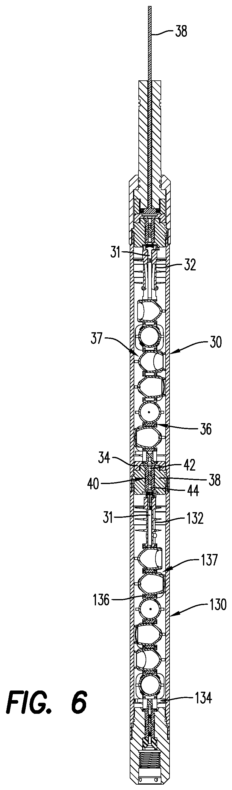
FIG. 6 is a side, cross-sectional view of a perforating gun including a detonating cord/electrically conductive detonating cord, according to an embodiment;
FIG. 6A is a side, perspective view of the perforating gun of FIG. 6, illustrating the arrangement of the electrically conductive detonating cord;
FIG. 6B is a side, perspective view of the perforating gun of FIG. 6, illustrating the arrangement of the components of the perforating gun;
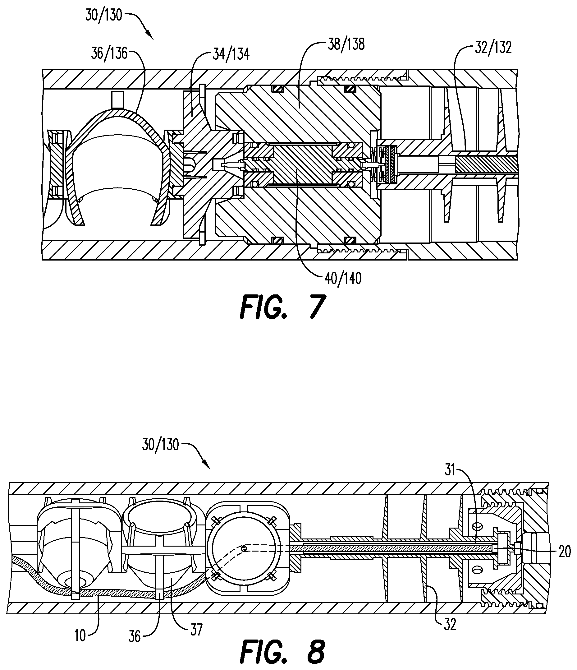
FIG. 7 is a side, cross-sectional view of a portion of the perforating gun of FIG. 6; and
FIG. 8 is a side, partial cross-sectional view of the perforating gun of FIG. 6, illustrating a detonator housed in a top connector, and a detonating cord extending from the top connector to a charge holder.
Various features, aspects, and advantages of the embodiments will become more apparent from the following detailed description, along with the accompanying figures in which like numerals represent like components throughout the figures and text. The various described features are not necessarily drawn to scale, but are drawn to emphasize specific features relevant to some embodiments.
The headings used herein are for organizational purposes only and are not meant to limit the scope of the description or the claims. To facilitate understanding, reference numerals have been used, where possible, to designate like elements common to the figures.
DETAILED DESCRIPTION
Reference will now be made in detail to various embodiments. Each example is provided by way of explanation and is not meant as a limitation and does not constitute a definition of all possible embodiments.
For purposes of illustrating features of the embodiments, reference be made to various figures. FIGS. 1A-1B illustrate various features of a detonating cord for use in a perforating gun/perforating gun assemblies. As will be discussed in connection with the individual illustrated embodiments, the detonator generally is connected electrically, which requires the transmission of a communication signal (i.e., electric current) through a lead wire or along the length of the conductive detonating cord. The electric current may be used to transmit telemetry signals, charge down-hole capacitors, initiate detonators in perforating gun assemblies, and communicate to other devices such as an igniter for bridge plug setting tool which are positioned below the perforating gun assembly. The electrically conductive materials of the detonating cord helps to reduce the number of required wires in perforating gun assemblies, and helps to facilitate the electrical connection between a plurality of perforating guns.
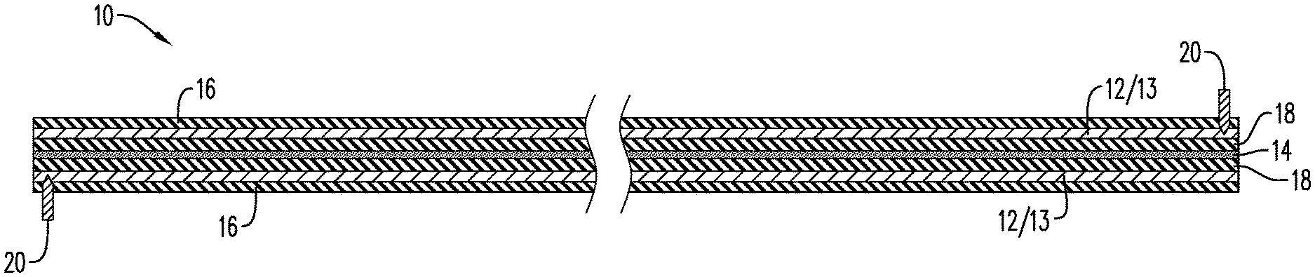
Embodiments of the disclosure may be associated with a detonating cord/electrically conductive detonating cord 10. The detonating cord 10 may be a flexible structure that allows the detonating cord 10 to be bent or wrapped around structures. According to an aspect, the detonating cord 10 may include a protective structure or sheath 16 that prevents the flow of an extraneous or stray electric current through the explosive layer 14 within the detonating cord 10.
According to an aspect, and as illustrated in FIGS. 1A-2B, the detonating cord 10 includes an explosive layer/linear explosive layer 14. The explosive layer 14 may include an insensitive secondary explosive (i.e., an explosive that is less sensitive to electrostatic discharge (ESD), friction and impact energy within the detonating cord, as compared to a primary explosive). According to an aspect, the explosive layer 14 includes at least one of pentaerythritol tetranitrate (PETN), cyclotrimethylenetrinitramine (RDX), octahydro-1,3,5,7-tetranitro-1,3,5,7-tetrazocine/cyclotetramethylene-tetr- anitramine (HMX), Hexanitrostilbene (HNS), 2,6-Bis(picrylamino)-3,5-dinitropyridine (PYX), and nonanitroterphenyl (NONA). The type of material selected to form the explosive layer 14 may be based at least in part on the temperature exposure, radial output and detonation velocity of the material/explosive. In an embodiment, the explosive layer includes a mixture of explosive materials, such as, HNS and NONA. As would be understood by one of ordinary skill in the art, the explosive layer 14 may include compressed explosive materials or compressed explosive powder. The explosive layer 14 may include constituents to improve the flowability of the explosive powder during the manufacturing process. Such constituents may include various dry lubricants, such as, plasticizers, graphite, and wax.
The detonating cord 10 further includes an electrically conductive layer 12. The electrically conductive layer 12 is configured to relay/transfer a communication signal along the length L of the detonating cord 10. The communication signal may be a telemetry signal. According to an aspect, the communication signal includes at least one of a signal to, check and count for detonators in a perforating gun string assembly, address and switch to certain detonators, charge capacitors and to send a signal to initiate a detonator communicably connected to the detonating cord 10. The integration of the electrically conductive layer 12 in the detonating cord 10 helps to omit the electric feed-through wires presently being used.
According to an aspect, the electrically conductive layer 12 extends around the explosive layer 14 in a spaced apart configuration. As will be described in further detail hereinbelow, an insulating layer 18 may be sandwiched between the explosive layer 12 and the electrically conductive layer 12. The electrically conductive layer 14 of the detonating cord 10 may include a plurality of electrically conductive threads/fibers spun or wrapped around the insulating layer 18, or an electrically conductive sheath/pre-formed electrically conductive sheath 13 in a covering relationship with the insulating layer 18. According to an aspect, the electrically conductive sheath 13 comprises layers of electrically conductive woven threads/fibers that are pre-formed into a desired shape that allows the electrically conductive sheath to be easily and efficiently placed or arranged over the insulating layer 18. The layers of electrically conductive woven threads may be configured in a type of crisscross or overlapping pattern in order to minimize the effective distance the electrical signal must travel when it traverses through the detonating cord 10. This arrangement of the threads helps to reduce the electrical resistance (Ohm/ft or Ohm/m) of the detonating cord 10. The electrically conductive threads and the electrically conductive woven threads may include metal fibers or may be coated with a metal, each metal fiber or metal coating having a defined resistance value (Ohm/ft or Ohm/m). It is contemplated that longer gun strings (i.e., more perforating guns in a single string) may be formed using perforating guns that including the electrically conductive detonating cord 10.
FIG. 1B and FIG. 2B illustrate the detonating cord 10 including an insulating layer 18. The insulating layer 18 is disposed/positioned between the explosive layer 14 and the electrically conductive layer 12. As illustrated in FIG. 2B, for example, the insulating layer 18 may extend along the length L of the detonating cord 10. According to an embodiment (not shown), the insulating layer 18 may only extend along a portion of the length L of the detonating cord, where the explosive layer 14 would potentially be adjacent the electrically conductive layer 12. The insulating layer may be formed of any nonconductive material. According to an aspect, the insulating layer 18 may include at least one of a plurality of non-conductive aramid threads, a polymer, such as fluorethylenpropylene (FEP), polyamide (PA), polyethylenterephthalate (PET), or polyvinylidenfluoride (PVDF), and a coloring additive.
The detonating cord 10 may include a layer of material along its external surface to impart additional strength and protection to the structure of the detonating cord 10. FIGS. 1A-2B each illustrate a jacket/outer protective jacket 16 externally positioned on the detonating cord 10. According to an aspect, the jacket 16 is formed of at least one layer of woven threads. The jacket 16 may be formed from a nonconductive polymer material, such as FEP, PA, PET, and PVDF. According to an aspect, the jacket 16 is formed of at least one layer of non-conductive woven threads and covered by a sheath formed from a plastic, composite or lead.
As illustrated in FIGS. 1A and 1B, the jacket 16 extends around/surrounds/encases the electrically conductive layer 12 or the electrically conductive sheath 13, the insulating layer 18, and the explosive layer 14. The jacket 16 extends along the length L of the detonating cord 10, and may be impervious to at least one of sour gas (H.sub.2S), water, drilling fluid, and electrical current.
According to an aspect, electric pulses, varying or alternating current or constant/direct current may be induced into or retrieved from the electrically conductive layer 12/electrically conductive sheath 13 of the detonating cord 10. FIG. 3A and FIG. 3B illustrate the detonating cord 10 including contacts 20. According to an aspect, the contacts 20 may include a metal, such as aluminum, brass, copper, stainless steel or galvanized steel (including zinc).
The contacts 20 are configured to input a communication signal at a first end/contact portion of the detonating cord 10 and output the communication signal at a second end/contact portion of the detonating cord 10. In order to facilitate the communication of the communication signal, the contacts 20 may at least partially be embedded into the detonating cord 10. The contacts 20 may be coupled to or otherwise secured to the detonating cord 10. According to an aspect, the contacts 20 are crimped onto the detonating cord 10, in such a way that the contacts 20 pierce through the protective outer jacket 16 of the detonating cord 10 to engage the electrically conductive layer 12 or the conductive sheath 13.
FIG. 4A illustrates the contacts 20 extending around and cutting into a portion of the jacket 16. The contact may include a split sleeve 21, that engages and contacts with at least a portion of the electrically conductive layer 12. The split sleeve 21 includes a longitudinal split, which allows the split sleeve 21 to be temporarily bent or deformed to be placed on or be positioned over the detonating cord 10. The split sleeve 21 may include a plurality of retention features (not shown) that pierce through the jacket 16 and engages with the electrically conductive threads 12.
FIGS. 4B and 4C illustrate the contacts 20 including a conductive pin 22. The conductive pin 22 includes an upper portion 23, and at least one lower portion 24 extending from the upper portion 23. The lower portion 24 is configured for engaging the electrically conductive layer 12 of the detonating cord, while the upper portion 23 facilitates the proper placement/arrangement of the conductive pin 22 and, if necessary, facilitates the removal of the conductive pin 22 from the detonating cord 10. As illustrated, for instance, in FIG. 5, the lower portion 24 may be sized to extend across (partially or fully) a width W of the detonating cord 10. According to an aspect and as illustrated in FIG. 4C and FIG. 5, the lower portion 24 may include a plurality of retention mechanisms 25. The retention mechanisms 25 may be shaped as spikes or as barbs that engage with at least one of the layers of the detonating cord 10. FIG. 5 illustrates the retention mechanisms 25 pierced through the entire width W of the detonating cord 10.
While the arrangements of the layers of the detonating cord 10 have been illustrated in FIGS. 1A-5 and described in detail hereinabove, it is to be understood that the layers may be arranged in different orders based on the application in which the detonating cord 10 will be used. For example, the electrically conductive layer 12 may be the innermost layer, with the insulating layer 18 adjacent the conductive layer, and the explosive layer 14 extending around the insulating layer 18 (not shown). The jacket 16 extends around the layers and helps protect the detonating cord 10 from damage and exposure to undesired friction and liquids.
Further embodiments of the disclosure are associated with a perforating gun 30/adjacent perforating guns 130, as illustrated in FIGS. 6A-8. FIGS. 6, 6A and 6B and FIG. 7 illustrate the perforating gun 30/130 including a top connector 32, a bottom connector 34, and a charge holder 36. As illustrated in FIG. 6, multiple charge holders 36 may extend between the top and bottom connectors 32, 34. Each charge holder 36 is configured for holding a shaped charge 37. The shaped charges 37 may be of any size or of any general shape, such as conical or rectangular. While the shaped charges 37 illustrated are open/un-encapsulated shaped charges, it is contemplated that the charge holders 36 may include encapsulated shaped charges.
As illustrated in FIGS. 6A and 8, the perforating gun 30/130 includes a detonating cord 10. The detonating cord 10 may extend from the top connector 32 to the bottom connector 34, and may be connected to each of the shaped charges 37 positioned in the perforating gun 30. The detonating cord 10 is configured to initiate the shaped charge 37 disposed in each charge holder 36. For purposes of convenience, and not limitation, the general characteristics of the detonating cord 10 described hereinabove with respect to FIGS. 1A-5, are not repeated here.
The detonating cord 10 electrically connects the top connector 32 to the bottom connector 34, which in return connects to an adjacent perforating gun 130 (FIGS. 6, 6A-6B and FIG. 7). In this configuration, the detonating cord 10 electrically connects contact points/areas in the top connector 32 of the perforating gun 30 to a corresponding contact point/area in the bottom connector 134 of an adjacent perforating gun 130. According to an aspect, the top connector 132 of the adjacent perforating gun 130 may be electrically connected to a corresponding bottom connector of another adjacent perforating gun.
The perforating gun 30/adjacent perforating gun 130 may include one or more contacts 20, configured substantially as described hereinabove and illustrated in FIGS. 3A-5. Thus, for purposes of convenience and not limitation, the features and structure of the contacts 20 described above and illustrated in FIGS. 3A-5 are not repeated here. According to an aspect, the contacts may include a first contact and a second contact. The first contact may be positioned or otherwise disposed in the top connector 32, while the second contact may be positioned or otherwise disposed in the bottom connector 34 (FIGS. 6A-6B and 8).
The perforating gun 30 may further include a tandem seal adapter 38 configured for housing a bulkhead assembly 40. The bulkhead assembly 40 may include a first end/first electrical contact end 42 and a second end/second electrical contact end 44. According to an aspect, the first end 42 is electrically connected to the bottom connector 34 of the perforating gun 30, and the second end 44 is electrically connected to a top connector 132 of an adjacent (or downstream) perforating gun 130. According to an aspect, a communication signal is communicated through the bulkhead assembly of the tandem seal adapter 38 to the adjacent perforating gun 130, via at least the detonating cord 10 including the electrically conductive layer 12.
FIG. 8 illustrates a detonator 31 arranged in the top connector 32. The detonator 31 is energetically and electrically coupled to the detonating cord 10 through the contacts 20. As described in detail hereinabove, the contacts 20 input the communication signal at a first end/contact portion 11a of the detonating cord 10 and output the communication signal at a second end/contact portion 11b of the detonating cord 10. The communication signal is at least one of a telemetry signal, a signal to check and count for detonators in the gun string assembly, address and switch to certain detonators, to charge capacitors, and a signal to initiate the detonator 31.
According to an aspect, the detonator 31 is one of an RF-safe electronic detonator, a resistorized/electric detonator, or a detonator using a fire set, an EFI, an EBW, a semiconductor bridge and/or an igniter. The detonator 31 may include a line-in portion, and a line-out portion and a grounding contact. The line-in portion of the detonator 31 may be connected to the second end 44 of the bulkhead assembly 40, which may be electrically connected to the top connector 132 of the adjacent perforating gun 130. The line-out portion of the detonator 31 may connect to the first end 42 of an adjacent bulkhead assembly 140 that is electrically connected to a bottom connector 134 of the adjacent perforating gun 130. According to an aspect, the adjacent perforating gun 130 may be a bottommost perforating gun, and the communication signal may be an electric signal that is relayed/transferred to the bottommost perforating gun from the top perforating gun 30.
The present disclosure, in various embodiments, configurations and aspects, includes components, methods, processes, systems and/or apparatus substantially developed as depicted and described herein, including various embodiments, sub-combinations, and subsets thereof. Those of skill in the art will understand how to make and use the present disclosure after understanding the present disclosure. The present disclosure, in various embodiments, configurations and aspects, includes providing devices and processes in the absence of items not depicted and/or described herein or in various embodiments, configurations, or aspects hereof, including in the absence of such items as may have been used in previous devices or processes, e.g., for improving performance, achieving ease and/or reducing cost of implementation.
The phrases "at least one", "one or more", and "and/or" are open-ended expressions that are both conjunctive and disjunctive in operation. For example, each of the expressions "at least one of A, B and C", "at least one of A, B, or C", "one or more of A, B, and C", "one or more of A, B, or C" and "A, B, and/or C" means A alone, B alone, C alone, A and B together, A and C together, B and C together, or A, B and C together.
In this specification and the claims that follow, reference will be made to a number of terms that have the following meanings. The terms "a" (or "an") and "the" refer to one or more of that entity, thereby including plural referents unless the context clearly dictates otherwise. As such, the terms "a" (or "an"), "one or more" and "at least one" can be used interchangeably herein. Furthermore, references to "one embodiment", "some embodiments", "an embodiment" and the like are not intended to be interpreted as excluding the existence of additional embodiments that also incorporate the recited features. Approximating language, as used herein throughout the specification and claims, may be applied to modify any quantitative representation that could permissibly vary without resulting in a change in the basic function to which it is related. Accordingly, a value modified by a term such as "about" is not to be limited to the precise value specified. In some instances, the approximating language may correspond to the precision of an instrument for measuring the value. Terms such as "first," "second," "upper," "lower" etc. are used to identify one element from another, and unless otherwise specified are not meant to refer to a particular order or number of elements.
As used herein, the terms "may" and "may be" indicate a possibility of an occurrence within a set of circumstances; a possession of a specified property, characteristic or function; and/or qualify another verb by expressing one or more of an ability, capability, or possibility associated with the qualified verb. Accordingly, usage of "may" and "may be" indicates that a modified term is apparently appropriate, capable, or suitable for an indicated capacity, function, or usage, while taking into account that in some circumstances the modified term may sometimes not be appropriate, capable, or suitable. For example, in some circumstances an event or capacity can be expected, while in other circumstances the event or capacity cannot occur--this distinction is captured by the terms "may" and "may be."
As used in the claims, the word "comprises" and its grammatical variants logically also subtend and include phrases of varying and differing extent such as for example, but not limited thereto, "consisting essentially of" and "consisting of." Where necessary, ranges have been supplied, and those ranges are inclusive of all sub-ranges therebetween. It is to be expected that variations in these ranges will suggest themselves to a practitioner having ordinary skill in the art and, where not already dedicated to the public, the appended claims should cover those variations.
The foregoing discussion of the present disclosure has been presented for purposes of illustration and description. The foregoing is not intended to limit the present disclosure to the form or forms disclosed herein. In the foregoing Detailed Description for example, various features of the present disclosure are grouped together in one or more embodiments, configurations, or aspects for the purpose of streamlining the disclosure. The features of the embodiments, configurations, or aspects of the present disclosure may be combined in alternate embodiments, configurations, or aspects other than those discussed above. This method of disclosure is not to be interpreted as reflecting an intention that the present disclosure requires more features than are expressly recited in each claim. Rather, as the following claims reflect, the claimed features lie in less than all features of a single foregoing disclosed embodiment, configuration, or aspect. Thus, the following claims are hereby incorporated into this Detailed Description, with each claim standing on its own as a separate embodiment of the present disclosure.
Advances in science and technology may make equivalents and substitutions possible that are not now contemplated by reason of the imprecision of language; these variations should be covered by the appended claims. This written description uses examples to disclose the method, machine and computer-readable medium, including the best mode, and also to enable any person of ordinary skill in the art to practice these, including making and using any devices or systems and performing any incorporated methods. The patentable scope thereof is defined by the claims, and may include other examples that occur to those of ordinary skill in the art. Such other examples are intended to be within the scope of the claims if they have structural elements that do not differ from the literal language of the claims, or if they include equivalent structural elements with insubstantial differences from the literal language of the claims.
* * * * *
References
-
sciencedirect.com/science/article/pii/S0264127515309345
-
hunting-intl.com/media/2674690/White%20Paper%20-%20H-1%20Perforating%20Gun%20Systems_January%202017.pdf
-
jetresearch.com/content/dam/jrc/Documents/Books_Catalogs/06_Dets.pdf
-
-
-
corelab.com/owen/cms/docs/Canada/10A_erhsc-01.0-c.pdf
-
-
austinpowder.com/wp-content/uploads/2019/01/OilStar_A140Fbk-2.pdf
-
burndy.com/docs/default-source/cutsheets/bulkhead-connect
-
-
djresource.eu/Topics/story/110/Technics-SL-Replacing-Signal-and-Ground-Wire
-
dynaenergetics.com
-
-
-
-
-
merriam-webster.com/dictionary/insulator
-
vigordrilling.com/completion-tools/perforating-gun-accessories.html
D00000
D00001
D00002
D00003
D00004
D00005
D00006
D00007
D00008
XML
uspto.report is an independent third-party trademark research tool that is not affiliated, endorsed, or sponsored by the United States Patent and Trademark Office (USPTO) or any other governmental organization. The information provided by uspto.report is based on publicly available data at the time of writing and is intended for informational purposes only.
While we strive to provide accurate and up-to-date information, we do not guarantee the accuracy, completeness, reliability, or suitability of the information displayed on this site. The use of this site is at your own risk. Any reliance you place on such information is therefore strictly at your own risk.
All official trademark data, including owner information, should be verified by visiting the official USPTO website at www.uspto.gov. This site is not intended to replace professional legal advice and should not be used as a substitute for consulting with a legal professional who is knowledgeable about trademark law.