Insulated box assembly with overlapping panels
Sollie , et al. November 24, 2
U.S. patent number 10,843,840 [Application Number 16/567,192] was granted by the patent office on 2020-11-24 for insulated box assembly with overlapping panels. This patent grant is currently assigned to Pratt Retail Specialties, LLC. The grantee listed for this patent is Pratt Retail Specialties, LLC. Invention is credited to Shifeng Chen, Greg Sollie, Jamie Waltermire.


View All Diagrams
| United States Patent | 10,843,840 |
| Sollie , et al. | November 24, 2020 |
Insulated box assembly with overlapping panels
Abstract
A method of assembling a box assembly, comprising: folding an exterior piece from a flat configuration to a three-dimensional configuration defining a cavity, the exterior piece comprising a plurality of middle portions and a plurality of upper portions joined to the middle portions by fold lines; folding an interior piece from a flat configuration to a three-dimensional configuration defining a cavity, the interior piece comprising a bottom panel and a plurality of side panels; inserting the interior piece into the exterior piece to define a space between the middle portions of the exterior piece and the side panels of the interior piece; and folding the upper portions of the exterior piece to cover the space.
| Inventors: | Sollie; Greg (Sharpsburg, GA), Waltermire; Jamie (Peachtree City, GA), Chen; Shifeng (Newport News, VA) | ||||||||||
|---|---|---|---|---|---|---|---|---|---|---|---|
| Applicant: |
|
||||||||||
| Assignee: | Pratt Retail Specialties, LLC
(Conyers, GA) |
||||||||||
| Family ID: | 1000005200840 | ||||||||||
| Appl. No.: | 16/567,192 | ||||||||||
| Filed: | September 11, 2019 |
Prior Publication Data
| Document Identifier | Publication Date | |
|---|---|---|
| US 20200148410 A1 | May 14, 2020 | |
Related U.S. Patent Documents
| Application Number | Filing Date | Patent Number | Issue Date | ||
|---|---|---|---|---|---|
| 16382710 | Apr 12, 2019 | ||||
| 62760672 | Nov 13, 2018 | ||||
| Current U.S. Class: | 1/1 |
| Current CPC Class: | B65D 5/64 (20130101); B65D 81/3858 (20130101); B65D 5/22 (20130101); B65D 5/2057 (20130101); B31B 50/262 (20170801); B65D 81/386 (20130101); B65D 25/02 (20130101); B31B 2110/35 (20170801) |
| Current International Class: | B31B 50/26 (20170101); B65D 5/22 (20060101); B65D 5/64 (20060101); B65D 25/02 (20060101); B65D 5/20 (20060101); B65D 81/38 (20060101) |
| Field of Search: | ;229/103.11,122.32,122.34 ;220/592.25,592.2,592.26,4.29,592.23 ;206/594,545 ;312/259 ;62/60 |
References Cited [Referenced By]
U.S. Patent Documents
| 265985 | October 1882 | Seabury |
| 1527167 | February 1925 | Birdseye |
| 1677565 | July 1928 | Oppenheim |
| 1682410 | August 1928 | Oppenheim |
| 1747980 | February 1930 | Kondolf |
| 1753813 | April 1930 | Washburn |
| 1868996 | July 1932 | Sharp |
| 1896393 | February 1933 | Devine |
| 1899892 | February 1933 | D'Este et al. |
| 1930680 | October 1933 | Hinton |
| 1935923 | November 1933 | Thoke |
| 1937263 | November 1933 | Bubb |
| 1942917 | January 1934 | D'Este et al. |
| 1954013 | April 1934 | Lilienfield |
| 2018519 | October 1935 | Hall |
| 2070747 | February 1937 | Ostrom |
| 2116513 | May 1938 | Frankenstein |
| 2148454 | February 1939 | Gerard |
| 2165327 | July 1939 | Zalkind |
| 2289060 | July 1942 | Merkle |
| 2293361 | August 1942 | Roberts |
| 2360806 | October 1944 | Van Rosen |
| 2386905 | October 1945 | Meitzen |
| 2389601 | November 1945 | De Witt |
| 2554004 | May 1951 | Bergstein |
| 2632311 | March 1953 | Sullivan |
| 2650016 | August 1953 | McMillan |
| 2753102 | July 1956 | Paige |
| 2899103 | August 1959 | Ebert |
| 2927720 | March 1960 | Adams |
| 2987239 | June 1961 | Atwood |
| 3029008 | April 1962 | Membrino |
| 3031121 | April 1962 | Chase |
| 3065895 | November 1962 | Lipschutz |
| 3096879 | July 1963 | Schumacher |
| 3097782 | July 1963 | Koropatkin et al. |
| 3182913 | May 1965 | Brian |
| 3193176 | July 1965 | Gullickson et al. |
| 3222843 | December 1965 | Schneider |
| 3236206 | February 1966 | Willinger |
| 3282411 | November 1966 | Jardine |
| 3286825 | November 1966 | Laas |
| 3335941 | August 1967 | Gatward |
| 3371462 | March 1968 | Nordkvist et al. |
| 3375934 | April 1968 | Bates |
| 3420363 | January 1969 | Blickensderfer |
| 3435736 | April 1969 | Reiche |
| 3503550 | March 1970 | Main et al. |
| 3551945 | January 1971 | Eyberg et al. |
| 3670948 | June 1972 | Berg |
| 3703383 | November 1972 | Kuchenbecker |
| 3734336 | May 1973 | Rankow et al. |
| 3747743 | July 1973 | Hoffman, Jr. |
| 3749299 | July 1973 | Ingle |
| 3836044 | September 1974 | Tilp et al. |
| 3843038 | October 1974 | Sax |
| 3880341 | April 1975 | Bamburg et al. |
| 3887743 | June 1975 | Lane |
| 3890762 | June 1975 | Ernst et al. |
| 3980005 | September 1976 | Buonaiuto |
| 4030227 | June 1977 | Oftedahl |
| 4050264 | September 1977 | Tanaka |
| 4068779 | January 1978 | Canfield |
| 4091852 | May 1978 | Jordan et al. |
| 4169540 | October 1979 | Larsson et al. |
| 4211267 | July 1980 | Skovgaard |
| 4213310 | July 1980 | Buss |
| 4335844 | June 1982 | Egli |
| 4342416 | August 1982 | Philips |
| 4380314 | April 1983 | Langston, Jr. et al. |
| 4396144 | August 1983 | Gutierrez et al. |
| 4418864 | December 1983 | Neilsen |
| 4488623 | December 1984 | Linnell, II et al. |
| 4509645 | April 1985 | Hotta |
| 4679242 | July 1987 | Brockhaus |
| 4682708 | July 1987 | Pool |
| 4819793 | April 1989 | Willard et al. |
| 4828133 | May 1989 | Hougendobler |
| 4830282 | May 1989 | Knight, Jr. |
| 4889252 | December 1989 | Rockom et al. |
| 4930903 | June 1990 | Mahoney |
| 4989780 | February 1991 | Foote et al. |
| 5016813 | May 1991 | Simons |
| 5020481 | June 1991 | Nelson |
| 5062527 | November 1991 | Westerman |
| 5094547 | March 1992 | Graham |
| 5102004 | April 1992 | Hollander et al. |
| 5154309 | October 1992 | Wischusen, III et al. |
| 5158371 | October 1992 | Moravek |
| 5165583 | November 1992 | Kouwenberg |
| 5185904 | February 1993 | Rogers et al. |
| 5263339 | November 1993 | Evans |
| 5358757 | October 1994 | Robinette et al. |
| 5372429 | December 1994 | Beaver, Jr. et al. |
| 5417342 | May 1995 | Hutchison |
| 5418031 | May 1995 | English |
| 5441170 | August 1995 | Bane, III |
| 5454471 | October 1995 | Norvell |
| 5491186 | February 1996 | Kean et al. |
| 5493874 | February 1996 | Landgrebe |
| 5499473 | March 1996 | Ramberg |
| 5505810 | April 1996 | Kirby et al. |
| 5511667 | April 1996 | Carder |
| 5512345 | April 1996 | Tsutsumi et al. |
| 5516580 | May 1996 | Frenette et al. |
| 5562228 | October 1996 | Ericson |
| 5573119 | November 1996 | Luray |
| 5596880 | January 1997 | Welker et al. |
| 5613610 | March 1997 | Bradford |
| 5615795 | April 1997 | Tipps |
| 5638978 | June 1997 | Cadiente |
| 5775576 | July 1998 | Stone |
| 5842571 | December 1998 | Rausch |
| 5906290 | May 1999 | Haberkorn |
| 5996366 | December 1999 | Renard |
| 6003719 | December 1999 | Steward, III |
| 6041958 | March 2000 | Tremelo |
| 6050412 | April 2000 | Clough et al. |
| 6138902 | October 2000 | Welch |
| 6164526 | December 2000 | Dalvey |
| 6168040 | January 2001 | Sautner et al. |
| 6220473 | April 2001 | Lehman et al. |
| 6223551 | May 2001 | Mitchell |
| 6238091 | May 2001 | Mogil |
| 6244458 | June 2001 | Frysinger et al. |
| 6247328 | June 2001 | Mogil |
| 6295830 | October 2001 | Newman |
| 6295860 | October 2001 | Sakairi et al. |
| 6308850 | October 2001 | Coom et al. |
| 6325281 | December 2001 | Grogan |
| 6443309 | September 2002 | Becker |
| 6453682 | September 2002 | Jennings et al. |
| 6478268 | November 2002 | Bidwell et al. |
| 6510705 | January 2003 | Jackson |
| 6582124 | June 2003 | Mogil |
| 6618868 | September 2003 | Minnick |
| 6688133 | February 2004 | Donefrio |
| 6725783 | April 2004 | Sekino |
| 6726017 | April 2004 | Maresh et al. |
| 6736309 | May 2004 | Westerman et al. |
| 6771183 | August 2004 | Hunter |
| 6821019 | November 2004 | Mogil |
| 6837420 | January 2005 | Westerman et al. |
| 6868982 | March 2005 | Gordon |
| 6875486 | April 2005 | Miller |
| 6899229 | May 2005 | Dennison et al. |
| 6910582 | June 2005 | Lantz |
| 6971539 | December 2005 | Abbe |
| 7000962 | February 2006 | Le |
| 7019271 | March 2006 | Wnek et al. |
| 7094192 | August 2006 | Schoenberger et al. |
| 7140773 | November 2006 | Becker et al. |
| 7225632 | June 2007 | Derifield |
| 7225970 | June 2007 | Philips |
| 7229677 | June 2007 | Miller |
| 7264147 | September 2007 | Benson et al. |
| 7392931 | July 2008 | Issler |
| 7452316 | November 2008 | Cals et al. |
| D582676 | December 2008 | Rothschild |
| 7597209 | October 2009 | Rothschild et al. |
| 7607563 | October 2009 | Hanna et al. |
| 7677406 | March 2010 | Maxson |
| 7681405 | March 2010 | Williams |
| 7784301 | August 2010 | Sasaki et al. |
| 7807773 | October 2010 | Matsuoka et al. |
| 7841512 | November 2010 | Westerman et al. |
| 7845508 | December 2010 | Rothschild et al. |
| 7870992 | January 2011 | Schille et al. |
| 7909806 | March 2011 | Goodman et al. |
| 7971720 | July 2011 | Minkler |
| 8118177 | February 2012 | Drapela et al. |
| 8343024 | January 2013 | Contanzo, Jr. et al. |
| 8365943 | February 2013 | Bentley |
| 8465404 | June 2013 | Hadley |
| 8579183 | November 2013 | Belfort et al. |
| 8596520 | December 2013 | Scott |
| 8613202 | December 2013 | Williams |
| 8651593 | February 2014 | Bezich et al. |
| 8763811 | July 2014 | Lantz |
| 8763886 | July 2014 | Hall |
| 8795470 | August 2014 | Henderson et al. |
| 8919082 | December 2014 | Cataldo |
| 8960528 | February 2015 | Sadlier |
| 9272475 | March 2016 | Ranade et al. |
| 9290313 | March 2016 | De Lesseux et al. |
| 9322136 | April 2016 | Ostendorf et al. |
| D758182 | June 2016 | Sponselee |
| 9408445 | August 2016 | Mogil et al. |
| 9429350 | August 2016 | Chapman, Jr. |
| 9499294 | November 2016 | Contanzo, Jr. |
| 9550618 | January 2017 | Jobe |
| 9605382 | March 2017 | Virtanen |
| 9611067 | April 2017 | Collison |
| 9635916 | May 2017 | Bezich et al. |
| 9701437 | July 2017 | Bugas et al. |
| 9738420 | August 2017 | Miller |
| 9738432 | August 2017 | Petrucci et al. |
| 9834366 | December 2017 | Giuliani |
| 9908680 | March 2018 | Shi et al. |
| 9908684 | March 2018 | Collison |
| 9920517 | March 2018 | Sollie et al. |
| 9950830 | April 2018 | De Lesseux et al. |
| 9981797 | May 2018 | Aksan et al. |
| 10046901 | August 2018 | Jobe |
| 10094126 | October 2018 | Collison et al. |
| 10112756 | October 2018 | Menzel, Jr. |
| 10226909 | March 2019 | Frem et al. |
| 10266332 | April 2019 | Aksan et al. |
| 10442600 | October 2019 | Waltermire et al. |
| 10507968 | December 2019 | Sollie et al. |
| 10551110 | February 2020 | Waltermire et al. |
| 10583977 | March 2020 | Collison et al. |
| 2001/0010312 | August 2001 | Mogil |
| 2002/0020188 | February 2002 | Sharon et al. |
| 2002/0162767 | November 2002 | Ohtsubo |
| 2003/0145561 | August 2003 | Cals et al. |
| 2004/0004111 | January 2004 | Cardinale |
| 2004/0031842 | February 2004 | Westerman et al. |
| 2004/0079794 | April 2004 | Mayer |
| 2005/0109655 | May 2005 | Vershum et al. |
| 2005/0189404 | September 2005 | Xiaohai et al. |
| 2005/0214512 | September 2005 | Fascio |
| 2005/0224501 | October 2005 | Folkert et al. |
| 2005/0279963 | December 2005 | Church et al. |
| 2006/0053828 | March 2006 | Shallman et al. |
| 2006/0078720 | April 2006 | Toas et al. |
| 2006/0096978 | May 2006 | Lafferty et al. |
| 2006/0193541 | August 2006 | Norcom |
| 2007/0000932 | January 2007 | Cron et al. |
| 2007/0000983 | January 2007 | Spurrell et al. |
| 2007/0051782 | March 2007 | Lantz |
| 2007/0193298 | August 2007 | Derifield |
| 2007/0209307 | September 2007 | Andersen |
| 2007/0257040 | November 2007 | Price, Jr. et al. |
| 2008/0095959 | April 2008 | Warner et al. |
| 2008/0135564 | June 2008 | Romero |
| 2008/0173703 | July 2008 | Westerman et al. |
| 2008/0190940 | August 2008 | Scott |
| 2008/0203090 | August 2008 | Dickinson |
| 2008/0289302 | November 2008 | Vulpitta |
| 2008/0296356 | December 2008 | Hatcher et al. |
| 2008/0308616 | December 2008 | Phung |
| 2008/0314794 | December 2008 | Bowman |
| 2009/0034883 | February 2009 | Giuliani |
| 2009/0114311 | May 2009 | McDowell |
| 2009/0193765 | August 2009 | Lantz |
| 2009/0214142 | August 2009 | Bossel et al. |
| 2009/0283578 | November 2009 | Miller |
| 2010/0001056 | January 2010 | Chandaria |
| 2010/0006630 | January 2010 | Humphries et al. |
| 2010/0062921 | March 2010 | Veiseh |
| 2010/0072105 | March 2010 | Glaser et al. |
| 2010/0139878 | June 2010 | Clemente |
| 2010/0151164 | June 2010 | Grant et al. |
| 2010/0282827 | November 2010 | Padovani |
| 2010/0284634 | November 2010 | Hadley |
| 2010/0314397 | December 2010 | Williams et al. |
| 2010/0314437 | December 2010 | Dowd |
| 2011/0042449 | February 2011 | Copenhaver et al. |
| 2011/0100868 | May 2011 | Lantz |
| 2011/0114513 | May 2011 | Miller |
| 2011/0235950 | September 2011 | Lin |
| 2011/0284556 | November 2011 | Palmer et al. |
| 2011/0311758 | December 2011 | Burns et al. |
| 2011/0317944 | December 2011 | Liu |
| 2012/0031957 | February 2012 | Whitaker |
| 2012/0074823 | March 2012 | Bezich et al. |
| 2012/0145568 | June 2012 | Collison et al. |
| 2012/0243808 | September 2012 | De Lesseux et al. |
| 2012/0248101 | October 2012 | Tumber et al. |
| 2012/0251818 | October 2012 | Axrup et al. |
| 2012/0279896 | November 2012 | Lantz |
| 2013/0112694 | May 2013 | Bentley |
| 2013/0112695 | May 2013 | Hall |
| 2013/0140317 | June 2013 | Roskoss |
| 2014/0000306 | January 2014 | Chapman, Jr. |
| 2014/0021208 | January 2014 | Anti et al. |
| 2014/0093697 | April 2014 | Perry et al. |
| 2014/0248003 | September 2014 | Mogil et al. |
| 2014/0319018 | October 2014 | Collison |
| 2014/0367393 | December 2014 | Ranade |
| 2015/0110423 | April 2015 | Fox et al. |
| 2015/0166244 | June 2015 | Wood et al. |
| 2015/0175338 | June 2015 | Culp et al. |
| 2015/0238033 | August 2015 | Zavitsanos |
| 2015/0239639 | August 2015 | Wenner et al. |
| 2015/0259126 | September 2015 | McGoff et al. |
| 2015/0284131 | October 2015 | Genender et al. |
| 2015/0345853 | December 2015 | Oeyen |
| 2016/0015039 | January 2016 | Pierce |
| 2016/0052696 | February 2016 | Cook et al. |
| 2016/0060017 | March 2016 | De Lesseux et al. |
| 2016/0304267 | October 2016 | Aksan |
| 2016/0325915 | November 2016 | Aksan |
| 2017/0015080 | January 2017 | Collison et al. |
| 2017/0043937 | February 2017 | Lantz |
| 2017/0198959 | July 2017 | Morris |
| 2017/0225870 | August 2017 | Collison |
| 2017/0233134 | August 2017 | Grajales et al. |
| 2017/0283157 | October 2017 | Jobe |
| 2017/0305639 | October 2017 | Kuhn et al. |
| 2017/0320653 | November 2017 | Mogil et al. |
| 2017/0334622 | November 2017 | Menzel, Jr. |
| 2017/0341847 | November 2017 | Chase et al. |
| 2017/0369226 | December 2017 | Chase et al. |
| 2018/0050857 | February 2018 | Collison |
| 2018/0051460 | February 2018 | Sollie et al. |
| 2018/0148246 | May 2018 | Fu et al. |
| 2018/0194534 | July 2018 | Jobe |
| 2018/0215525 | August 2018 | Vogel et al. |
| 2018/0229917 | August 2018 | Jobe |
| 2018/0237207 | August 2018 | Aksan et al. |
| 2018/0274837 | September 2018 | Christensen |
| 2018/0290813 | October 2018 | Waltermire et al. |
| 2018/0290815 | October 2018 | Waltermire et al. |
| 2018/0299059 | October 2018 | McGoff et al. |
| 2018/0327171 | November 2018 | Waltermire et al. |
| 2018/0327172 | November 2018 | Waltermire et al. |
| 2018/0334308 | November 2018 | Moore et al. |
| 2018/0335241 | November 2018 | Li et al. |
| 2019/0032991 | January 2019 | Waltermire et al. |
| 2019/0047775 | February 2019 | Waltermire et al. |
| 2019/0185246 | June 2019 | Sollie et al. |
| 2019/0185247 | June 2019 | Sollie et al. |
| 2019/0193916 | June 2019 | Waltermire et al. |
| 2019/0210790 | July 2019 | Rizzo et al. |
| 2019/0234679 | August 2019 | Waltermire et al. |
| 2019/0248573 | August 2019 | Collison et al. |
| 2019/0270572 | September 2019 | Collison et al. |
| 2019/0270573 | September 2019 | Collison et al. |
| 2019/0352075 | November 2019 | Waltermire et al. |
| 2019/0352076 | November 2019 | Waltermire et al. |
| 2019/0352080 | November 2019 | Waltermire et al. |
| 2019/0359412 | November 2019 | Sollie et al. |
| 2019/0359413 | November 2019 | Sollie et al. |
| 2019/0359414 | November 2019 | Sollie et al. |
| 2019/0367209 | December 2019 | Jobe |
| 2019/0376636 | December 2019 | Fellinger et al. |
| 2019/0382186 | December 2019 | Sollie et al. |
| 2019/0390892 | December 2019 | Waltermire et al. |
| 2020/0088458 | March 2020 | Waltermire et al. |
| 2020/0103159 | April 2020 | Waltermire et al. |
| 2020/0122896 | April 2020 | Waltermire et al. |
| 2020/0148409 | May 2020 | Sollie et al. |
| 2020/0148453 | May 2020 | Sollie et al. |
| 2020/0283188 | September 2020 | Sollie et al. |
| 2019104 | Dec 1991 | CA | |||
| 206494316 | Sep 2017 | CN | |||
| 108001787 | May 2018 | CN | |||
| 1897846 | Jul 1964 | DE | |||
| 102011016500 | Oct 2012 | DE | |||
| 202017103230 | Jul 2017 | DE | |||
| 202017003908 | Oct 2017 | DE | |||
| 0133539 | Feb 1985 | EP | |||
| 0537058 | Apr 1993 | EP | |||
| 2990196 | Mar 2016 | EP | |||
| 1241878 | Sep 1960 | FR | |||
| 2705317 | Nov 1994 | FR | |||
| 2820718 | Aug 2002 | FR | |||
| 2821786 | Sep 2002 | FR | |||
| 3016352 | Jul 2015 | FR | |||
| 217683 | Jun 1924 | GB | |||
| 235673 | Jun 1925 | GB | |||
| 528289 | Jan 1940 | GB | |||
| 713640 | Aug 1954 | GB | |||
| 1204058 | Sep 1970 | GB | |||
| 1372054 | Oct 1974 | GB | |||
| 2400096 | May 2006 | GB | |||
| 2516490 | Jan 2015 | GB | |||
| 01254557 | Oct 1989 | JP | |||
| 2005139582 | Jun 2005 | JP | |||
| 2005247329 | Sep 2005 | JP | |||
| 2012126440 | Jul 2012 | JP | |||
| 8807476 | Oct 1988 | WO | |||
| 9726192 | Jul 1997 | WO | |||
| 9932374 | Jul 1999 | WO | |||
| 2001070592 | Sep 2001 | WO | |||
| 2014147425 | Sep 2014 | WO | |||
| 2016187435 | May 2016 | WO | |||
| 2016187435 | Nov 2016 | WO | |||
| 2018089365 | May 2018 | WO | |||
| 2018093586 | May 2018 | WO | |||
| 2018227047 | Dec 2018 | WO | |||
| 2019125904 | Jun 2019 | WO | |||
| 2019125906 | Jun 2019 | WO | |||
| 2019226199 | Nov 2019 | WO | |||
| 2020101939 | May 2020 | WO | |||
| 2020102023 | May 2020 | WO | |||
| 2020122921 | Jun 2020 | WO | |||
Other References
|
US 10,562,676 B2, 02/2020, Waltermire et al. (withdrawn) cited by applicant . Singh, et al; Article entitled: "Performance Comparison of Thermal Insulated Packaging Boxes, Bags and Refrigerants for Single-parcel Shipments", published Mar. 13, 2007, 19 pgs. cited by applicant . Periwrap; Article entitled: "Insulated Solutions", located at <https://www.peri-wrap.com/insulation/>, accessed on Dec. 3, 2018, 9 pgs. cited by applicant . UN Packaging; Article entitled: "CooLiner.RTM. Insulated Shipping Bags", available at <http://www.chem-tran.com/packaging/supplies/cooliner-insulated-shippi- ng-bags.php>, accessed on Aug. 30, 2017, 2 pgs. cited by applicant . Greenblue; "Environmental Technical Briefs of Common Packaging Materials--Fiber-Based Materials", Sustainable Packaging Solution, 2009. cited by applicant . MP Global Products; Article entitled: "Thermopod mailer envelopes and Thermokeeper insulated box liners", located at < http://www.mhpn.com/product/thermopod_mailer_envelopes_and_thermokeeper_i- nsulated_box_liners/packaging>, accessed on Aug. 30, 2017, 2 pgs. cited by applicant . Images of Novolex bag, including an outer paper bag, a corrugated cardboard insert, and an inner foil-covered bubble-wrap bag, publicly available prior to May 9, 2017, 7 pgs. cited by applicant . Duro Bag; Article entitled: "The Load and Fold Bag", accessed on May 24, 2017, copyrighted Apr. 2017, 3 pgs. cited by applicant . Tera-Pak; Article entitled: "Insulated Shipping Containers", located at <http://www.tera-pak.com/>, accessed on Mar. 20, 2017, 3 pgs. cited by applicant . American Bag Company; Article entitled: "Cool Green Bag, Small", located at <http://hotcoldbags.com/items/Cool%20Green%20Bag,%20Small>, accessed on Mar. 20, 2017, 2 pgs. cited by applicant . weiku.com; Article entitled: "100% Biodegradable Packing materials Green Cell Foam Stock Coolers", located at <http://www.weiku.com/products/18248504/100_Biodegradable_Packing_mate- rials_Green_Cell_Foam_Stock_Coolers.html>, accessed on Sep. 28, 2017, 7 pgs. cited by applicant . Salazar Packaging; Article entitle: "Custom Packaging and Design", located at <https://salazarpackaging.com/custom-packaging-and-design/>, accessed on Sep. 28, 2017, 2 pgs. cited by applicant . Voluntary Standard for Repulping and Recycling Corrugated Fiberboard Treated to Improve Its Performance in the Presence of Water and Water Vapor. (revises Aug. 16, 2013) Fibre Box Association (FBA), Elk Grove Village, IL, 1-23., Retrieved from http://www.corrugated.org/wp-content/uploads/PDFs/Recycling/Vol_Std_Proto- col_2013. pdf. cited by applicant . MP Global Products, LLC; International Search Report and Written Opinion of the International Searching Authority for PCT/US2017/060403, filed Nov. 7, 2017, dated Feb. 19, 2018, 15 pgs. cited by applicant . Cold Keepers; Article entitled: "Insulated Shipping Boxes--Coldkeepers, Thermal Shipping Solutions", located at <https://www.coldkeepers.com/product-category/shipping/>, (Accessed: Jan. 12, 2017), 3 pgs. cited by applicant . Needles `N` Knowledge; Article entitled: "Tall Box With Lid", located at <http://needlesnknowledge.blogspot.com/2017/10/tall-box-with-lid.html&- gt; (Accessed: Jan. 12, 2017), 10 pgs. cited by applicant . Sollie, Greg; Requirement for Restriction/Election for U.S. Appl. No. 16/382,710, filed Apr. 12, 2019, dated Jul. 15, 2019, 6 pgs. cited by applicant . Thomas Scientific; Article entitled: "Thermosafe: Test Tube Shipper/Rack", accessed on Oct. 26, 2018, 2 pgs. cited by applicant . Stinson, Elizabeth; Article entitled: "A Pizza Geek Discovers the World's Smartest Pizza Box", published Jan. 17, 2014, 8 pgs. cited by applicant . Sollie, Greg; Non-Final Office Action for U.S. Appl. No. 16/408,981, filed May 10, 2019, dated Aug. 20, 2019, 50 pgs. cited by applicant . Waltermire, Jamie; International Search Report and Written Opinion for PCT Application No. PCT/US18/65464, filed Dec. 13, 2018, dated Mar. 11, 2019, 9 pgs. cited by applicant . Sollie, Greg; International Search Report and Written Opinion for PCT Application No. PCT/US18/65459, filed Dec. 13, 2018, dated May 1, 2019, 15 pgs. cited by applicant . Sollie, Greg; International Search Report and Written Opinion for PCT Application No. PCT/US18/65461, filed Dec. 13, 2018, dated Mar. 21, 2019, 13 pgs. cited by applicant . Sollie, Greg; International Search Report and Written Opinion for PCT/US18/65463, filed Dec. 13, 2018, dated Mar. 25, 2019, 11 pgs. cited by applicant . Waltermire, Jamie; Non-Final Office Action for U.S. Appl. No. 15/482,186, filed Apr. 7, 2017, dated Aug. 20, 2019, 81 pgs. cited by applicant . Waltermire, Jamie; Requirement for Restriction/Election for U.S. Appl. No. 15/482,186, filed Apr. 7, 2017, dated Apr. 17, 2019, 7 pgs. cited by applicant . Waltermire, Jamie; Final Office Action for U.S. Appl. No. 15/482,200, filed Apr. 7, 2017, dated Jan. 2, 2019, 23 pgs. cited by applicant . Waltermire, Jamie; Non-Final Office Action for U.S. Appl. No. 15/482,200, filed Apr. 7, 2017, dated Jun. 11, 2018, 36 pgs. cited by applicant . Waltermire, Jamie; Notice of Allowance for U.S. Appl. No. 15/482,200, filed Apr. 7, 2017, dated May 14, 2019, 25 pgs. cited by applicant . Waltermire, Jamie; Supplemental Notice of Allowance for U.S. Appl. No. 15/482,200, filed Apr. 7, 2017, dated Jul. 26, 2019, 9 pgs. cited by applicant . Waltermire, Jamie; Supplemental Notice of Allowance for U.S. Appl. No. 15/482,200, filed Apr. 7, 2017, dated Aug. 12, 2019, 7 pgs. cited by applicant . Waltermire, Jamie; Supplemental Notice of Allowance for U.S. Appl. No. 15/482,200, filed Apr. 7, 2017, dated Sep. 10, 2019, 8 pgs. cited by applicant . Waltermire, Jamie; Final Office Action for U.S. Appl. No. 15/590,345, filed May 9, 2017, dated Mar. 19, 2019, 42 pgs. cited by applicant . Waltermire, Jamie; Non-Final Office Action for U.S. Appl. No. 15/590,345, filed May 9, 2017, dated Aug. 24, 2018, 41 pgs. cited by applicant . Waltermire, Jamie; Notice of Allowance for U.S. Appl. No. 15/590,345, filed May 9, 2017, dated Oct. 1, 2019, 28 pgs. cited by applicant . Waltermire, Jamie; Supplemental Notice of Allowance for U.S. Appl. No. 15/590,345, filed May 9, 2017, dated Dec. 3, 2019, 14 pgs. cited by applicant . Waltermire, Jamie; Applicant-Initiated Interview Summary for U.S. Appl. No. 15/590,349, filed May 9, 2017, dated Dec. 3, 2019, 3 pgs. cited by applicant . Waltermire, Jamie; Final Office Action for U.S. Appl. No. 15/590,349, filed May 9, 2017, dated May 9, 2019, 31 pgs. cited by applicant . Waltermire, Jamie; Non-Final Office Action for U.S. Appl. No. 15/590,349, filed May 9, 2017, dated Nov. 5, 2018, 41 pgs. cited by applicant . Waltermire, Jamie; Non-Final Office Action for U.S. Appl. No. 15/590,349, filed May 9, 2017, dated Sep. 5, 2019, 25 pgs. cited by applicant . Waltermire, Jamie; Requirement for Restriction/Election for U.S. Appl. No. 15/590,349, filed May 9, 2017, dated Aug. 30, 2018, 10 pgs. cited by applicant . Waltermire, Jamie; Corrected Notice of Allowance for U.S. Appl. No. 15/663,905, filed Jul. 31, 2017, dated Nov. 18, 2019, 6 pgs. cited by applicant . Waltermire, Jamie; Final Office Action for U.S. Appl. No. 15/663,905, filed Jul. 31, 2017, dated Aug. 22, 2019, 23 pgs. cited by applicant . Waltermire, Jamie; Non-Final Office Action for U.S. Appl. No. 15/663,905, filed Jul. 31, 2017, dated Jun. 25, 2019, 66 pgs. cited by applicant . Waltermire, Jamie; Notice of Allowance for U.S. Appl. No. 15/663,905, filed Jul. 31, 2017, dated Nov. 4, 2019, 18 pgs. cited by applicant . Waltermire, Jamie; Requirement for Restriction/Election for U.S. Appl. No. 15/663,905, filed Jul. 31, 2017, dated Mar. 21, 2019, 8 pgs. cited by applicant . Waltermire, Jamie; Non-Final Office Action for U.S. Appl. No. 16/381,678, filed Apr. 11, 2019, dated Sep. 9, 2019, 50 pgs. cited by applicant . Sollie, Greg; Corrected Notice of Allowance for U.S. Appl. No. 15/845,545, filed Dec. 18, 2017, dated Oct. 1, 2019, 7 pgs. cited by applicant . Sollie, Greg; Corrected Notice of Allowance for U.S. Appl. No. 15/845,545, filed Dec. 18, 2017, dated Oct. 31, 2019, 12 pgs. cited by applicant . Sollie, Greg; Non-Final Office Action for U.S. Appl. No. 15/845,545, filed Dec. 18, 2017, dated Mar. 5, 2019, 11 pgs. cited by applicant . Sollie, Greg; Notice of Allowance for U.S. Appl. No. 15/845,545, filed Dec. 18, 2017, dated Jun. 19, 2019, 20 pgs. cited by applicant . Sollie, Greg; Final Office Action for U.S. Appl. No. 15/845,540, filed Dec. 18, 2017, dated Oct. 30, 2019, 56 pgs. cited by applicant . Sollie, Greg; Non-Final Office Action for U.S. Appl. No. 15/845,540, filed Dec. 18, 2017, dated Apr. 2, 2019, 50 pgs. cited by applicant . "Green Cell Foam Shipping Coolers", located at <https://www.greencellfoam.com/shipping-coolers>, accessed on Oct. 18, 2019, 4 pgs. cited by applicant . Collison, Alan B.; Applicant Interview Summary for U.S. Appl. No. 15/677,738, filed Aug. 15, 2017, dated Dec. 5, 2018, 4 pgs. cited by applicant . Collison, Alan B.; Applicant Interview Summary for U.S. Appl. No. 15/677,738, filed Aug. 15, 2017, dated Apr. 22, 2019, 4 pgs. cited by applicant . Collison, Alan B.; Corrected Notice of Allowance for U.S. Appl. No. 151677,738, filed Aug. 15, 2017, dated Jul. 15, 2019, 7 pgs. cited by applicant . Collison, Alan B.; Final Office Action for U.S. Appl. No. 15/677,738, filed Aug. 15, 2017, dated Feb. 28, 2019, 14 pgs. cited by applicant . Collison, Alan B.; Non-Final Office Action for U.S. Appl. No. 15/677,738, filed Aug. 15, 2017, dated Oct. 23, 2018, 11 pgs. cited by applicant . Collison, Alan B.; Notice of Allowance for U.S. Appl. No. 15/677,738, filed Aug. 15, 2017, dated Oct. 29, 2019, 14 pgs. cited by applicant . Collison, Alan B.; Notice of Allowance for U.S. Appl. No. 15/677,738, filed Aug. 15, 2017, dated Jun. 19, 2019, 10 pgs. cited by applicant . Collison, Alan B.; Requirement for Restriction/Election for U.S. Appl. No. 15/677,738, filed Aug. 15, 2017, dated Jul. 3, 2018, 8 pgs. cited by applicant . Collison, Alan B.; Requirement for Restriction/Election for U.S. Appl. No. 15/677,738, filed Aug. 15, 2017, dated Jul. 31, 2018, 8 pgs. cited by applicant . CooLiner.RTM. Insulated Shipping Bags, available at <http://www/chem-tran.com/packaging/supplies/cooliner-insulated-shippi- ng-bags.php>, accessed on Oct. 18, 2019, 4 pgs. cited by applicant . Sollie, Greg; Final Office Action for U.S. Appl. No. 15/988,550, filed May 24, 2018, dated Aug. 14, 2019, 19 pgs. cited by applicant . Sollie, Greg; Non-Final Office Action for U.S. Appl. No. 15/988,550, filed May 24, 2018, dated Oct. 9, 2019, 17 pgs. cited by applicant . Sollie, Greg; Non-Final Office Action for U.S. Appl. No. 15/988,550, filed May 24, 2018, dated May 29, 2019, 48 pgs. cited by applicant . Sollie, Greg; Final Office Action for U.S. Appl. No. 16/280,595, filed Feb. 20, 2019, dated Oct. 3, 2019, 19 pgs. cited by applicant . Sollie, Greg; Non-Final Office Action for U.S. Appl. No. 16/280,595, filed Feb. 20, 2019, dated May 29, 2019, 60 pgs. cited by applicant . Sollie, Greg; Non-Final Office Action for U.S. Appl. No. 16/530,052, filed Aug. 2, 2019, dated Oct. 2, 2019, 12 pgs. cited by applicant . Cellulose Material Solutions, LLC; Brochure for Infinity Care Thermal Liner, accessed on Oct. 22, 2018, 2 pgs. cited by applicant . Uline; Article entitled: Corrugated Corner Protectors--4.times.4, accessed on Oct. 25, 2018, 1 pg. cited by applicant . DHL Express; Brochure for Dry Ice Shipping Guidelines, accessed on Oct. 26, 2018, 12 pgs. cited by applicant . Sollie, Greg; Non-Final Office Action for U.S. Appl. No. 16/382,710, filed Apr. 12, 2019, dated Oct. 10, 2019, 49 pgs. cited by applicant . Waltermire, Jamie; Non-Final Office Action for U.S. Appl. No. 16/526,511, filed Jul. 30, 2019, dated Dec. 9, 2019, 55 pgs. cited by applicant . Waltermire, Jamie; Non-Final Office Action for U.S. Appl. No. 16/530,045, filed Aug. 2, 2019, dated Dec. 20, 2019, 61 pgs. cited by applicant . Waltermire, Jamie; Corrected Notice of Allowance for U.S. Appl. No. 15/590,345, filed May 9, 2017, dated Feb. 18, 2020, 9 pgs. cited by applicant . Waltermire, Jamie; Supplemental Notice of Allowance for U.S. Appl. No. 15/590,345, filed May 9, 2017, dated Jan. 9, 2020, 8 pgs. cited by applicant . Waltermire, Jamie; Final Office Action for U.S. Appl. No. 15/590,349, filed May 9, 2017, dated Jan. 6, 2020, 26 pgs. cited by applicant . Waltermire, Jamie; Requirement for Restriction/Election for U.S. Appl. No. 16/526,555, filed Jul. 30, 2019, dated Jan. 17, 2020, 7 pgs. cited by applicant . Waltermire, Jamie; Corrected Notice of Allowance for U.S. Appl. No. 15/663,905, filed Jul. 31, 2017, dated Dec. 26, 2019, 7 pgs. cited by applicant . Waltermire, Jamie; Final Office Action for U.S. Appl. No. 16/381,678, filed Apr. 11, 2019, dated Dec. 30, 2019, 17 pgs. cited by applicant . Sollie, Greg; Non-Final Office Action for U.S. Appl. No. 15/845,540, filed Dec. 18, 2017, dated Feb. 19, 2020, 32 pgs. cited by applicant . Collison, Alan B.; Supplemental Notice of Allowance for U.S. Appl. No. 15/677,738, filed Aug. 15, 2017, dated Dec. 10, 2019, 4 pgs. cited by applicant . Sollie, Greg; Applicant Initiated Interview Summary for U.S. Appl. No. 15/988,550, filed May 24, 2018, dated Dec. 27, 2019, 3 pgs. cited by applicant . Sollie, Greg; Non-Final Office Action for U.S. Appl. No. 16/280,595, filed Feb. 20, 2019, dated Dec. 19, 2019, 23 pgs. cited by applicant . Sollie, Greg; Applicant-Initiated Interview Summary for U.S. Appl. No. 16/530,052, filed Aug. 2, 2019, dated Feb. 5, 2020, 2 pgs. cited by applicant . Sollie, Greg; Final Office Action for U.S. Appl. No. 16/530,052, filed Aug. 2, 2019, dated Dec. 27, 2019, 49 pgs. cited by applicant . Sollie, Greg; Requirement for Restriction/Election for U.S. Appl. No. 16/401,603, filed May 2, 2019, dated Feb. 18, 2020, 6 pgs. cited by applicant . Sollie, Greg; International Search Report and Written Opinion for PCT Application No. PCT/US19/60486, filed Nov. 18, 2019, dated Jan. 13, 2020, 10 pgs. cited by applicant . Sollie, Greg; Invitation to Pay Additional Fees for PCT/US19/59764, filed Nov. 5, 2019, dated Jan. 2, 2020, 2 pgs. cited by applicant . Sollie, Greg; Final Office Action for U.S. Appl. No. 16/408,981, filed May 10, 2019, dated Feb. 24, 2020, 29 pgs. cited by applicant . Waltermire, Jamie; Notice of Allowance for U.S. Appl. No. 15/482,186, filed Apr. 7, 2017, dated Mar. 5, 2020, 29 pgs. cited by applicant . Waltermire, Jamie; Non-Final Office Action for U.S. Appl. No. 16/293,716, filed Mar. 6, 2019, dated May 5, 2020, 70 pgs. cited by applicant . Waltermire, Jamie; Requirement for Restriction/Election for U.S. Appl. No. 16/293,716, filed Mar. 6, 2019, dated Feb. 26, 2020, 6 pgs. cited by applicant . Waltermire, Jamie; Non-Final Office Action for U.S. Appl. No. 16/526,555, filed Jul. 30, 2019, dated Apr. 2, 2020, 63 pgs. cited by applicant . Waltermire, Jamie; Advisory Action for U.S. Appl. No. 16/381,678, filed Apr. 11, 2019, dated Feb. 26, 2020, 3 pgs. cited by applicant . Waltermire, Jamie; Non-Final Office Action for U.S. Appl. No. 16/381,678, filed Apr. 11, 2019, dated Apr. 17, 2020, 30 pgs. cited by applicant . Waltermire, Jamie; Non-Final Office Action for U.S. Appl. No. 16/561,203, filed Sep. 5, 2019, dated May 6, 2020, 59 pgs. cited by applicant . Waltermire, Jamie; Requirement for Restriction/Election for U.S. Appl. No. 16/561,203, filed Sep. 5, 2019, dated Feb. 26, 2020, 5 pgs. cited by applicant . Sollie, Greg; Restriction Requirement for U.S. Appl. No. 16/552,277, filed Aug. 27, 2019, dated Apr. 20, 2020, 7 pgs. cited by applicant . Sollie, Greg; Non-Final Office Action for U.S. Appl. No. 15/988,550, filed May 24, 2018, dated Mar. 11, 2020, 35 pgs. cited by applicant . Sollie, Greg; Applicant-Initiated Interview Summary for U.S. Appl. No. 16/280,595, filed Feb. 20, 2019 dated May 6, 2020, 3 pgs. cited by applicant . Sollie, Greg; Final Office Action for U.S. Appl. No. 16/280,595, filed Feb. 20, 2019, dated Mar. 24, 2020, 20 pgs. cited by applicant . Sollie, Greg; Non-Final Office Action for U.S. Appl. No. 16/530,052, filed Aug. 2, 2019, dated Mar. 3, 2020, 24 pgs. cited by applicant . Sollie, Greg; Non-Final Office Action for U.S. Appl. No. 16/401,603, filed May 2, 2019, dated Mar. 10, 2020, 67 pgs. cited by applicant . Sollie, Greg; Final Office Action for U.S. Appl. No. 16/382,710, filed Apr. 12, 2019, dated Apr. 6, 2020, 33 pgs. cited by applicant . Waltermire, Jamie; Corrected Notice of Allowance for U.S. Appl. No. 15/482,186, filed Apr. 7, 2017, dated Jun. 2, 2020, 10 pgs. cited by applicant . Waltermire, Jamie; Applicant-Initiated Interview Summary for U.S. Appl. No. 16/526,511, filed Jul. 30, 2019, dated Jun. 12, 2020, 5 pgs. cited by applicant . Waltermire, Jamie; Final Office Action for U.S. Appl. No. 16/526,511, filed Jul. 30, 2019, dated May 19, 2020, 39 pgs. cited by applicant . Waltermire, Jamie; Non-Final Office Action for U.S. Appl. No. 16/526,511, filed Jul. 30, 2019, dated Jul. 10, 2020, 23 pgs. cited by applicant . Waltermire, Jamie; Applicant-Initiated Interview Summary for U.S. Appl. No. 16/530,045, filed Aug. 2, 2019, dated Jun. 15, 2020, 3 pgs. cited by applicant . Waltermire, Jamie; Non-Final Office Action for U.S. Appl. No. 16/530,045, filed Aug. 2, 2019, dated May 27, 2020, 38 pgs. cited by applicant . Waltermire, Jamie; Non-Final Office Action for U.S. Appl. No. 15/590,349, filed May 9, 2017, dated Jun. 12, 2020, 30 pgs. cited by applicant . Waltermire, Jamie; Final Office Action for U.S. Appl. No. 16/381,678, filed Apr. 11, 2019, dated Jun. 16, 2020, 8 pgs. cited by applicant . Sollie, Greg; Non-Final Office Action for U.S. Appl. No. 16/552,277, filed Aug. 27, 2019, dated Jun. 3, 2020, 68 pgs. cited by applicant . Collison, Alan B.; Applicant Interview Summary for U.S. Appl. No. 16/658,756, filed Oct. 21, 2019, dated May 6, 2020, 3 pgs. cited by applicant . Collison, Alan B.; Applicant Interview Summary for U.S. Appl. No. 16/658,756, filed Oct. 21, 2019, dated Jun. 29, 2020, 3 pgs. cited by applicant . Collison, Alan B.; Final Office Action for U.S. Appl. No. 16/658,756, filed Oct. 21, 2019, dated Jun. 17, 2020, 10 pgs. cited by applicant . Collison, Alan B.; Non-Final Office Action for U.S. Appl. No. 16/414,309, filed May 16, 2019, dated Jan. 17, 2020, 77 pgs. cited by applicant . Collison, Alan B.; Requirement for Restriction/Election for U.S. Appl. No. 16/414,309, filed May 16, 2019, dated Jun. 16, 2020, 5 pgs. cited by applicant . Collison, Alan B.; Non-Final Office Action for U.S. Appl. No. 16/414,310, filed May 16, 2019, dated Jul. 8, 2020, 84 pgs. cited by applicant . Sollie, Greg; Advisory Action for U.S. Appl. No. 16/280,595, filed Feb. 20, 2019, dated Jul. 6, 2020, 3 pgs. cited by applicant . Sollie, Greg; Applicant-Initiated Interview Summary for U.S. Appl. No. 16/401,603, filed May 2, 2019, dated May 15, 2020, 3 pgs. cited by applicant . Sollie, Greg; Final Office Action for U.S. Appl. No. 16/401,603, filed May 2, 2019, dated Jun. 30, 2020, 13 pgs. cited by applicant . Sollie, Greg; Notice of Allowance for U.S. Appl. No. 16/382,710, filed Apr. 12, 2019, dated Jun. 3, 2020, 12 pgs. cited by applicant . Sollie, Greg; International Preliminary Report on Patentability for PCT Application No. PCT/US18/65459, filed Dec. 13, 2018, dated Jul. 2, 2020, 11 pgs. cited by applicant . Sollie, Greg; International Preliminary Report on Patentability for PCT Application No. PCT/US18/65461, filed Dec. 13, 2018, dated Jul. 2, 2020, 12 pgs. cited by applicant . Sollie, Greg; International Search Report and Written Opinion for PCT Application No. PCT/US20/24820, filed Mar. 26, 2020, dated Jul. 2, 2020, 14 pgs. cited by applicant . Sollie, Greg; International Search Report and Written Opinion for PCT Application No. PCT/US19/59764, filed Nov. 5, 2019, dated Jul. 1, 2020, 13 pgs. cited by applicant . Waltermire, Jamie; Notice of Allowance for U.S. Appl. No. 16/381,678, filed Apr. 11, 2019, dated Jul. 30, 2020, 15 pgs. cited by applicant . Collison, Alan B.; Applicant-Initiated Interview Summary for U.S. Appl. No. 16/414,310, filed May 16, 2019, dated Jul. 30, 2020, 3 pgs. cited by applicant . Waltermire, Jamie; Final Office Action for U.S. Appl. No. 16/381,678, filed Apr. 11, 2019, dated Mar. 20, 2020, 21 pgs. cited by applicant . Sollie, Greg; Final Office Action for U.S. Appl. No. 16/552,277, filed Aug. 27, 2019, dated Aug. 7, 2020, 19 pgs. cited by applicant . Collison, Alan B.; Applicant-Initiated Interview Summary for U.S. Appl. No. 16/414,309, filed May 16, 2019, dated Aug. 21, 2020, 3 pgs. cited by applicant . Sollie, Greg; Non-Final Office Action for U.S. Appl. No. 16/401,607, filed May 2, 2019, dated Aug. 19, 2020, 38 pgs. cited by applicant . Waltermire, Jamie; Corrected Notice of Allowance for U.S. Appl. No. 15/482,186, filed Apr. 7, 2020, dated Sep. 2, 2020, 12 pgs. cited by applicant . Waltermire, Jamie; Notice of Allowance for U.S. Appl. No. 16/526,511, filed Jul. 30, 2019, dated Sep. 14, 2020, 18 pgs. cited by applicant . Waltermire, Jamie; Final Office Action for U.S. Appl. No. 16/293,716, dated Sep. 10, 2020. cited by applicant . Waltermire, Jamie; Final Office Action for U.S. Appl. No. 16/561,203, filed Sep. 5, 2019, dated Sep. 10, 2020, 25 pgs. cited by applicant . Sollie, Greg; Final Office Action for U.S. Appl. No. 16/552,227, filed Aug. 27, 2019, dated Aug. 30, 2020, 6 pgs. cited by applicant . Sollie, Greg; Notice of Allowance for U.S. Appl. No. 15/845,540, filed Dec. 18, 2017, dated Nov. 2, 2020, 28 pgs. cited by applicant . Sollie, Greg; Notice of Allowance for U.S. Appl. No. 15/845,540, filed Dec. 18, 2017, dated Sep. 17, 2020, 5 pages. cited by applicant . Collison, Alan B.; Final Office Action for U.S. Appl. No. 16/414,309, filed May 16, 2019, dated Oct. 8, 2020, 15 pages. cited by applicant . Collison, Alan; Final Office Action for U.S. Appl. No. 16/414,310, filed May 16, 2019, dated Oct. 13, 2020, 30 pgs. cited by applicant . Sollie, Greg; Final Office Action for U.S. Appl. No. 15/988,550, filed May 24, 2018, dated Aug. 27, 2020, 27 pgs. cited by applicant . Sollie, Greg; Non-Final office Action for U.S. Appl. No. 16/280,595, filed Aug. 28, 2019, dated Aug. 28, 2020, 26 pgs. cited by applicant . Sollie, Greg; Final Office Action for U.S. Appl. No. 16/530,052, filed Aug. 2, 2019, dated Aug. 28, 2020, 29 pgs. cited by applicant . Sollie, Greg; Notice of Allowance for U.S. Appl. No. 16/401,603, filed May 2, 2019, dated Aug. 31, 2020, 14 pgs. cited by applicant . Sollie, Greg; Corrected Notice of Allowance for U.S. Appl. No. 16/382,710, filed Apr. 12, 2019, dated Aug. 2, 2020, 9 pgs. cited by applicant . Sollie, Greg; Non-Final Office Acrion for U.S. Appl. No. 16/408,981, filed May 10, 2019, dated Sep. 16, 2020, 40 pgs. cited by applicant . MP Gobal Products LLC: European Search Report Response for serial No. 17868605.1, filed Oct. 2, 2020, 15 pgs. cited by applicant . Collision, Alan B.; Applicant-Initiated Interview Summary for U.S. Appl. No. 16/414,309, filed May 16, 2019, 3 pgs. cited by applicant. |
Primary Examiner: Demeree; Christopher R
Attorney, Agent or Firm: Taylor English Duma LLP
Parent Case Text
CROSS-REFERENCE TO RELATED APPLICATIONS
This application is a divisional of U.S. application Ser. No. 16/382,710, filed on Apr. 12, 2019; which claims the benefit of U.S. Provisional Application No. 62/760,672, filed on Nov. 13, 2018. The above applications are hereby incorporated by reference herein in their entirety.
Claims
That which is claimed is:
1. A method of assembling a box assembly, comprising: folding an exterior piece from a flat configuration to a three-dimensional configuration defining a cavity, the exterior piece comprising a plurality of middle portions and a plurality of upper portions joined to the middle portions by fold lines; folding an interior piece from a flat configuration to a three-dimensional configuration defining a cavity, the interior piece comprising a bottom panel and a plurality of side panels, each of the plurality of side panels of the interior piece being separated from an adjacent side panel by a side panel cut, folding the interior piece from the flat configuration to the three-dimensional configuration comprising bending a fold line between the bottom panel and one of the side panels; inserting the interior piece into the exterior piece to define a space between the middle portions of the exterior piece and the side panels of the interior piece; and folding the upper portions of the exterior piece to cover the space.
2. The method of claim 1, wherein the upper portions of the exterior piece each comprise a connecting segment joined to the middle portion and an end segment joined to the connecting segment, wherein the side panels each comprise a top interior portion, and wherein the method further comprises folding the end segments into the cavity of the interior piece to cover the top interior portions of the side panels.
3. The method of claim 2, further comprising: covering a first top interior portion of a first side panel with a middle tab of a first end segment; folding a side tab connected to the middle tab; and covering a part of a second top interior portion of a second side panel that is adjacent to the first side panel.
4. The method of claim 3, further comprising: folding a second end segment over the second side panel; and sandwiching the side tab between the second side panel and the second end segment.
5. The method of claim 1, further comprising filling the space with an insulator.
6. The method of claim 5, wherein the insulator is repulpable.
7. The method of claim 5, comprising filling the space with a side insulator pad and a bottom insulator pad.
8. The method of claim 5, wherein filling the space with an insulator comprises: placing a front side insulator pad into the space, the front insulator pad extending from a left middle portion of the exterior piece to a right middle portion opposite to the left middle portion; placing a back side insulator pad into the space, the back side insulator pad opposite the front side insulator pad, the back side insulator pad extending from the left middle portion to the right middle portion; placing a left side insulator pad into the space, the left side insulator pad extending from an inner facing surface of the front side insulator pad to an inner facing surface of the back side insulator pad; and placing a right side insulator pad into the space, the right side insulator pad opposite the left side insulator pad, the right side insulator pad extending from the inner facing surface of the front side insulator pad to the inner facing surface of the back side insulator pad.
9. The method of claim 8, further comprising: covering the front side insulator pad with a front side panel of the interior piece, the front side panel extending from a left middle portion to a right middle portion of the exterior piece; covering the back side insulator pad with a back side panel of the interior piece, the back side panel extending from the left middle portion to the right middle portion of the exterior piece; covering the left side insulator pad with a left side panel of the interior piece, the left side panel extending from an inner facing surface of the front side panel to an inner facing surface of the back side panel; and covering the right side insulator pad with a right side panel of the interior piece, the right side panel extending from an inner facing surface of the front side panel to an inner facing surface of the back side panel.
10. The method of claim 1, further comprising: assembling a lid; and placing the lid over the exterior piece; wherein assembling the lid comprises: placing a repulpable insulator pad in an outer piece, the outer piece comprising a center segment and a rim, the rim maintaining the center segment in axial alignment with the box; and covering the insulator pad with an inner piece of the lid.
11. The method of claim 1, further comprising: covering the bottom panel of the interior piece with a center segment of an insert; and covering a first side panel of the interior piece with a rail joined to the center segment.
12. The method of claim 11, further comprising exposing a fold line between the bottom panel and the first side panel with a cutout defined by the center segment.
13. A method of assembling a box assembly, comprising: folding an exterior piece from a flat configuration to a three-dimensional configuration defining a cavity, the exterior piece comprising a plurality of middle portions and a plurality of upper portions joined to the middle portions by fold lines, the upper portions of the exterior piece each comprising a connecting segment joined to the middle portion and an end segment joined to the connecting segment; folding an interior piece from a flat configuration to a three-dimensional configuration defining a cavity, the interior piece comprising a bottom panel and a plurality of side panels, the side panels each comprising a top interior portion; inserting the interior piece into the exterior piece to define a space between the middle portions of the exterior piece and the side panels of the interior piece; folding the upper portions of the exterior piece to cover the space; and folding the end segments into the cavity of the interior piece to cover the top interior portions of the side panels.
14. The method of claim 13, further comprising: covering a first top interior portion of a first side panel with a middle tab of a first end segment; folding a side tab connected to the middle tab; and covering a part of a second top interior portion of a second side panel that is adjacent to the first side panel.
15. The method of claim 14, further comprising: folding a second end segment over the second side panel; and sandwiching the side tab between the second side panel and the second end segment.
16. The method of claim 13, further comprising filling the space with a side insulator pad and a bottom insulator pad.
17. The method of claim 13, further comprising: covering the bottom panel of the interior piece with a center segment of an insert; and covering a first side panel of the interior piece with a rail joined to the center segment.
18. A method of assembling a box assembly, comprising: folding an exterior piece from a flat configuration to a three-dimensional configuration defining a cavity, the exterior piece comprising a plurality of middle portions and a plurality of upper portions joined to the middle portions by fold lines; folding an interior piece from a flat configuration to a three-dimensional configuration defining a cavity, the interior piece comprising a bottom panel and a plurality of side panels; inserting the interior piece into the exterior piece to define a space between the middle portions of the exterior piece and the side panels of the interior piece; filling the space with an insulator comprising filling the space with a side insulator pad and a bottom insulator pad; and folding the upper portions of the exterior piece to cover the space.
19. The method of claim 18, further comprising: covering the bottom panel of the interior piece with a center segment of an insert; and covering a first side panel of the interior piece with a rail joined to the center segment.
20. A method of assembling a box assembly, comprising: folding an exterior piece from a flat configuration to a three-dimensional configuration defining a cavity, the exterior piece comprising a plurality of middle portions and a plurality of upper portions joined to the middle portions by fold lines; folding an interior piece from a flat configuration to a three-dimensional configuration defining a cavity, the interior piece comprising a bottom panel and a plurality of side panels; inserting the interior piece into the exterior piece to define a space between the middle portions of the exterior piece and the side panels of the interior piece; filling the space with an insulator comprising: placing a front side insulator pad into the space, the front insulator pad extending from a left middle portion of the exterior piece to a right middle portion opposite to the left middle portion; placing a back side insulator pad into the space, the back side insulator pad opposite the front side insulator pad, the back side insulator pad extending from the left middle portion to the right middle portion; placing a left side insulator pad into the space, the left side insulator pad extending from an inner facing surface of the front side insulator pad to an inner facing surface of the back side insulator pad; and placing a right side insulator pad into the space, the right side insulator pad opposite the left side insulator pad, the right side insulator pad extending from the inner facing surface of the front side insulator pad to the inner facing surface of the back side insulator pad; and folding the upper portions of the exterior piece to cover the space.
21. The method of claim 20, further comprising: covering the front side insulator pad with a front side panel of the interior piece, the front side panel extending from a left middle portion to a right middle portion of the exterior piece; covering the back side insulator pad with a back side panel of the interior piece, the back side panel extending from the left middle portion to the right middle portion of the exterior piece; covering the left side insulator pad with a left side panel of the interior piece, the left side panel extending from an inner facing surface of the front side panel to an inner facing surface of the back side panel; and covering the right side insulator pad with a right side panel of the interior piece, the right side panel extending from an inner facing surface of the front side panel to an inner facing surface of the back side panel.
22. The method of claim 20, further comprising: covering the bottom panel of the interior piece with a center segment of an insert; and covering a first side panel of the interior piece with a rail joined to the center segment.
23. A method of assembling a box assembly, comprising: folding an exterior piece from a flat configuration to a three-dimensional configuration defining a cavity, the exterior piece comprising a plurality of middle portions and a plurality of upper portions joined to the middle portions by fold lines; folding an interior piece from a flat configuration to a three-dimensional configuration defining a cavity, the interior piece comprising a bottom panel and a plurality of side panels; inserting the interior piece into the exterior piece to define a space between the middle portions of the exterior piece and the side panels of the interior piece; folding the upper portions of the exterior piece to cover the space; covering the bottom panel of the interior piece with a center segment of an insert; and covering a first side panel of the interior piece with a rail joined to the center segment.
24. The method of claim 23, further comprising exposing a fold line between the bottom panel and the first side panel with a cutout defined by the center segment.
25. The method of claim 23, further comprising filling the space with a side insulator pad and a bottom insulator pad.
Description
JOINT RESEARCH AGREEMENT
The subject matter disclosed was developed and the claimed invention was made by, or on behalf of, one or more parties to a joint research agreement between MP Global Products LLC of Norfolk, Nebr. and Pratt Retail Specialties, LLC of Conyers, Ga., that was in effect on or before the effective filing date of the claimed invention, and the claimed invention was made as a result of activities undertaken within the scope of the joint research agreement.
TECHNICAL FIELD
This disclosure relates to foldable boxes. More specifically, this disclosure relates to insulated foldable boxes.
BACKGROUND
Home delivery of food is becoming more common as the process becomes more efficient and costs go down. Delivery boxes may alternatively need to keep the food hot or cold enough to, for example, prevent bacterial growth, prevent melting or congealing of the food, or simply maintain the edibility, texture, and flavor of the food. Another consideration for the type of box to use is its impact on the environment, as it relates to the reusability and recyclability of the boxes. Polystyrene foam boxes are prevalent in the food-delivery industry because of their low cost, but they are not commonly recycled. Thus, they take up a disproportionate volume of landfill space.
SUMMARY
It is to be understood that this summary is not an extensive overview of the disclosure. This summary is exemplary and not restrictive, and it is intended neither to identify key or critical elements of the disclosure nor delineate the scope thereof. The sole purpose of this summary is to explain and exemplify certain concepts off the disclosure as an introduction to the following complete and extensive detailed description.
Disclosed is a method of assembling a box assembly, comprising: folding an exterior piece from a flat configuration to a three-dimensional configuration defining a cavity, the exterior piece comprising a plurality of middle portions and a plurality of upper portions joined to the middle portions by fold lines; folding an interior piece from a flat configuration to a three-dimensional configuration defining a cavity, the interior piece comprising a bottom panel and a plurality of side panels; inserting the interior piece into the exterior piece to define a space between the middle portions of the exterior piece and the side panels of the interior piece; and folding the upper portions of the exterior piece to cover the space.
Various implementations described in the present disclosure may include additional systems, methods, features, and advantages, which may not necessarily be expressly disclosed herein but will be apparent to one of ordinary skill in the art upon examination of the following detailed description and accompanying drawings. It is intended that all such systems, methods, features, and advantages be included within the present disclosure and protected by the accompanying claims.
BRIEF DESCRIPTION OF THE DRAWINGS
The features and components of the following figures are illustrated to emphasize the general principles of the present disclosure. Corresponding features and components throughout the figures may be designated by matching reference characters for the sake of consistency and clarity.
FIG. 1 shows a blank configured to be assembled into an exterior piece of an insulated box in accordance with one aspect of the present disclosure.
FIG. 2 is a perspective view of the exterior piece of the insulated box assembled from the blank of FIG. 1.
FIG. 3 shows a side view of insulator pads configured to be placed between an interior piece of the insulated box and the exterior piece, according to another aspect of the present disclosure.
FIG. 4 is a perspective view of the insulator pads placed inside the exterior piece.
FIG. 5 shows a blank configured to be assembled into the interior piece of the insulated box.
FIG. 6 is a perspective view of the blank of FIG. 5 with flaps of the blank slightly folded up.
FIG. 7 is a perspective view of the interior piece positioned into the exterior piece with the insulator pads of FIG. 4 positioned therebetween.
FIG. 8 is a perspective view of a top interior corner of the interior piece, with an upper portion of the exterior piece folded over to overlap a top edge of the interior piece.
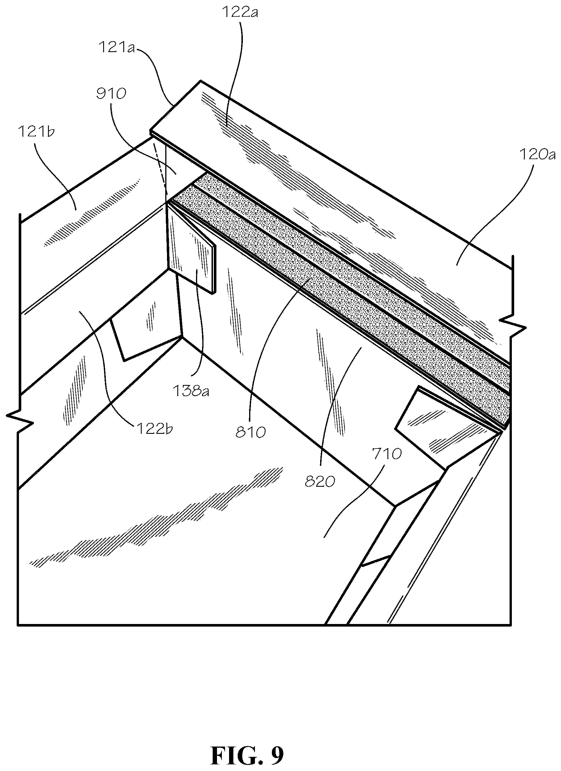
FIG. 9 is a perspective view of the partially assembled insulated box, with another upper portion of the exterior piece in the process of being folded over to overlap the top edge of the interior piece.
FIG. 10 is a perspective view of the insulated box after another upper portion of the exterior piece has been folded over to overlap the top edge of the interior piece.
FIG. 11 is a perspective view of an interior of the insulated box with the upper portions of the exterior piece folded over and overlapping side panels of the interior piece.
FIG. 12 shows a blank configured to be assembled into a box insert with vertical rails in accordance with another aspect of the present disclosure.
FIG. 13 is a perspective view of the blank of FIG. 12 with rails folded slightly upwards.
FIG. 14 is a perspective view of the insert with vertical rails inside the insulated box.
FIG. 15 is a perspective view of the insert with vertical rails in accordance with another aspect of the present disclosure.
FIG. 16 is a top view of a register configured to slide up and down along the vertical rails of the insert of FIG. 12.
FIG. 17 is a top view of a register configured to slide up and down along the vertical rails of the insert of FIG. 12 in accordance with another aspect of the present disclosure.
FIG. 18 is a perspective view of the register positioned in the insulated box as configured in FIG. 14.
FIG. 19 is a perspective view of the insulated box of FIG. 18 comprising the register and with a representation of ice packs placed over the register.
FIG. 20 is a perspective view of an assembled lid in accordance with another aspect of the present disclosure.
FIG. 21 shows a blank configured to be assembled into an inner piece of the lid of FIG. 19.
FIG. 22 shows a blank configured to be assembled into an outer piece of the lid of FIG. 19.
FIG. 23 is a perspective view of the lid of FIG. 19 in a partially assembled configuration.
FIG. 24 is a perspective view of the lid of FIG. 19 in another partially assembled configuration prior to one remaining step of pushing the inner piece of the lid into the outer piece of the lid such that tabs of the inner piece are secured by slots of the outer piece.
FIG. 25 is a perspective view of the insulated box covered by the lid.
DETAILED DESCRIPTION
The present disclosure can be understood more readily by reference to the following detailed description, examples, drawings, and claims, and the previous and following description. However, before the present devices, systems, and/or methods are disclosed and described, it is to be understood that this disclosure is not limited to the specific devices, systems, and/or methods disclosed unless otherwise specified, and, as such, can, of course, vary. It is also to be understood that the terminology used herein is for the purpose of describing particular aspects only and is not intended to be limiting.
The following description is provided as an enabling teaching of the present devices, systems, and/or methods in its best, currently known aspect. To this end, those skilled in the relevant art will recognize and appreciate that many changes can be made to the various aspects of the present devices, systems, and/or methods described herein, while still obtaining the beneficial results of the present disclosure. It will also be apparent that some of the desired benefits of the present disclosure can be obtained by selecting some of the features of the present disclosure without utilizing other features. Accordingly, those who work in the art will recognize that many modifications and adaptations to the present disclosure are possible and can even be desirable in certain circumstances and are a part of the present disclosure. Thus, the following description is provided as illustrative of the principles of the present disclosure and not in limitation thereof.
As used throughout, the singular forms "a," "an" and "the" include plural referents unless the context clearly dictates otherwise. Thus, for example, reference to "an element" can include two or more such elements unless the context indicates otherwise.
Ranges can be expressed herein as from "about" one particular value, and/or to "about" another particular value. When such a range is expressed, another aspect includes from the one particular value and/or to the other particular value. Similarly, when values are expressed as approximations, by use of the antecedent "about," it will be understood that the particular value forms another aspect. It will be further understood that the endpoints of each of the ranges are significant both in relation to the other endpoint, and independently of the other endpoint.
For purposes of the current disclosure, a material property or dimension measuring about X or substantially X on a particular measurement scale measures within a range between X plus an industry-standard upper tolerance for the specified measurement and X minus an industry-standard lower tolerance for the specified measurement. Because tolerances can vary between different materials, processes and between different models, the tolerance for a particular measurement of a particular component can fall within a range of tolerances.
As used herein, the terms "optional" or "optionally" mean that the subsequently described event or circumstance can or cannot occur, and that the description includes instances where said event or circumstance occurs and instances where it does not.
The word "or" as used herein means any one member of a particular list and also includes any combination of members of that list. Further, one should note that conditional language, such as, among others, "can," "could," "might," or "may," unless specifically stated otherwise, or otherwise understood within the context as used, is generally intended to convey that certain aspects include, while other aspects do not include, certain features, elements and/or steps. Thus, such conditional language is not generally intended to imply that features, elements and/or steps are in any way required for one or more particular aspects or that one or more particular aspects necessarily include logic for deciding, with or without user input or prompting, whether these features, elements and/or steps are included or are to be performed in any particular aspect.
Disclosed are components that can be used to perform the disclosed methods and systems. These and other components are disclosed herein, and it is understood that when combinations, subsets, interactions, groups, etc. of these components are disclosed that while specific reference of each various individual and collective combinations and permutation of these may not be explicitly disclosed, each is specifically contemplated and described herein, for all methods and systems. This applies to all aspects of this application including, but not limited to, steps in disclosed methods. Thus, if there are a variety of additional steps that can be performed it is understood that each of these additional steps can be performed with any specific aspect or combination of aspects of the disclosed methods.
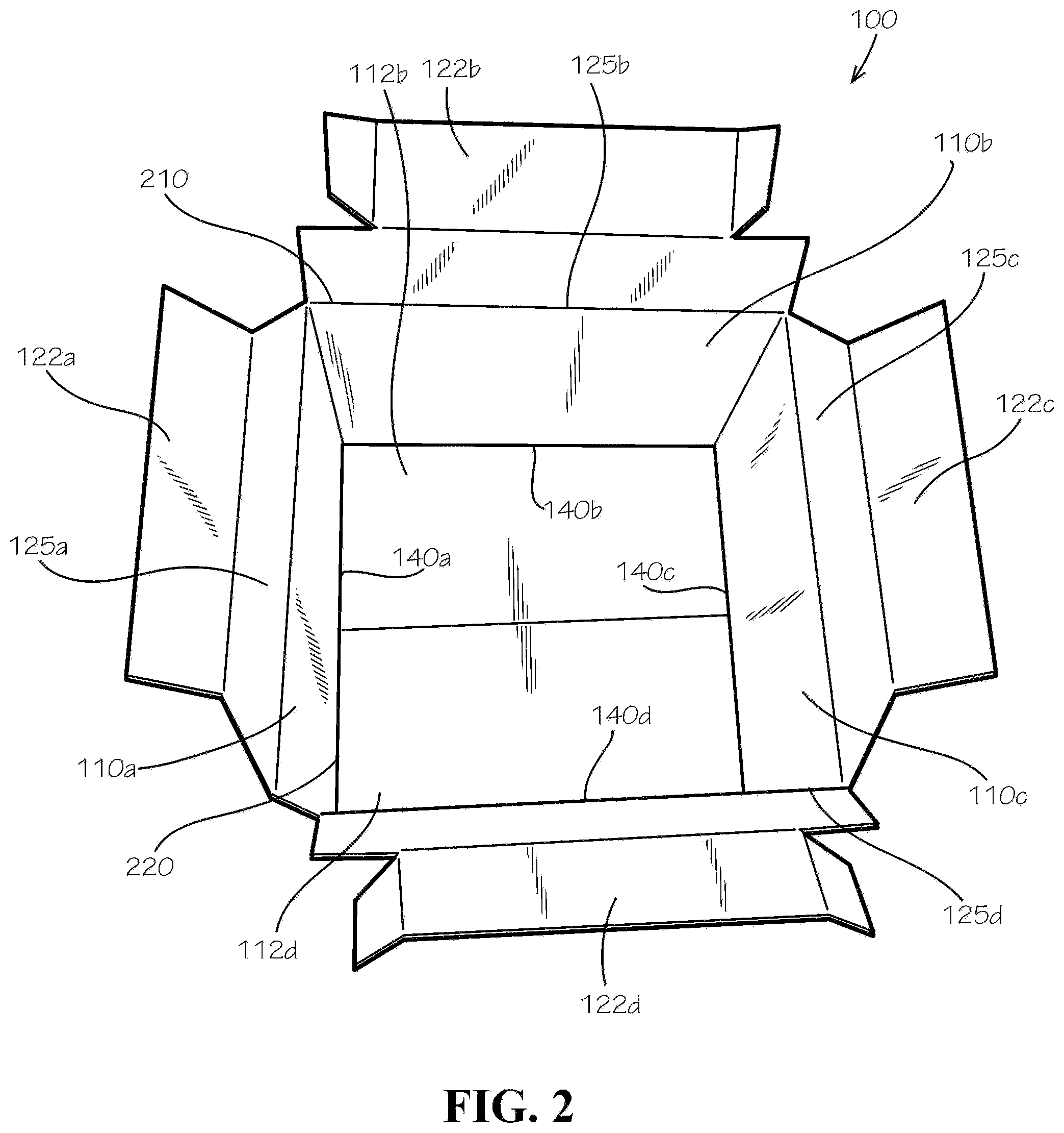
FIG. 1 shows in one exemplary aspect an exterior piece 100 of an insulated box 2400 (shown in FIG. 25) in an unassembled configuration as a blank. As shown, the exterior piece 100 can comprise four subpanels 102a,b,c,d. Each subpanel can comprise a middle portion 110a,b,c,d, an upper portion 120a,b,c,d, and a lower portion 112a,b,c,d. The middle portions 110a,b,c,d can be joined by fold lines 124a,b,c. A side strip 128 can be joined to the fourth middle portion 110d by a fold line 127. The exterior piece 100 as a blank can define a planar first exterior surface 101, with a similar planar second exterior surface (not shown) opposite from exterior surface 101.
Each middle portion 110a,b,c,d can be joined to an upper portion 120a,b,c,d by a fold line 125a,b,c,d. Each upper portion can comprise an end segment 121a,b,c,d and a connecting segment 122a,b,c,d. The end segments 121a,b,c,d can be joined to the connecting segments 122a,b,c,d by fold lines 130a,b,c,d.
The connecting segments 121a,c can be of various shapes, including rectangles, parallelograms, and trapezoids. In the current aspect, a first connecting segment 121a and a third connecting segment 121c can be trapezoidal in shape. The legs 126a,b,c,d of the first and third connecting segments 121a,c can form angles 123a,b,c,d with the fold lines 125a,b,c,d. The angles 123a,b,c,d can be about 45 degrees. A second and a fourth connecting segment 121b,d can be substantially rectangular and can comprise crease lines 132a,b,c,d.
Each end segment 122a,b,c,d can comprise a middle tab 134a,b,c,d and a side tab 136a,b,c,d. In the current aspect, the second and fourth end segments 122b,d can each comprise two side tabs 136a,b,c,d. The side tabs 136a,b,c,d can be joined to the middle tabs 134a,b,c,d by fold lines 138a,b,c,d. Each side tab can comprise a bottom edge 139a,b,c,d, and each bottom edge 139a,b,c,d can form an angle with the fold lines 138a,b,c,d. The lower portions 112a,b,c,d can be joined to the middle portions 110a,b,c,d by fold lines 140a,b,c,d.
FIG. 2 is a perspective view of the exterior piece 100 in an assembled configuration. The fold lines 140a,b,c,d joining the middle portions 110a,b,c,d to the upper portions 120a,b,c,d can form a top outside edge 210. The fold lines 140a,b,c,d joining the middle portions 110a,b,c,d to the lower portions 112a,b,c,d can form a bottom outside edge 220. The side strip 128 can be affixed to the first subpanel 102a by staples, hot melt glue, or other adhesives known in the art, or with no adhesive at all.
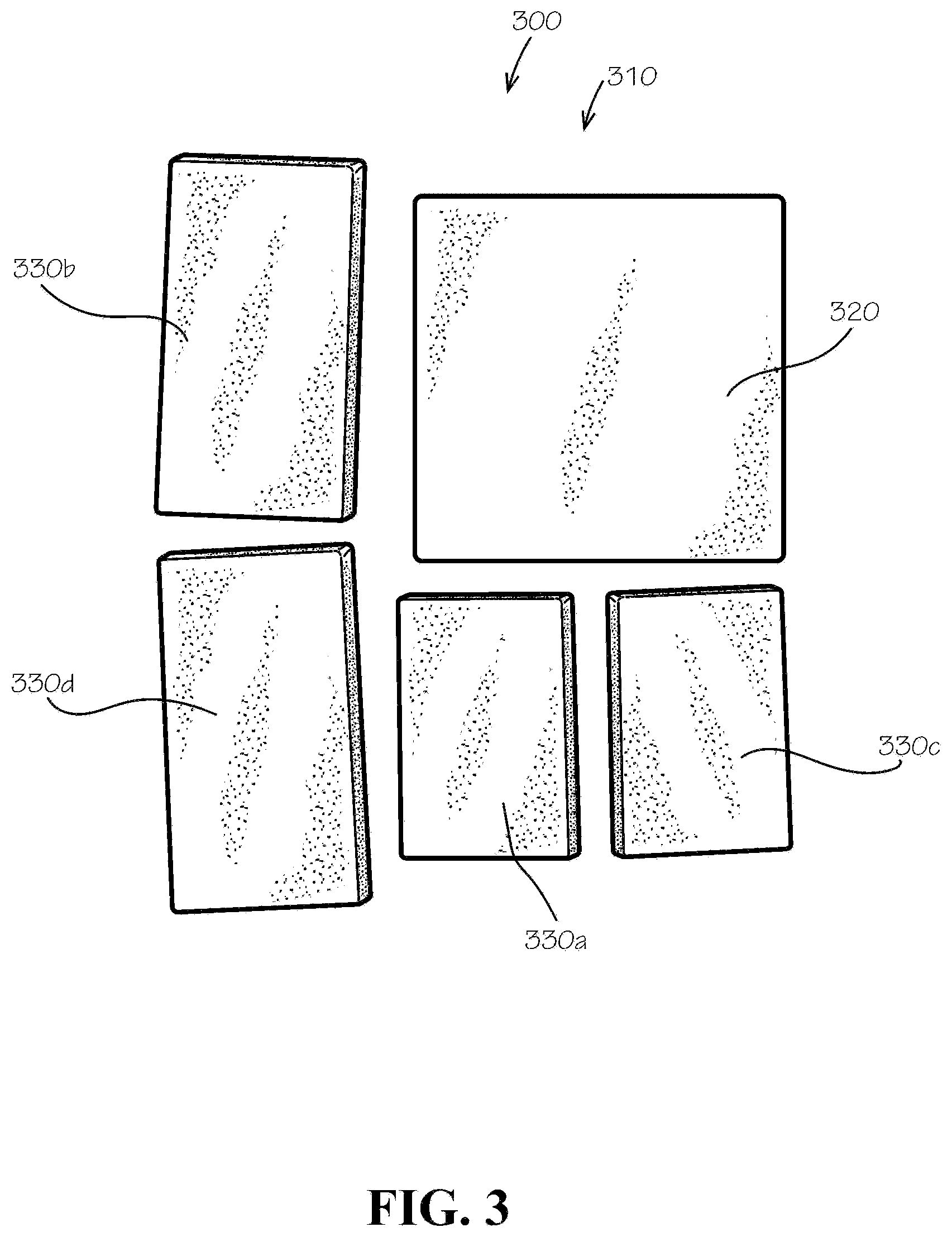
FIG. 3 shows an exemplary aspect of an insulator 300 that can be used in the insulated box 2400. The insulator 300 can form a loose fill (not shown) or another configuration known in the art. In the current aspect, the insulator 300 can comprise insulator pads 310. The insulator pads 310 can comprise a variety of materials known in the art, such as polystyrene and/or cellulose. The insulator pads 310 can comprise a bottom insulator 320 and side insulators 330a,b,c,d. The side insulators 330a,b,c,d can comprise a first, second, third, and fourth side insulator 330a,b,c,d, respectively. The first and third side insulators 330a,c can be shorter than the second and fourth side insulators 330b,d. The side insulators can also comprise a single insulator pad (not shown) extending circumferentially around the interior piece 100.
The insulator pads 310 can comprise paper or other paper fiber materials; however, in other aspects, the insulation batts can comprise cotton, foam, rubber, plastics, fiberglass, mineral wool, or any other flexible insulation material. In the present application, the insulation batts can be repulpable. In the present aspect, the insulated box 2400 can be 100% recyclable. In the present aspect, the insulated box 2400 can be single-stream recyclable wherein all materials comprised by the insulated box 2400 can be recycled by a single processing train without requiring separation of any materials or components of the insulated box 2400. In the present aspect, the insulated box 2400 can be compostable. In the present aspect, the insulated box 2400 can be repulpable. In the present aspect, the insulated box 2400 and the insulator pads 310 can be repulpable in accordance with the requirements of the Aug. 16, 2013, revision of the "Voluntary Standard For Repulping and Recycling Corrugated Fiberboard Treated to Improve Its Performance in the Presence of Water and Water Vapor" provided by the Fibre Box Association of Elk Grove Village, Ill. which is hereby incorporated in its entirety. In the present aspect, the insulated box 2400 and the insulator pads 310 can be recyclable in accordance with the requirements of the Aug. 16, 2013, revision of the "Voluntary Standard For Repulping and Recycling Corrugated Fiberboard Treated to Improve Its Performance in the Presence of Water and Water Vapor" provided by the Fibre Box Association of Elk Grove Village, Ill.
Recyclable and repulpable insulation materials are further described in U.S. patent application Ser. No. 15/677,738, filed Aug. 15, 2017, U.S. Provisional Patent Application No. 62/375,555, filed Aug. 16, 2016, U.S. Provisional Patent Application No. 62/419,894, filed Nov. 9, 2016, and U.S. Provisional Patent Application No. 62/437,365, filed Dec. 21, 2016, which are each incorporated by reference in their entirety herein.
FIG. 4 is a perspective view of the partially-assembled insulated box 2400. The insulator pads 310 are placed inside the assembled exterior piece 100. The bottom insulator 320 can cover, or proximately face, the lower portions 112a,b,c,d (not shown) of the exterior piece 100. The bottom insulator 320 can fully extend to the bottom outside edge 220. The side insulators 330a,b,c,d can alternate shorter and longer. For example, in the current aspect, the first side insulator 330a can be configured to proximately face the first middle portion 110a (not shown). Likewise, the second, third, and fourth side insulators 330bc,d, respectively, can be configured to face the corresponding numbered middle portions 110b,c,d.
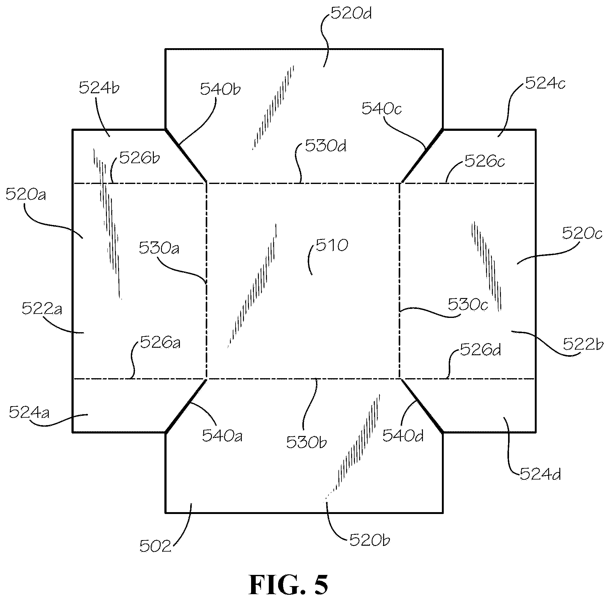
FIG. 5 shows an interior piece 500 of the insulated box 2400 in an unassembled configuration. The interior piece 500 can comprise a bottom panel 510, side panels 520a,b,c,d, and fold lines 530a,b,c,d joining the bottom panel 510 to the side panels 520a,b,c,d. An interior surface 502 faces out of the page in FIG. 5. Alternating side panels--for example, a first and a third side panel 520a,c--can comprise a middle tab 522a,b and a side tab 524a,b,c,d. The middle tabs 522a,b can be joined to the side tabs 524a,b,c,d by fold lines 526a,b,c,d. A second and a fourth side panel 520b,d can lack fold lines. The interior piece 500 can be formed from a single flat piece with side panel cuts 540a,b,c,d separating the side panels 520a,b,c,d from each other. Thus, a blank of the interior piece 500 can be configured such that each side panel 520a,b,c,d is not connected to any other side panel 520a,b,c,d, except only indirectly through the bottom panel 510. The side panel cuts 540a,b,c,d can form angles with the fold lines 526a,b,c,d, the angles being approximately 45-degrees.
FIG. 6 is a perspective view of the interior piece 500 with the fold lines 530a,b,c,d; 526a,b,c,d in a slightly bent configuration.
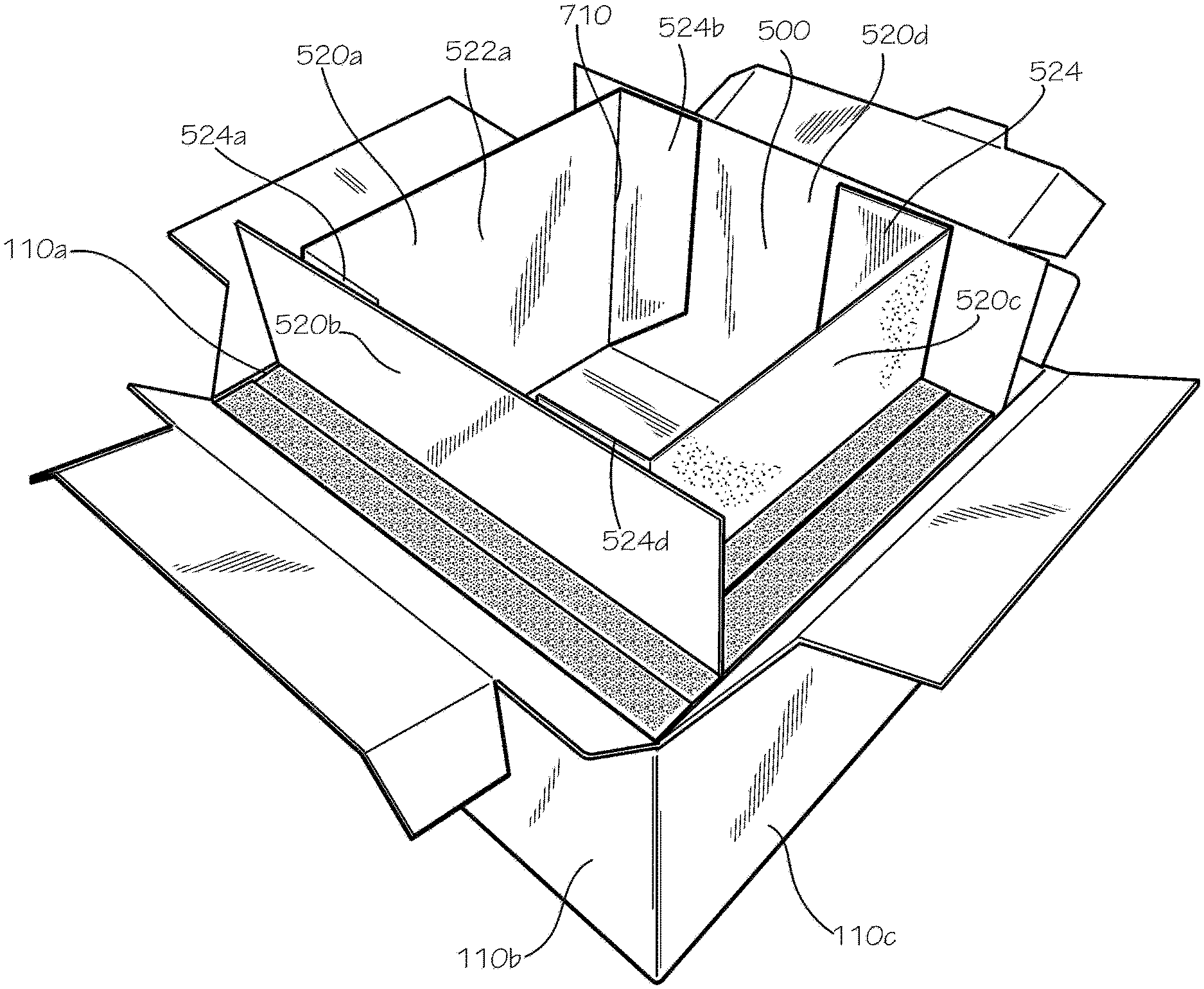
FIG. 7 is a perspective view of the interior piece 500 partially inside the partially-assembled box of FIG. 4. The middle tab 522a of the first side panel 520a of the interior piece 500 can be configured to proximately face the first middle portion 110a of the exterior piece 100. Likewise, the second, third, and fourth side panels 520b,c,d of the interior piece 500 can face the corresponding middle portions 110b,c,d of the exterior piece 100. Alternating side panels--for example, the second and fourth side panels 520b,d--can be configured to extend completely between the second and fourth middle portions 110b,d of the exterior piece 100. The side tabs 524a,b,c,d of the side panels 520a,c can be configured to fold inwards toward a cavity 710 in the insulated box 2400.
FIG. 8 is a perspective view of the partially-assembled insulated box 2400, showing a close-up of one of the exterior piece's 100 upper portions 120b (of the exterior piece 100) comprising an end segment 122b comprising a side tab 136a. The connecting segment can be configured to fold down toward the cavity 710 and cover a top edge 810 of the insulating pads 310. In other aspects (not shown) in accordance with the present disclosure, the insulator pads can be omitted, in which case the insulating properties of air left behind in a space or gap left between the interior and exterior pieces 500,100 can insulate the insulated box 2400. In yet other aspects, at least a portion of the upper portion 120a,b,c,d of the exterior piece 100--not necessarily the connecting segment 121a,c--can cover at least some portion of the space. In other words, "covering" can comprise "partially covering."
The end segment 122b can be configured to overlap or cover a top interior portion 820 of the assembled interior piece 500. In some aspects, only a portion of the top interior portion 820 may be covered by a portion of the upper portion 120a,b,c,d of the exterior piece 100. The side tab 136a can overlap the side panel adjoining the side panel overlapped by the end segment 122b, which in this aspect can be side panel 520a.
FIG. 9 is a perspective view of the partially-assembled insulated box 2400, showing the next step in assembly after FIG. 8. The upper portion 120a can be configured to fold down toward the cavity 710. The connecting segment 121a can overlap a corner 910 of the adjoining connecting segment. The end segment 122a can overlap the top interior portion 820 of the interior piece 500 and further overlap the side tab 136a of the exterior piece 100. The end segments 122a can be affixed in place by adhesives known in the art or by friction without adhesive.
FIG. 10 shows the insulated box 2400 after the step shown in FIG. 9 has been completed. The end segment 122a overlaps side panel 520a and side tab 136a of the exterior piece 100.
FIG. 11 shows another view of the insulated box 2400, particularly a close-up of end segment 122b.
FIG. 12 is a top view of a box insert 1200 with vertical rails 1220 in a flat configuration. The box insert 1200 can comprise a center segment 1210 and vertical rails 1220a,b,c,d,e,f joined by fold lines 1230a,b,c,d,e,f. The center segment 1210 can comprise cutouts 1240a,b,c,d,e,f. An edge 1242a,b,c,d,e,f of each cutout 1240a,b,c,d,e,f can be contiguous with an edge 1222a,b,c,d,e,f of each vertical rail 1220a,b,c,d,e,f, respectively. The edges 1242a,b,c,d,e,f of the cutouts 1240a,b,c,d,e,f can be curvilinear, rectilinear, or some other shape. The edges 1222a,b,c,d,e,f of the vertical rails 1220a,b,c,d,e,f can be curvilinear or rectilinear or some other shape.
FIG. 13 is a perspective view of the box insert 1200. The vertical rails 1220a,b,c,d,e,f of the box insert 1200 can be configured to bend upward along the fold lines 1230a,b,c,d,e,f. As shown in the current aspect, the fold lines 1230a,b,c,d,e,f between the vertical rails 1220a,b,c,d,e,f and the center segment 1210 can coincide with the fold lines 530a,b,c,d between the bottom panel 510 and the side panels 520a,b,c,d of the interior piece 500.
FIG. 14 is a perspective view of the box insert 1200 inside the insulated box 2400. The cutouts 1240a,b,c,d,e,f can be configured to expose regions of a bottom 1410 of the cavity 710. The box insert 1200 can be configured to allow air to flow to and from the cutouts 1240a,b,c,d,e,f and spaces 1420a,b,c,d,e,f between the vertical rails. The vertical rails 1220a,b,c,d,e,f can be configured to extend to the top interior portion 820.
FIG. 15 is a perspective view of the box insert 1200' in another exemplary aspect. In the current aspect, the vertical rails 1220a',b',c',d',e',f',g',h',i',j',k',l',m',n' can be configured to rise to a height 1510 below the top interior portion 820. The vertical rails 1220a',e',f',g',h',l',m',n' can also be configured to adjoin each other at bottom corners 1520a,b,c,d-without a space 1420 between them.
FIG. 16 is a top view of a register 1600. The register 1600 can comprise a face segment 1602. The face segment 1602 can comprise holes 1610a,b,c,d; side cutouts 1620a,b,c,d,e,f; and corner cutouts 1630a,b,c,d. The register can be cut from a single flat piece.
FIG. 17 is a top view of a register 1700' in another exemplary aspect. The register 1600' can further comprise side segments 1700a,b,c,d joined to the face segment 1602 by fold lines 1720a,b,c,d. The side segments 1700a,b,c,d can comprise fold lines 1712a,b,c,d configured to be parallel to the corresponding fold lines 1720a,b,c,d.
FIG. 18 is a perspective view of the box insert 1200 receiving the register 1600. The register 1600 and the box insert 1200 can together to form a registration system 1800. The registration system 1800 can be configured to allow the register 1600 to slide up and down the vertical rails 1220a,b,c,d,e,f along a vertical axis 1820 while the face segment 1602 is maintained in a horizontal plane 1810.
FIG. 19 is a perspective view of the registration system 1800. The side cutouts 1620a,b,c,d,e,f can be configured to receive the vertical rails 1220a,b,c,d,e,f such that the register 1600 does not tip over when an overhead weight 1910a,b is placed near an edge 1920 of the face segment 1602 or when the register 1600 is not supported under a center of mass (not shown) of the register 1600 with the overhead weight 1910a,b.
FIG. 20 is a perspective view of a lid 2000 for the insulated box 2400. The lid 2000 can comprise an inner piece 2010 and an outer piece 2020.
FIG. 21 is a top view of the inner piece 2010 of the lid 2000 in a flat, unassembled configuration. The inner piece 2010 can comprise a center segment 2110 and side segments 2120a,b,c,d joined to the center piece 2110 by fold lines 2130a,b,c,d. The fold lines 2130a,b,c,d can comprise tab cuts 2140a,b,c,d,e,f,g,h.
FIG. 22 is a top view of the outer piece 2020 of the lid 2000 in a flat, unassembled configuration. The outer piece 2020 can comprise a center segment 2210, connecting segments 2220a,b,c,d joined to the center segment 2210 by fold lines 2215a,b,c,d, and end segments 2230a,b,c,d joined to the connecting segments 2220a,b,c,d by fold lines 2225a,b,c,d. The fold lines 2225a,b,c,d can be double fold lines. Alternating segments, such as a first and a third connecting segment 2220a,c, can comprise side tabs 2222a,b,c,d joined to the connecting segments 2220a,c by fold lines 2224a,b,c,d. The fold lines 2215a,b,c,d joining the center segment 2210 to the connecting segments 2220a,b,c,d can comprise slots 2216a,b,c,d,e,f,g,h. The end segments 2230a,b,c,d can comprise tab slots 2232a,b,c,d,e,f,g,h and tabs 2234a,b,c,d,e,f,g,h.
FIG. 23 is a perspective view of a partially-assembled lid 2000. The lid 2000 can further comprise an insulator such as an insulating pad 2310 between the outer piece 2020 and the inner piece 2010. The side segments 2120a,b,c,d of the inner piece 2010 can fold toward a cavity 2320 of the outer piece 2020 in an assembled configuration. Folding the side segments 2120a,b,c,d in this way can expose the tabs 2330a,b (and others not shown) formed by the tab cuts 2140a,b,c,d,e,f,g,h. The tabs 2330a,b can be received by the tab slots 2232a,b,c,d,e,f,g,h such that the insulating pad 2310 and the inner piece 2010 are secured. The outer piece 2020 can be assembled by sandwiching the side tabs 2222a,b,c,d between neighboring connecting segments 2220b,d and end segments 2230b,d.
FIG. 24 shows another perspective view of the inner piece 2010 with its side segments 2120a,b,c,d folded into the outer piece 2020, the inner piece 2010 ready to be pushed in, locking the tabs 2330a,b,c,d,e,f of the inner piece 2010 into the tab slots 2232a,b,c,d,e,f,g,h of the outer piece 2020 (shown in FIG. 22).
FIG. 25 shows the assembled insulated box 2400 covered by the lid 2000.
The interior piece 500 and the exterior piece 100 of the insulated box 2400, the register 1600, the box insert 1200 with vertical rails 1220, and the inner piece 2010 and the outer piece 2020 of the lid 2000 can each be formed from a single piece of flat material, such as solid cardboard, corrugated cardboard, corrugated plastic, and other materials known in the art. The box insert 1200 with vertical rails 1220 can also be used with or without the register 1600 to maintain a uniform temperature and humidity level within the insulated box 2400. The spaces 1420 between the vertical rails 1220, the cutouts 1620 exposing the bottom 1410 of the cavity 710, and the holes 1610 in the register 1600 can all facilitate air flow and by diffusion and convection.
The registration system 1800 can be configured to place perishable items such as food (not shown) on one side of the register 1600 and a heat transfer element such as an ice pack (not shown) on the other. The ice pack can be place above the food to allow cooling by cold air flowing downward. Multiple registers 1600 can be used.
One should note that conditional language, such as, among others, "can," "could," "might," or "may," unless specifically stated otherwise, or otherwise understood within the context as used, is generally intended to convey that certain aspects include, while other aspects do not include, certain features, elements and/or steps. Thus, such conditional language is not generally intended to imply that features, elements and/or steps are in any way required for one or more particular aspects or that one or more particular aspects necessarily include logic for deciding, with or without user input or prompting, whether these features, elements and/or steps are included or are to be performed in any particular aspect.
It should be emphasized that the above-described aspects are merely possible examples of implementations, merely set forth for a clear understanding of the principles of the present disclosure. Any process descriptions or blocks in flow diagrams should be understood as representing modules, segments, or portions of code which include one or more executable instructions for implementing specific logical functions or steps in the process, and alternate implementations are included in which functions may not be included or executed at all, may be executed out of order from that shown or discussed, including substantially concurrently or in reverse order, depending on the functionality involved, as would be understood by those reasonably skilled in the art of the present disclosure. Many variations and modifications may be made to the above-described aspect(s) without departing substantially from the spirit and principles of the present disclosure. Further, the scope of the present disclosure is intended to cover any and all combinations and sub-combinations of all elements, features, and aspects discussed above. All such modifications and variations are intended to be included herein within the scope of the present disclosure, and all possible claims to individual aspects or combinations of elements or steps are intended to be supported by the present disclosure.
* * * * *
References
-
peri-wrap.com/insulation
-
chem-tran.com/packaging/supplies/cooliner-insulated-shipping-bags.php
-
mhpn.com/product/thermopod_mailer_envelopes_and_thermokeeper_insulated_box_liners/packaging
-
tera-pak.com
-
hotcoldbags.com/items/Cool%20Green%20Bag
-
weiku.com/products/18248504/100_Biodegradable_Packing_materials_Green_Cell_Foam_Stock_Coolers.html
-
salazarpackaging.com/custom-packaging-and-design
-
corrugated.org/wp-content/uploads/PDFs/Recycling/Vol_Std_Protocol_2013
-
coldkeepers.com/product-category/shipping
-
needlesnknowledge.blogspot.com/2017/10/tall-box-with-lid.html
-
greencellfoam.com/shipping-coolers
-
D00000
D00001
D00002
D00003
D00004
D00005
D00006
D00007
D00008
D00009
D00010
D00011
D00012

D00013
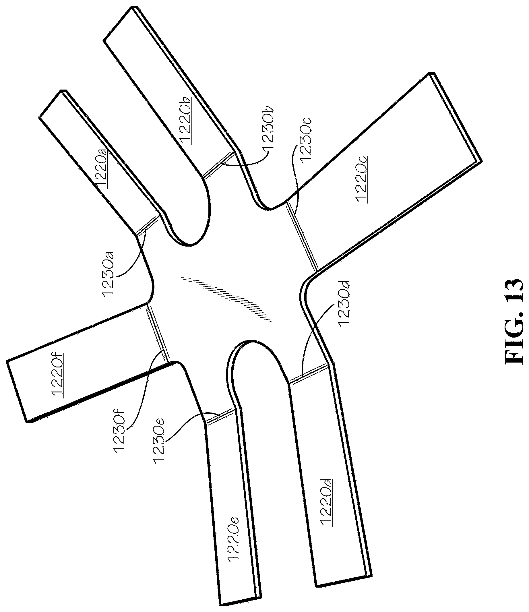
D00014
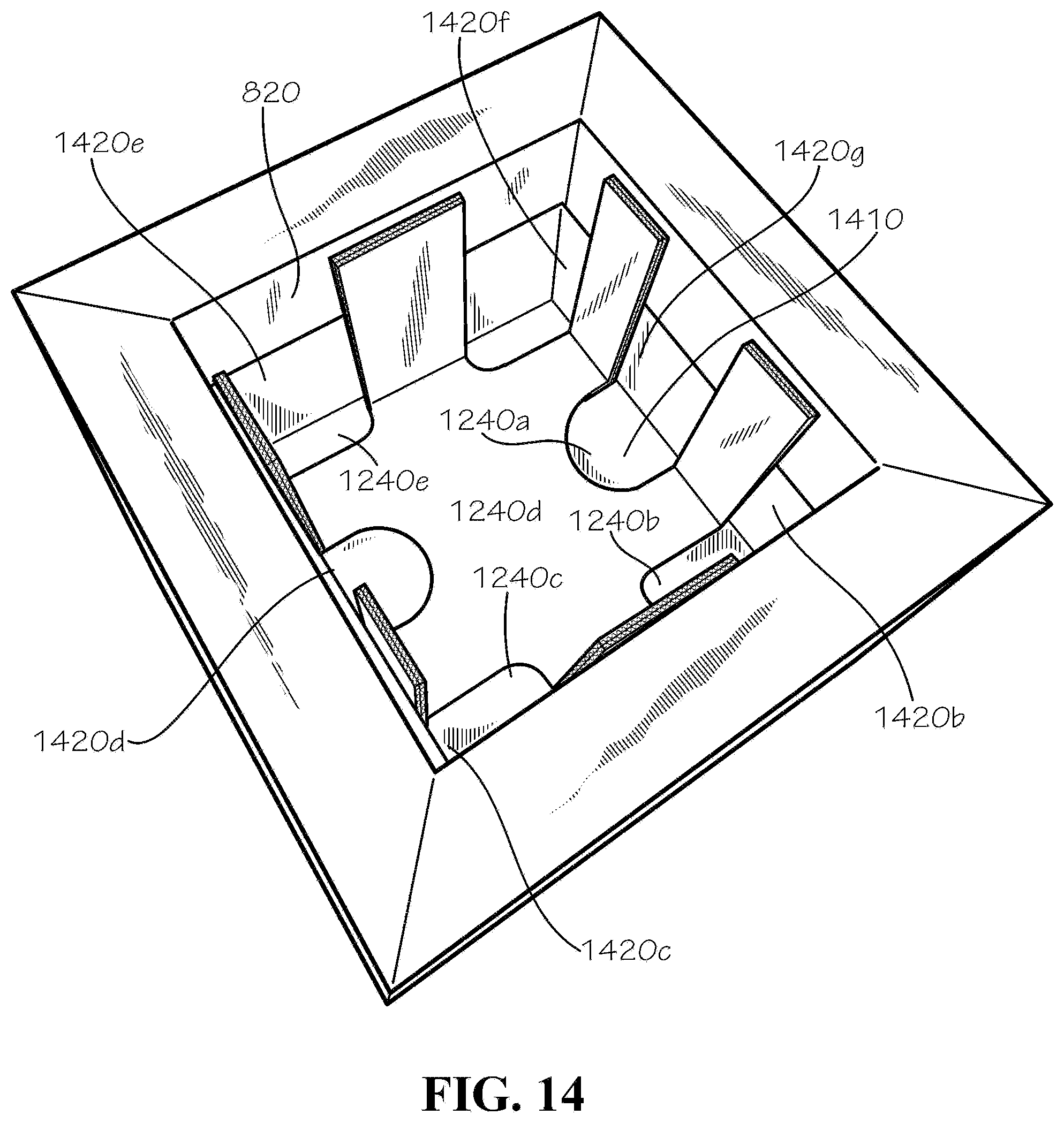
D00015

D00016

D00017

D00018
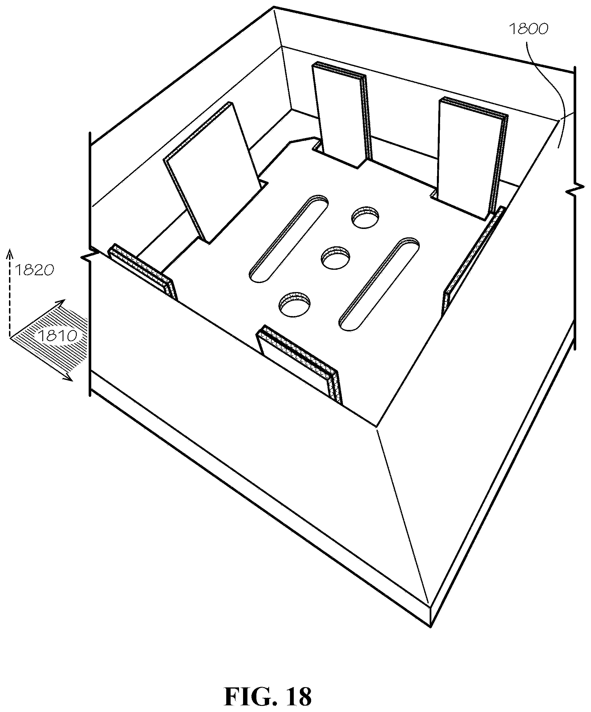
D00019
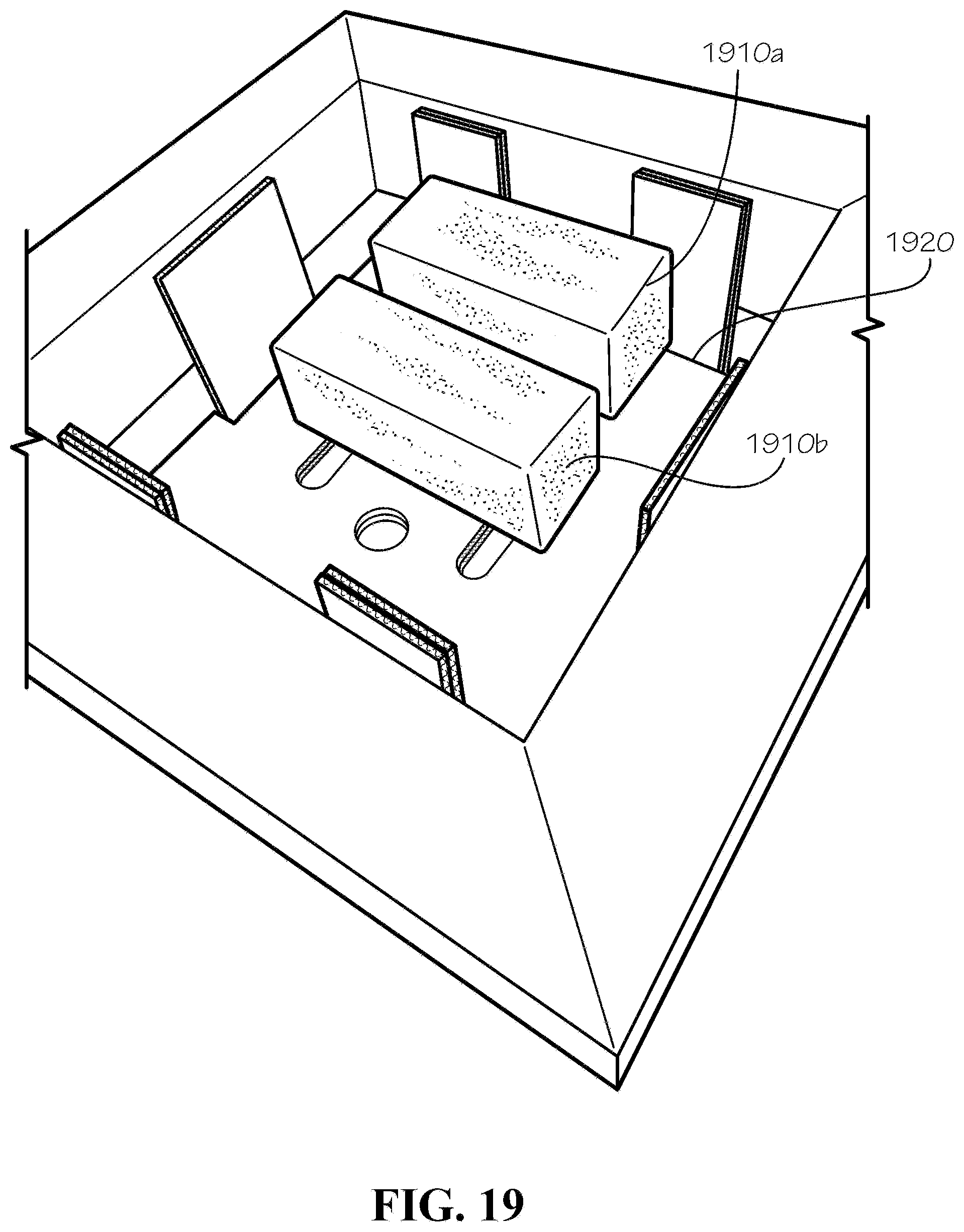
D00020

D00021

D00022

D00023

D00024
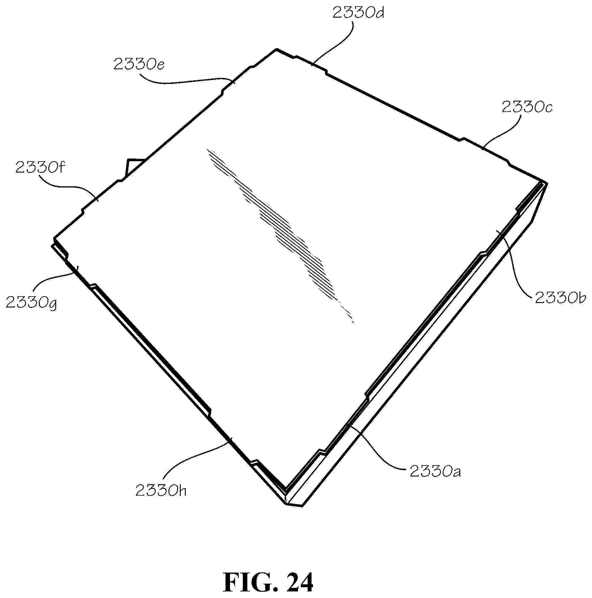
D00025
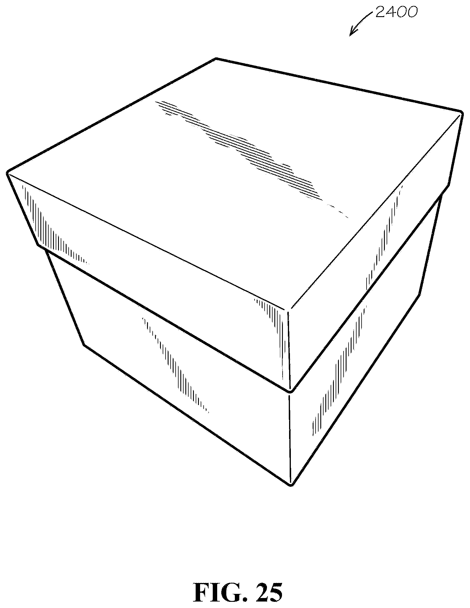
XML
uspto.report is an independent third-party trademark research tool that is not affiliated, endorsed, or sponsored by the United States Patent and Trademark Office (USPTO) or any other governmental organization. The information provided by uspto.report is based on publicly available data at the time of writing and is intended for informational purposes only.
While we strive to provide accurate and up-to-date information, we do not guarantee the accuracy, completeness, reliability, or suitability of the information displayed on this site. The use of this site is at your own risk. Any reliance you place on such information is therefore strictly at your own risk.
All official trademark data, including owner information, should be verified by visiting the official USPTO website at www.uspto.gov. This site is not intended to replace professional legal advice and should not be used as a substitute for consulting with a legal professional who is knowledgeable about trademark law.