Feeding device for poultry animals
Langfermann November 24, 2
U.S. patent number 10,842,134 [Application Number 15/713,745] was granted by the patent office on 2020-11-24 for feeding device for poultry animals. This patent grant is currently assigned to BIG DUTCHMAN INTERNATIONAL GMBH. The grantee listed for this patent is BIG DUTCHMAN INTERNATIONAL GmbH. Invention is credited to Judith Langfermann.


| United States Patent | 10,842,134 |
| Langfermann | November 24, 2020 |
Feeding device for poultry animals
Abstract
A feeding device for poultry animals having an upper feed provision element with an elongated expansion disposed so that poultry animals can reach the feed in the upper feed provision element from the access platform. The feeding device having at least one lower feed provision element disposed underneath the upper feed provision element during operation, wherein the lower feed provision element is arranged and designed so that during operation poultry animals can reach the feed in the lower feed provision element from a floor, and wherein the lower feed provision element is arranged and designed so that the lower feed provision element is supplied with feed provided in the upper feed provision element.
| Inventors: | Langfermann; Judith (Rechterfeld, DE) | ||||||||||
|---|---|---|---|---|---|---|---|---|---|---|---|
| Applicant: |
|
||||||||||
| Assignee: | BIG DUTCHMAN INTERNATIONAL GMBH
(Vechta, DE) |
||||||||||
| Family ID: | 1000005199343 | ||||||||||
| Appl. No.: | 15/713,745 | ||||||||||
| Filed: | September 25, 2017 |
Prior Publication Data
| Document Identifier | Publication Date | |
|---|---|---|
| US 20180084762 A1 | Mar 29, 2018 | |
Foreign Application Priority Data
| Sep 27, 2016 [DE] | 20 2016 105 370 U | |||
| Current U.S. Class: | 1/1 |
| Current CPC Class: | A01K 39/0106 (20130101); A01K 39/0125 (20130101); A01K 39/014 (20130101) |
| Current International Class: | A01K 39/012 (20060101); A01K 39/00 (20060101); A01K 39/014 (20060101); A01K 39/01 (20060101) |
| Field of Search: | ;119/52.1,56.2,57,57.1,57.2,57.4,57.5,58 |
References Cited [Referenced By]
U.S. Patent Documents
| 503664 | August 1893 | Jones |
| 2074383 | March 1937 | Funk |
| 2149686 | March 1939 | Rivenburgh |
| 2808029 | October 1957 | Geerlings |
| 2842096 | July 1958 | Bradfield |
| 2884899 | May 1959 | Jackes et al. |
| 2969867 | January 1961 | McClelland |
| 3102511 | September 1963 | Atcheson |
| 3139065 | June 1964 | Willauer, Jr. |
| 3145793 | August 1964 | Ray |
| 3215252 | November 1965 | Wilkes |
| 3268067 | August 1966 | Prentice et al. |
| 3319762 | May 1967 | Rose |
| 3388690 | June 1968 | Hostetler |
| 3427929 | February 1969 | Dawson |
| 3511215 | May 1970 | Myers |
| 3696584 | October 1972 | Rickard |
| 3722743 | March 1973 | Atchley |
| 3738077 | June 1973 | Leach |
| 3759368 | September 1973 | Rose et al. |
| 3770107 | November 1973 | Michelbach |
| 3811412 | May 1974 | Murto |
| 3898435 | August 1975 | Pritchard et al. |
| 3911868 | October 1975 | Brembreck |
| 3966049 | June 1976 | van den Berg |
| 3968904 | July 1976 | Neville |
| 3997388 | December 1976 | Simon |
| 4070990 | January 1978 | Swartzendruber |
| 4086998 | May 1978 | van der Schoot |
| RE29944 | March 1979 | Hyer et al. |
| 4159696 | July 1979 | Martin |
| 4199051 | April 1980 | Kimberley |
| 4216742 | August 1980 | Kirchhofer |
| 4226211 | October 1980 | Barrentine |
| 4253120 | February 1981 | Levine |
| 4345682 | August 1982 | White et al. |
| 4348988 | September 1982 | Lawson |
| 4401057 | August 1983 | Van Gilst |
| 4416218 | November 1983 | Holz |
| 4418773 | December 1983 | Finet et al. |
| 4476811 | October 1984 | Swartzendruber |
| 4527513 | July 1985 | Hart et al. |
| 4542808 | September 1985 | Lloyd, Jr. et al. |
| 4552095 | November 1985 | Segalla |
| 4575993 | March 1986 | Meyn |
| 4603657 | August 1986 | Peckskamp |
| 4675520 | June 1987 | Harrsen et al. |
| 4676197 | June 1987 | Hoover |
| 4846337 | July 1989 | Kuhlmann |
| 4863009 | September 1989 | Winkel et al. |
| 4868901 | September 1989 | Kniskern et al. |
| 4959040 | September 1990 | Gardner |
| 4995343 | February 1991 | Cole et al. |
| 5007380 | April 1991 | Badia et al. |
| 5046570 | September 1991 | Emme et al. |
| 5092274 | March 1992 | Cole |
| 5097797 | March 1992 | Van Zee et al. |
| 5101765 | April 1992 | Manfrin |
| 5101766 | April 1992 | Runion |
| 5113797 | May 1992 | van Daele |
| 5119893 | June 1992 | Jost |
| 5165514 | November 1992 | Faulkner |
| 5222589 | June 1993 | Gordon |
| 5232080 | August 1993 | van Essen et al. |
| 5275131 | January 1994 | Brake et al. |
| 5304745 | April 1994 | Rusk et al. |
| 5311839 | May 1994 | Pollock et al. |
| 5311977 | May 1994 | Dean et al. |
| 5365717 | November 1994 | McKinlay |
| 5406907 | April 1995 | Hart |
| 5435267 | July 1995 | Patterson |
| 5462017 | October 1995 | Pollock et al. |
| 5490591 | February 1996 | Faulkner |
| 5497730 | March 1996 | van Daele et al. |
| 5551822 | September 1996 | Pippin et al. |
| 5603285 | February 1997 | Kleinsasser |
| 5642688 | July 1997 | Bannier et al. |
| 5718187 | February 1998 | Pollock et al. |
| 5736682 | April 1998 | Heitmann et al. |
| 5762021 | June 1998 | Horwood et al. |
| 5765503 | June 1998 | van Daele |
| 5778821 | July 1998 | Horwood et al. |
| 5794562 | August 1998 | Hart |
| 5875733 | March 1999 | Chen |
| 5884581 | March 1999 | van Daele |
| 5927232 | July 1999 | Pollock |
| 5941193 | August 1999 | Cole |
| 5957083 | September 1999 | Cheng |
| 5964185 | October 1999 | Debonne et al. |
| 5967083 | October 1999 | Kleinsasser |
| 6050220 | April 2000 | Kimmel et al. |
| 6056109 | May 2000 | Hidai et al. |
| 6066809 | May 2000 | Campbell et al. |
| 6152078 | November 2000 | Romeu Guardia |
| 6173676 | January 2001 | Cole |
| 6211470 | April 2001 | Beran et al. |
| 6223552 | May 2001 | Zimmerbauer |
| 6317656 | November 2001 | Kira |
| 6382404 | May 2002 | Guldenfels |
| 6383068 | May 2002 | Tollett et al. |
| 6394031 | May 2002 | Moller |
| 6401936 | June 2002 | Isaacs et al. |
| 6407523 | June 2002 | Allan |
| 6412439 | July 2002 | Otto-Lubker |
| 6470826 | October 2002 | Thuline |
| 6484886 | November 2002 | Isaacs et al. |
| 6539893 | April 2003 | Otto-Lubker |
| 6625960 | September 2003 | Nambu |
| 6655317 | December 2003 | Steudler, Jr. |
| 6732851 | May 2004 | Wienken |
| 6779488 | August 2004 | Corti et al. |
| 7191895 | March 2007 | Zeitler |
| 7228817 | June 2007 | Busse |
| 7279645 | October 2007 | Inglin |
| 7552697 | June 2009 | Busse |
| 7573567 | August 2009 | Hershtik |
| 7878391 | February 2011 | Kalkhoff |
| 8033248 | October 2011 | Cole |
| 8074601 | December 2011 | Van de Ven |
| 8127916 | March 2012 | Mix |
| 8168897 | May 2012 | Sudkamp |
| 8360230 | January 2013 | Rompe |
| 8590695 | November 2013 | Moreno Rueda |
| 9907294 | March 2018 | Otto-Luebker |
| 2002/0152965 | October 2002 | Turner et al. |
| 2003/0192774 | October 2003 | Cotter et al. |
| 2004/0112713 | June 2004 | Haan et al. |
| 2005/0063513 | March 2005 | Hsieh et al. |
| 2005/0150747 | July 2005 | Menendez |
| 2005/0217963 | October 2005 | Scott |
| 2006/0039586 | February 2006 | Bickert et al. |
| 2008/0251357 | October 2008 | Kawakami |
| 2009/0020395 | January 2009 | Accettura |
| 2009/0045029 | February 2009 | Deur |
| 2010/0294624 | November 2010 | Warner |
| 2011/0062000 | March 2011 | Yamamoto |
| 2012/0160637 | June 2012 | Itoh et al. |
| 2012/0181150 | July 2012 | Damm |
| 2013/0014704 | January 2013 | Kuking |
| 2013/0092512 | April 2013 | Buschmann et al. |
| 2013/0206549 | August 2013 | Clevers et al. |
| 2013/0299317 | November 2013 | Moller |
| 2015/0164051 | June 2015 | Otto-Luebker |
| 1715083 | Aug 1982 | AU | |||
| 485 202 | Jan 1970 | CH | |||
| 204888345 | Dec 2015 | CN | |||
| 5 25 996 | Jun 1931 | DE | |||
| 1 820 785 | Aug 1960 | DE | |||
| 1 124 872 | Mar 1962 | DE | |||
| 1181482 | Nov 1964 | DE | |||
| 1 607 143 | Sep 1965 | DE | |||
| 1 406 150 | Mar 1969 | DE | |||
| 7 102 326 | Sep 1971 | DE | |||
| 2 155 120 | May 1972 | DE | |||
| 2 157 774 | May 1974 | DE | |||
| 2 313 663 | Oct 1974 | DE | |||
| 2 350 555 | Apr 1975 | DE | |||
| 2403831 | Aug 1975 | DE | |||
| 118 839 | Mar 1976 | DE | |||
| 2 612 594 | Sep 1977 | DE | |||
| 2 802 542 | Jul 1979 | DE | |||
| 3 138 748 | Apr 1983 | DE | |||
| 3 326 706 | Feb 1984 | DE | |||
| 3 332 240 | Mar 1985 | DE | |||
| 34 19 883 | Nov 1985 | DE | |||
| 3 445 429 | Jun 1986 | DE | |||
| 3 525 460 | Feb 1987 | DE | |||
| 3 607 858 | Sep 1987 | DE | |||
| 4 036 112 | Apr 1994 | DE | |||
| 43 13 456 | May 1994 | DE | |||
| 43 05 559 | Aug 1994 | DE | |||
| 4 411 776 | Oct 1995 | DE | |||
| 195 46 626 | Jun 1997 | DE | |||
| 196 07 258 | Aug 1997 | DE | |||
| 197 07 155 | Aug 1997 | DE | |||
| 198 51 793 | Nov 1998 | DE | |||
| 198 07 231 | Sep 1999 | DE | |||
| 199 12 821 | Nov 1999 | DE | |||
| 199 06 916 | Aug 2000 | DE | |||
| 19948057 | Apr 2001 | DE | |||
| 101 06 206 | Aug 2002 | DE | |||
| 101 64 100 | Apr 2003 | DE | |||
| 101 64 122 | May 2003 | DE | |||
| 203 15 118 | Feb 2004 | DE | |||
| 20 2004 003 194 | Mar 2004 | DE | |||
| 102 48 875 | Apr 2004 | DE | |||
| 102 55 072 | Jun 2004 | DE | |||
| 202004003194 | Jun 2004 | DE | |||
| 699 24 866 | Mar 2006 | DE | |||
| 2006 003 445 | Aug 2007 | DE | |||
| 2006 004 894 | Aug 2007 | DE | |||
| 20 2007 008 362 | Sep 2007 | DE | |||
| 20 2007 009 477 | Sep 2007 | DE | |||
| 20 2006 007 875 | Oct 2007 | DE | |||
| 20 2008 003 498 | Oct 2008 | DE | |||
| 10 2009 055 952 | Jun 2011 | DE | |||
| 20 2010 016 688 | May 2012 | DE | |||
| 20 2012 004 330 | Jul 2012 | DE | |||
| 20 2012 004 008 | Aug 2012 | DE | |||
| 10 2012 003987 | Aug 2013 | DE | |||
| 20 2012 010 170 | Mar 2014 | DE | |||
| 20 2012 010 693 | Mar 2014 | DE | |||
| 20 2012 010 694 | Mar 2014 | DE | |||
| 20 2014 000 575 | Apr 2014 | DE | |||
| 20 2013 001 238 | Jul 2014 | DE | |||
| 202013010980 | Mar 2015 | DE | |||
| 20 2013 010 980 | Apr 2015 | DE | |||
| 20 2015 102 303 | Jul 2015 | DE | |||
| 2010 70867 | Feb 2011 | EA | |||
| 0 287 874 | Oct 1988 | EP | |||
| 0 105 571 | Jun 1989 | EP | |||
| 0 387 242 | Sep 1990 | EP | |||
| 0 414 487 | Feb 1991 | EP | |||
| 0 421 553 | Apr 1991 | EP | |||
| 0 718 218 | Jun 1996 | EP | |||
| 0 891 704 | Jan 1999 | EP | |||
| 0 892 254 | Jan 1999 | EP | |||
| 1 077 026 | Feb 2001 | EP | |||
| 1 145 631 | Oct 2001 | EP | |||
| 1 306 326 | May 2003 | EP | |||
| 0 892 254 | Sep 2003 | EP | |||
| 1 570 732 | Sep 2005 | EP | |||
| 1 856 971 | May 2007 | EP | |||
| 2 134 164 | Sep 2008 | EP | |||
| 1 671 901 | Dec 2008 | EP | |||
| 2 003 412 | Dec 2008 | EP | |||
| 2 045 198 | Apr 2009 | EP | |||
| 2 377 787 | Oct 2011 | EP | |||
| 2 850 927 | Mar 2015 | EP | |||
| 2449667 | Mar 2014 | ES | |||
| 1129736 | Jan 1957 | FR | |||
| 2030824 | Nov 1970 | FR | |||
| 2322809 | Apr 1977 | FR | |||
| 2483652 | Dec 1981 | FR | |||
| 2780247 | Dec 1999 | FR | |||
| 856296 | Dec 1960 | GB | |||
| 1 021 571 | Mar 1966 | GB | |||
| 1 022 509 | Mar 1966 | GB | |||
| 1022509 | Mar 1966 | GB | |||
| 1 237 284 | Aug 1967 | GB | |||
| 1 406 164 | Apr 1973 | GB | |||
| 2 047 649 | Dec 1980 | GB | |||
| 2 080 663 | Feb 1982 | GB | |||
| 2 086 593 | May 1982 | GB | |||
| 2 125 756 | Aug 1982 | GB | |||
| 2 226 130 | Jun 1990 | GB | |||
| S4832580 | Apr 1973 | JP | |||
| S 5889508 | May 1983 | JP | |||
| 11079345 | Mar 1999 | JP | |||
| 11139526 | May 1999 | JP | |||
| 2000-235005 | Aug 2000 | JP | |||
| 2001-27612 | Jan 2001 | JP | |||
| 2001-287710 | Oct 2001 | JP | |||
| 2003-346124 | Dec 2003 | JP | |||
| 2007-175027 | Dec 2007 | JP | |||
| 8002232 | Nov 1981 | NL | |||
| 9400025 | Aug 1995 | NL | |||
| 1037320 | Sep 2009 | NL | |||
| 2129303 | Apr 1999 | RU | |||
| 1483470 | May 1989 | SU | |||
| 9743733 | Nov 1997 | WO | |||
| 2004004319 | Jan 2004 | WO | |||
| 2005 109111 | Nov 2005 | WO | |||
| 2009 092130 | Jul 2009 | WO | |||
| 2011 136 644 | Nov 2011 | WO | |||
| 2012045622 | Apr 2012 | WO | |||
Attorney, Agent or Firm: Price Heneveld LLP
Claims
The invention claimed is:
1. A feeding device for poultry animals, comprising: an upper feed provision element comprising an elongated expansion; at least one access platform disposed so that poultry animals can reach the feed in the upper feed provision element from the access platform; and at least one lower feed provision element disposed underneath the upper feed provision element during operation, wherein the lower feed provision element is disposed so that, during operation, poultry animals can reach the feed in the lower feed provision element from a floor; wherein the lower feed provision element is disposed so that the lower feed provision element is supplied with feed provided in the upper feed provision element.
2. The feeding device of claim 1, wherein the access platform comprises a perch or a grate.
3. The feeding device of claim 1, wherein the upper feed provision element is designed as a feeding trough.
4. The feeding device of claim 1, wherein the lower feed provision element is designed as a feed pan.
5. The feeding device of claim 1, wherein the lower feed provision element is connected to the upper feed provision element through a feed line.
6. The feeding device of claim 5, wherein at least one section of the feeding line comprises a hollow tube.
7. The feeding device of claim 1, wherein a bottom of the upper feed provision element proximate the lower feed provision element comprises an opening.
8. The feeding device of claim 1, wherein a transversal to the elongated extension comprises an essentially horizontal width of the upper feed provision element is maximally 50% larger or smaller than a width of the lower feed provision element in the same direction.
9. The feeding device of claim 1, wherein the upper feed provision element comprises a conveyor system to transport feed.
10. The feeding device of claim 9, wherein the conveyor system extends along the elongated extension.
11. The feeding device of claim 9, wherein the conveyor system comprises a conveyor chain or conveyor spiral.
12. The feeding device of claim 1, further comprising two or multiple access platforms for poultry animals.
13. The feeding device of claim 12, wherein the multiple access platforms comprise perches.
14. The feeding device of claim 1, further comprising two or multiple lower feed provision elements, during operation, disposed underneath the upper feed provision element.
15. A method for feeding poultry animals, comprising the step of: providing a feeding device for poultry animals, the feeding device further comprising: an upper feed provision element with an elongated expansion; at least one access platform disposed so that poultry animals can reach the feed in the upper feed provision element from the access platform; and at least one lower feed provision element arranged underneath the upper feed provision element during operation, wherein the lower feed provision element disposed so that, during operation, poultry animals can reach the feed in the lower feed provision element from a floor, wherein the lower feed provision element is disposed so that the lower feed provision element is supplied with feed provided in the upper feed provision element; and further comprising the step of providing a supply of feed in the upper feed provision element; wherein the supply of feed moves from the upper feed provision element to the lower feed provision element.
16. Use of a feeding device pursuant to claim 15 to feed poultry animals.
Description
CROSS-REFERENCE TO FOREIGN PRIORITY APPLICATION
The present application claims the benefit under 35 U.S.C. .sctn. 119(b) of German Application No. DE 20 2016 105370.6 filed Sep. 27, 2016, titled "Feeding Device for Poulty Animals."
FIELD OF THE INVENTION
The invention relates to a feeding device to poultry animals and a process for feeding poultry animals.
BACKGROUND OF THE INVENTION
Feeding devices for poultry animals are known. The disadvantage of existing feeding devices is that space for the feeding device is limited and/or not easily accessible. Another disadvantage is that the feed is continuously soiled.
Therefore, it is an object of the existing invention to provide a feeding device for poultry animals and a process for feeding poultry animals that reduces or avoids one or more of the stated disadvantages. It is, in particular, an object of the present invention to provide a feeding device for poultry animals and a process for feeding poultry animals that facilitates the accessibility of the feed and/or allows improved feeding and/or reduction of soiling of the feed.
This object is solved by a feeding device for poultry animals comprised of an upper feed provision element with an elongated extension, at least one access platform, for example, a perch or grate, disposed so that poultry animals can reach the feed in the upper feed provision element from the access platform, at least one lower feed provision element disposed underneath the upper feed provision element during operation, wherein the lower feed provision element is disposed so that, during operation, poultry animals from the floor can reach the feed in the lower feed provision element, and wherein the lower feed provision element is disposed so that the lower feed provision element is supplied with feed provided in the upper feed provision element.
SUMMARY OF THE INVENTION
The feeding device for poultry animals comprises an upper feed provision element with an elongated extension, which during operation is essentially aligned horizontally. The upper feed provision element is preferably open to the top and arranged and designed so that poultry animals can consume the feed from the upper feed provision element.
Pursuant to the invention, an access platform is also provided from which poultry animals can reach the feed in the upper feed provision element. During operation, the upper feed provision element is preferably arranged at a distance from a floor, for example, a stable or aviary floor. This distance is preferably spaced so that poultry animals from the floor cannot reach the feed in the upper feed provision element but must first step onto the access platform to do so. Preferably, the access platform is also arranged at a distance from the floor. The access platform, for example, may be in the shape of a perch or a grate. Furthermore, an elongated extension of the access platform parallel to the elongated extension of the upper feed provision element is preferred. The access platform is preferably arranged above and/or laterally from the upper feed provision element.
Furthermore, during operation, a lower feed provision element is arranged underneath the upper feed provision element. This lower feed provision element may also feature an elongated extension, but may be designed significantly shorter in the direction of the elongated extension of the upper feed provision element.
The lower feed provision element is preferably open to the top and is arranged and designed so that during operation poultry animals can consume the feed from the lower feed provision element from the floor.
The feed in the lower feed provision element is provided by supplying the lower feed provision element from the upper feed provision element. This means, in particular, that feed provided in the lower feed provision element has initially been added to the upper feed provision element and from there reaches the lower feed provision element.
The feeding device pursuant to the invention has several advantages. On the one hand, the feeding device pursuant to the invention guarantees improved accessibility of the feed. In particular, a higher number of poultry animals can simultaneously consume feed, because additional poultry animals have access to the upper feed provision element due to the access platform, even if access to the lower feed provision element is already occupied by poultry animals located on the floor.
Furthermore, arranging the lower feed provision element during operation underneath the upper feed provision element protects the feed located in the lower feed provision element against soiling, because the upper feed provision element prevents or at least obstructs the ingress of soil into the lower feed provision element.
On the other hand, supplying the lower feed provision element from the upper feed provision element constitutes an increase of the feed offer to various feed provision elements without the need of providing additional or separate feed conveyor or feed supply systems for the lower feed provision element.
The upper feed provision element is preferably designed as a feeding trough. The lower feed provision element is furthermore preferably designed as a feed pan. A feed pan can essentially have a circular or oval horizontal diameter. The feed pan can, for example, be plate-shaped or bowl-shaped.
A preferred embodiment further provides that the lower feed provision element during operation is arranged at a height above a floor of an animal house at which poultry animals from the floor can reach feed supplied in the lower feed provision element.
In particular it is preferred that the upper feed provision element as well as the lower feed provision element are arranged at a distance from a floor of an animal house. The feeding device is preferably suspended from a ceiling or support structure in the animal house. In this manner, the floor may remain free and may, for example, be filled with litter.
A preferred embodiment provides that the lower feed provision element is connected to the upper feed provision element through a feed line. This feed line preferably serves to supply the lower feed provision element. The feed line is preferably arranged and designed to support the lower feed provision element and is attached to the upper feed provision element.
It is, in particular, preferred that the lower feed provision element is supplied from the upper feed provision element due to gravity. Furthermore, it is preferred that a connection to supply the lower feed provision element from the upper feed provision element can be opened or closed, for example by moving a locking element from an open to a closed position. Furthermore, it is preferably provided that at least one section of the feed line is designed as a hollow tube, in particular essentially as a vertically aligned downpipe.
It is, in particular, preferable that a bottom of the upper feed provision element features an opening in the area of the lower feed provision element. Furthermore, the opening in the bottom of the upper feed provision element is preferably connected to the feed line. In this manner, the lower feed provision element can be supplied particularly easily from the upper feed provision element due to gravity.
In another embodiment, a transversal to the elongated extension during operation comprises an essentially horizontal width of the upper feed provision element that is maximally 50% greater or smaller than a width of the lower feed provision element in the same direction. In particular it is preferred that a transversal to the elongated extension during operation comprises an essentially horizontal width of the upper feed provision element that is maximally 40%, and maximally 30%, and maximally 20%, or maximally 10% greater or smaller than a width of the lower feed provision element in the same direction. Limiting the different widths between the upper feed provision element and the lower feed provision element can in particular have a positive effect on protecting the feed in the lower feed provision element from soiling.
Another preferred embodiment provides that the upper feed provision element features a conveyor system to transport feed, in particular along the elongated extension. The transport system is preferably designed as a conveyor chain or conveyor spiral.
Furthermore, it is preferred that the feeding device comprises two or multiple access platforms, for example, perches or grates, for poultry animals. An access platform during operation is preferably arranged above the upper feed provision element. Preferably, an access platform during operation is essentially arranged at the height of the lower feed provision element. In particular, it is preferred that one access platform each is arranged on both longitudinal sides of the upper feed provision element. Furthermore, it is preferred that an elongated extension of the two or multiple access platforms is in a parallel direction to the elongated extension of the upper feed provision element.
In another preferred embodiment, the feeding device comprises two or multiple lower feed provision elements arranged underneath the upper feed provision element during operation. Preferably, all or some of these additional lower feed provision elements are designed as described herein. In particular, all lower feed provision elements could be designed in the same manner. However, it is also possible that individual lower feed provision elements or groups of lower feed provision elements differ from the others.
Pursuant to another aspect, the object stated above is solved by a process for feeding poultry animals, comprising: provision of a feeding device described herein; provision of feed in the upper feed provision element; supplying feed from the upper feed provision element to the lower feed provision element.
Pursuant to another aspect, the object stated above is solved by using one of the feeding devices described above to feed poultry animals.
Concerning the advantages, design variances, and design details of these further aspects of the invention and its possible embodiments, reference is made to the description provided herein of the respective features, as will be understood and appreciated by those skilled in the art upon studying the following specification, claims, and appended drawings concerning the relevant features of the feeding device.
BRIEF DESCRIPTION OF THE DRAWINGS
Preferential embodiments of the invention are described by way of example in the enclosed figures. The following is shown:
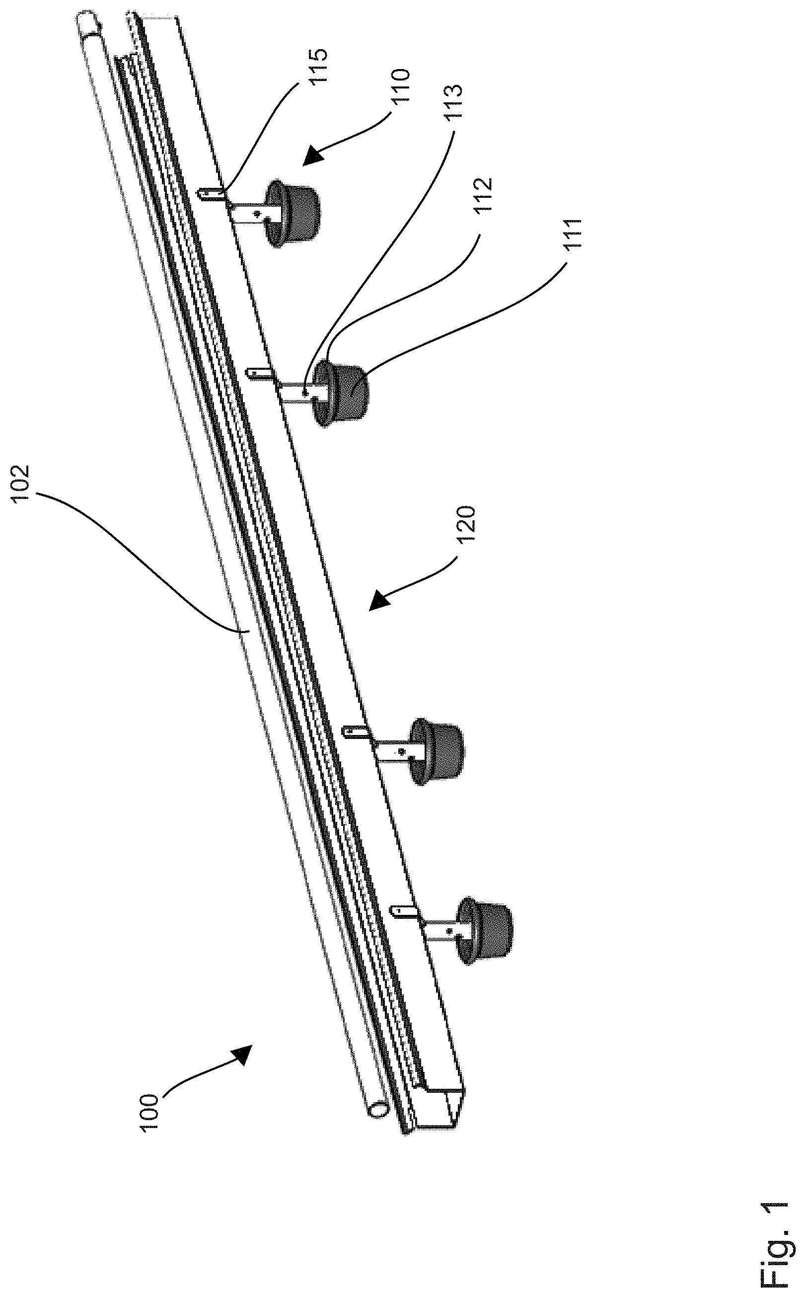
FIG. 1 is a three-dimensional view of an exemplary embodiment of a feeding device for poultry animals pursuant to the invention; and
FIG. 2 is a cross section of another exemplary embodiment of a feeding device for poultry animals pursuant to the invention.
DETAILED DESCRIPTION OF THE PREFERRED EMBODIMENTS
As referenced in the Figures, the same reference numerals may be used herein to refer to the same parameters and components or their similar modifications and alternatives. For purposes of description herein, the terms "upper," "lower," "right," "left," "rear," "front," "vertical," "horizontal," and derivatives thereof shall relate to the present disclosure as oriented in FIG. 1. However, it is to be understood that the present disclosure may assume various alternative orientations and step sequences, except where expressly specified to the contrary. It is also to be understood that the specific devices and processes illustrated in the attached drawings, and described in the following specification, are simply exemplary embodiments of the inventive concepts defined in the appended claims. Hence, specific dimensions and other physical characteristics relating to the embodiments disclosed herein are not to be considered as limiting, unless the claims expressly state otherwise. The drawings referenced herein are schematic and associated views thereof are not necessarily drawn to scale. Equal or essentially functionally similar elements have the same reference numbers in the Figures.
FIGS. 1 and 2 show a feeding device 100 for poultry animals 200 (only shown in FIG. 2) with an upper feed provision element designed as a feeding trough 120, essentially aligned horizontally with an elongated extension during operation. Underneath the feeding trough, FIG. 1 shows four lower feed provision elements (in the cross section in FIG. 2, only one lower feed provision element is discernible), which are designed as feed pans 110 in the form of bowls 111. The Figures only show a section of a feeding device 100. Fewer or significantly more than four feed pans 110 may be arranged in a feeding device 100. Furthermore, other configurations of the upper feed provision element and the lower feed provision element may be provided for.
The feeding trough 120 as well as the feed pans 110 are open to the top and are arranged and designed so that poultry animals 200 can consume the feed from them. The feeding trough 120 features an upper edge 122 widened toward the outside, and an interior space 121 in which the feed is provided. The feed may, for example, be provided by a conveyor spiral or a conveyor chain (not shown) in feeding trough 120. The feed pans feature an upper edge 112 widened slightly to the outside and an interior space in which the feed is provided. The feed lines 113 are widened in an upper area 114 and attached to feeding trough 120 with attachment elements 115. The feed pans 110 in turn are attached to the feed lines 113, preferably in a way that feed from the feed lines 113 can reach the feed pans 110. In this manner, the feed lines 113 support the feed pans 110 and suspend them from feeding trough 120.
The feed pans 110 are arranged and designed so that they are supplied with feed provided in feeding trough 120. For this, one feed line 113 essentially designed as a vertical downpipe is provided per feed pan 110. The bottom 123 of feeding trough 120 in the area of the feed lines 113 features openings 124, through which feed provided in feeding trough 120 can reach the feed pans 110 essentially due to gravity.
As is, in particular, discernible in FIG. 2, the feed pans 110 and the feeding trough 120 during operation are at a distance from the floor 300 of the animal house, here designed as a wire floor. Here, the feed pans 110 are arranged at a height above a floor 300 in which poultry animals 200 from the floor 300 can reach feed provided for in feed pans 110.
An essentially horizontal width of the feeding trough 120 aligned diagonally to the elongated extension during operation is maximally 20% smaller, preferably maximally 10% smaller than a width of feed pans 110 in the same direction.
The feeding device 100 features three access platforms in the form of perches 102, 103, 104 for poultry animals 200. A perch 102 during operation is arranged above the feeding trough 120 and is shown in both FIGS. 1 and 2. During operation, two additional perches 103, 104 (shown only in FIG. 2) are essentially arranged at the height of the feed pans 110. One perch 103, 104 each is arranged on both longitudinal sides of the main feeding trough 120. An elongated expansion of the three perches 102, 103, 104 is arranged parallel to the elongated extension of feeding trough 120.
The feeding device 100 has the advantage that a greater number of poultry animals 200 can reach the feed simultaneously. While poultry animals 200 located on the floor 300 can consume feed from the feeding pans 110 and occupy access to these feeding pans 110, additional poultry animals 200 located on the access platforms in the form of perches 102, 103, 104 can simultaneously access feed from feeding trough 120. In this manner, improved accessibility of the feed by a multitude of animals is guaranteed. The feeding device 100 furthermore has the advantage that additional feeding stations in the form of feed pans 110 are provided underneath feeding trough 120, which are supplied from feeding trough 120. Thus, in particular in case of a lack or scarcity of feeding space in a livestock facility, additional feed can quickly and easily be provided. The location of feed pans 110 under feeding trough 120 has the advantage that the feed on the lower level is not soiled by poultry animals sitting above it or soiling is reduced.
Furthermore, this arrangement facilitates improved activity of poultry. Even if a poultry animal stands on the upper access platform and eats on the upper feed provision element, the lower feed provision elements remain accessible. The lower feed provision elements are an excellent option specifically also for poultry animals with difficulties reaching an access platform or difficulties, e.g., sitting on a perch, because they are also accessible from the floor and it is therefore not necessary to reach an access platform or sit on a perch. The upper feed provision element as well as the lower feed provision element(s) therefore are permanently and simultaneously accessible for poultry animals. Therefore, feed can be offered on two levels while loading feed is possible via a joint conveyor system.
It will be understood by one having ordinary skill in the art that construction of the described present disclosure and other components is not limited to any specific material. Other exemplary embodiments of the disclosure disclosed herein may be formed from a wide variety of materials, unless described otherwise herein.
For purposes of this disclosure, the term "operably coupled" (in all of its forms, couple, coupling, coupled, etc.) generally means the joining of two components (electrical or mechanical) directly or indirectly to one another. Such joining may be stationary in nature or movable in nature. Such joining may be achieved with the two components (electrical or mechanical) and any additional intermediate members being integrally formed as a single unitary body with one another or with the two components. Such joining may be permanent in nature or may be removable or releasable in nature unless otherwise stated.
For purposes of this disclosure, the term "operably connected" (in all of its forms, connect, connecting, connected, etc.) generally means that one component functions with respect to another component, even if there are other components located between the first and second component, and the term "operable" defines a functional relationship between components.
It is also important to note that the construction and arrangement of the elements of the present disclosure as shown in the exemplary embodiments is illustrative only. Although only a few embodiments of the present innovations have been described in detail in this disclosure, those skilled in the art who review this disclosure will readily appreciate that many modifications are possible, e.g., variations in sizes, dimensions, structures, shapes and proportions of the various elements, values of parameters, mounting arrangements, use of materials, colors, orientations, etc. without materially departing from the novel teachings and advantages of the subject matter recited. For example, elements shown as integrally formed may be constructed of multiple parts or elements shown in multiple parts may be integrally formed, the operation of the interfaces may be reversed or otherwise varied, the length or width of the structures and/or members or connector or other elements of the system may be varied, the nature or number of adjustment positions provided between the elements may be varied. It should be noted that the elements and/or assemblies of the system may be constructed from any of the wide variety of materials that provide sufficient strength or durability, in any of the wide variety of colors, textures, and combinations. Accordingly, all such modifications are intended to be included within the scope of the present innovations. Other substitutions, modifications, changes, and omissions may be made in the design, operating conditions, and arrangement of the desired and other exemplary embodiments without departing from the spirit of the present innovations.
It will be understood that any described processes or steps within described processes may be combined with other disclosed processes or steps to form structures within the scope of the present disclosure. The exemplary structures and processes disclosed herein are for illustrative purposes and are not to be construed as limiting.
It is to be understood that variations and modifications can be made on the afore-mentioned structure and method without departing from the concepts of the present disclosure, and further it is to be understood that such concepts are intended to be covered by the following claims unless these claims by their language expressly state otherwise.
* * * * *
D00000
D00001
D00002
XML
uspto.report is an independent third-party trademark research tool that is not affiliated, endorsed, or sponsored by the United States Patent and Trademark Office (USPTO) or any other governmental organization. The information provided by uspto.report is based on publicly available data at the time of writing and is intended for informational purposes only.
While we strive to provide accurate and up-to-date information, we do not guarantee the accuracy, completeness, reliability, or suitability of the information displayed on this site. The use of this site is at your own risk. Any reliance you place on such information is therefore strictly at your own risk.
All official trademark data, including owner information, should be verified by visiting the official USPTO website at www.uspto.gov. This site is not intended to replace professional legal advice and should not be used as a substitute for consulting with a legal professional who is knowledgeable about trademark law.