Grid assembly for a plate-shaped battery electrode of an electrochemical accumulator battery
Staffeldt , et al. November 17, 2
U.S. patent number 10,840,515 [Application Number 16/173,906] was granted by the patent office on 2020-11-17 for grid assembly for a plate-shaped battery electrode of an electrochemical accumulator battery. This patent grant is currently assigned to Clarios Germany GmbH & Co. KGAA. The grantee listed for this patent is Johnson Controls Autobatterie GmbH & Co. KGaA. Invention is credited to Bernd Ide, Ingo Koch, Armin Staffeldt, Ornwasa Traisigkhachol.


| United States Patent | 10,840,515 |
| Staffeldt , et al. | November 17, 2020 |
Grid assembly for a plate-shaped battery electrode of an electrochemical accumulator battery
Abstract
The invention relates to a grid arrangement for a plate-shaped battery electrode of an electrochemical accumulator having a frame and a grid arranged thereon, wherein the frame comprises at least one upper frame element having a connecting lug of the battery electrode disposed on its side facing away from the grid, and wherein the grid is at least formed by horizontal bars, which are bars extending substantially horizontally, and vertical bars, which are bars extending substantially vertically, wherein at least some of the vertical bars are arranged at different angles to one another in the shape of a fan. The invention further relates to an accumulator.
| Inventors: | Staffeldt; Armin (Lauenbruck, DE), Koch; Ingo (Hameln, DE), Ide; Bernd (Hannover, DE), Traisigkhachol; Ornwasa (Ronnenberg, DE) | ||||||||||
|---|---|---|---|---|---|---|---|---|---|---|---|
| Applicant: |
|
||||||||||
| Assignee: | Clarios Germany GmbH & Co.
KGAA (Hannover, DE) |
||||||||||
| Family ID: | 1000005187908 | ||||||||||
| Appl. No.: | 16/173,906 | ||||||||||
| Filed: | October 29, 2018 |
Prior Publication Data
| Document Identifier | Publication Date | |
|---|---|---|
| US 20190088953 A1 | Mar 21, 2019 | |
Related U.S. Patent Documents
| Application Number | Filing Date | Patent Number | Issue Date | ||
|---|---|---|---|---|---|
| 15027592 | 10170768 | ||||
| PCT/EP2014/071556 | Oct 8, 2014 | ||||
Foreign Application Priority Data
| Oct 8, 2014 [DE] | 10 2013 111 109 | |||
| Current U.S. Class: | 1/1 |
| Current CPC Class: | H01M 4/72 (20130101); H01M 4/74 (20130101); H01M 4/73 (20130101); H01M 2004/028 (20130101) |
| Current International Class: | H01M 4/02 (20060101); H01M 4/72 (20060101); H01M 4/74 (20060101); H01M 4/73 (20060101) |
References Cited [Referenced By]
U.S. Patent Documents
| 669085 | March 1901 | Heidel |
| 1129690 | February 1915 | Knobloch |
| 1347873 | July 1920 | Rabe |
| 1364760 | January 1921 | Holland et al. |
| 1381008 | June 1921 | Polk |
| 1500219 | July 1924 | Benner |
| 1524610 | January 1925 | Ahlgren |
| 1528963 | March 1925 | Adams et al. |
| 1600083 | September 1926 | Webster |
| 1675644 | July 1928 | Scott et al. |
| 1947473 | February 1934 | Huebner |
| 1983611 | December 1934 | Jackson |
| 2060534 | November 1936 | Singleton et al. |
| 2079727 | May 1937 | Wirtz |
| 2148371 | February 1939 | Galloway |
| 2193782 | March 1940 | Smith |
| 2261053 | October 1941 | De Martis et al. |
| 2282760 | May 1942 | Hauel |
| 2503970 | April 1950 | Rupp |
| 2727079 | December 1955 | Chubb et al. |
| 2821565 | January 1958 | Lander et al. |
| 2881105 | April 1959 | Gullett |
| 2882568 | April 1959 | Leaberry et al. |
| 2882760 | April 1959 | Leifer |
| 3009459 | November 1961 | Ruben |
| 3023468 | March 1962 | Hord et al. |
| 3249981 | May 1966 | Sabatino |
| 3349067 | October 1967 | Hill |
| 3398024 | August 1968 | Barnes et al. |
| 3408236 | October 1968 | Hartesveldt |
| 3453145 | July 1969 | Duddy |
| 3466193 | September 1969 | Hughel |
| 3486942 | December 1969 | Hatterschide |
| 3534803 | October 1970 | Bickerdike et al. |
| 3556853 | January 1971 | Cannone |
| 3556854 | January 1971 | Wheadon et al. |
| 3579386 | May 1971 | Tiegel et al. |
| 3629388 | December 1971 | Wolf et al. |
| 3690950 | September 1972 | Katheadon |
| 3710430 | January 1973 | Long et al. |
| 3723181 | March 1973 | Oakley |
| 3761047 | September 1973 | Mao |
| 3779816 | December 1973 | Mao |
| 3853626 | December 1974 | Daniels et al. |
| 3909293 | September 1975 | Hammond et al. |
| 3923545 | December 1975 | Margulies et al. |
| 3926247 | December 1975 | Geiger et al. |
| 3929513 | December 1975 | Mao |
| 3933335 | January 1976 | Maruyama et al. |
| 3933524 | January 1976 | Hughel et al. |
| 3945097 | March 1976 | Daniels, Jr. et al. |
| 3947936 | April 1976 | Wheadon |
| 3959016 | May 1976 | Tsuda |
| 3989539 | November 1976 | Grabb |
| 4016633 | April 1977 | Smith et al. |
| 4022951 | May 1977 | McDowall |
| 4048397 | September 1977 | Rothbauer |
| 4050502 | September 1977 | Allyn et al. |
| 4080727 | March 1978 | Stolle et al. |
| 4097625 | June 1978 | Lunn et al. |
| 4107407 | August 1978 | Koch |
| 4118553 | October 1978 | Buckethal et al. |
| 4140840 | February 1979 | Ruben |
| 4151331 | April 1979 | Hug et al. |
| 4159908 | July 1979 | Rao et al. |
| 4189533 | February 1980 | Sugalski |
| 4196757 | April 1980 | Hug et al. |
| 4196769 | April 1980 | Feagin |
| 4199849 | April 1980 | Moreau |
| 4221032 | September 1980 | Cousino et al. |
| 4221852 | September 1980 | Qureshi |
| 4291443 | September 1981 | Laurie et al. |
| 4297866 | November 1981 | Sakauye et al. |
| 4303747 | December 1981 | Bender |
| 4305187 | December 1981 | Iwamura et al. |
| 4315356 | February 1982 | Laurie et al. |
| 4315829 | February 1982 | Duddy et al. |
| 4317351 | March 1982 | Borrows |
| 4320183 | March 1982 | Qureshi |
| 4327163 | April 1982 | Wheadon |
| 4345452 | August 1982 | Eberle |
| 4349067 | September 1982 | Wirtz et al. |
| 4351891 | September 1982 | McCartney et al. |
| 4353969 | October 1982 | Rippel et al. |
| 4358892 | November 1982 | Turillon et al. |
| 4386987 | June 1983 | Covitch et al. |
| 4407063 | October 1983 | Johnson |
| 4443918 | April 1984 | Morinari et al. |
| 4455724 | June 1984 | Sperling et al. |
| 4460666 | July 1984 | Dinkler et al. |
| 4462745 | July 1984 | Johnson et al. |
| 4477546 | October 1984 | Wheeler et al. |
| 4498519 | February 1985 | Watanabe et al. |
| 4528255 | July 1985 | Hayes et al. |
| 4548882 | October 1985 | Shima et al. |
| 4555459 | November 1985 | Anderson et al. |
| 4606383 | August 1986 | Yanik |
| 4614630 | September 1986 | Pluim, Jr. |
| 4629516 | December 1986 | Myers |
| 4683180 | July 1987 | Bish et al. |
| 4758126 | July 1988 | Johnson et al. |
| 4761352 | August 1988 | Bakos et al. |
| 4761356 | August 1988 | Kobayashi et al. |
| 4782585 | November 1988 | Kobayashi et al. |
| 4805277 | February 1989 | Yasuda et al. |
| 4822234 | April 1989 | Johnson et al. |
| 4824307 | April 1989 | Johnson et al. |
| 4830938 | May 1989 | McCullough et al. |
| 4865928 | September 1989 | Richter |
| 4865933 | September 1989 | Blanyer et al. |
| 4882234 | November 1989 | Lai et al. |
| 4882828 | November 1989 | Mcloughlin et al. |
| 4906540 | March 1990 | Hoshihara et al. |
| 4932443 | June 1990 | Karolek et al. |
| 4939051 | July 1990 | Yasuda et al. |
| 4982482 | January 1991 | Wheadon et al. |
| 5017446 | May 1991 | Reichman et al. |
| 5024908 | June 1991 | Terada et al. |
| 5093970 | March 1992 | Senoo et al. |
| 5098799 | March 1992 | Bowen et al. |
| 5149605 | September 1992 | Dougherty |
| 5221852 | June 1993 | Nagai et al. |
| 5223354 | June 1993 | Senoo et al. |
| 5264306 | November 1993 | Walker, Jr. et al. |
| 5273554 | December 1993 | Vyas |
| 5308719 | May 1994 | Mrotek et al. |
| 5344727 | September 1994 | Meadows et al. |
| 5350645 | September 1994 | Lake et al. |
| 5384217 | January 1995 | Binder et al. |
| 5384219 | January 1995 | Dao et al. |
| 5434025 | July 1995 | Rao et al. |
| 5462109 | October 1995 | Vincze et al. |
| 5506062 | April 1996 | Flammang |
| 5540127 | July 1996 | Binder et al. |
| 5543250 | August 1996 | Yanagihara et al. |
| 5578398 | November 1996 | Jenkins et al. |
| 5578840 | November 1996 | Scepanovic et al. |
| 5580685 | December 1996 | Schenk |
| 5582936 | December 1996 | Mrotek et al. |
| 5595840 | January 1997 | Henning et al. |
| 5601953 | February 1997 | Schenk |
| 5604058 | February 1997 | Wirtz |
| 5611128 | March 1997 | Wirtz |
| 5643696 | July 1997 | Rowlette |
| 5660600 | August 1997 | Vyas |
| 5660946 | August 1997 | Kump et al. |
| 5691087 | November 1997 | Rao et al. |
| 5834141 | November 1998 | Anderson et al. |
| 5851695 | December 1998 | Misra et al. |
| 5858575 | January 1999 | Chen |
| 5874186 | February 1999 | Rao et al. |
| 5948566 | September 1999 | Larsen et al. |
| 5952123 | September 1999 | Hatanaka et al. |
| 5958274 | September 1999 | Dobie et al. |
| 5958625 | September 1999 | Rao |
| 5989749 | November 1999 | Kao |
| 6026722 | February 2000 | Lopez Ascaso et al. |
| 6037081 | March 2000 | Kashio et al. |
| 6057059 | May 2000 | Kwok et al. |
| RE36734 | June 2000 | Binder et al. |
| 6086691 | July 2000 | Lehockey et al. |
| 6117594 | September 2000 | Taylor et al. |
| 6122820 | September 2000 | Dawood et al. |
| 6180286 | January 2001 | Rao et al. |
| 6203948 | March 2001 | Kao et al. |
| 6245462 | June 2001 | Kao et al. |
| 6267923 | July 2001 | Albert et al. |
| 6274274 | August 2001 | Schaeffer et al. |
| 6291097 | September 2001 | Barker et al. |
| 6291104 | September 2001 | Yoshihara et al. |
| 6312852 | November 2001 | Wagner |
| 6342110 | January 2002 | Palumbo |
| 6348283 | February 2002 | Mas et al. |
| 6351878 | March 2002 | Rao |
| RE37804 | July 2002 | Mattan |
| 6419712 | July 2002 | Haverstick |
| 6442811 | September 2002 | Dawood et al. |
| 6444366 | September 2002 | Kawano et al. |
| 6454977 | September 2002 | Kwok et al. |
| 6468318 | October 2002 | Meadows et al. |
| 6582855 | June 2003 | Miyamoto et al. |
| 6592686 | July 2003 | Palumbo |
| 6649306 | November 2003 | Prengaman |
| 6749950 | June 2004 | Zhang |
| 6755874 | June 2004 | Chen et al. |
| 6797403 | September 2004 | Clark et al. |
| 6833218 | December 2004 | Mann |
| 6921611 | July 2005 | Schaeffer et al. |
| 6953641 | October 2005 | Chen |
| 7398581 | July 2008 | Chen |
| 7767347 | August 2010 | Kao et al. |
| 7799463 | September 2010 | Schaeffer et al. |
| 8034488 | October 2011 | Schaeffer et al. |
| 9368800 | June 2016 | Harker et al. |
| 10170768 | January 2019 | Staffeldt et al. |
| 2002/0015891 | February 2002 | Schaeffer et al. |
| 2002/0088515 | July 2002 | Aust et al. |
| 2002/0182487 | December 2002 | Wirtz |
| 2003/0059674 | March 2003 | Mann et al. |
| 2003/0096170 | May 2003 | Fujiwara et al. |
| 2004/0033157 | February 2004 | Schaeffer et al. |
| 2004/0038129 | February 2004 | Mann |
| 2004/0187986 | September 2004 | Schaeffer |
| 2005/0112470 | May 2005 | Taylor et al. |
| 2005/0150092 | July 2005 | Chen |
| 2005/0164091 | July 2005 | Schaeffer et al. |
| 2006/0213055 | September 2006 | Fujiwara et al. |
| 2007/0111089 | May 2007 | Swan |
| 2008/0289161 | November 2008 | Chen |
| 2009/0291359 | November 2009 | Wirtz et al. |
| 2010/0266903 | October 2010 | Kao et al. |
| 2010/0304219 | December 2010 | Schaeffer et al. |
| 2012/0047719 | March 2012 | Schaeffer et al. |
| 2012/0058394 | March 2012 | Schaeffer et al. |
| 2013/0115509 | May 2013 | Taylor |
| 1279824 | Jan 2001 | CN | |||
| 1515043 | Jul 2004 | CN | |||
| 1833896 | Sep 2006 | CN | |||
| 101233635 | Jul 2008 | CN | |||
| 201514971 | Jun 2010 | CN | |||
| 201741750 | Feb 2011 | CN | |||
| 2528688 | Jan 1977 | DE | |||
| 8013625 | Nov 1980 | DE | |||
| 3045683 | Jun 1982 | DE | |||
| 0029788 | Jun 1981 | EP | |||
| 0065996 | Dec 1982 | EP | |||
| 0348702 | Jan 1990 | EP | |||
| 0589549 | Mar 1994 | EP | |||
| 0795917 | Sep 1997 | EP | |||
| 0969108 | Jan 2000 | EP | |||
| 1041164 | Oct 2000 | EP | |||
| 570953 | Jul 1945 | GB | |||
| 1376162 | Dec 1974 | GB | |||
| 1377039 | Dec 1974 | GB | |||
| 2127614 | Apr 1984 | GB | |||
| 56-110578 | Jan 1955 | JP | |||
| 58-155660 | Sep 1958 | JP | |||
| S39-11225 | Apr 1964 | JP | |||
| 50028638 | Mar 1975 | JP | |||
| 55046267 | Mar 1980 | JP | |||
| 55130076 | Oct 1980 | JP | |||
| 55144659 | Nov 1980 | JP | |||
| 56032678 | Apr 1981 | JP | |||
| 56107474 | Aug 1981 | JP | |||
| 56138871 | Oct 1981 | JP | |||
| 56138872 | Oct 1981 | JP | |||
| 56165279 | Dec 1981 | JP | |||
| 56167271 | Dec 1981 | JP | |||
| 57205969 | Dec 1982 | JP | |||
| 58032367 | Feb 1983 | JP | |||
| 58066266 | Apr 1983 | JP | |||
| 58075772 | May 1983 | JP | |||
| 59134563 | Aug 1984 | JP | |||
| 60000062 | Jan 1985 | JP | |||
| 60009061 | Jan 1985 | JP | |||
| 60037663 | Feb 1985 | JP | |||
| 60039766 | Mar 1985 | JP | |||
| 60-78570 | May 1985 | JP | |||
| 60143570 | Jul 1985 | JP | |||
| 60-150556 | Aug 1985 | JP | |||
| 60-167267 | Aug 1985 | JP | |||
| 60167268 | Aug 1985 | JP | |||
| 60198055 | Oct 1985 | JP | |||
| 61124052 | Jun 1986 | JP | |||
| S62147653 | Jul 1987 | JP | |||
| 63213264 | Sep 1988 | JP | |||
| 11213993 | Aug 1990 | JP | |||
| 2297864 | Dec 1990 | JP | |||
| H04-196060 | Jul 1992 | JP | |||
| H05-166512 | Jul 1993 | JP | |||
| 07065822 | Mar 1995 | JP | |||
| 60150556 | Aug 1995 | JP | |||
| 08-17438 | Jan 1996 | JP | |||
| 3030260 | Feb 1996 | JP | |||
| 8083617 | Mar 1996 | JP | |||
| 08-213023 | Aug 1996 | JP | |||
| 8287905 | Nov 1996 | JP | |||
| 09-231995 | Sep 1997 | JP | |||
| 10284085 | Oct 1998 | JP | |||
| H11054115 | Feb 1999 | JP | |||
| H11512975 | Nov 1999 | JP | |||
| 2000164223 | Jun 2000 | JP | |||
| 2000340235 | Dec 2000 | JP | |||
| 2001229920 | Aug 2001 | JP | |||
| 2001-524736 | Dec 2001 | JP | |||
| 2002-260716 | Sep 2002 | JP | |||
| 2003036852 | Feb 2003 | JP | |||
| 2003178760 | Jun 2003 | JP | |||
| 2004165149 | Jun 2004 | JP | |||
| 2004-521145 | Jul 2004 | JP | |||
| 2004196060 | Jul 2004 | JP | |||
| 2004199951 | Jul 2004 | JP | |||
| 2004253324 | Sep 2004 | JP | |||
| 2008542997 | Nov 2008 | JP | |||
| 199927595 | Jun 1999 | WO | |||
| 0104977 | Jan 2001 | WO | |||
| 0104978 | Jan 2001 | WO | |||
| 2001004977 | Jan 2001 | WO | |||
| 2001053549 | Jul 2001 | WO | |||
| 2002015296 | Feb 2002 | WO | |||
| 2002054513 | Jul 2002 | WO | |||
| 2006127575 | Nov 2006 | WO | |||
| 2008109429 | Sep 2008 | WO | |||
| 2009150485 | Dec 2009 | WO | |||
Other References
|
Amendment and Response dated Dec. 30, 2009, from U.S. Appl. No. 11/984,666. cited by applicant . Chinese Patent Office, Office. Action (w/English Translation) dated Jul. 6, 2009, for Chinese Patent Appln. No. 200680017715.1 based on PCT/US06/19686, 12 pp. cited by applicant . U.S. Appl. No. 09/898,660 titled "Modification of the Shape/Surface/Finish of Battery Grid Wires to Improve Paste Adhesion," by Schaeffer et al., filed Jul. 2, 2001. cited by applicant . Final Office Action dated May 19, 2004 from U.S. Appl. No. 09/755,337. cited by applicant . International Search Report and Written Opinion dated Jul. 1, 2011, for PCT/US11/026836. cited by applicant . International Search Report and Written Opinion dated Jul. 24, 2013, for PCT/US12/62698 filed Oct. 31, 2012. cited by applicant . International Search Report and Written Opinion dated Oct. 5, 2006 for PCT/US06/19686, 2 pages. cited by applicant . International Search Report dated Aug. 11, 2000, for PCT/US00/12569. cited by applicant . International Search Report dated Aug. 19, 2002, for PCT/US02/00390, 7 pages. cited by applicant . International Search Report dated Mar. 11, 1999, for PCT/US98/24345, filed Mar. 3, 1999, 2 pp. cited by applicant . International Search Report dated Oct. 12, 2000 for PCT/US00/18313. cited by applicant . International Search Report dated Oct. 6, 1999 for PCT/US99/13291. cited by applicant . International Search Report dated Oct. 9, 2000, for PCT/US00/18144. cited by applicant . Non-final Office Action dated Nov. 19, 2003, from U.S. Appl. No. 09/755,337. cited by applicant . Office Action dated Apr. 23, 2008 for EPO Appln No. 06770804.0-2119, 5 pp. cited by applicant . Office Action dated Aug. 5, 2009 (w/English Translation), for Chinese Patent Appln. No. 20060017715.1. cited by applicant . Office Action dated Jan. 19, 2010, from Brazil Patent Application No. PI 0206343-3 (w/English Translation). cited by applicant . Office Action dated Jan. 21 2009, for EPO Appln No. 06770804.0-2119, 3 pp. cited by applicant . Office Action dated Jan. 7, 2003 for U.S. Appl. No. 09/755,337. cited by applicant . Office Action dated Jun. 18, 2003 for U.S. Appl. No. 09/755,337. cited by applicant . Office Action dated Mar. 24, 2003 for U.S. Appl. No. 09/898,660. cited by applicant . Office Action dated May 1, 2003 for U.S. Appl. No. 09/898,660. cited by applicant . Office Action dated Sep. 16, 2002, for U.S. Appl. No. 09/755,337. cited by applicant . Office Action dated Sep. 30, 2009, from U.S. Appl. No. 11/984,666. cited by applicant . Patent Abstract for AU 275685. cited by applicant . Reply and Amendment dated Feb. 12, 2004 from U.S. Appl. No. 09/755,337. cited by applicant . Reply and Amendment dated Jul. 19, 2004 from U.S. Appl. No. 09/755,337. cited by applicant . Response dated May 28, 2009 to Offic Action for EPO Appln. No. 067707804.0-2119, 9 pp. cited by applicant . Response dated Oct. 28, 2008 to Office Action for EPO Appln. No. 06770804.0-2119, 5 pp. cited by applicant . Response dated Sep. 23, 2009, for Chinese Patent Appln. No. 20060017715.1. cited by applicant . Chen, Yu-Lin, "Method for Making an Alloy Coated Battery Grid," U.S. Appl. No. 09/755,337. cited by applicant . Goodman, S., "Plates with improved conductivity," Batteries International, pp. 88-89 (no month). cited by applicant . Ishikawa, et al., "A punched grid production process for automotive batteries," PB 80, 7th International Conference (1980). cited by applicant . Megger, "Failure Modes--Lead Acid (flooded) failure modes," Battery Testing Guide, p. 7. cited by applicant . Perez, "The Complete Battery Book," TAB Books, Inc., 191 pp., 1985 (no month). cited by applicant . www.fireflyenergy.com, "Traditional Lead Acid Battery Shortcomings". cited by applicant . International Search Report and Written Opinion of the International Searching Authority dated Dec. 18, 2014, for PCT/EP2014/071556 filed Oct. 8, 2014; English translation of International Search Report included. cited by applicant. |
Primary Examiner: Marks; Jacob B
Attorney, Agent or Firm: Boardman & Clark LLP
Parent Case Text
CROSS-REFERENCE TO RELATED APPLICATIONS
This application claims priority to and is a continuation of U.S. Nonprovisional application Ser. No. 15/027,592 entitled GRID ASSEMBLY FOR A PLATE-SHAPED BATTERY ELECTRODE OF AN ELECTROCHEMICAL ACCUMULATOR BATTERY filed Apr. 6, 2016, now U.S. Pat. No. 10,170,768, which is a national stage filing of International Application No. PCT/EP2014/071556 entitled GRID ARRANGEMENT FOR A PLATE-SHAPED BATTERY ELECTRODE OF AN ELECTROCHEMICAL ACCUMULATOR AND ACCUMULATOR filed Oct. 8, 2014, which claims priority to German patent application DE 102013111109.2 filed Oct. 8, 2013, the contents of each of which are hereby incorporated by reference in their entirety.
Claims
The invention claimed is:
1. A grid arrangement (101, 102) for a plate-shaped battery electrode (104, 105) of an electrochemical accumulator (100), having a frame (117, 118, 119, 120) and a grid (113) arranged thereon, wherein the frame (117, 118, 119, 120) comprises at least one upper frame element (120) having a connecting lug (103) of the battery electrode (104, 105) disposed on its side facing away from the grid (113), and wherein the grid (113) is at least formed by horizontal bars (21 to 25), which are bars extending substantially horizontally, and vertical bars (9 to 20), which are bars extending substantially vertically, wherein at least some of the vertical bars (9 to 20) are arranged at different angles to one another in the shape of a fan, characterized by at least features a) and c), a) and d), b) and c), or b) and d): a) a straight line (G), which runs through the center of gravity of the grid arrangement (101, 102) and is a parallel to the central axis (M) of the vertical bar (14) having the shortest distance to the center of gravity (S) of the grid arrangement (101, 102), passes the connecting lug (103) at a distance (D) of less than 15%, in particular less than 10%, of the connecting lug width (B), or intersects the connecting lug (103), b) a straight line (G) which runs through the center of gravity of the grid arrangement (101, 102) and is a parallel to the central axis (M) of the vertical bar (14) having the shortest distance to the center of gravity (S) of the grid arrangement (101, 102), intersecting the upper frame element (120) at a point (1) which is less than 15%, particularly less than 10%, of the length (L) of the upper frame element (120) away from a vertical central axis (A) of the connecting lug (103), c) the sum of all the angles of those vertical bars (9 to 20) which intersect both the upper as well as a lower frame element (120, 117) of the grid arrangement (101, 102), or at least would intersect in mathematical extension, is greater than 7.degree., wherein the angles are defined in terms of an axis (A) extending exactly vertically, d) the sum of the angles of the outermost left and outermost right vertical bar (10, 20) intersecting both the upper as well as the lower frame element (120, 117) of the grid arrangement (101, 102), or at least would intersect in mathematical extension, is greater than 7.degree., wherein the angles are defined in terms of an axis (A) extending exactly vertically.
2. The grid arrangement according to claim 1, characterized in that the vertical bars (9 to 20) arranged in the manner of a fan exhibit an angular difference of less than 5.degree. between adjacent vertical bars.
3. The grid arrangement according to claim 1, characterized in that the connecting lug (103) is arranged asymmetrically on the upper frame element (120) and has a first vertical side (2) disposed on the side of the longer leg (3) of the upper frame element (120), wherein the straight line (G) according to feature a) of claim 1 passes or intersects the connecting lug (103) at its first vertical side (2) and/or the point (1) at which the straight line (G) according to feature b) of claim 1 intersects the upper frame element is situated in the region of the longer leg (3) of the upper frame element (120).
4. The grid arrangement according to claim 1, characterized in that the grid arrangement (101, 102) is a stamped lead grid.
5. The grid arrangement according to claim 1, characterized in that the grid arrangement (101, 102) is designed as a positive grid arrangement for a positive battery electrode (104, 105).
6. The grid arrangement according to claim 1, characterized in that the frame (117, 118, 119, 120) comprises the upper frame element (120), the lower frame element (117) and a left and a right side frame element (118, 119), wherein the upper frame element (120) is connected to the lower frame element (117) by means of the left and right side frame elements (118, 119), wherein the grid (113) is disposed with the frame (117, 118, 119, 120).
7. An accumulator (100) having a plurality of plate-shaped battery electrodes (104, 105) arranged into one or more electrode plate packs (107), wherein one, multiple or all of the battery electrodes (104, 105) comprise a grid arrangement (101, 102) in accordance with claim 1.
Description
FIELD OF THE INVENTION
The invention relates to a grid arrangement for a plate-shaped battery electrode of an electrochemical accumulator in accordance with the preamble of claim 1. The invention further relates to an accumulator in accordance with claim 7.
BACKGROUND
Generally speaking, the invention relates to the field of electrochemical accumulators having plate-shaped battery electrodes, also known as electrode plates. Such accumulators are particularly manufactured as lead-acid batteries. Grid arrangements for such battery electrodes are described for example in DE 10 2008 029 386 A1 and WO 01/04977 A1. Such grid arrangements are usually made of lead. Due to rising raw material prices and with the objective of reducing the weight of electrochemical accumulators, minimizing the amount of lead used is desirable.
The invention is thus based on the task of specifying an optimized grid arrangement with which the amount of lead needed can be reduced without any impairing of performance.
SUMMARY
This task is solved in accordance with claim 1 by a grid arrangement for a plate-shaped battery electrode of an electrochemical accumulator having a frame and a grid arranged thereon, wherein the frame comprises at least one upper frame element having a connecting lug of the battery electrode disposed on its side facing away from the grid, and wherein the grid is at least formed by horizontal bars, which are bars extending substantially horizontally, and vertical bars, which are bars extending substantially vertically, wherein at least some of the vertical bars are arranged at different angles to one another in the shape of a fan, and having at least one, some or all of the following a), b), c), d) features:
a) a straight line which runs through the center of gravity of the grid arrangement and is a parallel to the central axis of the vertical bar having the shortest distance to the grid arrangement's center of gravity, passes the connecting lug at a distance of less than 15%, in particular less than 10%, of the connecting lug width, or intersects the connecting lug,
b) a straight line which runs through the center of gravity of the grid arrangement and is a parallel to the central axis of the vertical bar having the shortest distance to the grid arrangement's center of gravity, intersecting the upper frame element at a point which is less than 15%, particularly less than 10%, of the length of the upper frame element away from a vertical central axis of the connecting lug,
c) the sum of all the angles of those vertical bars which intersect both the upper as well as the lower frame element of the grid arrangement, or at least would intersect in mathematical extension, is greater than 7.degree., wherein the angles are defined in terms of an axis extending exactly vertically,
d) the sum of the angles of the outermost left and outermost right vertical bar intersecting both the upper as well as the lower frame element of the grid arrangement, or at least would intersect in mathematical extension, is greater than 7.degree., wherein the angles are defined in terms of an axis extending exactly vertically.
In simplified terms, the grid arrangement according to the invention distinguishes itself from known grid arrangements by the arrangement of the vertical bars as a whole being canted or tilted toward the connecting lug. This enables on the one hand the desired material savings in raw lead material, along with the accompanying weight savings, and additionally, despite economizing on the raw material, even further improved electrical conductivity. The inventive grid arrangement thus enables the providing of an accumulator which weighs less than known accumulators and yet exhibits better electrical performance data.
The cited modified spatial orientation of the vertical bars can be rendered pursuant to one, multiple or all of the a), b), c), d) features of claim 1.
As per feature a) and b), a straight line is thereby defined through which the grid arrangement's center of gravity runs. The grid arrangement's center of gravity is to be understood, as commonly accepted in physics, as the center of mass of the grid arrangement, including the connecting lug. The center of mass of a body is the mass-weighted average of its mass point positions. The grid arrangement is usually made of relatively homogeneous lead material such that the center of mass then also corresponds to the geometrical center of gravity. The cited straight line running through the grid arrangement's center of gravity is moreover a parallel to the central axis of the vertical bar at the shortest distance from the grid arrangement's center of gravity. Thus, the vertical bar situated closest to the center of gravity needs to be determined; the cited straight line is a parallel to its central axis. The central axis is the longitudinal axis of the vertical bar, so to speak, that which runs dead center along the vertical bar in the longitudinal direction, thus substantially vertically. The central axis can inasmuch also be referred to as bisecting the vertical bar.
According to feature a), the straight line can pass the connecting lug at a certain distance or intersect it. If the straight line passes the connecting lug, it has no point of intersection with the connecting lug. According to feature b), the defined straight line similarly intersects the upper frame element at a specific point defined in relation to the vertical central axis of the connecting lug as previously clarified. To be understood as the vertical central axis in this case is an axis running exactly vertically at the dead center of the connecting lug.
Insofar as the usage of terms such as horizontally, vertically, above, below and/or horizontal or vertical, these terms refers to the mounting orientation of the battery electrode in an electrochemical accumulator when in normal position for specification-compliant use. As a rule, the specification-compliant normal position of the accumulator is with the bottom of the accumulator being in a horizontal position.
Where angles are specified in degrees (e.g. 7.degree.), the specifications refer to an overall circular dimension of 360.degree..
According to one advantageous further development of the invention, the vertical bars arranged in the manner of a fan exhibit an angular difference of less than 5.degree. between adjacent vertical bars. This allows further optimizing of the grid arrangement in terms of electrical performance as well as the material quantity and thus the weight.
According to one advantageous further development of the invention, the connecting lug is arranged asymmetrically on the upper frame element. The connecting lug has a first vertical side, disposed on the side of the longer leg of the upper frame element, whereby the straight line according to feature a) of claim 1 passes or intersects the connecting lug at its first vertical side and/or the point at which the straight line according to feature b) of claim 1 intersects the upper frame element is situated in the region of the upper frame element's longer leg. This thereby further optimizes the electrical conductivity as well as the need for material and the weight of the grid arrangement. The cited straight line is then situated on the side of the connecting lug's inner lug corner as it were; i.e. the corner facing the longer leg of the upper frame element.
According to one advantageous further development of the invention, the grid arrangement is a stamped lead grid. According to one advantageous further development of the invention, the grid arrangement is designed as a positive grid arrangement for a positive battery electrode.
The grid arrangement at least comprises the upper frame element. The grid arrangement can additionally comprise a lower frame element, a left as well as a right frame element, wherein the upper frame element is connected to the lower frame element by means of the left and right side frame elements. The grid is thereby arranged with the frame. Doing so provides a grid arrangement of increased robustness including in its lower regions.
The task cited at the outset is additionally solved pursuant to claim 7 by an accumulator having a plurality of plate-shaped battery electrodes arranged into one or more electrode plate packs, wherein one, multiple or all of the battery electrodes comprise a grid arrangement in accordance with one of the preceding claims.
These and other features and advantages of devices, systems, and methods according to this invention are described in, or are apparent from, the following detailed descriptions of various examples of embodiments.
BRIEF DESCRIPTION OF DRAWINGS
Various examples of embodiments of the systems, devices, and methods according to this invention will be described in detail, with reference to the following figures, wherein:
FIG. 1 is a semi-exploded view of an accumulator and its structural elements;
FIG. 2 is a grid arrangement;
FIG. 3 is a grid arrangement provided with an active mass;
FIG. 4 is the encasing of a grid arrangement provided with an active mass within a separator;
FIG. 5 is a top view of the grid arrangement according to the invention; and
FIG. 6 is a top view of a further inventive grid arrangement.
The figures make use of the same reference numerals for equivalent elements.
It should be understood that the drawings are not necessarily to scale. In certain instances, details that are not necessary to the understanding of the invention or render other details difficult to perceive may have been omitted. It should be understood, of course, that the invention is not necessarily limited to the particular embodiments illustrated herein.
DETAILED DESCRIPTION
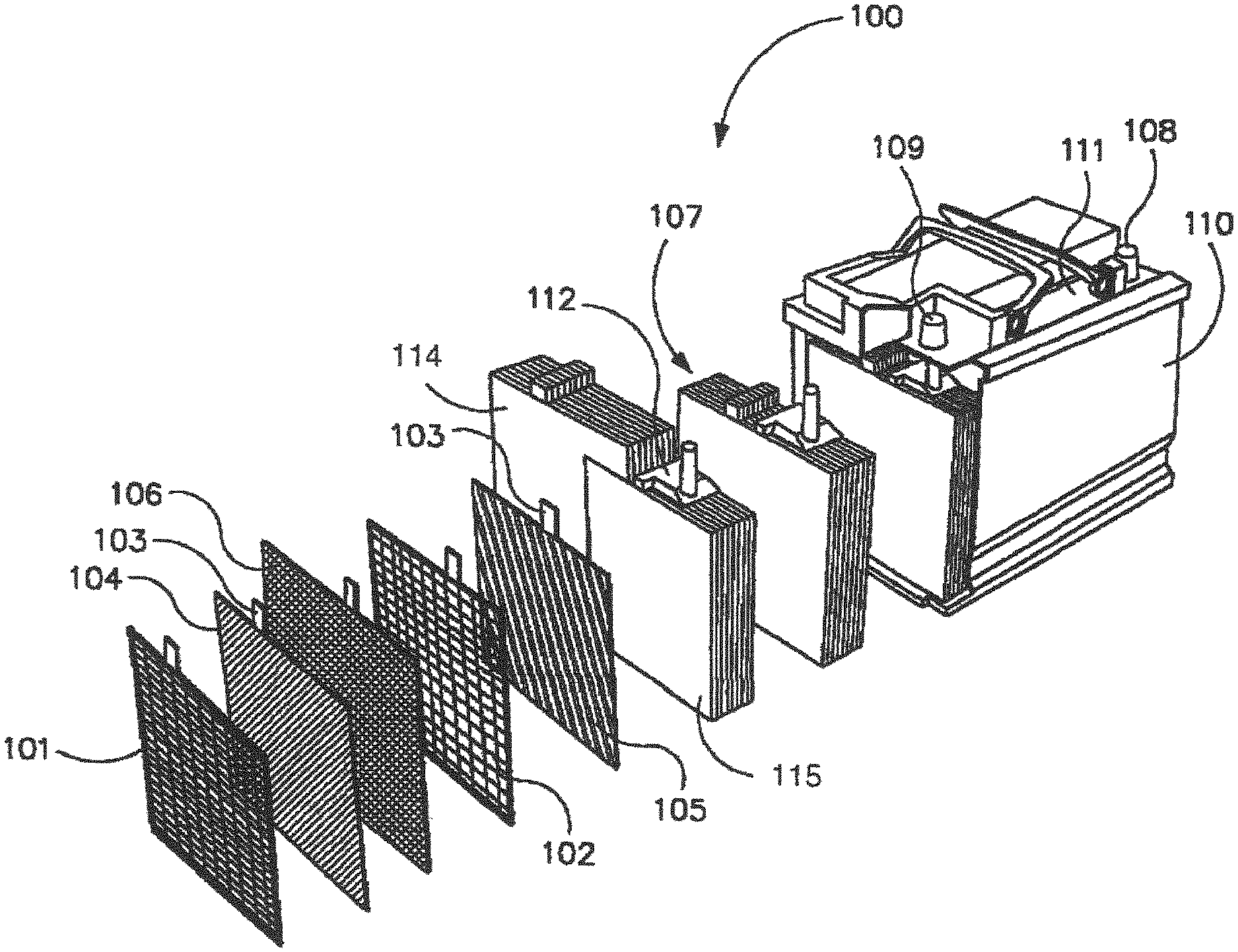
FIG. 1 illustrates an example basic design of an accumulator 100 according to the invention. The accumulator 100 can in particular be designed as a lead-acid battery having liquid electrolyte, for example in the form of sulfuric acid. The accumulator 100 has a housing 110 in which or more or more plate packs 107 are arranged. The accumulator 100 has a fixed number of plate packs 107 based on its number of cells. The plate packs 107 are respectively arranged in individual holding chambers of the housing 110 separated from one another by partitions. The plate packs 107 are connected together into a series connection within the housing 110 by internal connecting elements not depicted in FIG. 1. The positive plates at the one end of the plate pack and the negative plates at the other end of the plate pack are electrically connected to respective external terminals 108, 109 located in a cover part 111 of the accumulator housing 110. The electrical energy of the accumulator 100 is supplied to electrical loads through terminals 108, 109.
The plate packs 107 comprise respectively alternating positive and negative electrode plates. The negative electrode plates are depicted as negative plate group 115, the positive electrode plates as positive plate group 114. FIG. 1 includes a depiction of individual electrode plates for illustrative purposes; i.e. a negative electrode plate 105 comprising a negative flat lead grid 102 and a positive electrode plate 104 comprising a positive flat lead grid 101. The positive electrode plate 104 and the negative electrode plate 105 depicted in FIG. 1 already exhibit a pasting with active mass, same covering the individual grid bars and cutouts. The positive and/or negative lead grid comprise(s) a plurality of grid bars and a plurality of window-like cutouts formed between the grid bars. The positive and/or negative lead grid 101, 102 can be produced for example in a stamping process or by means of other methods such as casting and/or rolling.
The positive electrode plate 104 is additionally separated from the negative electrode plate 105 by a separator material 106. The separator material 106 can in particular be formed into the shape of a pouch to accommodate the positive electrode plate 104 and separate it from adjacent electrode plates.
The positive electrode plates 104 each comprise a respective connecting lug 103 by means of which the electrode plates in the positive plate group 114 are connected together into a parallel connection. The negative electrode plates 105 each comprise a respective connecting lug 103 by means of which the electrode plates in the negative plate group 115 are connected together into a parallel connection. The connection can be made by a connector 112 soldered or welded onto the connecting lugs 103 as is recognizable in FIG. 1.
The accumulator 100 according to FIG. 1 can in particular comprise one or more inventive electrode plates, e.g. in the form of positive electrode plates 104.
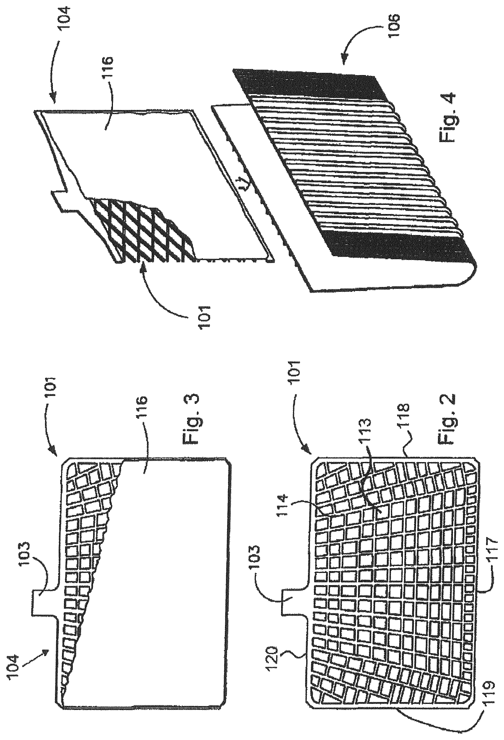
FIG. 2 shows an example of a positive lead grid 101 in a top plan view. It can be seen that the lead grid 101 has a plurality of grid bars 114, between which is a plurality of window-like cutouts 113. To make it easier to handle and for purposes of mechanical stability as well as improved electrical properties, the outer edge of the lead grid 101 can exhibit one, some or all of the following cited frame sections: upper frame section 115, left side frame section 119, lower frame section 117, right side frame section 118.
FIG. 3 shows the lead grid 101 from FIG. 2 after having been at least partly covered with active mass, which is usually applied in paste form. This process is also known as pasting. FIG. 4 shows the lead grid 103 of FIG. 3 having been provided with the active mass being inserted into a wrapper-like separator 106.
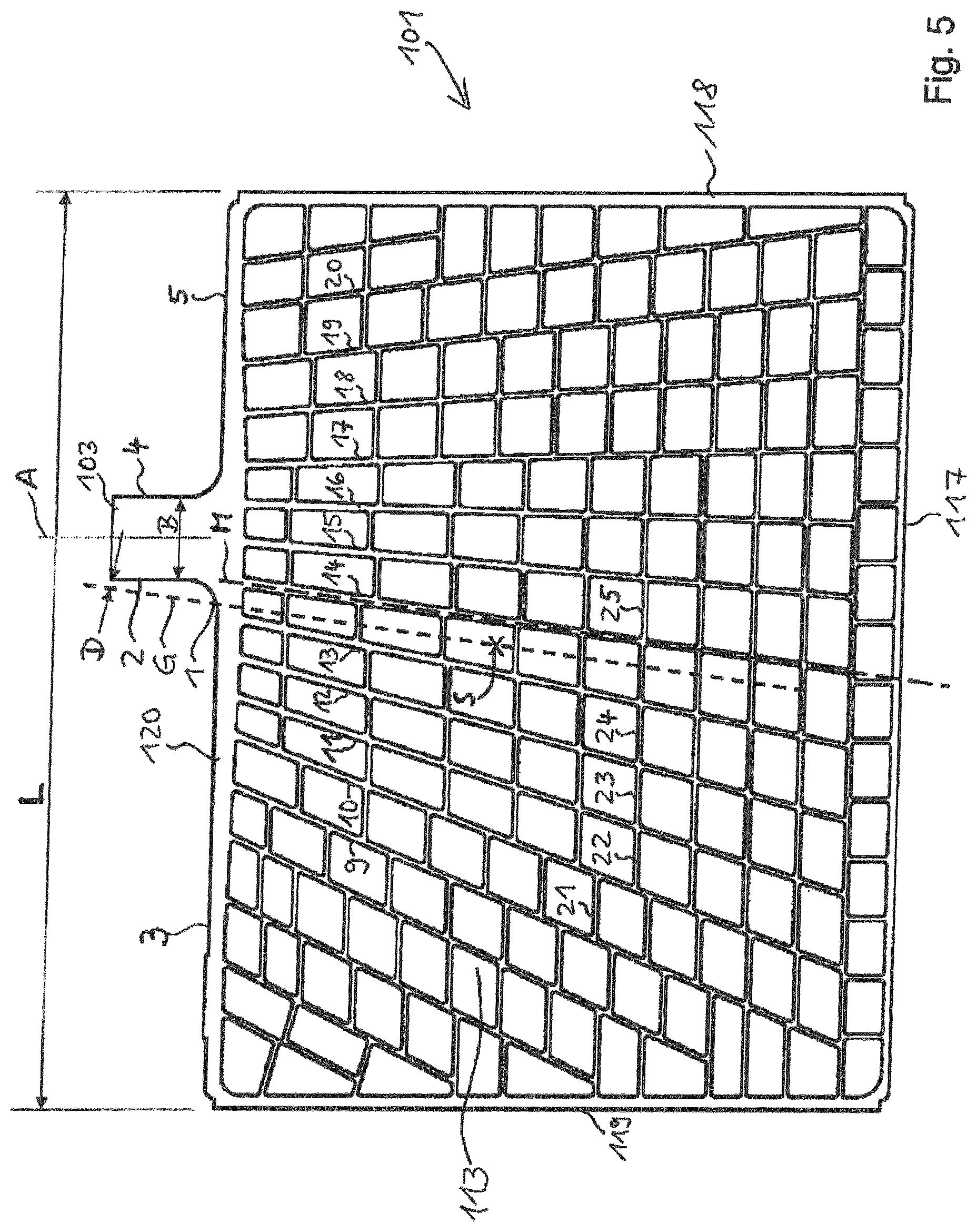
FIG. 5 shows a grid arrangement 101 formed according to the invention, again comprising a frame having an upper frame element 120, a lower frame element 117, a right side frame element 118 and a left side frame element 119. The grid 113 is situated within the area enclosed by the above-cited frame elements. As can be seen, the connecting lug 103 disposed on the upper frame element 120 is arranged asymmetrically on the upper frame element 120, somewhat to the right of the grid arrangement center. A vertical central axis A running exactly vertical intersects the center of the connecting lug 103. The vertical central axis A thereby also serves as a vertical reference axis.
Further reference numerals are provided in FIG. 5 to specify the grid 113 in greater detail. The grid 113 comprises a plurality of horizontal bars; of these, horizontal bars 21 to 25 have been provided with reference numerals for illustrative purposes. The horizontal bars extend substantially horizontally. Vertical bars intersect or cross or are tangent to the horizontal bars. Of the vertical bars, vertical bars 9 to 20 have been provided with reference numerals for illustrative purposes. The vertical bars do not run exactly vertically but rather at different angles to each other in the shape of a fan, whereby they radiate outwardly from the upper frame element 120. The vertical bars identified by reference numerals 9 to 20 intersect both the upper frame element as well as, at least in a mathematical extension, the lower frame element 117. Further vertical bars arranged to the left and right thereof, which are not provided with reference numerals, do not intersect the lower frame element 117, not even in a mathematical extension.
It is provided with the grid arrangement according to the invention for the sum of all the angles of the vertical bars 9 to 20; i.e. the vertical bars intersecting both the upper as well as the lower frame element of the grid arrangement, or at least intersecting in mathematical extension, to be greater than 7.degree.. The angles are defined here with respect to the vertical reference axis A. This results in the sum of all the angles being approximately equivalent to the intersecting angle of central axis M with vertical reference axis A. In other words, the angle of inclination to the vertical reference axis A yielded by the summation is a value greater than 7.degree..
In corresponding manner, the inventive grid arrangement also exhibits a value greater than 7.degree., again relative to the vertically extending reference axis A, with respect to the sum of the angles of the outermost left vertical bar 9 and the outermost right vertical bar 20 which intersect both the upper and well as the lower frame element of the grid arrangement, or at least would intersect in mathematical extension.
The connecting lug 103 has a first vertical side 2 arranged on the side of the longer leg 3 of the upper frame element 120. An opposite second vertical side 4 is arranged on the side of the shorter leg 5 of the upper frame element 120. The legs 3, 5 are formed to the respective left and right of the connecting lug 103.
The center of gravity S is plotted in the grid arrangement according to FIG. 5. Vertical bar 14 is the vertical bar situated closest the center of gravity S; i.e. the vertical bar having the least distance from the center of gravity S. The central axis M of vertical bar 14 is also plotted in FIG. 5. A parallel to central axis M running through the center of gravity S is further plotted as straight line G. Said straight line G passes the connecting lug 103 on the first vertical side 2 at a distance D. In the grid arrangement according to the invention, the straight line G can also intersect the connecting lug 103, particularly in the area of the first vertical side 2. The intersecting point can also be situated at other locations on the connecting lug 103, ranging to the second vertical side 4 of the connecting lug 103 opposite from the first vertical side 2.
It can further be provided in the inventive grid arrangement for a point 1 at which the straight line G intersects the upper frame element 120 to be situated at a distance less than 15%, in particular less than 10% of the length L of the upper frame element 120 from the vertical central axis A of the connecting lug 103. The length L of the upper frame element 120, which also concurrently corresponds to the width of the grid arrangement 101, is plotted in FIG. 5. The width B of the connecting lug 103 is likewise plotted.
FIG. 6 shows a further inventive grid arrangement 101 having a narrower structure than the embodiment according to FIG. 5. The length L of the upper frame element is thus shorter than in the embodiment according to FIG. 5. Because of the shorter total width, the grid arrangement 101 according to FIG. 6 has fewer vertical bars. Among the vertical bars, only vertical bars 9, 10, 11, 14, 17, 18, 19 and 20 intersect the upper frame element and, at least in mathematical extension, also the lower frame element 117. Of this subset of vertical bars, vertical bar 9 is again the outermost left vertical bar and vertical bar 20 the outermost right vertical bar. Further vertical bars not provided with reference numerals are arranged to the left and right of this subset of vertical bars and also do not intersect the lower frame element 117 in extension. In the embodiment according to FIG. 6, vertical bar 14 is again the vertical bar situated closest to the center of gravity S of the grid arrangement 101.
The reference numerals of FIG. 6 otherwise correspond to those of FIG. 5.
To aid in identification, FIG. 6 also separately plots, to the right of the grid arrangement, the arrangement of the center of gravity S, central axis M and straight line G as well as the distance D from the connecting lug 103 without the grid bars. The course of straight line G in the left part of FIG. 6 is somewhat hard to distinguish due to part of it running along the edge of vertical bar 14.
The embodiments according to FIGS. 5 and 6 document the universal applicability of the present invention.
As utilized herein, the terms "approximately," "about," "substantially", and similar terms are intended to have a broad meaning in harmony with the common and accepted usage by those of ordinary skill in the art to which the subject matter of this disclosure pertains. It should be understood by those of skill in the art who review this disclosure that these terms are intended to allow a description of certain features described and claimed without restricting the scope of these features to the precise numerical ranges provided. Accordingly, these terms should be interpreted as indicating that insubstantial or inconsequential modifications or alterations of the subject matter described and claimed are considered to be within the scope of the invention as recited in the appended claims.
It should be noted that references to relative positions (e.g., "top" and "bottom") in this description are merely used to identify various elements as are oriented in the Figures. It should be recognized that the orientation of particular components may vary greatly depending on the application in which they are used.
For the purpose of this disclosure, the term "coupled" means the joining of two members directly or indirectly to one another. Such joining may be stationary in nature or moveable in nature. Such joining may be achieved with the two members or the two members and any additional intermediate members being integrally formed as a single unitary body with one another or with the two members or the two members and any additional intermediate members being attached to one another. Such joining may be permanent in nature or may be removable or releasable in nature.
It is also important to note that the construction and arrangement of the system, methods, and devices as shown in the various examples of embodiments is illustrative only. Although only a few embodiments have been described in detail in this disclosure, those skilled in the art who review this disclosure will readily appreciate that many modifications are possible (e.g., variations in sizes, dimensions, structures, shapes and proportions of the various elements, values of parameters, mounting arrangements, use of materials, colors, orientations, etc.) without materially departing from the novel teachings and advantages of the subject matter recited. For example, elements shown as integrally formed may be constructed of multiple parts or elements show as multiple parts may be integrally formed, the operation of the interfaces may be reversed or otherwise varied, the length or width of the structures and/or members or connector or other elements of the system may be varied, the nature or number of adjustment positions provided between the elements may be varied (e.g. by variations in the number of engagement slots or size of the engagement slots or type of engagement). The order or sequence of any process or method steps may be varied or re-sequenced according to alternative embodiments. Other substitutions, modifications, changes and omissions may be made in the design, operating conditions and arrangement of the various examples of embodiments without departing from the spirit or scope of the present inventions.
While this invention has been described in conjunction with the examples of embodiments outlined above, various alternatives, modifications, variations, improvements and/or substantial equivalents, whether known or that are or may be presently foreseen, may become apparent to those having at least ordinary skill in the art. Accordingly, the examples of embodiments of the invention, as set forth above, are intended to be illustrative, not limiting. Various changes may be made without departing from the spirit or scope of the invention. Therefore, the invention is intended to embrace all known or earlier developed alternatives, modifications, variations, improvements and/or substantial equivalents.
The technical effects and technical problems in the specification are exemplary and are not limiting. It should be noted that the embodiments described in the specification may have other technical effects and can solve other technical problems.
* * * * *
References
D00000
D00001
D00002
D00003
D00004
XML
uspto.report is an independent third-party trademark research tool that is not affiliated, endorsed, or sponsored by the United States Patent and Trademark Office (USPTO) or any other governmental organization. The information provided by uspto.report is based on publicly available data at the time of writing and is intended for informational purposes only.
While we strive to provide accurate and up-to-date information, we do not guarantee the accuracy, completeness, reliability, or suitability of the information displayed on this site. The use of this site is at your own risk. Any reliance you place on such information is therefore strictly at your own risk.
All official trademark data, including owner information, should be verified by visiting the official USPTO website at www.uspto.gov. This site is not intended to replace professional legal advice and should not be used as a substitute for consulting with a legal professional who is knowledgeable about trademark law.