Optical system and image pickup apparatus
Katayose November 17, 2
U.S. patent number 10,838,201 [Application Number 16/158,413] was granted by the patent office on 2020-11-17 for optical system and image pickup apparatus. This patent grant is currently assigned to CANON KABUSHIKI KAISHA. The grantee listed for this patent is CANON KABUSHIKI KAISHA. Invention is credited to Masato Katayose.


| United States Patent | 10,838,201 |
| Katayose | November 17, 2020 |
Optical system and image pickup apparatus
Abstract
An optical system of this invention includes a first lens unit having a positive refractive power that is moved to an object side for focusing from infinity to a close distance. The first lens unit consists of, in order from the object side to an image side, a first lens sub-unit, an aperture stop, and a second lens sub-unit including a positive lens. A positive lens made of a material having an extraordinary dispersion characteristic .DELTA..theta.gF which is largest among the positive lenses included in the second lens sub-unit is represented by positive lens Lp. An extraordinary dispersion characteristic of the material of the positive lens Lp, a focal length of the positive lens Lp, a focal length of the first lens unit, a focal length of the first lens sub-unit, and a focal length f1b of the second lens sub-unit are each appropriately set.
| Inventors: | Katayose; Masato (Utsunomiya, JP) | ||||||||||
|---|---|---|---|---|---|---|---|---|---|---|---|
| Applicant: |
|
||||||||||
| Assignee: | CANON KABUSHIKI KAISHA (Tokyo,
JP) |
||||||||||
| Family ID: | 66096463 | ||||||||||
| Appl. No.: | 16/158,413 | ||||||||||
| Filed: | October 12, 2018 |
Prior Publication Data
| Document Identifier | Publication Date | |
|---|---|---|
| US 20190113721 A1 | Apr 18, 2019 | |
Foreign Application Priority Data
| Oct 16, 2017 [JP] | 2017-200166 | |||
| Current U.S. Class: | 1/1 |
| Current CPC Class: | G02B 27/0062 (20130101); G02B 9/06 (20130101) |
| Current International Class: | G02B 27/00 (20060101); G02B 15/177 (20060101); G02B 15/20 (20060101) |
References Cited [Referenced By]
U.S. Patent Documents
| 2018/0372993 | December 2018 | Katayose |
| 2013178365 | Sep 2013 | JP | |||
| 2013218015 | Oct 2013 | JP | |||
| 2015200845 | Nov 2015 | JP | |||
| 2016061903 | Apr 2016 | JP | |||
| 2016061919 | Apr 2016 | JP | |||
Other References
|
Tomohiko, "Optical System and Imaging Apparatus Using the Same", JP 2013218015, machine translation (Year: 2013). cited by examiner . Notice of Reasons for Refusal issued by the Japan Patent Office on Jun. 2, 2020 in corresponding JP Patent Application No. 2017-200166, with English translation. cited by applicant. |
Primary Examiner: Huang; Wen
Attorney, Agent or Firm: Carter, DeLuca & Farrell LLP
Claims
What is claimed is:
1. An optical system comprising a first lens unit having a positive refractive power that is configured to move to an object side for focusing from infinity to a close distance, wherein: the first lens unit consists of, in order from the object side to an image side, a first lens sub-unit, an aperture stop, and a second lens sub-unit comprising one or more positive lenses; and the following conditional expressions are satisfied: 0.0<.DELTA..theta.gFLp, 0.4<fLp/f1<1.2, 0.15<f1b/f1a<0.60, 0.0 1<bf/f1b<0.60, and 0.01<bf/f1b<0.40 where .DELTA..theta.gFLp is an extraordinary dispersion characteristic of the material of a positive lens Lp, the positive lens LP being included in the one or more positive lenses included in the second lens sub-unit, the positive lens LP being made of a material having a largest extraordinary dispersion characteristic among extraordinary dispersion characteristics of materials of the one or more positive lenses included in the second lens sub-unit, fLp is a focal length of the positive lens Lp, f1 is a focal length of the first lens unit, f1 a is a focal length of the first lens sub-unit, f1b is a focal length of the second lens sub-unit, and bf is a back focus when focusing at infinity.
2. The optical system according to claim 1, wherein, the following conditional expression is satisfied: 50.0<.nu.dLp where .nu.dLp is an Abbe number at a d-line of the material of the positive lens Lp.
3. The optical system according to claim 1, wherein: the second lens sub-unit comprises one or more positive lenses on the image side of the positive lens Lp, and the following conditional expression is satisfied: 0.2<fLpr/fLp<1.1 where fLpr is a focal length of a positive lens Lpr having a strongest refractive power among the one or more positive lenses on the image side of the positive lens Lp.
4. The optical system according to claim 1, wherein: the second lens sub-unit comprises a cemented lens Lpc formed by cementing together the positive lens Lp and a negative lens, and a cemented lens Lc2 formed by cementing together a plurality of lenses that is disposed on the image side of the cemented lens Lpc, and, the following conditional expression is satisfied: -0.80<fLpc/fLc2<-0.15 where fLpc is a focal length of the cemented lens Lpc and fLc2 is a focal length of the cemented lens Lc2.
5. The optical system according to claim 1, wherein: the following conditional expression is satisfied: 1.60<Ndrave<1.83 where Ndrave is an average value of refractive indexes at a d-line of the materials of the one or more positive lenses included in the second lens sub-unit.
6. The optical system according to claim 1, wherein: the second lens sub-unit comprises one or more positive lenses on the image side of the positive lens Lp, and the following conditional expression is satisfied: 0<.theta.gFpa-(-1.720.times.10.sup.-7.times..nu.dpa.sup.3+5.572.times.- 10.sup.-5.times..nu.dpa.sup.2-5.755.times.10.sup.-3.times..nu.dpa+0.7245) where .nu.dpa and .theta.gFpa are respectively an Abbe number and a partial dispersion ratio of a material of a positive lens Lpa that is one positive lens among the one or more positive lenses on the image side of the positive lens Lp.
7. The optical system according to claim 6, wherein: the following conditional expression is satisfied: 0.20<fLpa/f1<1.00 where fLpa is a focal length of the positive lens Lpa.
8. The optical system according to claim 1, wherein: the second lens sub-unit comprises one or more negative lenses, and the following conditional expression is satisfied: .theta.gFna-(-4.516.times.10.sup.-5.times..nu.dna.sup.2+1.291.times.10.su- p.-3.times..nu.dna+0.965)<0.0 where .nu.dna and .theta.gFna are respectively an Abbe number and a partial dispersion ratio of a material of one negative lens Lna among the one or more negative lenses.
9. The optical system according to claim 1, comprising: a second lens unit having a positive refractive power that is disposed adjacent to an image side of the first lens unit, wherein the second lens unit is immobile for focusing.
10. The optical system according to claim 1, comprising: a second lens unit having a positive refractive power that is disposed adjacent to an image side of the first lens unit, wherein the second lens unit is moved to the image side for focusing from infinity to a close distance.
11. An image pickup apparatus comprising: the optical system according to claim 1, and an image pickup element that receives light of an image that is formed by the optical system.
12. An optical system consisting of a first lens unit having a positive refractive power that is configured to move to an object side for focusing from infinity to a close distance, wherein: the first lens unit consists of a first lens sub-unit, an aperture stop, and a second lens sub-unit comprising one or more positive lenses, which are arranged in that order from the object side to an image side; and the following conditions are satisfied: 0.0<.theta.gFLp, 0.4<fLp/f1<1.2, and 0.15<f1b/f1a<0.60 where .DELTA..theta.gFLp is an extraordinary dispersion characteristic of the material of a positive lens Lp, the positive lens LP being included in the one or more positive lenses included in the second lens sub-unit, the positive lens LP being made of a material having a largest extraordinary dispersion characteristic among extraordinary dispersion characteristics of materials of the one or more positive lenses included in the second lens sub-unit, fLp is a focal length of the positive lens Lp, f1 is a focal length of the first lens unit, f1a is a focal length of the first lens sub-unit, and f1b is a focal length of the second lens sub-unit.
13. An image pickup apparatus comprising: the optical system according to claim 12, and an image pickup element that receives light of an image that is formed by the optical system.
14. An optical system consisting of a first lens unit having a positive refractive power that is configured to move to an object side for focusing from infinity to a close distance, and a second lens unit that is moved for focusing from infinity to a close distance, wherein: the first lens unit consists of a first lens sub-unit, an aperture stop, and a second lens sub-unit comprising one or more positive lenses, which are arranged in that order from the object side to an image side; and: the following conditions are satisfied: 0.0<.DELTA..theta.gFLp, 0.4<fLp/f1<1.2, and 0.15<f1b/f1a<0.60 where a positive lens .DELTA..theta.gFLp is an extraordinary dispersion characteristic of the material of the positive lens Lp, the positive lens LP being included in the one or more positive lenses included in the second lens sub-unit, the positive lens LP being made of a material having a largest extraordinary dispersion characteristic among extraordinary dispersion characteristics of materials of the one or more positive lenses included in the second lens sub-unit, fLp is a focal length of the positive lens Lp, f1 is a focal length of the first lens unit, f1a is a focal length of the first lens sub-unit, and f1b is a focal length of the second lens sub-unit.
15. An image pickup apparatus comprising: the optical system according to claim 14, and an image pickup element that receives light of an image that is formed by the optical system.
Description
BACKGROUND OF THE INVENTION
Field of the Invention
The present invention relates to an optical system, and more particularly is suitable as an image pickup optical system of an image pickup apparatus such as a single-lens reflex camera, a digital still camera, a TV camera, a video camera or a monitoring camera.
Description of the Related Art
For image pickup optical systems that are used in image pickup apparatuses which use an image pickup element, in addition to a demand to enhance image quality (achieve a high resolution), there is also a demand for a bokeh effect in an image to be favorable. An image pickup optical system having a high aperture ratio is known as an image pickup optical system that satisfies these demands. For image pickup optical systems having a higher aperture ratio, since the depth of field is shallow, there is a desire to favorably correct aberrations including chromatic aberration in order to make a bokeh effect look beautiful while enhancing the image quality.
Various image pickup optical systems that have a high aperture ratio which are configured to favorably correct aberrations including chromatic aberration have already been proposed (Japanese Patent Application Laid-Open No. 2013-218015 and Japanese Patent Application Laid-Open No. 2015-200845).
Japanese Patent Application Laid-Open No. 2013-218015 discloses an optical system consisting of a first lens unit having a positive refractive power and a second lens unit having a positive or negative refractive power which are arranged in that order from an object side to an image side, in which the first lens unit is moved for focusing.
Japanese Patent Application Laid-Open No. 2015-200845 discloses an optical system consisting of a front unit having a positive or negative refractive power, an aperture stop, and a rear unit having a positive refractive power which are arranged in that order from an object side to an image side. In Japanese Patent Application Laid-Open No. 2015-200845, the front unit consists of a first lens unit having a positive or negative refractive power and a second lens unit having a positive refractive power, and the rear unit consists of a third lens unit having a positive refractive power. The second lens unit and the third lens unit are moved for focusing.
In an optical system having a high aperture ratio, because the depth of field becomes shallow, the influence that aberrations such as axial chromatic aberration, chromatic aberration of magnification, spherical aberration, comatic aberration or astigmatism have on image quality increases. In an optical system having a high aperture ratio, in order to favorably correct aberrations such as spherical aberration, comatic aberration and astigmatism while reducing the overall size, it is effective to use a material having a high refractive index and comparatively low dispersion for a positive lens included in a first lens unit having a positive refractive power.
However, in a material having a high refractive index and low dispersion, an extraordinary dispersion characteristic is generally low. Therefore, correction of the secondary spectrum of axial chromatic aberration is difficult, and correcting axial chromatic aberration in a well-balanced manner becomes difficult. In particular, if axial chromatic aberration that arises in a focusing unit that is moved for focusing is not adequately corrected, variations in axial chromatic aberration caused by focusing increase and it is difficult to achieve enhanced image quality over the entire object distance from infinity to a close distance.
To achieve enhanced image quality over the entire object distance from infinity to a close distance it is necessary to correct aberrations such as axial chromatic aberration, chromatic aberration of magnification, spherical aberration, comatic aberration and astigmatism in a well-balanced manner. In order to do so, it is important to appropriately set the refractive power and the like of each lens unit and the material of lenses included in a focusing unit.
SUMMARY OF THE INVENTION
The optical system of the present invention is an optical system including a first lens unit having a positive refractive power that is moved to an object side for focusing from infinity to a close distance, wherein:
the first lens unit consists of, in order from the object side to an image side, a first lens sub-unit, an aperture stop, and a second lens sub-unit including one or more positive lenses; and
the following conditional expressions are satisfied: 0.0<.DELTA..theta.gFLp, 0.4<fLp/f1<1.2, and 0.15<f1b/f1a<0.60 where .DELTA..theta.gFLp is an extraordinary dispersion characteristic of the material of a positive lens Lp, the positive lens LP being included in the one or more positive lenses included in the second lens sub-unit, the positive lens LP being made of a material having the largest extraordinary dispersion characteristic among extraordinary dispersion characteristics of materials of the one or more positive lenses included in the second lens sub-unit, fLp is a focal length of the positive lens Lp, f1 is a focal length of the first lens unit, f1a is a focal length of the first lens sub-unit, f1b is a focal length of the second lens sub-unit, and bf is a back focus when focusing at infinity.
Further features of the present invention will become apparent from the following description of exemplary embodiments with reference to the attached drawings.
BRIEF DESCRIPTION OF THE DRAWINGS
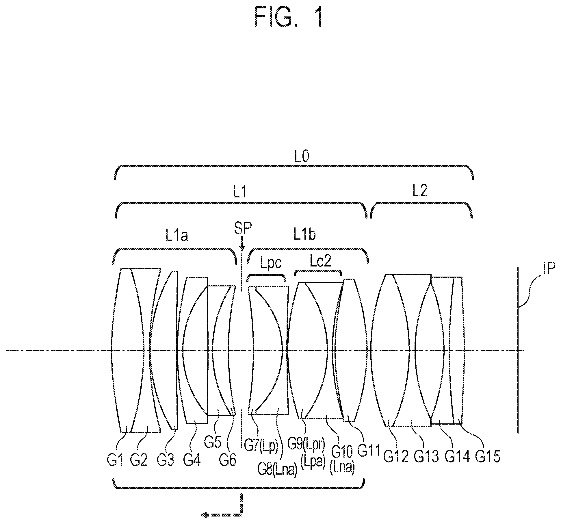
FIG. 1 is a cross-sectional view of lenses of an optical system of Embodiment 1.
FIG. 2A is an aberration graph when focused at infinity of the optical system of Embodiment 1.
FIG. 2B is an aberration graph when focused at the minimum object distance of the optical system of Embodiment 1.
FIG. 3 is a cross-sectional view of lenses of an optical system of Embodiment 2.
FIG. 4A is an aberration graph when focused at infinity of the optical system of Embodiment 2.
FIG. 4B is an aberration graph when focused at the minimum object distance of the optical system of Embodiment 2.
FIG. 5 is a cross-sectional view of lenses of an optical system of Embodiment 3.
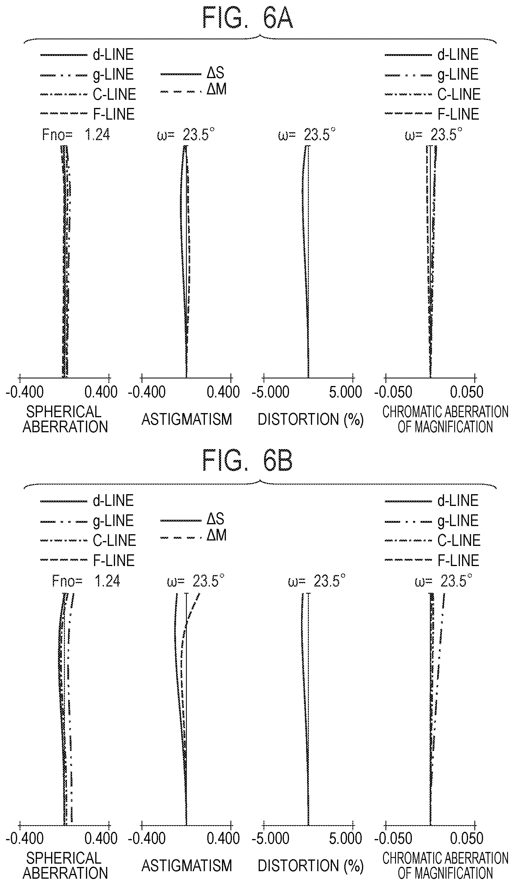
FIG. 6A is an aberration graph when focused at infinity of the optical system of Embodiment 3.
FIG. 6B is an aberration graph when focused at the minimum object distance of the optical system of Embodiment 3.
FIG. 7 is a cross-sectional view of lenses of an optical system of Embodiment 4.
FIG. 8A is an aberration graph when focused at infinity of the optical system of Embodiment 4.
FIG. 8B is an aberration graph when focused at the minimum object distance of the optical system of Embodiment 4.
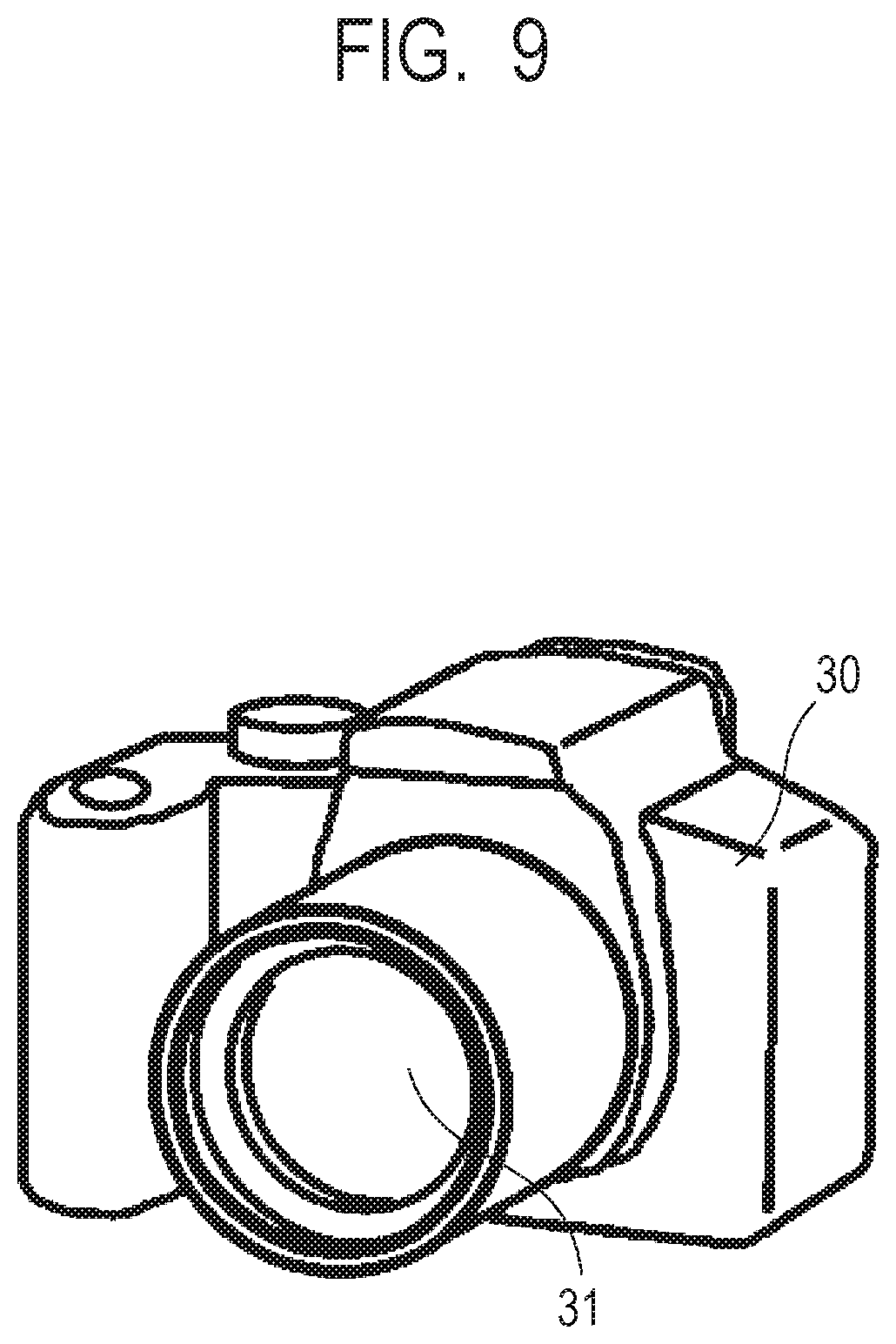
FIG. 9 is a schematic view of main portions of an image pickup apparatus of the present invention.
DESCRIPTION OF THE EMBODIMENTS
Preferred embodiments of the present invention will now be described in detail in accordance with the accompanying drawings.
Hereunder, exemplary embodiments of the optical system and the image pickup apparatus will be described using the accompanying drawings.
The optical system of the exemplary embodiments includes a first lens unit having a positive refractive power that is moved to the object side for focusing from infinity to a close distance. The first lens unit consists of a first lens sub-unit, an aperture stop, and a second lens sub-unit including one or more positive lenses, that are arranged in that order from the object side to the image side.
FIG. 1 is a cross-sectional view of lenses of an optical system of Embodiment 1. FIGS. 2A and 2B are aberration graphs at a time when the optical system of Embodiment 1 is focused at infinity and focused at the minimum object distance, respectively. In the optical system of Embodiment 1, the F-number is 1.24 and the image pickup angle of view is 45.58 degrees.
FIG. 3 is a cross-sectional view of lenses of an optical system of Embodiment 2. FIGS. 4A and 4B are aberration graphs at a time when the optical system of Embodiment 2 is focused at infinity and focused at the minimum object distance, respectively. In the optical system of Embodiment 2, the F-number is 1.25 and the image pickup angle of view is 45.9 degrees.
FIG. 5 is a cross-sectional view of lenses of an optical system of Embodiment 3. FIGS. 6A and 6B are aberration graphs at a time when the optical system of Embodiment 3 is focused at infinity and focused at the minimum object distance, respectively. In the optical system of Embodiment 3, the F-number is 1.24 and the image pickup angle of view is 47.08 degrees.
FIG. 7 is a cross-sectional view of lenses of an optical system of Embodiment 4. FIGS. 8A and 8B are aberration graphs at a time when the optical system of Embodiment 4 is focused at infinity and focused at the minimum object distance, respectively. In the optical system of Embodiment 4, the F-number is 1.24 and the image pickup angle of view is 45.9 degrees.
FIG. 9 is a schematic view of main portions of an image pickup apparatus.
The optical system of each embodiment is an image pickup optical system that is used in an image pickup apparatus such as a video camera, a digital camera, a TV camera or a monitoring camera. In each cross-sectional view of lenses, the left side is the subject side (object side) (front), and the right side is the image side (rear). In each cross-sectional view of lenses, reference character L0 denotes an optical system. i represents the order of the relevant lens unit from the object side, and L1 represents an i-th lens unit.
In the cross-sectional view of lenses of Embodiments 1 to 3, reference character L1 denotes a first lens unit that has a positive refractive power, and reference character L2 denotes a second lens unit that has a positive refractive power. The first lens unit L1 consists of a first lens sub-unit L1a having a positive refractive power, an aperture stop SP, and a second lens sub-unit L1b having a positive refractive power, which are arranged in that order from the object side to the image side. The optical system L0 of Embodiments 1 to 3 is an optical system consisting of two lens units.
In the cross-sectional view of lenses of Embodiment 4, reference character L1 denotes a first lens unit that has a positive refractive power. The first lens unit L1 consists of a first lens sub-unit L1a having a positive refractive power, an aperture stop SP, and a second lens sub-unit L1b having a positive refractive power that are arranged in that order from the object side to the image side. Embodiment 4 is an optical system consisting of one lens unit.
In each cross-sectional view of lenses, reference character IP denotes an image plane, which is the position at which an image pickup surface of an image pickup element (photoelectrical conversion element) such as a CCD sensor or a CMOS sensor is placed when the optical system is used as an image pickup optical system of a video camera or a digital still camera.
In the aberration graphs, reference characters d, g, C and F denote a d-line (wavelength of 587.6 nm), a g-line (wavelength of 435.8 nm), a C-line (wavelength of 656.3 nm) and an F-line (wavelength of 486.1 nm), respectively. The symbols .DELTA.M and .DELTA.S denote the meridional image plane of the d-line and the sagittal image plane of the d-line, respectively. Further, distortion is represented by the d-line. Furthermore, .omega. represents the half angle of view (value of one-half of the image pickup angle of view) (degrees), and Fno represents the F-number.
Embodiments 1 to 3 include the second lens unit L2 that has a positive refractive power which is disposed adjacent to the image side of the first lens unit L1. In Embodiments 1 and 2, for focusing from infinity to a close distance, the first lens unit L1 is moved to the object side as indicated by a broken-line arrow. The second lens unit L2 is immobile.
In Embodiment 3, focusing is performed by independently moving each of the first lens unit L1 and the second lens unit L2 in the optical axis direction. For focusing from infinity to a close distance, the first lens unit L1 is moved to the object side as indicated by the broken-line arrow, and the second lens unit L2 is moved to the image side. In Embodiment 4, for focusing from infinity to a close distance, the first lens unit L1 is moved to the object side as indicated by the broken-line arrow.
Each embodiment includes the first lens unit L1 having a positive refractive power that is moved to the object side for focusing from infinity to a close distance. The first lens unit consists of a first lens sub-unit L1a, an aperture stop SP, and a second lens sub-unit L1b having one or more positive lenses, which are arranged in that order from the object side to the image side.
Here, a positive lens that is made of a material having an extraordinary dispersion characteristic .DELTA..theta.gF that is largest among the positive lenses included in the second lens sub-unit L1b will be represented by positive lens Lp, an extraordinary dispersion characteristic of the material of the positive lens Lp will be represented by .DELTA..theta.gFLp, and the focal length of the positive lens Lp will be represented by fLp. Further, the focal length of the first lens unit L1 will be represented by f1, the focal length of the first lens sub-unit L1a will be represented by f1a, and the focal length of the second lens sub-unit L1b will be represented by f1b.
In this case, the following conditional expressions are satisfied: 0.0<.DELTA..theta.gFLp (1) 0.4<fLp/f1<1.2 (2) 0.15<f1b/f1a<0.60 (3).
In this case, when the refractive indexes of the material with respect to the g-line (wavelength of 435.8 nm), F-line (486.1 nm), C-line (656.3 nm) and d-line (587.6 nm) are represented by Ng, NF, NC and Nd, respectively, the Abbe number .nu.d and the partial dispersion ratio .theta.gF of the material are represented by the following equations. .nu.d=(Nd-1)/(NF-NC) .theta.gF=(Ng-NF)/(NF-NC)
Further, the extraordinary dispersion characteristic .DELTA..theta.gF is defined by the following conditional expression. .DELTA..theta.gF=.theta.gF+0.001618.times..nu.d-0.6415
Next, the technical meaning of each of the foregoing conditional expressions will be described.
The conditional expression (1) appropriately defines an extraordinary dispersion characteristic of the positive lens Lp included in the second lens sub-unit L1b in order to satisfactorily correct axial chromatic aberration and chromatic aberration of magnification that arise in the first lens unit L1 that has a positive refractive power.
In order to satisfactorily correct axial chromatic aberration, it is necessary to make the secondary spectrum of the axial chromatic aberration as small as possible. In each of the exemplary embodiments, in order to correct the secondary spectrum of axial chromatic aberration of the first lens unit L1 that has a positive refractive power, a material having a high extraordinary dispersion characteristic is used for the positive lens Lp. Further, the secondary spectrum of chromatic aberration of magnification is also satisfactorily corrected by disposing the positive lens Lp which is made using a material having a high extraordinary dispersion characteristic on the image side relative to the aperture stop SP.
By using a material having an extraordinary dispersion characteristic that is greater than the lower limit value of the conditional expression (1) in the positive lens Lp included in the second lens sub-unit L1b, the secondary spectra of axial chromatic aberration and chromatic aberration of magnification are satisfactorily corrected.
The conditional expression (2) appropriately defines a ratio between the focal length of the positive lens Lp and the focal length of the first lens unit L1 having a positive refractive power in order to satisfactorily correct aberrations that include chromatic aberration that arise in the first lens unit L1 that has a positive refractive power. If the focal length of the positive lens Lp is long to an extent such that the focal length exceeds the upper limit of the conditional expression (2), because the effect of correcting the secondary spectra of axial chromatic aberration and chromatic aberration of magnification decreases, it becomes difficult to satisfactorily correct axial chromatic aberration and chromatic aberration of magnification.
If the focal length of the positive lens Lp is short to an extent such that the focal length is less than the lower limit of the conditional expression (2), because the curvature radius of each lens surface of the positive lens Lp will be too small, the occurrence of aberrations such as spherical aberration, comatic aberration and astigmatism will decrease, and correction of aberrations will be difficult.
The conditional expression (3) appropriately defines a ratio between the focal length of the first lens sub-unit L1a and the focal length of the second lens sub-unit L1b in order to satisfactorily correct aberrations that include chromatic aberration that arise in the first lens unit L1 that has a positive refractive power.
In each exemplary embodiment, in a case where a material having a high extraordinary dispersion characteristic is used in a positive lens in the first lens sub-unit L1a having a positive refractive power that is disposed on the object side relative to the aperture stop SP, although correction of the secondary spectrum of axial chromatic aberration will be easy, correction of the secondary spectrum of chromatic aberration of magnification will be difficult. However, in a case where a material having a high extraordinary dispersion characteristic is used in a positive lens in the second lens sub-unit L1b having a positive refractive power that is disposed on the image side relative to the aperture stop SP, secondary spectrum correction with respect to both axial chromatic aberration and chromatic aberration of magnification is easy.
Therefore, by using a material having a high extraordinary dispersion characteristic in a positive lens that is included in the second lens sub-unit L1b, and setting the refractive power of the second lens sub-unit L1b to be stronger than the refractive power of the first lens sub-unit L1a, axial chromatic aberration and chromatic aberration of magnification are satisfactorily corrected.
If the focal length of the second lens sub-unit L1b is longer than the focal length of the first lens sub-unit L1a and exceeds the upper limit of the conditional expression (3), it will be difficult to satisfactorily correct both axial chromatic aberration and chromatic aberration of magnification. If the focal length of the second lens sub-unit L1b is shorter than the focal length of the first lens sub-unit L1a and is less than the lower limit of the conditional expression (3), it will be difficult to correct aberrations such as spherical aberration, comatic aberration and astigmatism.
Note that the numerical ranges of the conditional expressions (1), (2) and (3) can be more preferably set as follows. 0.005<.DELTA..theta.gFLp (1a) 0.5<fLp/f1<1.1 (2a) 0.18<f1b/f1a<0.55 (3a)
More preferably, the numerical ranges of the conditional expressions (1a), (2a) and (3a) can be set as follows. 0.010<.DELTA..theta.gFLp (1b) 0.6<fLp/f1<1.0 (2b) 0.22<f1b/f1a<0.50 (3b)
By adopting the above configuration, an optical system is obtained that, while having a high aperture ratio, satisfactorily corrects aberrations that include chromatic aberration and has high optical performance over the entire object distance from infinity to a close distance.
More preferably, in the respective exemplary embodiments, one or more of the following conditional expressions is satisfied.
Here, an Abbe number at a d-line of the material of the positive lens Lp will be represented by .nu.dLp. The second lens sub-unit L1b has one or more positive lenses on the image side of the positive lens Lp, and the focal length of the positive lens Lpr with the strongest refractive power among the one or more positive lenses will be represented by fLpr. The second lens sub-unit L1b has a cemented lens Lpc formed by cementing together a positive lens Lp and a negative lens, and a cemented lens Lc2 formed by cementing together a plurality of lenses that is disposed on the image side of the cemented lens Lpc, with the focal length of the cemented lens Lpc being represented by fLpc and the focal length of the cemented lens Lc2 being represented by fLc2.
Here, an average value of the refractive index at a d-line of the material of the positive lenses included in the second lens sub-unit L1b will be represented by Ndrave. The second lens sub-unit L1b has one or more positive lenses on the image side of the positive lens Lp, and one positive lens among the one or more positive lenses will be represented here by positive lens Lpa, with the Abbe number and the relative partial dispersion of the material of the positive lens Lpa being represented by .nu.dpa and .theta.gFpa, respectively. When the focal length of the positive lens Lpa is represented by fLpa, the second lens sub-unit L1b has one or more negative lenses, and the Abbe number and the relative partial dispersion of the material of one negative lens Lna among the one or more negative lenses are represented by .nu.dna and .theta.gFna, respectively. The back focus when focusing at infinity is represented by bf.
At such time, it is favorable to satisfy one or more of the following conditional expressions: 50.0<.nu.dLp (4) 0.2<fLpr/fLp<1.1 (5) -0.80<fLpc/fLc2<-0.15 (6) 1.60<Ndrave<1.83 (7) 0.0<.theta.gFpa-(-1.720.times.10.sup.-7.times..nu.dpa.sup.3+5.572.time- s.10.sup.-5.times..nu.dpa.sup.2-5.755.times.10.sup.-3.times..nu.dpa+0.7245- ) (8) 0.20<fLpa/f1<1.00 (9) .theta.gFna-(-4.516.times.10.sup.-5.times..nu.dna.sup.2+1.291.times.10.su- p.-3.times..nu.dna+0.965)<0.0 (10) 0.01<bf/f1b<0.60 (11).
Next, the technical meaning of each of the foregoing conditional expressions will be described. The conditional expression (4) appropriately defines an Abbe number at a d-line of the material of the positive lens Lp in order to satisfactorily correct axial chromatic aberration and chromatic aberration of magnification that arise in the first lens unit L1 that has a positive refractive power. By using a material having an Abbe number that is greater than the lower limit value of the conditional expression (4), it is easy to satisfactorily correct axial chromatic aberration and chromatic aberration of magnification.
The conditional expression (5) appropriately defines a ratio between the focal length of the positive lens Lp and the focal length of the positive lens Lpr in order to satisfactorily correct aberrations that include chromatic aberration that arise in the first lens unit L1 having a positive refractive power. If the focal length of the positive lens Lpr is long to an extent such that the focal length exceeds the upper limit of the conditional expression (5), or if the focal length of the positive lens Lp is short, the occurrence of aberrations such as spherical aberration, comatic aberration and astigmatism increases and correction of these aberrations becomes difficult. If the focal length of the positive lens Lpr is short to an extent such that the focal length is less than the lower limit of the conditional expression (5) or if the focal length of the positive lens Lp is long, it becomes difficult to correct axial chromatic aberration and chromatic aberration of magnification.
The conditional expression (6) appropriately defines a ratio between the negative focal length of the cemented lens Lpc and the positive focal length of the cemented lens Lc2 in order to satisfactorily correct aberrations that include chromatic aberration that arise in the first lens unit L1 that has a positive refractive power.
If the absolute value of the negative focal length of the cemented lens Lpc exceeds the upper limit of the conditional expression (6) and becomes small relative to the absolute value of the positive focal length of the cemented lens Lc2, correction of axial chromatic aberration and chromatic aberration of magnification will be difficult. If the absolute value of the negative focal length of the cemented lens Lpc is lower than the lower limit of the conditional expression (6) and becomes large relative to the absolute value of the positive focal length of the cemented lens Lc2, the occurrence of aberrations such as spherical aberration, comatic aberration and astigmatism increases, and correction of these aberrations becomes difficult.
The conditional expression (7) appropriately defines the average of the refractive indexes at a d-line of the materials of all of the positive lenses included in the second lens sub-unit L1b in order to satisfactorily correct aberrations that include chromatic aberration that arise in the first lens unit L1 that has a positive refractive power.
If the average value of the refractive indexes at the d-line of the materials of all of the positive lenses included in the second lens sub-unit L1b is large to an extent such that the average value exceeds the upper limit of the conditional expression (7), it means that a large amount of highly dispersive material is used, and correction of axial chromatic aberration and chromatic aberration of magnification will be difficult. If the average value of the refractive indexes at the d-line of the materials of the positive lenses in the second lens sub-unit L1b is small to an extent such that the average value is lower than the lower limit of the conditional expression (7), the curvature radius of the lens surfaces of the respective positive lenses decreases. Therefore, a large amount of aberrations such as spherical aberration, comatic aberration and astigmatism will arise, and correction of these aberrations will be difficult.
The conditional expression (8) appropriately defines the partial dispersion ratio of the material of the positive lens Lpa which is included in the second lens sub-unit L1b and which is disposed on the image side of the positive lens Lp, in order to satisfactorily correct axial chromatic aberration and chromatic aberration of magnification that arise inside the first lens unit L1 having a positive refractive power. By using a material having a partial dispersion ratio satisfying the conditional expression (8) in the positive lens Lpa, the secondary spectra of axial chromatic aberration and chromatic aberration of magnification are satisfactorily corrected. In particular, the secondary spectrum of chromatic aberration of magnification is satisfactorily corrected by arranging the positive lens Lpa on the image side of the positive lens Lp.
The conditional expression (9) appropriately defines the focal length of the positive lens Lpa in order to satisfactorily correct aberrations that include chromatic aberration that arise in the first lens unit L1 having a positive refractive power. If the focal length of the positive lens Lpa is long to an extent such that that the focal length exceeds the upper limit of the conditional expression (9), the effect of correcting the secondary spectra of axial chromatic aberration and chromatic aberration of magnification will decrease, and consequently it will be difficult to correct axial chromatic aberration and chromatic aberration of magnification. If the focal length of the positive lens Lpa is short to an extent such that that the focal length is less than the lower limit of the conditional expression (9), the curvature radius of the lens surface of the positive lens Lpa will be too small, and consequently a large amount of aberrations such as spherical aberration, comatic aberration and astigmatism will arise and it will be difficult to correct these aberrations.
The conditional expression (10) appropriately defines the partial dispersion ratio of the material of the negative lens Lna included in the second lens sub-unit L1b in order to satisfactorily correct axial chromatic aberration and chromatic aberration of magnification that arise in the first lens unit L1 having a positive refractive power.
In each exemplary embodiment, the secondary spectra of axial chromatic aberration and chromatic aberration of magnification are satisfactorily corrected by using a material having a high extraordinary dispersion characteristic as the material of the positive lens Lpa included in the second lens sub-unit L1b and using a material having a low extraordinary dispersion characteristic in the negative lens Lna.
By using a material having a partial dispersion ratio that satisfies the conditional expression (10) in the negative lens Lna included in the second lens sub-unit L1b, the secondary spectrum of axial chromatic aberration and chromatic aberration of magnification are satisfactorily corrected.
The conditional expression (11) appropriately defines a ratio between the back focus and the focal length of the second lens sub-unit L1b in order to achieve a reduction in the overall size of the optical system while satisfactorily correcting chromatic aberration that arises in the first lens unit L1 that has a positive refractive power.
If the back focus is long to an extent such that the back focus exceeds the upper limit of the conditional expression (11), it is difficult to reduce the overall size of the optical system. Further, if the focal length of the second lens sub-unit L1b is short to an extent such that the upper limit of the conditional expression (11) is exceeded, the occurrence of aberrations such as spherical aberration, comatic aberration and astigmatism will increase, and it will be difficult to correct these aberrations. If the focal length of the second lens sub-unit L1b is long to an extent such that the lower limit of the conditional expression (11) is exceeded, the effect of correcting the secondary spectra of axial chromatic aberration and chromatic aberration of magnification will decrease, and consequently it will be difficult to correct axial chromatic aberration and chromatic aberration of magnification.
Note that, in each of the exemplary embodiments, it is preferable to make the numerical ranges of the conditional expression (4) to the conditional expression (11) as follows. 58.0<.nu.dLp (4a) 0.30<fLpr/fLp<1.00 (5a) -0.70<fLpc/fLc2<-0.20 (6a) 1.63<Ndrave<1.80 (7a) 0.001<.theta.gFpa-(-1.720.times.10.sup.-7.times..nu.dpa.sup.3+5.572.ti- mes.10.sup.-5.times..nu.dpa.sup.2-5.755.times.10.sup.-3.times..nu.dpa+0.72- 45) (8a) 0.30<fLpa/f1<0.85 (9a) .theta.gFna-(-4.516.times.10.sup.-5.times..nu.dna.sup.2+1.291.times.10.su- p.-3.times..nu.dna+0.965)<-0.0005 (10a) 0.10<bf/f1b<0.50 (11a)
More preferably, the numerical ranges of conditional expression (4a) to conditional expression (11a) can be set as follows, and thus the effects that the respective conditional expressions mean which are described above are obtained to the maximum. 65.0<.nu.dLp (4b) 0.40<fLpr/fLp<0.95 (5b) -0.60<fLpc/fLc2<-0.25 (6b) 1.66<Ndrave<1.77 (7b) 0.0015<.theta.gFpa-(-1.720.times.10.sup.-7.times..nu.dpa.sup.3+5.572.t- imes.10.sup.-5.times..nu.dpa.sup.2-5.755.times.10.sup.-3.times..nu.dpa+0.7- 245) (8b) 0.40<fLpa/f1<0.70 (9b) .theta.gFna-(-4.516.times.10.sup.-5.times..nu.dna.sup.2+1.291.times.10.su- p.-3.times..nu.dna+0.965)<-0.001 (10b) 0.20<bf/f1b<0.40 (11b)
By configuring the respective elements as described above in each of the exemplary embodiments, an optical system is obtained that, while having a high aperture ratio, satisfactorily corrects aberrations that include chromatic aberration and has high optical performance over the entire object distance from infinity to a close distance.
In order to obtain high optical performance over the entire object distance from infinity to a close distance, as in each exemplary embodiment, it is favorable to adopt the following configuration. Preferably, the first lens unit L1 consists of a first lens sub-unit L1a, an aperture stop SP, and a second lens sub-unit L1b that are disposed in that order from the object side to the image side, and that the first lens unit L1 is moved for focusing. By moving the first lens unit L1 for focusing, it is easy to satisfactorily correct fluctuations in aberrations that include chromatic aberration that are caused by focusing, while also reducing the overall size of the optical system.
Preferably, the first lens sub-unit L1a consists of a total of six lenses that are, in order from the object side to the image side, a cemented lens formed by cementing a positive lens G1 and a negative lens G2 together, a positive lens G3, a negative lens G4, and a cemented lens formed by cementing a negative lens G5 and a positive lens G6 together. By configuring the first lens sub-unit L1a in this manner, it is easy to satisfactorily correct comatic aberration or astigmatism and the like while having a large aperture and also achieving a reduction in the size of the lens outer diameter.
In Embodiments 1 to 3, the second lens sub-unit L1b preferably consists of five lenses that are, in order from the object side to the image side, a cemented lens formed by cementing a positive lens G7 and a negative lens G8 together, a cemented lens formed by cementing a positive lens G9 and a negative lens G10 together, and a positive lens G11. By configuring the second lens sub-unit L1b in this manner, it is easy to satisfactorily perform correction of axial chromatic aberration and chromatic aberration of magnification as well as correction of aberrations such as spherical aberration, comatic aberration and astigmatism.
In Embodiment 4, it is favorable for the second lens sub-unit L1b to consist of, in order from the object side to the image side, a cemented lens formed by cementing together a positive lens G7 and a negative lens G8, a cemented lens formed by cementing together a positive lens G9 and a negative lens G10, and a positive lens G11. Furthermore, the second lens sub-unit L1b preferably consists of nine lenses which are the aforementioned five lenses and, in addition, a cemented lens formed by cementing together a positive lens G12 and a negative lens G13, and a cemented lens formed by cementing together a negative lens G14 and a positive lens G15.
By configuring the second lens sub-unit L1b in this manner, it is easy to satisfactorily perform correction of axial chromatic aberration and chromatic aberration of magnification as well as correction of aberrations such as spherical aberration, comatic aberration, astigmatism and sagittal flare.
In Embodiments 1 to 3, the second lens unit L2 preferably consists of four lenses that are, in order from the object side to the image side, a cemented lens formed by cementing a positive lens G12 and a negative lens G13 together, and a cemented lens formed by cementing a negative lens G14 and a positive lens G15 together. By configuring the second lens unit L2 in this manner, it is easy to satisfactorily correct fluctuations in spherical aberration and comatic aberration that are caused by focusing. Further, it is easy to satisfactorily correct sagittal flare over the entire object distance from infinity to a close distance.
According to the respective exemplary embodiments, by adopting the configurations described above, an optical system can be obtained that, while having a high aperture ratio, satisfactorily corrects aberrations that include chromatic aberration and has high optical performance over the entire object distance from infinity to a close distance.
Next, an exemplary embodiment of an image pickup apparatus (digital camera) in which the optical system is used will be described using FIG. 9. In FIG. 9, reference numeral 30 denotes a camera body, and reference numeral 31 denotes an optical system according to any one of Embodiments 1 to 4. An image pickup element (photoelectrical conversion element) such as a CCD sensor or a CMOS sensor that receives light of an image of an object formed by the optical system 31 is contained inside the camera body 30.
Hereunder, specific numerical data of Embodiments 1 to 4 is described. In the respective items of numerical data, reference character i represents the order as counted from the object side. Reference character ri represents the curvature radius of the i-th surface from the object side, reference character di represents the distance between the i-th surface and the i+1-th surface from the object side, reference character ni represents the refractive index at the d-line of the optical medium between the i-th surface and the i+1-th surface, and reference character .nu.i represents the Abbe number at the d-line of the optical medium between the i-th surface and the i+1-th surface. Reference characters .theta.gFi and .DELTA..theta.gFi represent the partial dispersion ratio and the extraordinary dispersion characteristic of the material of the optical medium between the i-th surface and the i+1-th surface, respectively.
With respect to aspherical shapes, k represents the conic constant, A4, A6, A8, A10 and A12 represent the 4.sup.th-order, 6.sup.th-order, 8.sup.th-order, 10.sup.th-order and 12.sup.th-order aspherical surface coefficients, respectively, and a displacement in the optical axis direction at a position of a height h from the optical axis based on a surface vertex is defined as x.
At this time, the aspherical shape is represented by: x=(h.sup.2/R)/[1+[1-(1+K)(h/R).sup.2].sup.1/2]+A4h.sup.4+A6h.sup.6+A8h.su- p.8+A10h.sup.10+A12h.sup.12.
Where, R represents the paraxial curvature radius. Further, e-X means .times.10.sup.-X. Note that, an aspherical surface is expressed by affixing an * mark on the right side of the relevant surface number in the respective tables. The relation between each conditional expression described above and the numerical data is shown in Table 1. Further, the positive lens Lp, positive lens Lpr, positive lens Lpa and negative lens Lna in the respective exemplary embodiments are shown in Table 2.
[Numerical Data 1]
TABLE-US-00001 Unit: mm Surface Data Surface Number r d nd .nu.d .theta.gF .DELTA..theta.gF 1* 82.909 8.39 1.76802 49.2 0.5515 -0.0103 2 -68.211 1.50 1.73800 32.3 0.5899 0.0006 3 77.682 0.20 4 40.481 6.87 1.95375 32.3 0.5901 0.0009 5 855.015 0.20 6 74.822 1.40 1.65412 39.7 0.5737 -0.0036 7 25.210 6.56 8 -1195.622 1.20 1.66565 35.6 0.5820 -0.0018 9 31.561 4.14 2.00100 29.1 0.5994 0.0050 10 75.602 3.47 11 (Stop) .infin. 3.09 12 -92.693 7.53 1.43875 94.7 0.5340 0.0457 13 -21.093 1.20 1.72047 34.7 0.5834 -0.0019 14 349.334 0.20 15 55.420 10.37 1.76385 48.5 0.5589 -0.0041 16 -29.287 1.30 1.66565 35.6 0.5820 -0.0018 17 55.742 0.71 18* 65.419 8.32 1.85400 40.4 0.5688 -0.0074 19* -49.838 (Variable) 20 52.651 10.03 1.88300 40.8 0.5667 -0.0089 21 -47.216 1.50 1.66565 35.6 0.5820 -0.0018 22 41.182 7.53 23 -48.251 1.40 1.61340 44.3 0.5633 -0.0066 24 151.332 3.90 1.85400 40.4 0.5688 -0.0074 25* -163.746 14.00 Image .infin. Plane Aspherical Surface Data First Surface K = 0.00000e+000 A4 = -1.39341e-006 A6 = -4.81896e-010 A8 = 7.22917e-014 A10 = 2.22678e-017 Eighteenth Surface K = 0.00000e+000 A4 = -2.25923e-006 A6 = 8.73754e-010 A8 = -3.92386e-012 A10 = -8.48899e-018 Nineteenth Surface K = 0.00000e+000 A4 = 1.43503e-006 A6 = 8.01071e-010 A8 = -1.43275e-012 Twenty-fifth Surface K = 0.00000e+000 A4 = 2.90301e-006 A6 = 2.73324e-010 A8 = 1.09277e-011 A10 = -1.31337e-014 A12 = 5.68359e-018 Various Data Focal Length 51.50 F-number 1.24 Half Angle of View 22.79 (Degrees) Image Height 21.64 Total Length of Lens 106.00 BF 14.00 Infinity Closest d19 1.00 13.22 Unit Starting Surface Focal Length Lens Unit Data 1 1 62.11 2 20 614.51 Data Within Group 1 L1a 1 172.21 Aperture Stop 11 .infin. L1b 12 56.98 Lens Starting Surface Focal Length Single Lens Data 1 1 49.93 2 2 -49.00 3 4 44.37 4 6 -58.78 5 8 -46.18 6 9 51.70 7 12 60.31 8 13 -27.57 9 15 26.49 10 16 -28.67 11 18 34.26 12 20 29.58 13 21 -32.82 14 23 -59.49 15 24 92.62 Cemented Lens Data 1 1 1469.17 2 8 -345.19 3 12 -48.64 4 15 165.37 5 20 152.71 6 23 -175.12
[Numerical Data 2]
TABLE-US-00002 Unit: mm Surface Data Surface Number r d nd .nu.d .theta.gF .DELTA..theta.gF 1* 80.110 9.67 1.80400 46.58 0.5573 -0.0088 2 -68.243 1.64 1.68893 31.07 0.6004 0.0092 3 52.862 0.20 4 42.184 7.47 2.00100 29.13 0.5997 0.0050 5 2510.576 0.70 6 99.979 1.60 1.65412 39.68 0.5737 -0.0036 7 24.508 7.45 8 -101.919 1.34 1.66565 35.64 0.5824 -0.0018 9 34.799 5.56 1.95375 32.32 0.5898 0.0009 10 516.053 2.44 11 (Stop) .infin. 2.58 12 -1398.232 10.02 1.49700 81.54 0.5375 0.0279 13 -20.985 1.29 1.73800 32.26 0.5899 0.0006 14 251.143 0.44 15 87.566 7.29 1.76385 48.51 0.5587 -0.0041 16 -43.447 1.28 1.66565 35.64 0.5824 -0.0018 17 105.692 1.79 18* 161.695 7.96 1.88300 40.80 0.5652 -0.0101 19 -42.423 (Variable) 20 54.474 8.77 1.88300 40.80 0.5652 -0.0101 21 -60.531 1.54 1.59551 39.24 0.5803 0.0023 22 40.560 7.14 23 -58.170 1.21 1.67300 38.15 0.5754 -0.0044 24 105.985 5.08 1.80400 46.58 0.5573 -0.0088 25* -216.191 14.60 Image .infin. Plane Aspherical Surface Data First Surface K = 0.00000e+000 A4 = -1.44652e-006 A6 = -1.02693e-009 A8 = 1.91678e-012 A10 = -3.07794e-015 A12 = 2.00476e-018 Eighteenth Surface K = 0.00000e+000 A4 = -2.17027e-006 A6 = 4.00496e-009 A8 = -1.90948e-011 A10 = 4.86536e-014 A12 = -4.89586e-017 Twenty-fifth Surface K = 0.00000e+000 A4 = 3.50064e-006 A6 = -5.98670e-010 A8 = 1.34319e-011 A10 = -2.56798e-014 A12 = 2.59930e-017 Various Data Focal Length 51.10 F-number 1.25 Half Angle of View 22.95 (Degrees) Image Height 21.64 Total Length of Lens 111.01 BF 14.60 Infinity Closest d19 1.95 16.11 Unit Starting Surface Focal Length Lens Unit Data 1 1 61.31 2 20 586.40 Data Within Group 1 L1a 1 198.77 Aperture Stop 11 .infin. L1b 12 55.13 Lens Starting Surface Focal Length Single Lens Data 1 1 47.21 2 2 -43.00 3 4 42.80 4 6 -50.05 5 8 -38.82 6 9 38.91 7 12 42.76 8 13 -26.19 9 15 38.96 10 16 -46.10 11 18 38.77 12 20 33.67 13 21 -40.55 14 23 -55.64 15 24 89.08 Cemented Lens Data 1 1 -1809.79 2 8 -17471.87 3 12 -67.39 4 15 204.76 5 20 136.64 6 23 -154.68
[Numerical Data 3]
TABLE-US-00003 Unit: mm Surface Data Surface Number r d nd .nu.d .theta.gF .DELTA..theta.gF 1 223.541 6.85 1.80400 46.58 0.5573 -0.0088 2 -51.775 1.50 1.73800 32.26 0.5899 0.0006 3 56.579 0.20 4 33.983 7.65 1.95375 32.32 0.5898 0.0009 5 191.944 0.40 6* 36.354 1.40 1.65412 39.68 0.5737 -0.0036 7 23.649 9.58 8 -80.008 1.30 1.66565 35.64 0.5824 -0.0018 9 39.501 5.15 2.00100 29.13 0.5997 0.0050 10 -883.910 2.04 11 (Stop) .infin. 4.14 12 -70.654 8.52 1.59522 67.74 0.5442 0.0123 13 -19.484 1.20 1.73800 32.26 0.5899 0.0006 14 317.429 0.20 15 68.670 9.16 1.76385 48.51 0.5587 -0.0041 16 -36.752 1.30 1.66565 35.64 0.5824 -0.0018 17 128.305 1.21 18* 177.452 7.40 1.88300 40.76 0.5667 -0.0089 19* -48.513 (Variable) 20 58.020 9.90 1.88300 40.76 0.5667 -0.0089 21 -44.927 1.43 1.66565 35.64 0.5824 -0.0018 22 42.504 7.20 23 -47.989 1.40 1.61340 44.27 0.5633 -0.0066 24 65.040 5.00 1.85400 40.38 0.5688 -0.0074 25* -233.207 (Variable) Image .infin. Plane Aspherical Surface Data Sixth Surface K = 0.00000e+000 A4 = -3.21260e-006 A6 = -3.55131e-009 A8 = -8.76822e-012 A10 = 8.39780e-015 Eighteenth Surface K = 0.00000e+000 A4 = -4.66481e-006 A6 = -2.24063e-009 A8 = -2.58094e-012 A10 = 1.31311e-015 Nineteenth Surface K = 0.00000e+000 A4 = -1.33031e-006 A6 = -2.62278e-009 A8 = -1.55136e-012 Twenty-fifth Surface K = 0.00000e+000 A4 = 3.57096e-006 A6 = 5.74477e-010 A8 = 1.72057e-012 A10 = 2.16305e-015 Various Data Focal Length 49.66 F-number 1.24 Half Angle of View 23.54 (Degrees) Image Height 21.64 Total Length of Lens 108.64 BF 13.50 Infinity Closest d19 1.00 12.71 d25 13.50 12.48 Unit Starting Surface Focal Length Lens Unit Data 1 1 57.61 2 20 1105.73 Data Within Group 1 L1a 1 121.98 Aperture Stop 11 .infin. L1b 12 60.68 Lens Starting Surface Focal Length Single Lens Data 1 1 52.87 2 2 -36.42 3 4 42.30 4 6 -108.16 5 8 -39.56 6 9 37.88 7 12 42.55 8 13 -24.84 9 15 32.57 10 16 -42.78 11 18 43.82 12 20 30.03 13 21 -32.60 14 23 -44.81 15 24 60.01 Cemented Lens Data 1 1 -125.68 2 8 733.03 3 12 -53.94 4 15 113.53 5 20 180.95 6 23 -190.48
[Numerical Data 4]
TABLE-US-00004 Unit: mm Surface Data Surface Number r d nd .nu.d .theta.gF .DELTA..theta.gF 1* 62.022 9.40 1.80400 46.58 0.5573 -0.0088 2 -73.650 1.20 1.68893 31.07 0.6004 0.0092 3 43.632 0.20 4 36.292 7.50 2.00100 29.13 0.5997 0.0050 5 306.885 0.50 6 82.008 1.20 1.65412 39.68 0.5737 -0.0036 7 21.343 7.45 8 -226.135 1.34 1.66565 35.64 0.5824 -0.0018 9 34.586 5.56 1.95375 32.32 0.5898 0.0009 10 200.510 2.00 11 (Stop) .infin. 2.00 12 -206.999 9.50 1.59522 67.74 0.5442 0.0123 13 -20.984 1.29 1.73800 32.26 0.5899 0.0006 14 105.525 0.44 15 66.670 7.29 1.76385 48.51 0.5587 -0.0041 16 -39.441 1.28 1.65412 39.68 0.5737 -0.0036 17 151.359 1.40 18* 229.711 7.10 1.88300 40.80 0.5652 -0.0101 19* -47.868 0.30 20 77.851 8.50 1.88300 40.80 0.5652 -0.0101 21 -42.153 1.20 1.59551 39.24 0.5803 0.0023 22 49.261 6.50 23 -68.406 1.20 1.66565 35.64 0.5824 -0.0018 24 44.331 6.80 1.85400 40.38 0.5688 -0.0074 25* -213.325 (Variable) Image .infin. Plane Aspherical Surface Data First Surface K = 0.00000e+000 A4 = -1.18603e-006 A6 = -3.97854e-009 A8 = 1.11659e-011 A10 = -1.80729e-014 A12 = 1.15111e-017 Eighteenth Surface K = 0.00000e+000 A4 = -4.85779e-006 A6 = 3.34976e-008 A8 = -1.52805e-010 A10 = 4.34636e-013 A12 = -2.58798e-016 Nineteenth Surface K = 0.00000e+000 A4 = -1.85392e-006 A6 = 1.25294e-008 A8 = -1.28774e-011 A10 = -3.75332e-014 A12 = 3.47067e-016 Twenty-fifth Surface K = 0.00000e+000 A4 = 6.09163e-006 A6 = -2.63325e-008 A8 = 1.09898e-010 A10 = -2.20659e-013 A12 = 1.78857e-016 Various Data Focal Length 51.09 F-number 1.24 Half Angle of View 22.95 (Degrees) Image Height 21.64 Total Length of Lens 108.00 BF 16.85 Infinity Closest d25 16.85 23.66 Unit Starting Surface Focal Length Lens Unit Data 1 1 51.09 Data Within Group 1 L1a 1 187.57 Aperture Stop 11 .infin. L1b 12 43.21 Lens Starting Surface Focal Length Single Lens Data 1 1 43.21 2 2 -39.61 3 4 40.56 4 6 -44.46 5 8 -44.97 6 9 43.12 7 12 38.50 8 13 -23.62 9 15 33.44 10 16 -47.71 11 18 45.41 12 20 32.03 13 21 -37.96 14 23 -40.24 15 24 43.51 Cemented Lens Data 1 1 -7064.62 2 8 1405.82 3 12 -58.96 4 15 99.62 5 20 153.72 6 23 -745.76
TABLE-US-00005 TABLE 1 Embodiment Conditional Expression 1 2 3 4 (1) 0.0 < .DELTA..theta.gFLp 0.0457 0.0279 0.0123 0.0123 (2) 0.4 < fLp/f1 < 1.2 0.971 0.698 0.739 0.754 (3) 0.15 < f1b/f1a < 0.60 0.331 0.277 0.497 0.230 (4) 50.0 < .nu.dLp 94.66 81.54 67.74 67.74 (5) 0.2 < fLpr/fLp < 1.1 0.439 0.907 0.765 0.832 (6) -0.80 < fLpc/fLc2 < -0.15 -0.294 -0.329 -0.475 -0.592 (7) 1.60 < Ndrave < 1.83 1.686 1.715 1.747 1.747 (8) 0.0 < .theta.gFpa - (-1.720 .times. 0.0021 0.0021 0.0021 0.0021 10.sup.-7 .times. .nu.dpa.sup.3 + 5.572 .times. 10.sup.-5 .times. .nu.dpa.sup.2 - 5.755 .times. 10.sup.-3 .times. .nu.dpa + 0.7245) (9) 0.20 < fLpa/f1 < 1.00 0.426 0.635 0.565 0.654 (10) .theta.gFna - (-4.516 .times. G8 -0.0035 -0.0012 -0.0012 -0.0012 10.sup.-5 .times. .nu.dna.sup.2 + 1.291 .times. G10 -0.0031 -0.0031 -0.0031 -0.0029 10.sup.-3 .times. .nu.dna + 0.965) < 0.0 G14 -- -- -- -0.0031 (11) 0.01 < bf/f1b < 0.60 0.246 0.265 0.222 0.390
TABLE-US-00006 TABLE 2 Embod- Embod- iment 1 iment 2 Embodiment 3 Embodiment 4 Positive Lens Lp G7 G7 G7 G7 Positive Lens Lpr G9 G11 G9 G12 Positive Lens Lpa G9 G9 G9 G9 Negative Lens Lna G8 G8 G8 G8 G10 G10 G10 G10 G14
According to the present invention, an optical system in which aberrations that include chromatic aberration are satisfactorily corrected and which has high optical performance over the entire object distance from infinity to a close distance while having a high aperture ratio is easily obtained.
While the present invention has been described with reference to exemplary embodiments, it is to be understood that the invention is not limited to the disclosed exemplary embodiments. The scope of the following claims is to be accorded the broadest interpretation so as to encompass all such modifications and equivalent structures and functions.
This application claims the benefit of Japanese Patent Application No. 2017-200166, filed Oct. 16, 2017, which is hereby incorporated by reference herein in its entirety.
* * * * *
D00000
D00001
D00002
D00003
D00004
D00005
D00006
D00007
D00008
D00009
XML
uspto.report is an independent third-party trademark research tool that is not affiliated, endorsed, or sponsored by the United States Patent and Trademark Office (USPTO) or any other governmental organization. The information provided by uspto.report is based on publicly available data at the time of writing and is intended for informational purposes only.
While we strive to provide accurate and up-to-date information, we do not guarantee the accuracy, completeness, reliability, or suitability of the information displayed on this site. The use of this site is at your own risk. Any reliance you place on such information is therefore strictly at your own risk.
All official trademark data, including owner information, should be verified by visiting the official USPTO website at www.uspto.gov. This site is not intended to replace professional legal advice and should not be used as a substitute for consulting with a legal professional who is knowledgeable about trademark law.