Blade clamp for power tool
Wyler November 17, 2
U.S. patent number 10,835,972 [Application Number 16/280,439] was granted by the patent office on 2020-11-17 for blade clamp for power tool. This patent grant is currently assigned to Milwaukee Electric Tool Corporation. The grantee listed for this patent is MILWAUKEE ELECTRIC TOOL CORPORATION. Invention is credited to Andrew R. Wyler.


| United States Patent | 10,835,972 |
| Wyler | November 17, 2020 |
Blade clamp for power tool
Abstract
A blade clamp for use with a power tool having a reciprocating spindle. The blade clamp comprises a cover threaded to the spindle for relative axial movement thereto in response to rotation of the cover relative to the spindle, an ejector pin positioned within the spindle, and a spring coupling the cover and the spindle. The spring biases the cover toward a first rotational position relative to the spindle coinciding with a locked configuration of the blade clamp. The cover is rotatable against the bias of the spring toward a second rotational position relative to the spindle coinciding with an unlocked configuration of the blade clamp. In the unlocked configuration, the ejector pin maintains the cover in the second rotational position. In response to insertion of a blade into the spindle, the blade clamp is automatically adjustable from the unlocked configuration to the locked configuration.
| Inventors: | Wyler; Andrew R. (Pewaukee, WI) | ||||||||||
|---|---|---|---|---|---|---|---|---|---|---|---|
| Applicant: |
|
||||||||||
| Assignee: | Milwaukee Electric Tool
Corporation (Brookfield, WI) |
||||||||||
| Family ID: | 67903802 | ||||||||||
| Appl. No.: | 16/280,439 | ||||||||||
| Filed: | February 20, 2019 |
Prior Publication Data
| Document Identifier | Publication Date | |
|---|---|---|
| US 20190283155 A1 | Sep 19, 2019 | |
Related U.S. Patent Documents
| Application Number | Filing Date | Patent Number | Issue Date | ||
|---|---|---|---|---|---|
| 62643851 | Mar 16, 2018 | ||||
| Current U.S. Class: | 1/1 |
| Current CPC Class: | B23D 49/162 (20130101); B23D 51/10 (20130101) |
| Current International Class: | B23D 51/10 (20060101); B23D 49/16 (20060101) |
| Field of Search: | ;30/392-394 |
References Cited [Referenced By]
U.S. Patent Documents
| 2306769 | December 1942 | Wilhide |
| 2320113 | May 1943 | Wilhide |
| 2781800 | February 1957 | Papworth |
| 2931402 | April 1960 | Papworth |
| 2949944 | August 1960 | Blachly |
| 2980218 | April 1961 | Young |
| 3121813 | February 1964 | Pratt et al. |
| 3225232 | December 1965 | Turley et al. |
| 3309484 | March 1967 | Frenzel |
| 3328613 | June 1967 | Gawron |
| 3388728 | June 1968 | Riley, Jr. et al. |
| 3491259 | January 1970 | Damijonaitis et al. |
| 3536943 | October 1970 | Bowen, III et al. |
| 3611095 | October 1971 | Schnizler |
| 3695344 | October 1972 | Schnizler, Jr. |
| 3739659 | June 1973 | Workman, Jr. |
| 3842328 | October 1974 | Supel et al. |
| 3965778 | June 1976 | Aspers et al. |
| 4002959 | January 1977 | Schadlich et al. |
| 4118615 | October 1978 | Leibundgut |
| 4129240 | December 1978 | Geist |
| 4157491 | June 1979 | Werner et al. |
| 4238884 | December 1980 | Walton, II |
| 4240204 | December 1980 | Walton, II et al. |
| 4262421 | April 1981 | Bergler et al. |
| 4298072 | November 1981 | Baker et al. |
| 4307325 | December 1981 | Saar |
| 4342929 | August 1982 | Horne |
| 4348603 | September 1982 | Huber |
| 4410846 | October 1983 | Gerber et al. |
| 4412158 | October 1983 | Jefferson et al. |
| 4418562 | December 1983 | Sakai et al. |
| 4490771 | December 1984 | Huber et al. |
| 4503370 | March 1985 | Cuneo |
| 4504769 | March 1985 | Fushiya et al. |
| 4516324 | May 1985 | Heininger, Jr. et al. |
| 4543723 | October 1985 | Bortfield et al. |
| 4574226 | March 1986 | Binder |
| 4628459 | December 1986 | Shinohara et al. |
| 4628605 | December 1986 | Clowers |
| 4689534 | August 1987 | Gerber et al. |
| 4725764 | February 1988 | Prestel |
| 4881435 | November 1989 | Hansson |
| 4940177 | July 1990 | Jimena |
| 4964558 | October 1990 | Crutcher et al. |
| 5007776 | April 1991 | Shoji |
| 5017109 | May 1991 | Albert et al. |
| 5105130 | April 1992 | Barker et al. |
| 5115175 | May 1992 | Fletcher |
| 5120983 | June 1992 | Samann |
| 5146682 | September 1992 | Blochle et al. |
| 5154242 | October 1992 | Soshin et al. |
| 5196747 | March 1993 | Kress et al. |
| 5203242 | April 1993 | Hansson |
| 5268622 | December 1993 | Philipp |
| 5440215 | August 1995 | Gilmore |
| 5443196 | August 1995 | Burlington |
| 5443276 | August 1995 | Nasser et al. |
| 5526460 | June 1996 | DeFrancesco et al. |
| 5558476 | September 1996 | Uchida et al. |
| 5596810 | January 1997 | Neubert et al. |
| 5605268 | February 1997 | Hayashi et al. |
| 5644846 | July 1997 | Durr et al. |
| 5732870 | March 1998 | Moorman et al. |
| 5738177 | April 1998 | Schell et al. |
| 5747953 | May 1998 | Philipp |
| 5798584 | August 1998 | Schaeffeler et al. |
| 5798589 | August 1998 | Ohi et al. |
| 5923145 | July 1999 | Reichard et al. |
| 5931072 | August 1999 | Shibata |
| 5933969 | August 1999 | Houben et al. |
| 5946810 | September 1999 | Hoelderlin |
| 6025683 | February 2000 | Philipp |
| 6047477 | April 2000 | Di Nicolantonio |
| D426124 | June 2000 | Kassalen et al. |
| 6121700 | September 2000 | Yamaguchi et al. |
| 6155246 | December 2000 | Yamami et al. |
| 6241027 | June 2001 | Beck et al. |
| 6308425 | October 2001 | Schumann |
| 6320286 | November 2001 | Ramarathnam |
| 6353705 | March 2002 | Capps et al. |
| 6491114 | December 2002 | Webel |
| 6508313 | January 2003 | Carney et al. |
| 6518719 | February 2003 | Suzuki et al. |
| 6522041 | February 2003 | Verbrugge et al. |
| 6536536 | March 2003 | Gass et al. |
| 6538403 | March 2003 | Gorti et al. |
| 6568089 | May 2003 | Popik et al. |
| D475264 | June 2003 | Kondo et al. |
| 6606779 | August 2003 | Verbrugge et al. |
| 6612039 | September 2003 | Kakiuchi et al. |
| D468983 | October 2003 | Kondo et al. |
| 6669072 | December 2003 | Burke et al. |
| 6750579 | June 2004 | Verbrugge et al. |
| 6755336 | June 2004 | Harper et al. |
| 6771043 | August 2004 | Matsunaga et al. |
| 6796475 | September 2004 | Adams |
| 6810589 | November 2004 | Lagaly et al. |
| 6848985 | February 2005 | Lamprecht et al. |
| 6873124 | March 2005 | Kawano et al. |
| 6882127 | April 2005 | Konigbauer |
| 6892459 | May 2005 | Okumara et al. |
| 6945337 | September 2005 | Kawai et al. |
| 6974061 | December 2005 | Adams et al. |
| 6975050 | December 2005 | Cleanthous et al. |
| 6978846 | December 2005 | Kawai et al. |
| 7018142 | March 2006 | Cooper |
| 7047651 | May 2006 | Delfini et al. |
| D522829 | June 2006 | Andriolo |
| 7058291 | June 2006 | Weaver et al. |
| D524620 | July 2006 | Netzler |
| 7082867 | August 2006 | Liao |
| D527598 | September 2006 | Netzler |
| 7101274 | September 2006 | Etter et al. |
| 7103979 | September 2006 | Yoshida et al. |
| 7109675 | September 2006 | Matsunaga et al. |
| 7112934 | September 2006 | Gilmore |
| D530173 | October 2006 | Waldron |
| 7219435 | May 2007 | Yoshida et al. |
| 7246533 | July 2007 | Lagaly et al. |
| 7254892 | August 2007 | Walker |
| 7314097 | January 2008 | Jenner et al. |
| 7350302 | April 2008 | Imai et al. |
| 7372226 | May 2008 | Wiker et al. |
| 7419013 | September 2008 | Sainomoto et al. |
| 7428934 | September 2008 | Arimura |
| 7513047 | April 2009 | Wu |
| 7516553 | April 2009 | Yoshida et al. |
| 7518837 | April 2009 | Tseng et al. |
| 7526867 | May 2009 | Park |
| 7538503 | May 2009 | Machens et al. |
| 7552749 | June 2009 | Kageler et al. |
| 7554290 | June 2009 | Johnson et al. |
| 7596873 | October 2009 | Di Nicolantonio |
| 7628102 | December 2009 | Kamiya et al. |
| 7748125 | July 2010 | Rakaczki |
| 7771253 | August 2010 | Wuensch |
| 7784388 | August 2010 | Chen |
| 7818887 | October 2010 | Saegesser et al. |
| 7823458 | November 2010 | Kibblewhite et al. |
| 7882899 | February 2011 | Borinato et al. |
| 7882900 | February 2011 | Borinato et al. |
| 7893586 | February 2011 | West et al. |
| 7908736 | March 2011 | Smith et al. |
| 8022654 | September 2011 | Zhao et al. |
| 8046926 | November 2011 | Bigden et al. |
| RE43041 | December 2011 | Adams et al. |
| 8074731 | December 2011 | Iwata et al. |
| 8082825 | December 2011 | Butler |
| 8141444 | March 2012 | Lagaly et al. |
| 8171616 | May 2012 | Smith et al. |
| 8176069 | May 2012 | Matsunaga et al. |
| 8179069 | May 2012 | Matsunaga et al. |
| 8272135 | September 2012 | Zhou |
| 8281874 | October 2012 | Imada et al. |
| 8291603 | October 2012 | Saegesser et al. |
| 8324845 | December 2012 | Suzuki et al. |
| 8336432 | December 2012 | Butler |
| 8360166 | January 2013 | Iimura et al. |
| 8461785 | June 2013 | Sidhu |
| 8564236 | October 2013 | Hirabayashi et al. |
| 8587230 | November 2013 | Pant et al. |
| 8587231 | November 2013 | Pant |
| 8627900 | January 2014 | Oomori et al. |
| 8653764 | February 2014 | Oberheim |
| 8656598 | February 2014 | Kaiser et al. |
| 8678106 | March 2014 | Matsunaga et al. |
| 8698430 | April 2014 | Watanabe et al. |
| 8713806 | May 2014 | Tokunaga et al. |
| 8732962 | May 2014 | Laett |
| 8752644 | June 2014 | Weusthof |
| 8757287 | June 2014 | Mak et al. |
| 8763258 | July 2014 | Miller et al. |
| 8813373 | August 2014 | Scott |
| 8826548 | September 2014 | Kaiser et al. |
| 8881842 | November 2014 | Borinato et al. |
| 8931576 | January 2015 | Iwata |
| 9044851 | June 2015 | Tully |
| 9085087 | July 2015 | Ni et al. |
| 9114519 | August 2015 | Iwata et al. |
| 9138885 | September 2015 | Tully |
| 9154009 | October 2015 | Alemu |
| 9186735 | November 2015 | da Graca |
| 9257925 | February 2016 | Coates |
| 9314855 | April 2016 | Ookubo et al. |
| 9314900 | April 2016 | Vanko et al. |
| 9318932 | April 2016 | Purohit et al. |
| 9321112 | April 2016 | Vantran et al. |
| 9406915 | August 2016 | White et al. |
| 9444307 | September 2016 | Watanabe et al. |
| 9450472 | September 2016 | Hatfield et al. |
| 9543871 | January 2017 | Kato |
| 9554807 | January 2017 | McGinley et al. |
| 9583745 | February 2017 | White et al. |
| 9583793 | February 2017 | White et al. |
| 9604355 | March 2017 | Tully |
| 9762153 | September 2017 | Forster et al. |
| 9827623 | November 2017 | Gibbons et al. |
| 9833891 | December 2017 | Patterson |
| 9866153 | January 2018 | Kusakawa |
| 9871484 | January 2018 | White et al. |
| 9889548 | February 2018 | Sattler |
| 9893384 | February 2018 | Velderman et al. |
| 2002/0057147 | May 2002 | Shinoura et al. |
| 2002/0185514 | December 2002 | Adams et al. |
| 2003/0015979 | January 2003 | Karwath |
| 2003/0110918 | June 2003 | Baxivanelis |
| 2003/0121677 | July 2003 | Watanabe et al. |
| 2003/0190877 | October 2003 | Gallagher et al. |
| 2004/0113583 | June 2004 | Konigbauer |
| 2004/0117993 | June 2004 | Armstrong |
| 2004/0197159 | October 2004 | Ishida et al. |
| 2004/0200628 | October 2004 | Schmitzer et al. |
| 2005/0058890 | March 2005 | Brazell et al. |
| 2005/0061523 | March 2005 | Bader et al. |
| 2005/0132582 | June 2005 | Gudmundson |
| 2006/0096103 | May 2006 | Roberts |
| 2006/0168824 | August 2006 | Roberts |
| 2006/0255166 | November 2006 | Imamura et al. |
| 2006/0288594 | December 2006 | Delfini et al. |
| 2007/0101586 | May 2007 | Felder et al. |
| 2007/0247095 | October 2007 | Machens et al. |
| 2007/0273311 | November 2007 | Guinet et al. |
| 2008/0010840 | January 2008 | Lagaly et al. |
| 2008/0189962 | August 2008 | Reuss et al. |
| 2008/0209742 | September 2008 | Kretschmar et al. |
| 2009/0000128 | January 2009 | Kaiser et al. |
| 2009/0077820 | March 2009 | Gibbons et al. |
| 2010/0000100 | January 2010 | Saegesser |
| 2010/0031517 | February 2010 | Fukinuki et al. |
| 2010/0034604 | February 2010 | Imamura et al. |
| 2010/0175902 | July 2010 | Rejman et al. |
| 2010/0222713 | September 2010 | Faller et al. |
| 2010/0224384 | September 2010 | Gwosdz et al. |
| 2010/0229892 | September 2010 | Reese et al. |
| 2011/0114347 | May 2011 | Kasuya et al. |
| 2011/0154921 | June 2011 | Duan |
| 2011/0162861 | July 2011 | Borinato et al. |
| 2011/0239473 | October 2011 | Zurkirchen |
| 2011/0283858 | November 2011 | Zhou |
| 2011/0296697 | December 2011 | Kani |
| 2011/0303427 | December 2011 | Tang |
| 2012/0192440 | August 2012 | Jerabek et al. |
| 2012/0199372 | August 2012 | Nishikawa et al. |
| 2012/0247796 | October 2012 | Mueller et al. |
| 2012/0279736 | November 2012 | Tanimoto et al. |
| 2013/0062086 | March 2013 | Ito et al. |
| 2013/0076271 | March 2013 | Suda et al. |
| 2013/0087355 | April 2013 | Oomori et al. |
| 2013/0126202 | May 2013 | Oomori et al. |
| 2013/0145631 | June 2013 | Ni et al. |
| 2013/0171918 | July 2013 | Huang |
| 2013/0187587 | July 2013 | Knight et al. |
| 2013/0189043 | July 2013 | Uchiuzo et al. |
| 2013/0206437 | August 2013 | Saitou |
| 2013/0207491 | August 2013 | Hatfield et al. |
| 2013/0270934 | October 2013 | Smith et al. |
| 2013/0277081 | October 2013 | Hayashi et al. |
| 2013/0333910 | December 2013 | Tanimoto et al. |
| 2013/0342041 | December 2013 | Ayers et al. |
| 2014/0013917 | January 2014 | Meier |
| 2014/0062265 | March 2014 | Zeng et al. |
| 2014/0117892 | May 2014 | Coates |
| 2014/0216773 | August 2014 | Steurer |
| 2014/0216777 | August 2014 | Emch et al. |
| 2014/0245620 | September 2014 | Fankhauser et al. |
| 2014/0310964 | October 2014 | Miller et al. |
| 2014/0331506 | November 2014 | Sugita et al. |
| 2014/0352995 | December 2014 | Matsunaga et al. |
| 2015/0042247 | February 2015 | Kusakawa |
| 2015/0135907 | May 2015 | Hirabayashi et al. |
| 2015/0148806 | May 2015 | McGinley et al. |
| 2015/0212512 | July 2015 | Butler |
| 2015/0290790 | October 2015 | Schomisch et al. |
| 2015/0298308 | October 2015 | Kato |
| 2016/0008961 | January 2016 | Takano et al. |
| 2016/0079887 | March 2016 | Takano et al. |
| 2016/0129578 | May 2016 | Sprenger et al. |
| 2016/0151845 | June 2016 | Yamamoto et al. |
| 2016/0193673 | July 2016 | Yoshida et al. |
| 2016/0218589 | July 2016 | Purohit et al. |
| 2017/0008159 | January 2017 | Boeck et al. |
| 2017/0151660 | June 2017 | Tully |
| 2017/0157760 | June 2017 | McAuliffe et al. |
| 2017/0222579 | August 2017 | Wang et al. |
| 2017/0264219 | September 2017 | Takeda |
| 2017/0338452 | November 2017 | Varipatis et al. |
| 2017/0338753 | November 2017 | Forster et al. |
| 2017/0338754 | November 2017 | Forster et al. |
| 2018/0099394 | April 2018 | Ichikawa et al. |
| 2018/0316292 | November 2018 | Wu |
| 2295295 | Oct 1998 | CN | |||
| 2369805 | Mar 2000 | CN | |||
| 1695857 | Nov 2005 | CN | |||
| 201244699 | May 2009 | CN | |||
| 201659555 | Dec 2010 | CN | |||
| 101989070 | Mar 2011 | CN | |||
| 202068299 | Dec 2011 | CN | |||
| 202622753 | Dec 2012 | CN | |||
| 103567500 | Feb 2014 | CN | |||
| 103785665 | May 2014 | CN | |||
| 203660853 | Jun 2014 | CN | |||
| 104065231 | Sep 2014 | CN | |||
| 203843806 | Sep 2014 | CN | |||
| 204103728 | Jan 2015 | CN | |||
| 104690596 | Jun 2015 | CN | |||
| 204517624 | Jul 2015 | CN | |||
| 204585170 | Aug 2015 | CN | |||
| 204585171 | Aug 2015 | CN | |||
| 204696893 | Oct 2015 | CN | |||
| 105215951 | Jan 2016 | CN | |||
| 205310192 | Jun 2016 | CN | |||
| 106964843 | Jul 2017 | CN | |||
| 107570799 | Jan 2018 | CN | |||
| 3318199 | Nov 1984 | DE | |||
| 2650470 | May 1987 | DE | |||
| 3538941 | May 1987 | DE | |||
| 3538942 | May 1987 | DE | |||
| 8808570 | Sep 1988 | DE | |||
| 3214482 | Oct 1988 | DE | |||
| 19617477 | Nov 1997 | DE | |||
| 202007004931 | Sep 2007 | DE | |||
| 202007010879 | Oct 2007 | DE | |||
| 202008010458 | Nov 2008 | DE | |||
| 102007042185 | Mar 2009 | DE | |||
| 102009032405 | May 2010 | DE | |||
| 102010001030 | Jul 2011 | DE | |||
| 102012218275 | Apr 2014 | DE | |||
| 102013202202 | Aug 2014 | DE | |||
| 102016210937 | Dec 2017 | DE | |||
| 0031867 | Jul 1981 | EP | |||
| 0018465 | Apr 1984 | EP | |||
| 0224053 | Jun 1987 | EP | |||
| 0423673 | Dec 1994 | EP | |||
| 0628762 | Dec 1994 | EP | |||
| 0716492 | Jun 1996 | EP | |||
| 0617505 | Nov 1996 | EP | |||
| 1074327 | Feb 2001 | EP | |||
| 1442813 | Aug 2004 | EP | |||
| 3000563 | Mar 2016 | EP | |||
| 3260240 | Dec 2017 | EP | |||
| S63251175 | Oct 1988 | JP | |||
| S63176075 | Nov 1988 | JP | |||
| H08141928 | Jun 1996 | JP | |||
| H08290312 | Nov 1996 | JP | |||
| H11164579 | Jun 1999 | JP | |||
| 2004255542 | Sep 2004 | JP | |||
| 2004322262 | Nov 2004 | JP | |||
| 4359018 | Nov 2009 | JP | |||
| 2009297807 | Dec 2009 | JP | |||
| 2010110875 | May 2010 | JP | |||
| 2014233793 | Dec 2014 | JP | |||
| 2015024486 | Feb 2015 | JP | |||
| 8803009 | Jul 1990 | NL | |||
| WO2005102602 | Nov 2005 | WO | |||
| WO2007083447 | Jul 2007 | WO | |||
| WODM073765 | Mar 2010 | WO | |||
| WO2010081771 | Jul 2010 | WO | |||
| WO2011018276 | Feb 2011 | WO | |||
| WO2011047904 | Apr 2011 | WO | |||
| WO2011072436 | Jun 2011 | WO | |||
| WO2011134775 | Nov 2011 | WO | |||
| WO2012135608 | Oct 2012 | WO | |||
| WO2013161118 | Oct 2013 | WO | |||
| WO2014001124 | Jan 2014 | WO | |||
Other References
|
International Search Report and Written Opinion for Application No. PCT/US2019/018701, dated May 29, 2019, 12 pages. cited by applicant . Festool USA, "Getting Started: Festool Carvex Jigsaw--Setup and Common Uses." YouTube, published Sep. 17, 2013, https://www.youtube.com/watch?v=6ZPlodgspwc. cited by applicant . International Search Report and Written Opinion for Application No. PCT/US2019/023537, dated Jul. 4, 2019, 12 pages. cited by applicant. |
Primary Examiner: Nguyen; Phong H
Attorney, Agent or Firm: Michael Best & Friedrich LLP
Parent Case Text
CROSS-REFERENCE TO RELATED APPLICATIONS
This application claims priority to U.S. Provisional Patent Application No. 62/643,851 filed on Mar. 16, 2018, the entire contents of which are incorporated herein by reference.
Claims
What is claimed is:
1. A blade clamp for use with a power tool having a reciprocating spindle, the blade clamp comprising: a cover threaded to the spindle for relative axial movement thereto in response to rotation of the cover relative to the spindle, the cover including a front face at one end thereof and a first slot defined in the front face through which a blade is receivable; an ejector pin positioned within the spindle; and a spring coupling the cover and the spindle; wherein the spring biases the cover toward a first rotational position relative to the spindle coinciding with a locked configuration of the blade clamp, wherein the cover is rotatable against the bias of the spring toward a second rotational position relative to the spindle coinciding with an unlocked configuration of the blade clamp, wherein in the unlocked configuration, the ejector pin maintains the cover in the second rotational position and at least partially protrudes beyond the front face of the cover, and wherein, in response to insertion of the blade into the spindle, the ejector pin disengages the cover, permitting the spring to rebound and rotate the cover from the second rotational position toward the first rotational position, thereby automatically adjusting the blade clamp from the unlocked configuration to the locked configuration.
2. The blade clamp of claim 1, wherein the ejector pin includes a second slot at an end thereof protruding beyond the front face of the cover, and wherein the blade is receivable within the second slot.
3. The blade clamp of claim 2, wherein in the unlocked configuration, the first slot and the second slot are rotationally aligned, and in the locked configuration, the first slot and the second slot are rotationally misaligned.
4. The blade clamp of claim 1, wherein the cover includes an inner surface in facing relationship with the spindle and a first attachment element defined at least partially by the inner surface, the first attachment element configured to cooperate with a second attachment element of the ejector pin to maintain the cover in the second rotational position, and wherein insertion of the blade into the spindle displaces the ejection pin, thereby disengaging the first attachment element from the second attachment element.
5. The blade clamp of claim 4, further comprising a second spring for biasing the second attachment element toward the first attachment element.
6. The blade clamp of claim 4, wherein the inner surface extends axially relative to a longitudinal axis of the spindle from the front face to a second end of the cover opposite the one end, wherein the first attachment element is positioned axially inward of the front face at the one end and radially inward of the inner surface relative to the longitudinal axis.
7. The blade clamp of claim 1, further comprising a second spring coupling the spindle and the ejector pin, wherein the second spring biases the ejector pin toward the cover in the unlocked configuration and the locked configuration, and wherein the ejector pin is displaceable by the blade against the bias of the second spring.
8. The blade clamp of claim 7, wherein the ejector pin includes a second slot configured to receive the blade, wherein the front face has an interior surface in facing relationship with the second slot, and wherein the second spring biases the ejector pin toward the interior surface.
9. The blade clamp of claim 1, wherein the spindle includes a notch, wherein the blade is receivable through the first slot into the notch, and wherein a portion of the blade is configured to be clamped between a bottom end of the notch and an interior surface of the front face when the blade clamp is in the locked configuration.
10. The blade clamp of claim 1, further comprising a first attachment element positioned adjacent the front face of the cover, the first attachment element configured to cooperate with a second attachment element of the ejector pin to maintain the cover in the second rotational position, wherein the spindle defines a longitudinal axis extending therethrough, and wherein the first attachment element is positioned radially outward of the first slot relative to the longitudinal axis.
11. A reciprocating power tool comprising: a housing; a spindle supported by the housing for relative movement therewith; and a blade clamp for securing a blade to the spindle, the blade clamp including a cover threaded to the spindle for relative axial movement thereto in response to rotation of the cover relative to the spindle, the cover including a front face at one end thereof and a first slot defined in the front face through which the blade is receivable; an ejector pin positioned within the spindle; and a spring coupling the cover and the spindle, wherein the spring biases the cover toward a first rotational position relative to the spindle coinciding with a locked configuration of the blade clamp, wherein the cover is rotatable against the bias of the spring toward a second rotational position relative to the spindle coinciding with an unlocked configuration of the blade clamp, wherein in the unlocked configuration, the ejector pin maintains the cover in the second rotational position and at least partially protrudes beyond the front face of the cover, and wherein in response to insertion of the blade into the spindle, the ejector pin disengages the cover, permitting the spring to rebound and rotate the cover from the second rotational position toward the first rotational position, thereby automatically adjusting the blade clamp from the unlocked configuration to the locked configuration.
12. The reciprocating power tool of claim 11, wherein the ejector pin includes a second slot at an end thereof protruding beyond the front face of the cover, and wherein the blade is received within the second slot.
13. The reciprocating power tool of claim 12, wherein in the unlocked configuration, the first slot and the second slot are rotationally aligned, and in the locked configuration, the first slot and the second slot are rotationally misaligned.
14. The reciprocating power tool of claim 11, further comprising a second spring coupling the spindle and the ejector pin, wherein the second spring biases the ejector pin toward the cover in the unlocked configuration and the locked configuration, and wherein the ejector pin is displaceable by the blade against the bias of the second spring.
15. The reciprocating power tool of claim 11, wherein the cover includes an inner surface in facing relationship with the spindle and a first attachment element defined at least partially by the inner surface, the first attachment element configured to cooperate with a second attachment element of the ejector pin to maintain the cover in the second rotational position, and wherein insertion of the blade into the spindle displaces the ejection pin thereby disengaging the first attachment element from the second attachment element.
16. The reciprocating power tool of claim 15, further comprising a second spring for biasing the second attachment element toward the first attachment element.
17. The reciprocating power tool of claim 11, wherein the spindle includes a notch, wherein the blade is received through the first slot into the notch, and wherein a portion of the blade is clamped between a bottom end of the notch and an interior surface of the front face when the blade clamp is in the locked configuration.
18. A method of operating a blade clamp of a reciprocating power tool, the method comprising: biasing, with a first spring, a cover of the blade clamp into a first rotational position relative to a spindle to which the blade clamp is coupled, the first rotational position coinciding with a locked configuration of the blade clamp, the cover threaded to the spindle for relative axial movement thereto in response to rotation of the cover relative to the spindle, the cover including a front face at one end thereof and a first slot defined in the front face through which a blade is receivable; biasing an ejector pin positioned within the spindle toward the cover with a second spring; maintaining the blade clamp in an unlocked configuration against the bias of the first spring with engagement between the ejector pin and the cover, thereby maintaining the cover in a second rotational position; protruding, when the blade clamp is in the unlocked configuration, the ejector pin at least partially beyond the front face of the cover; inserting the blade through the first slot of the cover and into the spindle; and in response to insertion of the blade into the spindle, disengaging the ejector pin from the cover, permitting the first spring to rebound and rotate the cover from the second rotational position toward the first rotational position, thereby axially moving the cover relative to the spindle and automatically adjusting the blade clamp from the unlocked configuration to the locked configuration.
19. The method of claim 18, wherein inserting the blade through the first slot of the cover and into the spindle includes inserting the blade through a second slot in the ejector pin at an end thereof protruding beyond the front face of the cover, wherein maintaining the blade clamp in the unlocked configuration further comprises rotationally aligning the first slot and the second slot, and wherein in the locked configuration, the first slot and the second slot are rotationally misaligned.
20. The method of claim 18, wherein maintaining the blade clamp in the unlocked configuration further comprises limiting rotational movement of the cover by engagement between a first attachment element of the cover and a second attachment element of the ejector pin, and wherein insertion of the blade into the spindle displaces the ejection pin against the bias of the second spring, thereby disengaging the first attachment element from the second attachment element, and permitting the rotational movement of the cover from the second rotational position to the first rotational position.
21. The method of claim 18, wherein the spindle includes a notch, wherein inserting the blade through the first slot of the cover and into the spindle further comprises inserting the blade through the first slot and into the notch, and wherein, in response to disengaging the ejector pin from the cover, clamping a portion of the blade between a bottom end of the notch and an interior surface of the front face with the bias of the second spring when the blade clamp is in the locked configuration.
Description
FIELD OF THE INVENTION
The present invention relates to blade clamps, and more specifically to blade clamps for securing cutting blades to a power tool.
BACKGROUND OF THE INVENTION
Cutting tools, such as jigsaws, typically include a clamp for securing a cutting blade thereto. Such blade clamps may be adjustable between a locked configuration, where the blade is secured to a spindle, and an unlocked configuration, where the blade is removable from the spindle.
SUMMARY OF THE INVENTION
The present invention provides, in one aspect, a blade clamp for use with a power tool, such as a jigsaw, having a reciprocating spindle. The blade clamp comprises a cover threaded to the spindle for relative axial movement thereto in response to rotation of the cover relative to the spindle, an ejector pin positioned within the spindle, and a spring coupling the cover and the spindle. The spring biases the cover toward a first rotational position relative to the spindle coinciding with a locked configuration of the blade clamp. The cover is rotatable against the bias of the spring toward a second rotational position relative to the spindle coinciding with an unlocked configuration of the blade clamp. In the unlocked configuration, the ejector pin maintains the cover in the second rotational position. In response to insertion of a blade into the spindle, the ejector pin disengages the cover, permitting the spring to rebound and rotate the cover from the second rotational position toward the first rotational position, thereby automatically adjusting the blade clamp from the unlocked configuration to the locked configuration.
The present invention provides, in another aspect, a reciprocating power tool including a housing and a spindle supported by the housing for relative movement therewith. The power tool further includes a blade clamp for securing a blade to the spindle. The blade clamp includes a cover threaded to the spindle for relative axial movement thereto in response to rotation of the cover relative to the spindle. An ejector pin is positioned within the spindle. A spring couples the cover and the spindle. The spring biases the cover toward a first rotational position relative to the spindle coinciding with a locked configuration of the blade clamp. The cover is rotatable against the bias of the spring toward a second rotational position relative to the spindle coinciding with an unlocked configuration of the blade clamp. In the unlocked configuration, the ejector pin maintains the cover in the second rotational position. In response to insertion of the blade into the spindle, the ejector pin disengages the cover, permitting the spring to rebound and rotate the cover from the second rotational position toward the first rotational position, thereby automatically adjusting the blade clamp from the unlocked configuration to the locked configuration.
The present invention provides, in another aspect, a method of operating a blade clamp of a reciprocating power tool. The method includes biasing, with a first spring, a cover of the blade clamp into a first rotational position relative to a spindle to which the blade clamp is coupled. The first rotational position coincides with a locked configuration of the blade clamp. The method further includes biasing an ejector pin positioned within the spindle toward the cover with a second spring. The method further includes maintaining the blade clamp in an unlocked configuration against the bias of the first spring with engagement between the ejector pin and the cover, thereby maintaining the cover in a second rotational position. The method further includes inserting the blade into the spindle, and in response to insertion of the blade into the spindle, disengaging the ejector pin from the cover, permitting the first spring to rebound and rotate the cover from the second rotational position toward the first rotational position, thereby automatically adjusting the blade clamp from the unlocked configuration to the locked configuration.
Other features and aspects of the invention will become apparent by consideration of the following detailed description and accompanying drawings.
BRIEF DESCRIPTION OF THE DRAWINGS
FIG. 1 is perspective view of a blade clamp in accordance with an embodiment of the invention securing a cutting blade to a spindle of a power tool.
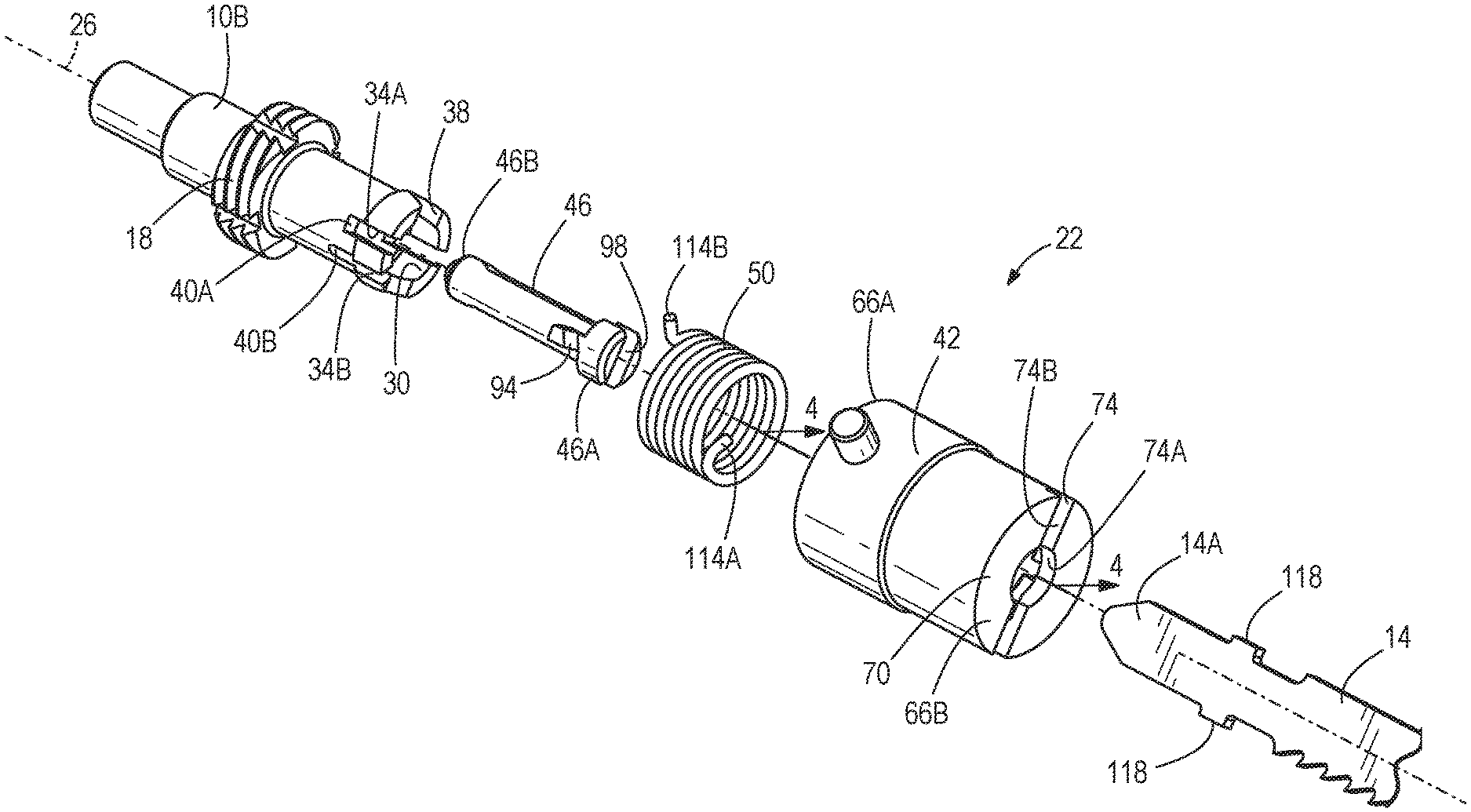
FIG. 2 is an exploded view of the blade clamp of FIG. 1.
FIG. 3 is a cross-sectional view of a cover of the blade clamp of FIG. 1 taken along line 3-3 shown in FIG. 2.
FIG. 4 is a cross-sectional view of the blade clamp of FIG. 1 taken along line 4-4 shown in FIG. 1.
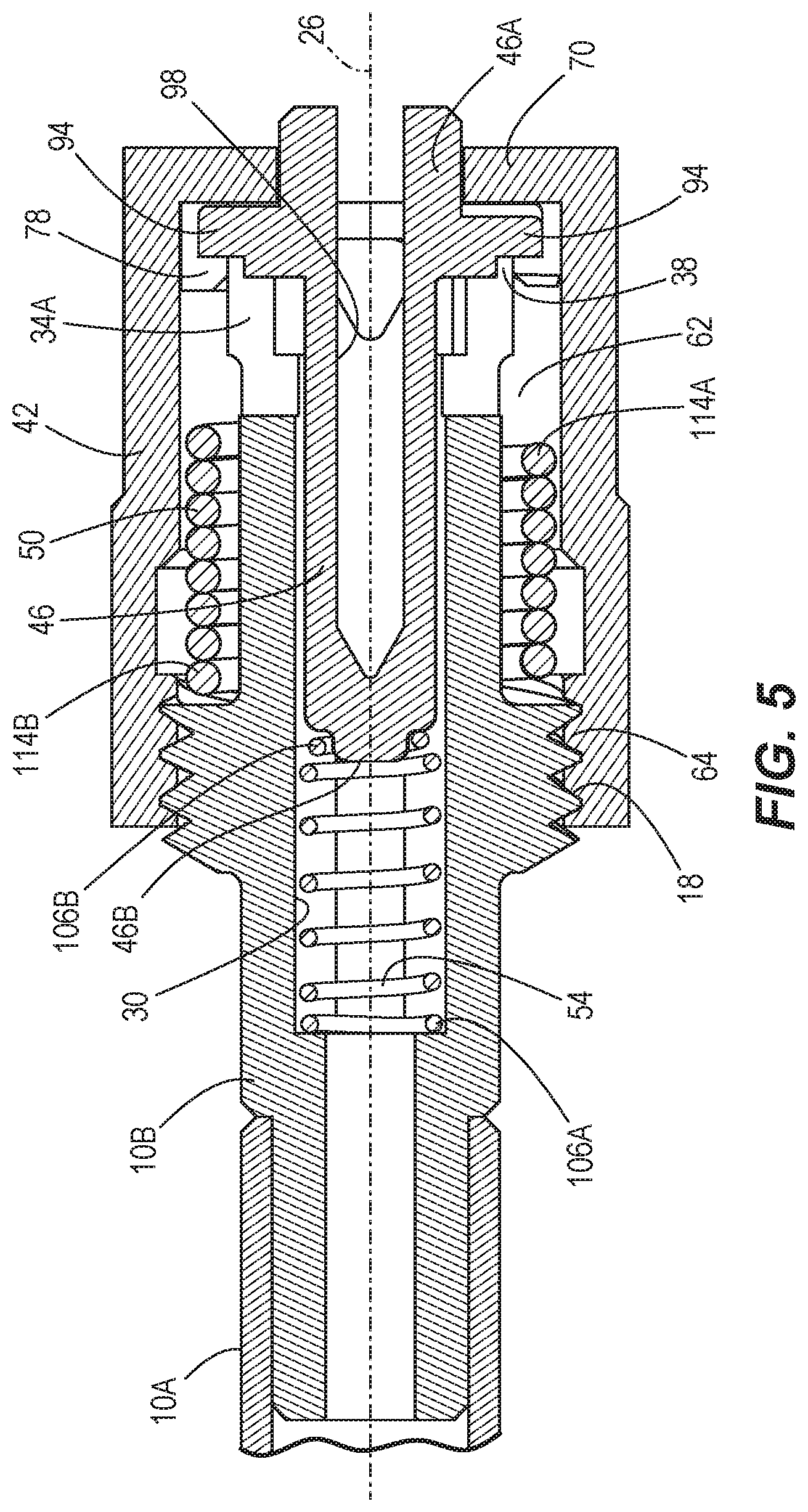
FIG. 5 is a cross-sectional view of the blade clamp of FIG. 1, taken along line 5-5 in FIG. 1, in an unlocked configuration.
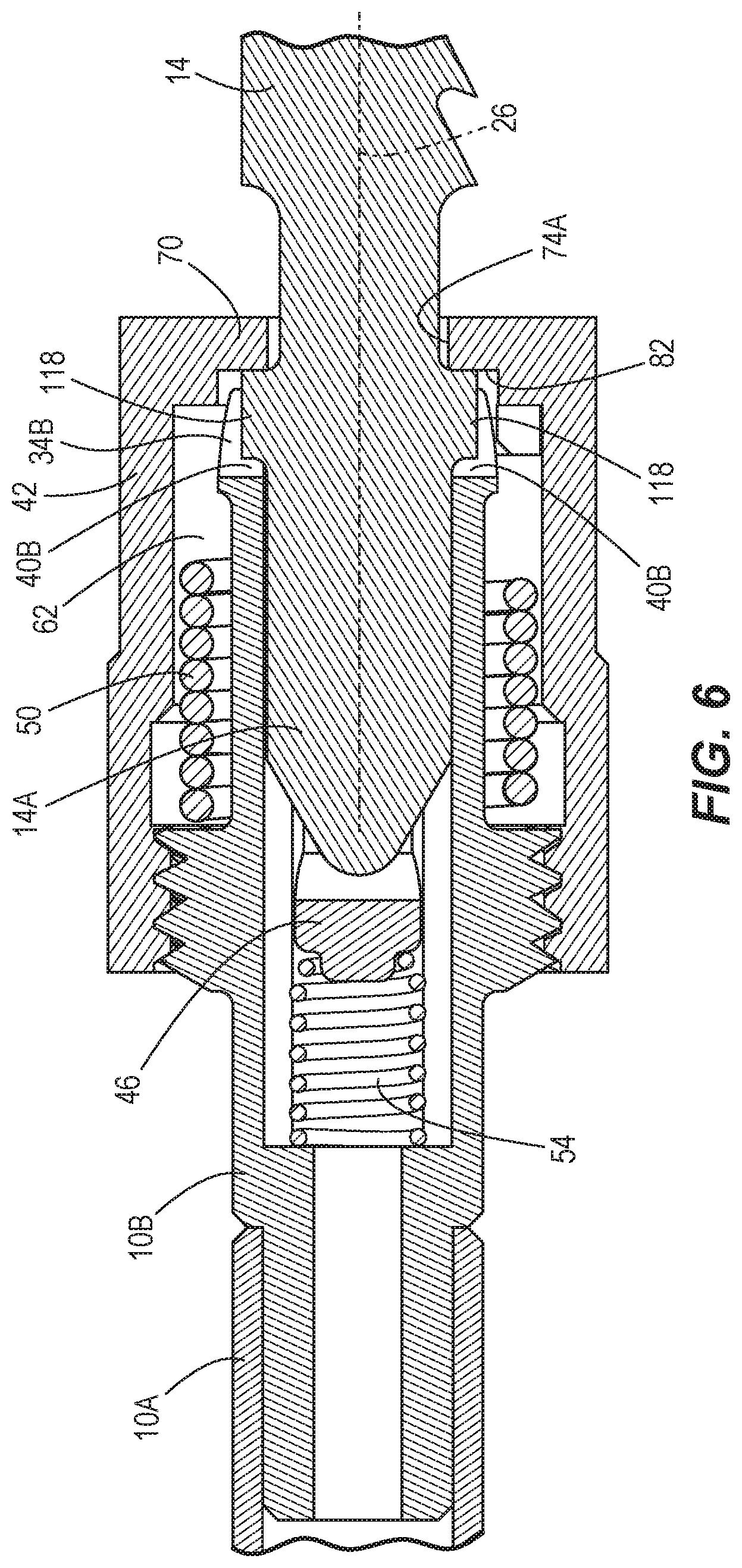
FIG. 6 is another cross-sectional view of the blade clamp of FIG. 5 in a locked configuration.
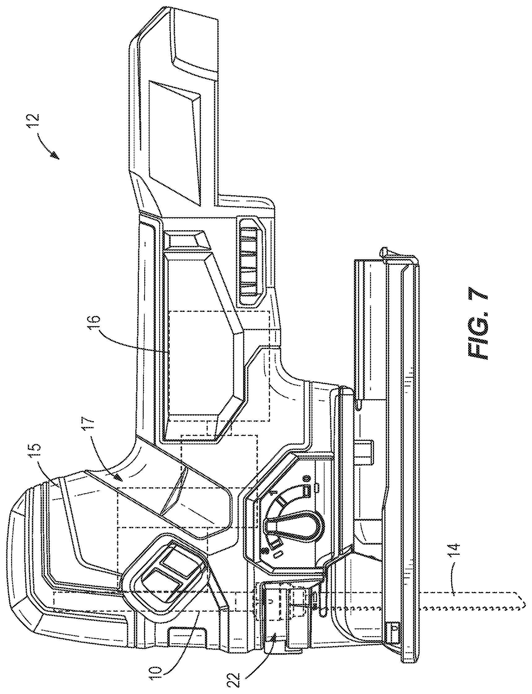
FIG. 7 is a plan view of the power tool in accordance with the embodiment of the invention of FIG. 1.
Before any embodiments of the invention are explained in detail, it is to be understood that the invention is not limited in its application to the details of construction and the arrangement of components set forth in the following description or illustrated in the following drawings. The invention is capable of other embodiments and of being practiced or of being carried out in various ways. Also, it is to be understood that the phraseology and terminology used herein is for the purpose of description and should not be regarded as limiting.
DETAILED DESCRIPTION
FIG. 1 illustrates a spindle 10 of a power tool 12 (FIG. 7), a cutting blade 14, and a blade clamp 22 for selectively securing the blade 14 to the spindle 10. In the illustrated embodiment, as shown in FIG. 7, the power tool 12 is a jigsaw and reciprocating motion is imparted to the spindle 10 and the connected blade 14 for cutting a workpiece. The power tool 12 includes a housing 15 for supporting a motor 16 and a gear train 17 (shown schematically). The spindle 10 is connected to an output of the gear train 17 for relative movement therewith.
With reference to FIGS. 1, 2, and 5, the spindle 10 defines a longitudinal axis 26 extending through the blade clamp 22 and the blade 14. In the illustrated embodiment, the spindle 10 includes a first portion 10A and a separate, second portion 10B partially received within and coupled for co-rotation with the first portion 10A (FIG. 5). The first portion 10A is connectable to a reciprocating mechanism in the jigsaw 12 (e.g., a scotch yoke mechanism). The second portion 10B of the spindle 10 is a body 10B, which is a component of the blade clamp 22, having a plurality of thread segments 18 (FIG. 2) on the outer periphery thereof. The body 10B includes a bore 30 coaxial with the longitudinal axis 26 and two pairs of aligned, laterally spaced notches 34A, 34B that extend radially inward from the outer periphery of the body 10B and communicate with the bore 30 (FIG. 2). The bore 30 and the notches 34A, 34B extend from an end 38 of the body 10B opposite the first portion 10A of the spindle 10 to respective bottom ends 40A, 40B of the notches 34A, 34B. Although the body 10B is a separate portion of the spindle 10 in the illustrated embodiment, the body 10B may alternatively be integrally formed with the spindle 10 as a single piece.
With reference to FIGS. 2-6, the blade clamp 22 also includes a cover 42, an ejection pin 46 positioned within the bore 30, and a torsion spring 50 coupling the body 10B and the cover 42 (FIG. 5). The blade clamp 22 further includes a compression spring 54 positioned within the bore 30 for biasing the ejection pin 46 toward the end 38 of the body 10B.
With continued reference to FIGS. 2-6, the cover 42 has a generally cylindrical shape and includes an inner surface 62 (FIG. 3), a first end 66A, and an opposite second end 66B. The cover 42 includes threads 64 on the inner surface 62 proximate the first end 66A engaged with the thread segments 18 on the body 10B (FIG. 5). The cover 42 includes a face 70 at the second end 66B (FIG. 3). The face 70 includes a slot 74 (FIG. 2) having a first, circular portion 74A, and second, lateral portions 74B extending from opposite sides of the circular portion 74A perpendicular to the longitudinal axis 26. The blade 14 is receivable through the slot 74.
With reference to FIG. 3, the cover 42 further includes multiple internal shoulders 78 proximate the second end 66B and adjacent the face 70. The shoulders 78 extend radially inward from the inner surface 62 and define slots 86 (only one of which is shown in FIG. 3) therebetween. In the illustrated embodiment of the blade clamp 22, the cover 42 includes two slots 86, spaced laterally on opposite sides of the longitudinal axis 26, positioned at an angle of about ninety degrees relative to the slot 74.
With reference to FIGS. 2, 5, and 6, the ejection pin 46 includes two projections 94, spaced laterally on opposite sides of the longitudinal axis 26, extending radially outward. The pin 46 has a generally cylindrical shape and includes a slot 98 (FIGS. 2 and 5) at one end 46A extending along the length of the pin 46. As described in more detail below, the slot 98 is aligned with the slot 74 in the cover 42 when the blade 14 is inserted into the blade clamp 22. With reference to FIG. 5, the cylindrical end 46A of the pin 46 may extend through (i.e., telescope from) the circular portion 74A of the slot 74 beyond the face 70 of the cover 42.
With reference to FIGS. 2 and 4, the projections 94 on the ejection pin 46 are slidably receivable within the respective slots 86 in the interior of the cover 42. Furthermore, the projections 94 are also slidably received in the respective notches 34A in the body 10B, thereby rotationally constraining the pin 46 relative to the body 10B.
With reference to FIG. 5, the compression spring 54 includes opposite ends 106A, 106B. The first end 106A is seated against an internal shoulder that at least partially defines the bore 30, and the second end 106B is seated against an end 46B of the pin 46 opposite the cylindrical end 46A. Therefore, the compression spring 54 biases the pin 46 along the longitudinal axis 26 toward the end 38 of the body 10B. As such, the pin 46 is displaceable within the body 10B in opposite directions along the longitudinal axis 26.
With reference to FIG. 2, the torsion spring 50 includes ends 114A, 114B coupled, respectively, to the body 10B and the cover 42. The torsion spring 50 biases the cover 42 toward a first rotational position relative to the body 10B coinciding with a locked configuration of the blade clamp 22. The cover 42 is rotatable against the bias of the torsion spring 50 toward a second rotational position relative to the body 10B coinciding with an unlocked configuration of the blade clamp 22. Specifically, the torsion spring 50 is configured to rotate the cover 42 about the thread segments 18 such that the cover 42 is also axially displaceable along the body 10B relative to the longitudinal axis 26 when the blade clamp 22 is adjusted between the first and second rotational positions.
With reference to FIG. 2, the blade 14 includes a stem portion 14A and two shoulder portions 118 extending laterally from the stem portion 14A. The stem portion 14A is receivable within the blade clamp 22, specifically through the aligned slots 74, 98 in the cover 42 and the pin 46, respectively. The slot 74 is sufficiently wide (i.e., in a radial direction) for the shoulder portions 118 of the blade 14 to pass completely through the slot 74 for positioning on the interior side of the face 70 (as shown in FIG. 6). The shoulder portions 118 are further receivable in the respective notches 34B (FIG. 2) of the body 10B.
With reference to FIG. 6, in the locked configuration of the blade clamp 22, the slot 74 is rotationally misaligned with the slot 98 in the ejection pin 46 (and the notches 34B in the body 10B), such that the shoulder portions 118 of the blade 14 are positioned adjacent and in contact with an interior surface 82 of the face 70. The blade 14 extends through the circular portion 74A of the slot 74, while the shoulder portions 118 engage the interior surface 82 of the face 70. Furthermore, the axial displacement of the cover 42, as it is moved from the second rotational position to the first rotational position, clamps the shoulder portions 118 between the interior surface 82 and the respective bottom ends 40B of the notches 34B. The compression spring 54 may further bias the shoulder portions 118 against the interior surface 82.
In operation, with reference to FIGS. 5 and 6, the blade clamp 22 is adjustable between an open, unlocked configuration (FIG. 5) and a closed, locked configuration (FIG. 6). When the blade clamp 22 is in the unlocked configuration, the projections 94 on the pin 46 are positioned within the respective slots 86 in the cover 42. Because the pin 46 is rotationally constrained to the body 10B as described above, the projections 94 inhibit rotational movement of the cover 42 when positioned in the slots 86. The compression spring 54 maintains the projections 94 against the interior surface 82 (FIG. 3) of the face 70 for maintaining the blade clamp 22 in the unlocked configuration, in which the slots 74, 98 are rotationally aligned about the longitudinal axis 26 for receiving the stem portion 14A of the blade 14.
During insertion of the stem portion 14A of the blade 14 through the aligned slots 74, 98, continued displacement of the blade 14 in the insertion direction also displaces the ejection pin 46 rearward (i.e., to the left from the frame of reference of FIGS. 5 and 6) along the longitudinal axis 26 against the bias of the spring 54. Subsequently, the projections 94 are removed from the slots 86 in the cover 42, permitting the torsion spring 50 to rebound and rotate the cover 42 from the second rotational position (where the slots 74, 98 are rotationally aligned) toward the first rotational position (where the slots 74, 98 are rotationally misaligned). The slots 34A in the body 10B are longer than the slots 86 in the cover 42, allowing the shoulder portions 118 of the blade 14 to be positioned rearward of the interior surface 82 of the face 70 (FIG. 6). The cover 42 moves axially rearward (i.e., to the left from the frame of reference of FIG. 6) along the body 10B when adjusting to the first rotational position such that the interior surface 82 moves toward the shoulder portions 118. Once the cover 42 has reached its first rotational position and the blade 14 has been released by the user, the shoulder portions 118 are clamped between the interior surface 82 of the face 70 and the bottom ends 40B of the notches 34B for locking the blade clamp 22 in the locked configuration. As such, insertion of the blade 14 by a user automatically adjusts the blade clamp 22 from the unlocked configuration to the locked configuration. Because the blade clamp 22 is normally maintained in the unlocked configuration when a blade 14 is not attached, the blade clamp 22 may allow insertion of the blade 14 by the user only using one hand.
To adjust the blade clamp 22 from the locked configuration to the unlocked configuration, the user rotates the cover 42 from the first rotational position against the bias of the torsional spring 50 toward the second rotational position, axially displacing the interior surface 82 of the face 70 away from the shoulder portions 118, thereby releasing the clamping force on the blade 14. Subsequently, the slots 74, 98 are re-aligned such that the shoulder portions 118 of the shank 14A no longer engage the interior surface 82. The compression spring 54 rebounds to displace the pin 46 forward along the longitudinal axis 26, ejecting the blade 14 from the blade clamp 22 through the slot 74. The projections 94 are again received within the slots 86 in the cover 42 upon the pin 46 reaching its forward-most position within the bore 30, again maintaining the blade clamp 22 in the unlocked configuration.
Various features of the invention are set forth in the following claims.
* * * * *
References
D00000
D00001
D00002
D00003
D00004
D00005
D00006
D00007
XML
uspto.report is an independent third-party trademark research tool that is not affiliated, endorsed, or sponsored by the United States Patent and Trademark Office (USPTO) or any other governmental organization. The information provided by uspto.report is based on publicly available data at the time of writing and is intended for informational purposes only.
While we strive to provide accurate and up-to-date information, we do not guarantee the accuracy, completeness, reliability, or suitability of the information displayed on this site. The use of this site is at your own risk. Any reliance you place on such information is therefore strictly at your own risk.
All official trademark data, including owner information, should be verified by visiting the official USPTO website at www.uspto.gov. This site is not intended to replace professional legal advice and should not be used as a substitute for consulting with a legal professional who is knowledgeable about trademark law.