Surgical robot platform
Crawford , et al. November 17, 2
U.S. patent number 10,835,328 [Application Number 15/704,636] was granted by the patent office on 2020-11-17 for surgical robot platform. This patent grant is currently assigned to Globus Medical, Inc.. The grantee listed for this patent is GLOBUS MEDICAL, INC.. Invention is credited to Neil R. Crawford, Mitchell A. Foster, Nicholas Theodore.


View All Diagrams
| United States Patent | 10,835,328 |
| Crawford , et al. | November 17, 2020 |
Surgical robot platform
Abstract
A medical robot system, including a robot coupled to an effectuator element with the robot configured for controlled movement and positioning. The system may include a transmitter configured to emit one or more signals, and the transmitter is coupled to an instrument coupled to the effectuator element. The system may further include a motor assembly coupled to the robot and a plurality of receivers configured to receive the one or more signals emitted by the transmitter. A control unit is coupled to the motor assembly and the plurality of receivers, and the control unit is configured to supply one or more instruction signals to the motor assembly. The instruction signals can be configured to cause the motor assembly to selectively move the effectuator element.
| Inventors: | Crawford; Neil R. (Chandler, AZ), Theodore; Nicholas (Paradise Valley, AZ), Foster; Mitchell A. (Scottsdale, AZ) | ||||||||||
|---|---|---|---|---|---|---|---|---|---|---|---|
| Applicant: |
|
||||||||||
| Assignee: | Globus Medical, Inc. (Audubon,
PA) |
||||||||||
| Family ID: | 49769457 | ||||||||||
| Appl. No.: | 15/704,636 | ||||||||||
| Filed: | September 14, 2017 |
Prior Publication Data
| Document Identifier | Publication Date | |
|---|---|---|
| US 20180000546 A1 | Jan 4, 2018 | |
Related U.S. Patent Documents
| Application Number | Filing Date | Patent Number | Issue Date | ||
|---|---|---|---|---|---|
| 15609305 | May 31, 2017 | ||||
| 13924505 | Jun 21, 2013 | 9782229 | |||
| 61662702 | Jun 21, 2012 | ||||
| 61800527 | Mar 15, 2013 | ||||
| Current U.S. Class: | 1/1 |
| Current CPC Class: | A61B 34/70 (20160201); A61B 34/76 (20160201); A61B 10/02 (20130101); A61B 10/0233 (20130101); B25J 9/1065 (20130101); A61B 10/0275 (20130101); A61B 17/025 (20130101); A61B 17/1703 (20130101); A61B 90/37 (20160201); A61B 34/32 (20160201); A61M 5/172 (20130101); A61B 34/25 (20160201); A61B 90/14 (20160201); A61B 17/1615 (20130101); A61B 17/8866 (20130101); A61B 50/13 (20160201); A61B 17/7082 (20130101); A61B 34/10 (20160201); A61N 1/0529 (20130101); A61B 46/20 (20160201); A61B 34/20 (20160201); A61B 90/39 (20160201); A61B 17/1671 (20130101); A61B 34/74 (20160201); A61B 34/30 (20160201); A61B 5/066 (20130101); A61B 17/1757 (20130101); A61B 2034/742 (20160201); A61B 2090/3941 (20160201); A61B 2034/2051 (20160201); A61B 2090/3966 (20160201); A61B 2090/3937 (20160201); A61B 2090/3975 (20160201); A61B 2017/00119 (20130101); A61B 2090/3983 (20160201); A61B 2017/00203 (20130101); A61B 2034/301 (20160201); A61B 2090/365 (20160201); A61B 2017/0256 (20130101); A61B 2090/3945 (20160201); A61B 2090/3979 (20160201); A61B 2010/0208 (20130101); A61B 2034/2072 (20160201); A61B 2090/395 (20160201); A61B 2034/741 (20160201); A61B 2034/744 (20160201); A61B 2034/107 (20160201); A61B 2034/2055 (20160201); A61B 2090/3762 (20160201); A61B 2017/00207 (20130101); A61B 2090/374 (20160201); A61B 2034/743 (20160201); A61B 2090/3764 (20160201); A61B 2090/378 (20160201); A61B 2090/064 (20160201); A61B 2090/034 (20160201) |
| Current International Class: | A61B 34/30 (20160101); A61M 5/172 (20060101); A61B 17/70 (20060101); A61B 34/10 (20160101); A61B 17/17 (20060101); A61B 17/88 (20060101); A61B 50/13 (20160101); A61B 46/20 (20160101); A61B 17/02 (20060101); A61B 17/16 (20060101); A61B 34/32 (20160101); A61B 5/06 (20060101); A61B 34/20 (20160101); A61B 10/02 (20060101); A61N 1/05 (20060101); A61B 34/00 (20160101); A61B 90/14 (20160101); A61B 90/00 (20160101); A61B 17/00 (20060101) |
References Cited [Referenced By]
U.S. Patent Documents
| 4150293 | April 1979 | Franke |
| 5086401 | February 1992 | Glassman |
| 5246010 | September 1993 | Gazzara et al. |
| 5354314 | October 1994 | Hardy et al. |
| 5397323 | March 1995 | Taylor et al. |
| 5598453 | January 1997 | Baba et al. |
| 5772594 | June 1998 | Barrick |
| 5791908 | August 1998 | Gillio |
| 5820559 | October 1998 | Ng et al. |
| 5825982 | October 1998 | Wright et al. |
| 5887121 | March 1999 | Funda et al. |
| 5911449 | June 1999 | Daniele et al. |
| 5951475 | September 1999 | Gueziec et al. |
| 5987960 | November 1999 | Messner et al. |
| 6012216 | January 2000 | Esteves et al. |
| 6031888 | February 2000 | Ivan et al. |
| 6033415 | March 2000 | Mittelstadt et al. |
| 6080181 | June 2000 | Jensen et al. |
| 6106511 | August 2000 | Jensen |
| 6122541 | September 2000 | Cosman et al. |
| 6144875 | November 2000 | Schweikard et al. |
| 6157853 | December 2000 | Blume et al. |
| 6167145 | December 2000 | Foley et al. |
| 6167292 | December 2000 | Badano et al. |
| 6201984 | March 2001 | Funda et al. |
| 6203196 | March 2001 | Meyer et al. |
| 6205411 | March 2001 | DiGioia, III et al. |
| 6212419 | April 2001 | Blume et al. |
| 6231565 | May 2001 | Tovey et al. |
| 6236875 | May 2001 | Bucholz et al. |
| 6246900 | June 2001 | Cosman et al. |
| 6276471 | August 2001 | Kratzenberg et al. |
| 6301495 | October 2001 | Gueziec et al. |
| 6306126 | October 2001 | Montezuma |
| 6312435 | November 2001 | Wallace et al. |
| 6314311 | November 2001 | Williams et al. |
| 6320929 | November 2001 | Von Der Haar |
| 6322567 | November 2001 | Mittelstadt et al. |
| 6325808 | December 2001 | Bernard et al. |
| 6340363 | January 2002 | Bolger et al. |
| 6377011 | April 2002 | Ben-Ur |
| 6379302 | April 2002 | Kessman et al. |
| 6402762 | June 2002 | Hunter et al. |
| 6424885 | July 2002 | Niemeyer et al. |
| 6447503 | September 2002 | Wynne et al. |
| 6451027 | September 2002 | Cooper et al. |
| 6477400 | November 2002 | Barrick |
| 6484049 | November 2002 | Seeley et al. |
| 6487267 | November 2002 | Wolter |
| 6490467 | December 2002 | Bucholz et al. |
| 6490475 | December 2002 | Seeley et al. |
| 6499488 | December 2002 | Hunter et al. |
| 6501981 | December 2002 | Schweikard et al. |
| 6507751 | January 2003 | Blume et al. |
| 6535756 | March 2003 | Simon et al. |
| 6560354 | May 2003 | Maurer, Jr. et al. |
| 6565554 | May 2003 | Niemeyer |
| 6587750 | July 2003 | Gerbi et al. |
| 6614453 | September 2003 | Suri et al. |
| 6614871 | September 2003 | Kobiki et al. |
| 6619840 | September 2003 | Rasche et al. |
| 6636757 | October 2003 | Jascob et al. |
| 6645196 | November 2003 | Nixon et al. |
| 6666579 | December 2003 | Jensen |
| 6669635 | December 2003 | Kessman et al. |
| 6701173 | March 2004 | Nowinski et al. |
| 6757068 | June 2004 | Foxlin |
| 6782287 | August 2004 | Grzeszczuk et al. |
| 6783524 | August 2004 | Anderson et al. |
| 6786896 | September 2004 | Madhani et al. |
| 6788018 | September 2004 | Blumenkranz |
| 6804581 | October 2004 | Wang et al. |
| 6823207 | November 2004 | Jensen et al. |
| 6827351 | December 2004 | Graziani et al. |
| 6837892 | January 2005 | Shoham |
| 6839612 | January 2005 | Sanchez et al. |
| 6856826 | February 2005 | Seeley et al. |
| 6856827 | February 2005 | Seeley et al. |
| 6879880 | April 2005 | Nowlin et al. |
| 6892090 | May 2005 | Verard et al. |
| 6920347 | July 2005 | Simon et al. |
| 6922632 | July 2005 | Foxlin |
| 6968224 | November 2005 | Kessman et al. |
| 6978166 | December 2005 | Foley et al. |
| 6988009 | January 2006 | Grimm et al. |
| 6991627 | January 2006 | Madhani et al. |
| 6996487 | February 2006 | Jutras et al. |
| 6999852 | February 2006 | Green |
| 7007699 | March 2006 | Martinelli et al. |
| 7016457 | March 2006 | Senzig et al. |
| 7035716 | April 2006 | Harris |
| 7043961 | May 2006 | Pandey et al. |
| 7062006 | June 2006 | Pelc et al. |
| 7063705 | June 2006 | Young et al. |
| 7072707 | July 2006 | Galloway, Jr. et al. |
| 7083615 | August 2006 | Peterson et al. |
| 7097640 | August 2006 | Wang et al. |
| 7099428 | August 2006 | Clinthorne et al. |
| 7108421 | September 2006 | Gregerson et al. |
| 7130676 | October 2006 | Barrick |
| 7139418 | November 2006 | Abovitz et al. |
| 7139601 | November 2006 | Bucholz et al. |
| 7155316 | December 2006 | Sutherland et al. |
| 7164968 | January 2007 | Treat et al. |
| 7167738 | January 2007 | Schweikard et al. |
| 7169141 | January 2007 | Brock et al. |
| 7172627 | February 2007 | Fiere et al. |
| 7194120 | March 2007 | Wicker et al. |
| 7197107 | March 2007 | Arai et al. |
| 7206626 | April 2007 | Quaid, III |
| 7231014 | June 2007 | Levy |
| 7231063 | June 2007 | Naimark et al. |
| 7239940 | July 2007 | Wang et al. |
| 7248914 | July 2007 | Hastings et al. |
| 7301648 | November 2007 | Foxlin |
| 7302288 | November 2007 | Schellenberg |
| 7313430 | December 2007 | Urquhart et al. |
| 7318805 | January 2008 | Schweikard et al. |
| 7318827 | January 2008 | Leitner et al. |
| 7319897 | January 2008 | Leitner et al. |
| 7324623 | January 2008 | Heuscher et al. |
| 7327865 | February 2008 | Fu et al. |
| 7331967 | February 2008 | Lee et al. |
| 7333642 | February 2008 | Green |
| 7339341 | March 2008 | Oleynikov et al. |
| 7366562 | April 2008 | Dukesherer et al. |
| 7379790 | May 2008 | Toth et al. |
| 7386365 | June 2008 | Nixon |
| 7422592 | September 2008 | Morley et al. |
| 7435216 | October 2008 | Kwon et al. |
| 7440793 | October 2008 | Chauhan et al. |
| 7460637 | December 2008 | Clinthorne et al. |
| 7466303 | December 2008 | Yi et al. |
| 7493153 | February 2009 | Ahmed et al. |
| 7505617 | March 2009 | Fu et al. |
| 7533892 | May 2009 | Schena et al. |
| 7542791 | June 2009 | Mire et al. |
| 7555331 | June 2009 | Viswanathan |
| 7567834 | July 2009 | Clayton et al. |
| 7594912 | September 2009 | Cooper et al. |
| 7606613 | October 2009 | Simon et al. |
| 7607440 | October 2009 | Coste-Maniere et al. |
| 7623902 | November 2009 | Pacheco |
| 7630752 | December 2009 | Viswanathan |
| 7630753 | December 2009 | Simon et al. |
| 7643862 | January 2010 | Schoenefeld |
| 7660623 | February 2010 | Hunter et al. |
| 7661881 | February 2010 | Gregerson et al. |
| 7683331 | March 2010 | Chang |
| 7683332 | March 2010 | Chang |
| 7689320 | March 2010 | Prisco et al. |
| 7691098 | April 2010 | Wallace et al. |
| 7702379 | April 2010 | Avinash et al. |
| 7702477 | April 2010 | Tuemmler et al. |
| 7711083 | May 2010 | Heigl et al. |
| 7711406 | May 2010 | Kuhn et al. |
| 7720523 | May 2010 | Omernick et al. |
| 7725253 | May 2010 | Foxlin |
| 7726171 | June 2010 | Langlotz et al. |
| 7742801 | June 2010 | Neubauer |
| 7751865 | July 2010 | Jascob et al. |
| 7760849 | July 2010 | Zhang |
| 7762825 | July 2010 | Burbank et al. |
| 7763015 | July 2010 | Cooper et al. |
| 7787699 | August 2010 | Mahesh et al. |
| 7796728 | September 2010 | Bergfjord |
| 7813838 | October 2010 | Sommer |
| 7818044 | October 2010 | Dukesherer et al. |
| 7819859 | October 2010 | Prisco et al. |
| 7824401 | November 2010 | Manzo et al. |
| 7831294 | November 2010 | Viswanathan |
| 7834484 | November 2010 | Sailor |
| 7835557 | November 2010 | Kendrick et al. |
| 7835778 | November 2010 | Foley et al. |
| 7835784 | November 2010 | Mire et al. |
| 7840253 | November 2010 | Tremblay et al. |
| 7840256 | November 2010 | Lakin et al. |
| 7843158 | November 2010 | Prisco |
| 7844320 | November 2010 | Shahidi |
| 7853305 | December 2010 | Simon et al. |
| 7853313 | December 2010 | Thompson |
| 7865269 | January 2011 | Prisco et al. |
| D631966 | February 2011 | Perloff et al. |
| 7879045 | February 2011 | Gielen et al. |
| 7881767 | February 2011 | Strommer et al. |
| 7881770 | February 2011 | Melkent et al. |
| 7886743 | February 2011 | Cooper et al. |
| RE42194 | March 2011 | Foley et al. |
| RE42226 | March 2011 | Foley et al. |
| 7900524 | March 2011 | Calloway et al. |
| 7907166 | March 2011 | Lamprecht et al. |
| 7909122 | March 2011 | Schena et al. |
| 7925653 | April 2011 | Saptharishi |
| 7930065 | April 2011 | Larkin et al. |
| 7935130 | May 2011 | Williams |
| 7940999 | May 2011 | Liao et al. |
| 7945012 | May 2011 | Ye et al. |
| 7945021 | May 2011 | Shapiro et al. |
| 7953470 | May 2011 | Vetter et al. |
| 7954397 | June 2011 | Choi et al. |
| 7971341 | July 2011 | Dukesherer et al. |
| 7974674 | July 2011 | Hauck et al. |
| 7974677 | July 2011 | Mire et al. |
| 7974681 | July 2011 | Wallace et al. |
| 7979157 | July 2011 | Anvari |
| 7983733 | July 2011 | Viswanathan |
| 7988215 | August 2011 | Seibold |
| 7996110 | August 2011 | Lipow et al. |
| 8004121 | August 2011 | Sartor |
| 8004229 | August 2011 | Nowlin et al. |
| 8010177 | August 2011 | Csavoy et al. |
| 8010180 | August 2011 | Quaid |
| 8010181 | August 2011 | Smith |
| 8016835 | September 2011 | Birkmeyer |
| 8019045 | September 2011 | Kato |
| 8021310 | September 2011 | Sanborn et al. |
| 8035685 | October 2011 | Jensen |
| 8046054 | October 2011 | Kim et al. |
| 8046057 | October 2011 | Clarke |
| 8052688 | November 2011 | Wolf, II |
| 8054184 | November 2011 | Cline et al. |
| 8054752 | November 2011 | Druke et al. |
| 8057397 | November 2011 | Li et al. |
| 8057407 | November 2011 | Martinelli et al. |
| 8062288 | November 2011 | Cooper et al. |
| 8062375 | November 2011 | Glerum et al. |
| 8066524 | November 2011 | Burbank et al. |
| 8073335 | December 2011 | Labonville et al. |
| 8079950 | December 2011 | Stern et al. |
| 8086299 | December 2011 | Adler et al. |
| 8092370 | January 2012 | Roberts et al. |
| 8098914 | January 2012 | Liao et al. |
| 8100950 | January 2012 | St. Clair et al. |
| 8105320 | January 2012 | Manzo |
| 8108025 | January 2012 | Csavoy et al. |
| 8109877 | February 2012 | Moctezuma de la Barrera et al. |
| 8112292 | February 2012 | Simon |
| 8116430 | February 2012 | Shapiro et al. |
| 8120301 | February 2012 | Goldberg et al. |
| 8121249 | February 2012 | Wang et al. |
| 8123675 | February 2012 | Funda et al. |
| 8133229 | March 2012 | Bonutti |
| 8142420 | March 2012 | Schena |
| 8147494 | April 2012 | Leitner et al. |
| 8150494 | April 2012 | Simon et al. |
| 8150497 | April 2012 | Gielen et al. |
| 8150498 | April 2012 | Gielen et al. |
| 8165658 | April 2012 | Waynik et al. |
| 8170313 | May 2012 | Kendrick et al. |
| 8179073 | May 2012 | Farritor et al. |
| 8182476 | May 2012 | Julian et al. |
| 8182491 | May 2012 | Selover |
| 8184880 | May 2012 | Zhao et al. |
| 8202278 | June 2012 | Orban, III et al. |
| 8208708 | June 2012 | Homan et al. |
| 8208988 | June 2012 | Jensen |
| 8219177 | July 2012 | Smith |
| 8219178 | July 2012 | Smith |
| 8220468 | July 2012 | Cooper et al. |
| 8224024 | July 2012 | Foxlin et al. |
| 8224484 | July 2012 | Swarup et al. |
| 8225798 | July 2012 | Baldwin et al. |
| 8228368 | July 2012 | Zhao et al. |
| 8231610 | July 2012 | Jo et al. |
| 8263933 | July 2012 | Hartmann et al. |
| 8239001 | August 2012 | Verard et al. |
| 8241271 | August 2012 | Millman et al. |
| 8248413 | August 2012 | Gattani et al. |
| 8256319 | September 2012 | Cooper et al. |
| 8271069 | September 2012 | Jascob et al. |
| 8271130 | September 2012 | Hourtash |
| 8281670 | October 2012 | Larkin et al. |
| 8282653 | October 2012 | Nelson et al. |
| 8301226 | October 2012 | Csavoy et al. |
| 8311611 | November 2012 | Csavoy et al. |
| 8320991 | November 2012 | Jascob et al. |
| 8332012 | December 2012 | Kienzle, III |
| 8333755 | December 2012 | Cooper et al. |
| 8335552 | December 2012 | Stiles |
| 8335557 | December 2012 | Maschke |
| 8348931 | January 2013 | Cooper et al. |
| 8353963 | January 2013 | Glerum |
| 8358818 | January 2013 | Miga et al. |
| 8359730 | January 2013 | Burg et al. |
| 8374673 | February 2013 | Adcox et al. |
| 8374723 | February 2013 | Zhao et al. |
| 8379791 | February 2013 | Forthmann et al. |
| 8386019 | February 2013 | Camus et al. |
| 8392022 | March 2013 | Ortmaier et al. |
| 8394099 | March 2013 | Patwardhan |
| 8395342 | March 2013 | Prisco |
| 8398634 | March 2013 | Manzo et al. |
| 8400094 | March 2013 | Schena |
| 8401620 | March 2013 | Velusamy |
| 8414957 | April 2013 | Enzerink et al. |
| 8418073 | April 2013 | Mohr et al. |
| 8450694 | May 2013 | Baviera et al. |
| 8452447 | May 2013 | Nixon |
| RE44305 | June 2013 | Foley et al. |
| 8462911 | June 2013 | Vesel et al. |
| 8465476 | June 2013 | Rogers et al. |
| 8465771 | June 2013 | Wan et al. |
| 8467851 | June 2013 | Mire et al. |
| 8467852 | June 2013 | Csavoy et al. |
| 8469947 | June 2013 | Devengenzo et al. |
| RE44392 | July 2013 | Hynes |
| 8483434 | July 2013 | Buehner et al. |
| 8483800 | July 2013 | Jensen et al. |
| 8486532 | July 2013 | Enzerink et al. |
| 8489235 | July 2013 | Moll et al. |
| 8500722 | August 2013 | Cooper |
| 8500728 | August 2013 | Newton et al. |
| 8504201 | August 2013 | Moll et al. |
| 8506555 | August 2013 | Ruiz Morales |
| 8506556 | August 2013 | Schena |
| 8508173 | August 2013 | Goldberg et al. |
| 8512318 | August 2013 | Tovey et al. |
| 8515576 | August 2013 | Lipow et al. |
| 8518120 | August 2013 | Glerum et al. |
| 8521331 | August 2013 | Itkowitz |
| 8526688 | September 2013 | Groszmann et al. |
| 8526700 | September 2013 | Isaacs |
| 8527094 | September 2013 | Kumar et al. |
| 8528440 | September 2013 | Morley et al. |
| 8532741 | September 2013 | Heruth et al. |
| 8541970 | September 2013 | Nowlin et al. |
| 8548563 | October 2013 | Simon et al. |
| 8549732 | October 2013 | Burg et al. |
| 8551114 | October 2013 | Ramos de la Pena |
| 8551116 | October 2013 | Julian et al. |
| 8556807 | October 2013 | Scott et al. |
| 8556979 | October 2013 | Glerum et al. |
| 8560118 | October 2013 | Green et al. |
| 8561473 | October 2013 | Blumenkranz |
| 8562594 | October 2013 | Cooper et al. |
| 8571638 | October 2013 | Shoham |
| 8571710 | October 2013 | Coste-Maniere et al. |
| 8573465 | November 2013 | Shelton, IV |
| 8574303 | November 2013 | Sharkey et al. |
| 8585420 | November 2013 | Burbank et al. |
| 8594841 | November 2013 | Zhao et al. |
| 8597198 | December 2013 | Sanborn et al. |
| 8600478 | December 2013 | Verard et al. |
| 8603077 | December 2013 | Cooper et al. |
| 8611985 | December 2013 | Lavallee et al. |
| 8613230 | December 2013 | Blumenkranz et al. |
| 8621939 | January 2014 | Blumenkranz et al. |
| 8624537 | January 2014 | Nowlin et al. |
| 8630389 | January 2014 | Kato |
| 8634897 | January 2014 | Simon et al. |
| 8634957 | January 2014 | Toth et al. |
| 8638056 | January 2014 | Goldberg et al. |
| 8638057 | January 2014 | Goldberg et al. |
| 8639000 | January 2014 | Zhao et al. |
| 8641726 | February 2014 | Bonutti |
| 8644907 | February 2014 | Hartmann et al. |
| 8657809 | February 2014 | Schoepp |
| 8660635 | February 2014 | Simon et al. |
| 8666544 | March 2014 | Moll et al. |
| 8675939 | March 2014 | Moctezuma de la Barrera |
| 8678647 | March 2014 | Gregerson et al. |
| 8679125 | March 2014 | Smith et al. |
| 8679183 | March 2014 | Glerum et al. |
| 8682413 | March 2014 | Lloyd |
| 8684253 | April 2014 | Giordano et al. |
| 8685098 | April 2014 | Glerum et al. |
| 8693730 | April 2014 | Umasuthan et al. |
| 8694075 | April 2014 | Groszmann et al. |
| 8696458 | April 2014 | Foxlin et al. |
| 8700123 | April 2014 | Okamura et al. |
| 8706086 | April 2014 | Glerum |
| 8706185 | April 2014 | Foley et al. |
| 8706301 | April 2014 | Zhao et al. |
| 8717430 | May 2014 | Simon et al. |
| 8727618 | May 2014 | Maschke et al. |
| 8734432 | May 2014 | Tuma et al. |
| 8738115 | May 2014 | Amberg et al. |
| 8738181 | May 2014 | Greer et al. |
| 8740882 | June 2014 | Jun et al. |
| 8746252 | June 2014 | McGrogan et al. |
| 8749189 | June 2014 | Nowlin et al. |
| 8749190 | June 2014 | Nowlin et al. |
| 8761930 | June 2014 | Nixon |
| 8764448 | July 2014 | Yang et al. |
| 8771170 | July 2014 | Mesallum et al. |
| 8774901 | July 2014 | Velusamy |
| 8781186 | July 2014 | Clements et al. |
| 8781630 | July 2014 | Banks et al. |
| 8784385 | July 2014 | Boyden et al. |
| 8786241 | July 2014 | Nowlin et al. |
| 8787520 | July 2014 | Baba |
| 8792704 | July 2014 | Isaacs |
| 8798231 | August 2014 | Notohara et al. |
| 8800838 | August 2014 | Shelton, IV |
| 8808164 | August 2014 | Hoffman et al. |
| 8812077 | August 2014 | Dempsey |
| 8814793 | August 2014 | Brabrand |
| 8816628 | August 2014 | Nowlin et al. |
| 8818105 | August 2014 | Myronenko et al. |
| 8820605 | September 2014 | Shelton, IV |
| 8821511 | September 2014 | Von Jako et al. |
| 8823308 | September 2014 | Nowlin et al. |
| 8827996 | September 2014 | Scott et al. |
| 8828024 | September 2014 | Farritor et al. |
| 8830224 | September 2014 | Zhao et al. |
| 8834489 | September 2014 | Cooper et al. |
| 8834490 | September 2014 | Bonutti |
| 8838270 | September 2014 | Druke et al. |
| 8844789 | September 2014 | Shelton, IV et al. |
| 8852210 | October 2014 | Selover |
| 8855822 | October 2014 | Bartol et al. |
| 8858598 | October 2014 | Seifert et al. |
| 8860753 | October 2014 | Bhandarkar et al. |
| 8864751 | October 2014 | Prisco et al. |
| 8864798 | October 2014 | Weiman et al. |
| 8864833 | October 2014 | Glerum et al. |
| 8867703 | October 2014 | Shapiro et al. |
| 8870880 | October 2014 | Himmelberger et al. |
| 8876866 | November 2014 | Zappacosta et al. |
| 8880223 | November 2014 | Raj et al. |
| 8882803 | November 2014 | Iott et al. |
| 8883210 | November 2014 | Truncale et al. |
| 8888821 | November 2014 | Rezach et al. |
| 8888853 | November 2014 | Glerum et al. |
| 8888854 | November 2014 | Glerum et al. |
| 8894652 | November 2014 | Seifert et al. |
| 8894688 | November 2014 | Suh |
| 8894691 | November 2014 | Iott et al. |
| 8906069 | December 2014 | Hansell et al. |
| 8964934 | February 2015 | Ein-Gal |
| 8992580 | March 2015 | Bar et al. |
| 8996169 | March 2015 | Lightcap et al. |
| 9001963 | April 2015 | Sowards-Emmerd et al. |
| 9002076 | April 2015 | Khadem et al. |
| 9044190 | June 2015 | Rubner et al. |
| 9107683 | August 2015 | Hourtash et al. |
| 9125556 | September 2015 | Zehavi et al. |
| 9125690 | September 2015 | Wohlgemuth |
| 9131986 | September 2015 | Greer et al. |
| 9215968 | December 2015 | Schostek et al. |
| 9308050 | April 2016 | Kostrzewski et al. |
| 9380984 | July 2016 | Li et al. |
| 9393039 | July 2016 | Lechner et al. |
| 9398886 | July 2016 | Gregerson et al. |
| 9398890 | July 2016 | Dong et al. |
| 9414859 | August 2016 | Ballard et al. |
| 9420975 | August 2016 | Gutfleisch et al. |
| 9421019 | August 2016 | Plaskos |
| 9492235 | November 2016 | Hourtash et al. |
| 9592096 | March 2017 | Maillet et al. |
| 9750465 | September 2017 | Engel et al. |
| 9757203 | September 2017 | Hourtash et al. |
| 9782229 | October 2017 | Crawford |
| 9795354 | October 2017 | Menegaz et al. |
| 9814535 | November 2017 | Bar et al. |
| 9820783 | November 2017 | Donner et al. |
| 9833265 | November 2017 | Donner et al. |
| 9848922 | December 2017 | Tohmeh et al. |
| 9925011 | March 2018 | Gombert et al. |
| 9931025 | April 2018 | Graetzel et al. |
| 10034717 | July 2018 | Miller et al. |
| 2001/0036302 | November 2001 | Miller |
| 2002/0035321 | March 2002 | Bucholz et al. |
| 2003/0055049 | March 2003 | Brock |
| 2003/0153829 | August 2003 | Sarin et al. |
| 2004/0068172 | April 2004 | Nowinski et al. |
| 2004/0076259 | April 2004 | Jensen et al. |
| 2005/0096502 | May 2005 | Khalili |
| 2005/0143651 | June 2005 | Verard et al. |
| 2005/0171558 | August 2005 | Abovitz et al. |
| 2005/0245820 | November 2005 | Sarin |
| 2006/0100610 | May 2006 | Wallace et al. |
| 2006/0142657 | June 2006 | Quaid |
| 2006/0173329 | August 2006 | Marquart et al. |
| 2006/0184396 | August 2006 | Dennis et al. |
| 2006/0241416 | October 2006 | Marquart et al. |
| 2006/0291612 | December 2006 | Nishide et al. |
| 2007/0015987 | January 2007 | Benlloch Baviera et al. |
| 2007/0021738 | January 2007 | Nasser et al. |
| 2007/0038059 | February 2007 | Sheffer et al. |
| 2007/0055291 | March 2007 | Birkmeyer |
| 2007/0073133 | March 2007 | Schoenefeld |
| 2007/0156121 | July 2007 | Millman et al. |
| 2007/0156157 | July 2007 | Nahum et al. |
| 2007/0167712 | July 2007 | Keglovich et al. |
| 2007/0233238 | October 2007 | Huynh et al. |
| 2007/0238985 | October 2007 | Smith |
| 2007/0265527 | November 2007 | Wohlgemuth |
| 2007/0270690 | November 2007 | Woerlein |
| 2008/0004523 | January 2008 | Jensen |
| 2008/0004603 | January 2008 | Larkin |
| 2008/0013809 | January 2008 | Zhu et al. |
| 2008/0033283 | February 2008 | Dellaca et al. |
| 2008/0046122 | February 2008 | Manzo et al. |
| 2008/0082109 | April 2008 | Moll et al. |
| 2008/0091101 | April 2008 | Velusamy |
| 2008/0108912 | May 2008 | Node-Langlois |
| 2008/0108991 | May 2008 | Von Jako |
| 2008/0109012 | May 2008 | Falco et al. |
| 2008/0144906 | June 2008 | Allred et al. |
| 2008/0154389 | June 2008 | Smith |
| 2008/0161680 | July 2008 | Von Jako et al. |
| 2008/0161682 | July 2008 | Kendrick et al. |
| 2008/0177203 | July 2008 | von Jako |
| 2008/0214922 | September 2008 | Hartmann et al. |
| 2008/0215181 | September 2008 | Smith |
| 2008/0228068 | September 2008 | Viswanathan et al. |
| 2008/0228196 | September 2008 | Wang et al. |
| 2008/0235052 | September 2008 | Node-Langlois et al. |
| 2008/0255445 | October 2008 | Neubauer |
| 2008/0269596 | October 2008 | Revie et al. |
| 2008/0287771 | November 2008 | Anderson |
| 2008/0287781 | November 2008 | Revie et al. |
| 2008/0300477 | December 2008 | Lloyd et al. |
| 2008/0300478 | December 2008 | Zuhars et al. |
| 2008/0302950 | December 2008 | Park et al. |
| 2008/0306490 | December 2008 | Lakin et al. |
| 2008/0319311 | December 2008 | Hamadeh |
| 2009/0012509 | January 2009 | Csavoy et al. |
| 2009/0030428 | January 2009 | Omori et al. |
| 2009/0080737 | March 2009 | Battle et al. |
| 2009/0185655 | July 2009 | Koken et al. |
| 2009/0198121 | August 2009 | Hoheisel |
| 2009/0216113 | August 2009 | Meier et al. |
| 2009/0228019 | September 2009 | Gross et al. |
| 2009/0259123 | October 2009 | Navab et al. |
| 2009/0259230 | October 2009 | Khadem et al. |
| 2009/0264899 | October 2009 | Appenrodt et al. |
| 2009/0281417 | November 2009 | Hartmann et al. |
| 2010/0022874 | January 2010 | Wang et al. |
| 2010/0039506 | February 2010 | Sarvestani et al. |
| 2010/0125286 | May 2010 | Wang et al. |
| 2010/0130986 | May 2010 | Mailloux et al. |
| 2010/0228117 | September 2010 | Hartmann |
| 2010/0228265 | September 2010 | Prisco |
| 2010/0249571 | September 2010 | Jensen et al. |
| 2010/0274120 | October 2010 | Heuscher |
| 2010/0280363 | November 2010 | Skarda et al. |
| 2010/0331858 | December 2010 | Simaan et al. |
| 2011/0022229 | January 2011 | Jang et al. |
| 2011/0077504 | March 2011 | Fischer et al. |
| 2011/0098553 | April 2011 | Robbins et al. |
| 2011/0130761 | June 2011 | Plaskos |
| 2011/0137152 | June 2011 | Li |
| 2011/0213384 | September 2011 | Jeong |
| 2011/0224684 | September 2011 | Larkin et al. |
| 2011/0224685 | September 2011 | Larkin et al. |
| 2011/0224686 | September 2011 | Larkin et al. |
| 2011/0224687 | September 2011 | Larkin et al. |
| 2011/0224688 | September 2011 | Larkin et al. |
| 2011/0224689 | September 2011 | Larkin et al. |
| 2011/0224825 | September 2011 | Larkin et al. |
| 2011/0230967 | September 2011 | O'Halloran et al. |
| 2011/0238080 | September 2011 | Ranjit et al. |
| 2011/0276058 | November 2011 | Choi et al. |
| 2011/0282189 | November 2011 | Graumann |
| 2011/0286573 | November 2011 | Schretter et al. |
| 2011/0295062 | December 2011 | Gratacos Solsona et al. |
| 2011/0295370 | December 2011 | Suh et al. |
| 2011/0306986 | December 2011 | Lee et al. |
| 2012/0035507 | February 2012 | George et al. |
| 2012/0046668 | February 2012 | Gantes |
| 2012/0051498 | March 2012 | Koishi |
| 2012/0053597 | March 2012 | Anvari et al. |
| 2012/0059248 | March 2012 | Holsing et al. |
| 2012/0071753 | March 2012 | Hunter et al. |
| 2012/0108954 | May 2012 | Schulhauser et al. |
| 2012/0109150 | May 2012 | Quaid |
| 2012/0136372 | May 2012 | Amat Girbau et al. |
| 2012/0143084 | June 2012 | Shoham |
| 2012/0184839 | July 2012 | Woerlein |
| 2012/0197182 | August 2012 | Millman et al. |
| 2012/0209290 | August 2012 | Selover |
| 2012/0226145 | September 2012 | Chang et al. |
| 2012/0235909 | September 2012 | Birkenbach et al. |
| 2012/0245596 | September 2012 | Meenink |
| 2012/0253332 | October 2012 | Moll |
| 2012/0253360 | October 2012 | White et al. |
| 2012/0256092 | October 2012 | Zingerman |
| 2012/0294498 | November 2012 | Popovic |
| 2012/0296203 | November 2012 | Hartmann et al. |
| 2013/0006267 | January 2013 | Odermatt et al. |
| 2013/0016889 | January 2013 | Myronenko et al. |
| 2013/0030571 | January 2013 | Ruiz Morales et al. |
| 2013/0035583 | February 2013 | Park et al. |
| 2013/0060146 | March 2013 | Yang et al. |
| 2013/0060337 | March 2013 | Petersheim et al. |
| 2013/0094742 | April 2013 | Feilkas |
| 2013/0096574 | April 2013 | Kang et al. |
| 2013/0113791 | May 2013 | Isaacs et al. |
| 2013/0116706 | May 2013 | Lee et al. |
| 2013/0131695 | May 2013 | Scarfogliero et al. |
| 2013/0144307 | June 2013 | Jeong et al. |
| 2013/0158542 | June 2013 | Manzo et al. |
| 2013/0165937 | June 2013 | Patwardhan |
| 2013/0178867 | July 2013 | Farritor et al. |
| 2013/0178868 | July 2013 | Roh |
| 2013/0178870 | July 2013 | Schena |
| 2013/0184572 | July 2013 | Velusamy |
| 2013/0204271 | August 2013 | Brisson et al. |
| 2013/0211419 | August 2013 | Jensen |
| 2013/0211420 | August 2013 | Jensen |
| 2013/0218142 | August 2013 | Tuma et al. |
| 2013/0223702 | August 2013 | Holsing et al. |
| 2013/0225942 | August 2013 | Holsing et al. |
| 2013/0225943 | August 2013 | Holsing et al. |
| 2013/0231556 | September 2013 | Holsing et al. |
| 2013/0237995 | September 2013 | Lee et al. |
| 2013/0245375 | September 2013 | DiMaio et al. |
| 2013/0261640 | October 2013 | Kim et al. |
| 2013/0272488 | October 2013 | Bailey et al. |
| 2013/0272489 | October 2013 | Dickman et al. |
| 2013/0274761 | October 2013 | Devengenzo et al. |
| 2013/0281821 | October 2013 | Liu et al. |
| 2013/0296884 | November 2013 | Taylor et al. |
| 2013/0303887 | November 2013 | Holsing et al. |
| 2013/0307955 | November 2013 | Deitz et al. |
| 2013/0317521 | November 2013 | Choi et al. |
| 2013/0325033 | December 2013 | Schena et al. |
| 2013/0325035 | December 2013 | Hauck et al. |
| 2013/0331686 | December 2013 | Freysinger et al. |
| 2013/0331858 | December 2013 | Devengenzo et al. |
| 2013/0331861 | December 2013 | Yoon |
| 2013/0342578 | December 2013 | Isaacs |
| 2013/0345717 | December 2013 | Markvicka et al. |
| 2013/0345718 | December 2013 | Crawford |
| 2013/0345757 | December 2013 | Stad |
| 2014/0001235 | January 2014 | Shelton, IV |
| 2014/0012131 | January 2014 | Heruth et al. |
| 2014/0031664 | January 2014 | Kang et al. |
| 2014/0046128 | February 2014 | Lee et al. |
| 2014/0046132 | February 2014 | Hoeg et al. |
| 2014/0046340 | February 2014 | Wilson et al. |
| 2014/0049629 | February 2014 | Siewerdsen et al. |
| 2014/0058406 | February 2014 | Tsekos |
| 2014/0066944 | March 2014 | Taylor et al. |
| 2014/0073914 | March 2014 | Lavallee et al. |
| 2014/0080086 | March 2014 | Chen |
| 2014/0081128 | March 2014 | Verard et al. |
| 2014/0088612 | March 2014 | Bartol et al. |
| 2014/0094694 | April 2014 | Moctezuma de la Barrera |
| 2014/0094851 | April 2014 | Gordon |
| 2014/0096369 | April 2014 | Matsumoto et al. |
| 2014/0100587 | April 2014 | Farritor et al. |
| 2014/0121676 | May 2014 | Kostrzewski et al. |
| 2014/0128882 | May 2014 | Kwak et al. |
| 2014/0135796 | May 2014 | Simon et al. |
| 2014/0142591 | May 2014 | Alvarez et al. |
| 2014/0142592 | May 2014 | Moon et al. |
| 2014/0148692 | May 2014 | Hartmann et al. |
| 2014/0163581 | June 2014 | Devengenzo et al. |
| 2014/0171781 | June 2014 | Stiles |
| 2014/0171900 | June 2014 | Stiles |
| 2014/0171965 | June 2014 | Loh et al. |
| 2014/0180308 | June 2014 | von Grunberg |
| 2014/0180309 | June 2014 | Seeber et al. |
| 2014/0187915 | July 2014 | Yaroshenko et al. |
| 2014/0188132 | July 2014 | Kang |
| 2014/0194699 | July 2014 | Roh et al. |
| 2014/0130810 | August 2014 | Azizian et al. |
| 2014/0221819 | August 2014 | Sarment |
| 2014/0222023 | August 2014 | Kim et al. |
| 2014/0228631 | August 2014 | Kwak et al. |
| 2014/0234804 | August 2014 | Huang et al. |
| 2014/0257328 | September 2014 | Kim et al. |
| 2014/0257329 | September 2014 | Jang et al. |
| 2014/0257330 | September 2014 | Choi et al. |
| 2014/0275760 | September 2014 | Lee et al. |
| 2014/0275955 | September 2014 | Crawford et al. |
| 2014/0275985 | September 2014 | Walker et al. |
| 2014/0276931 | September 2014 | Parihar et al. |
| 2014/0276940 | September 2014 | Seo |
| 2014/0276944 | September 2014 | Farritor et al. |
| 2014/0288413 | September 2014 | Hwang et al. |
| 2014/0299648 | October 2014 | Shelton, IV et al. |
| 2014/0303434 | October 2014 | Farritor et al. |
| 2014/0303643 | October 2014 | Ha et al. |
| 2014/0305995 | October 2014 | Shelton, IV et al. |
| 2014/0309659 | October 2014 | Roh et al. |
| 2014/0316436 | October 2014 | Bar et al. |
| 2014/0323803 | October 2014 | Hoffman et al. |
| 2014/0324070 | October 2014 | Min et al. |
| 2014/0330288 | November 2014 | Date et al. |
| 2014/0364720 | December 2014 | Darrow et al. |
| 2014/0371577 | December 2014 | Maillet et al. |
| 2014/0379130 | December 2014 | Lee et al. |
| 2015/0039034 | February 2015 | Frankel et al. |
| 2015/0085970 | March 2015 | Bouhnik et al. |
| 2015/0146847 | May 2015 | Liu |
| 2015/0150524 | June 2015 | Yorkston et al. |
| 2015/0196261 | July 2015 | Funk |
| 2015/0213633 | July 2015 | Chang et al. |
| 2015/0335480 | November 2015 | Alvarez et al. |
| 2015/0342647 | December 2015 | Frankel et al. |
| 2016/0005194 | January 2016 | Schretter et al. |
| 2016/0166329 | June 2016 | Langan et al. |
| 2016/0235480 | August 2016 | Scholl et al. |
| 2016/0242849 | August 2016 | Crawford |
| 2016/0249990 | September 2016 | Glozman et al. |
| 2016/0302871 | October 2016 | Gregerson et al. |
| 2016/0320322 | November 2016 | Suzuki |
| 2016/0331335 | November 2016 | Gregerson et al. |
| 2017/0135770 | May 2017 | Scholl et al. |
| 2017/0143284 | May 2017 | Sehnert et al. |
| 2017/0143426 | May 2017 | Isaacs et al. |
| 2017/0156816 | June 2017 | Ibrahim |
| 2017/0202629 | July 2017 | Maillet et al. |
| 2017/0212723 | July 2017 | Atarot et al. |
| 2017/0215825 | August 2017 | Johnson et al. |
| 2017/0215826 | August 2017 | Johnson et al. |
| 2017/0215827 | August 2017 | Johnson et al. |
| 2017/0231702 | August 2017 | Crawford |
| 2017/0231710 | August 2017 | Scholl et al. |
| 2017/0239002 | August 2017 | Crawford |
| 2017/0239003 | August 2017 | Crawford |
| 2017/0239006 | August 2017 | Crawford |
| 2017/0239007 | August 2017 | Crawford |
| 2017/0245944 | August 2017 | Crawford |
| 2017/0245951 | August 2017 | Crawford |
| 2017/0252112 | September 2017 | Crawford |
| 2017/0258426 | September 2017 | Risher-Kelly et al. |
| 2017/0258533 | September 2017 | Crawford |
| 2017/0273748 | September 2017 | Hourtash et al. |
| 2017/0281145 | October 2017 | Crawford |
| 2017/0296277 | October 2017 | Hourtash et al. |
| 2017/0360493 | December 2017 | Zucher et al. |
| 2017/0360517 | December 2017 | Crawford |
| 2286729 | Feb 2011 | EP | |||
| 898843 | Apr 1996 | JP | |||
| 8313304 | Nov 1996 | JP | |||
| 02071369 | Sep 2002 | WO | |||
Other References
|
US 8,231,638 B2, 07/2012, Swarup et al. (withdrawn) cited by applicant. |
Primary Examiner: Hoffa; Angela M
Parent Case Text
RELATED APPLICATIONS
This application is a continuation application of U.S. patent application Ser. No. 15/609,305 filed on May 31, 2017, which is a continuation application of U.S. patent application Ser. No. 13/924,505 filed on Jun. 21, 2013 (published as U.S. Patent Publication No. 2016-0242849), both of which are incorporated herein by reference in their entirety for all purposes. Application Ser. No. 13/924,505 claims priority to U.S. Provisional Pat. App. No. 61/662,702 filed Jun. 21, 2012 and U.S. Provisional Pat. App. No. 61/800,527 filed Mar. 15, 2013, which are incorporated herein by reference in their entireties for all purposes.
Claims
What is claimed is:
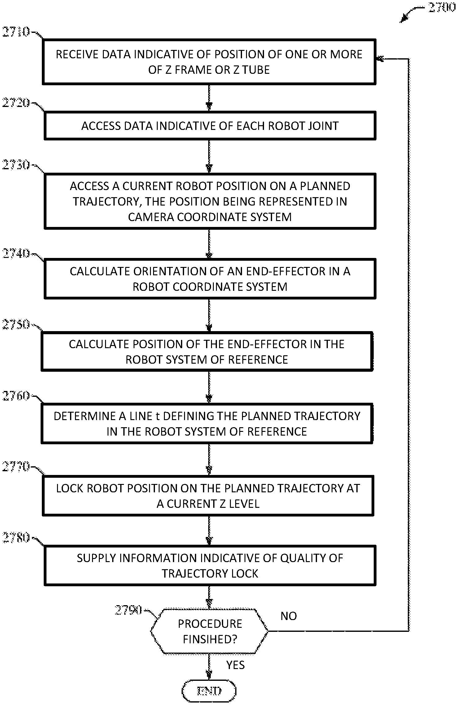
1. A method for automatically maintaining an end effectuator of a surgical robot on a planned trajectory to a surgical site, said method comprising: receiving data indicative of a position of the end effectuator in a robot coordinate system, wherein the position is about an orientation axis associated with the end effectuator; accessing data indicative of one or more joints of the surgical robot; accessing a current camera position of the end effectuator on the planned trajectory, wherein the current position is represented in a camera coordinate system; calculating an orientation of the end effectuator in the robot coordinate system; calculating a position of the end effectuator in the robot coordinate system; determining a line defining the planned trajectory in the robot coordinate system; and locking a position of the end effectuator on the planned trajectory, wherein the surgical robot includes a base, and a robot arm configured to be coupled to the end effectuator, wherein the robot arm is configured to independently move the end effectuator along the x, y, and z axes and configured for selective rotation about one of the x, y, and z axes, and wherein the robot arm does not provide six degrees of freedom, wherein the robot arm is configured to move on a cartesian positioning system, wherein movements of the robot arm occur in different axes independently of one another.
2. The method of claim 1, further comprising supplying information indicative of the locked position of the surgical robot.
3. The method of claim 2, further comprising determining whether a surgical procedure is finished.
4. The method of claim 1, wherein supplying information includes providing aural indicia.
5. The method of claim 3, wherein the planned trajectory is generated by an operator.
6. The method of claim 5, wherein the planned trajectory is retained in a memory of a computing device.
7. The method of claim 6, wherein data indicative of each of the one or more joints of the surgical robot includes an encoder count from each axis motor of the surgical robot.
8. The method of claim 1, further comprising displaying the planned trajectory on a display associated with the surgical robot.
9. A method for automatically maintaining an end effectuator of a surgical robot on a planned trajectory, the surgical robot comprising a display and a housing, wherein the housing further comprises a robot arm and the end effectuator, said method comprising: receiving data indicative of an orientation position of the end effectuator in a robot coordinate system, wherein the orientation position is about an orientation axis associated with the end effectuator; accessing data indicative of one or more joints of the surgical robot; accessing a current camera position of the end effectuator of the surgical robot on the planned trajectory, wherein the current position is represented in a camera coordinate system; calculating an orientation of the end effectuator in the robot coordinate system; calculating a position of the end effectuator in the robot coordinate system; determining a line defining the planned trajectory of the end effectuator in the robot coordinate system; and locking a position of the end effectuator of the surgical robot on the planned trajectory, wherein the robot arm is configured to independently move the end effectuator along the x, y, and z axes and configured for selective rotation about one of the x, y, and z axes, and wherein the robot arm does not provide six degrees of freedom, wherein the planned trajectory is a trajectory to a pedicle portion of the spine wherein the robot arm is configured to move on a cartesian positioning system, wherein movements of the robot arm occur in different axes independently of one another.
10. The method of claim 9, further comprising supplying information indicative of the locked position of the end effectuator of the surgical robot.
11. The method of claim 10, further comprising determining whether a surgical procedure is finished.
12. The method of claim 11, wherein the planned trajectory is generated by an operator.
13. The method of claim 12, wherein the planned trajectory is retained in a memory of a computing device.
14. The method of claim 13, wherein data indicative of each of the one or more joints of the surgical arm includes an encoder count from each axis motor of the surgical robot.
15. The method of claim 9, wherein supplying information includes providing aural indicia.
16. The method of claim 9, further comprising displaying the planned trajectory on the display.
Description
BACKGROUND
Various medical procedures require the precise localization of a three-dimensional position of a surgical instrument within the body in order to effect optimized treatment. Limited robotic assistance for surgical procedures is currently available. One of the characteristics of many of the current robots used in surgical applications which make them error prone is that they use an articular arm based on a series of rotational joints. The use of an articular system may create difficulties in arriving at an accurately targeted location because the level of any error is increased over each joint in the articular system.
SUMMARY
Some embodiments of the invention provide a surgical robot (and optionally an imaging system) that utilizes a Cartesian positioning system that allows movement of a surgical instrument to be individually controlled in an x-axis, y-axis and z-axis. In some embodiments, the surgical robot can include a base, a robot arm coupled to and configured for articulation relative to the base, as well as an end-effectuator coupled to a distal end of the robot arm. The effectuator element can include the surgical instrument or can be configured for operative coupling to the surgical instrument. Some embodiments of the invention allow the roll, pitch and yaw rotation of the end-effectuator and/or surgical instrument to be controlled without creating movement along the x-axis, y-axis, or z-axis.
DESCRIPTION OF THE DRAWINGS
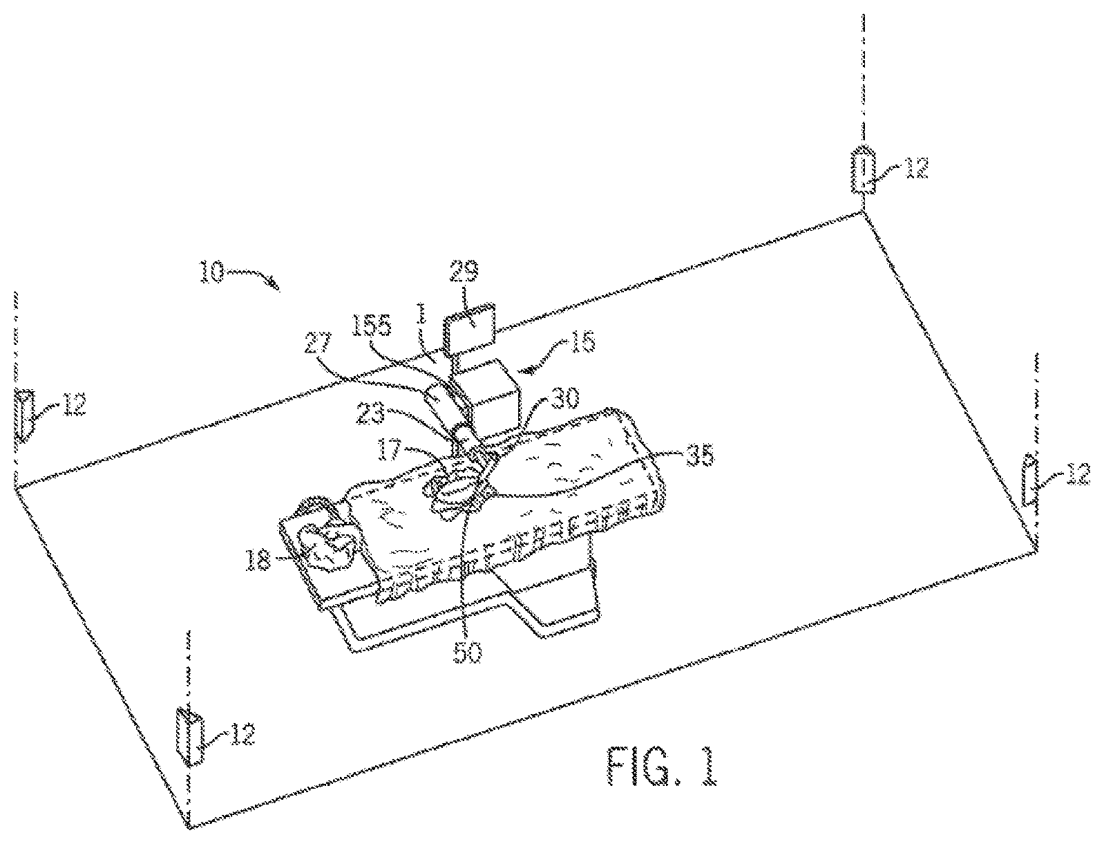
FIG. 1 is a partial perspective view of a room in which a medical procedure is taking place by using a surgical robot.
FIG. 2 is a perspective view of a surgical robot according to an embodiment of the invention.
FIGS. 3A-3B are perspective views of the surgical robot illustrated in FIG. 2, which show the movement of the base of the surgical robot in the z-axis direction in accordance with an embodiment of the invention.
FIG. 4 is a partial perspective view of the surgical robot of FIG. 2 which shows how the robot arm can be moved in the x-axis direction.
FIGS. 5A-5B are partial perspective views of the surgical robot of FIG. 2, which show how the robot arm can be moved in the y-axis direction.
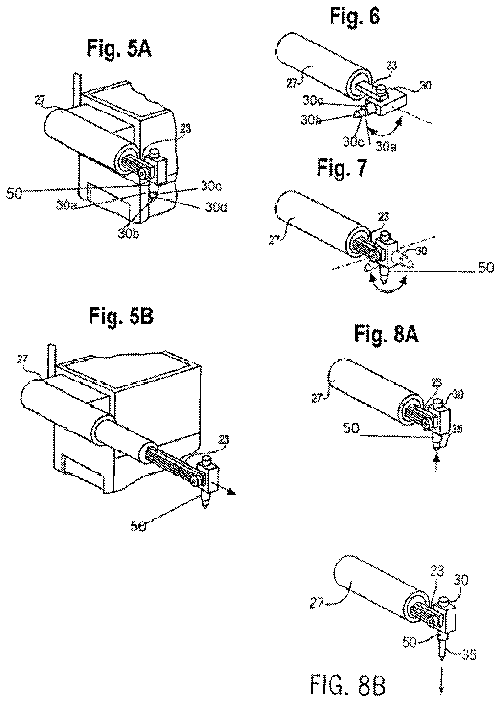
FIG. 6 is a perspective view of a portion of the robot arm of FIG. 2 showing how an effectuator element can be twisted about a y-axis.
FIG. 7 is a perspective view of a portion of a robot arm of FIG. 2 showing how an effectuator element can be pivoted about a pivot axis that is perpendicular to the y-axis.
FIGS. 8A-8B are partial perspective views of the surgical robot of FIG. 2, which show the movement of a surgical instrument 35 along the z-axis from an effectuator element.
FIG. 9 is a system diagram which shows local positioning sensors, a controlling PC, and a Radiofrequency (RF) transmitter in accordance with an embodiment of the invention.
FIG. 10 is a system diagram of the controlling PC, user input, and motors for controlling the robot in accordance with an embodiment of the invention.
FIG. 11 is a flow chart diagram for general operation of a surgical robot in accordance with one embodiment of the invention.
FIG. 12 is a flow chart diagram for a closed screw/needle insertion performed using a surgical robot in accordance with one embodiment of the invention.
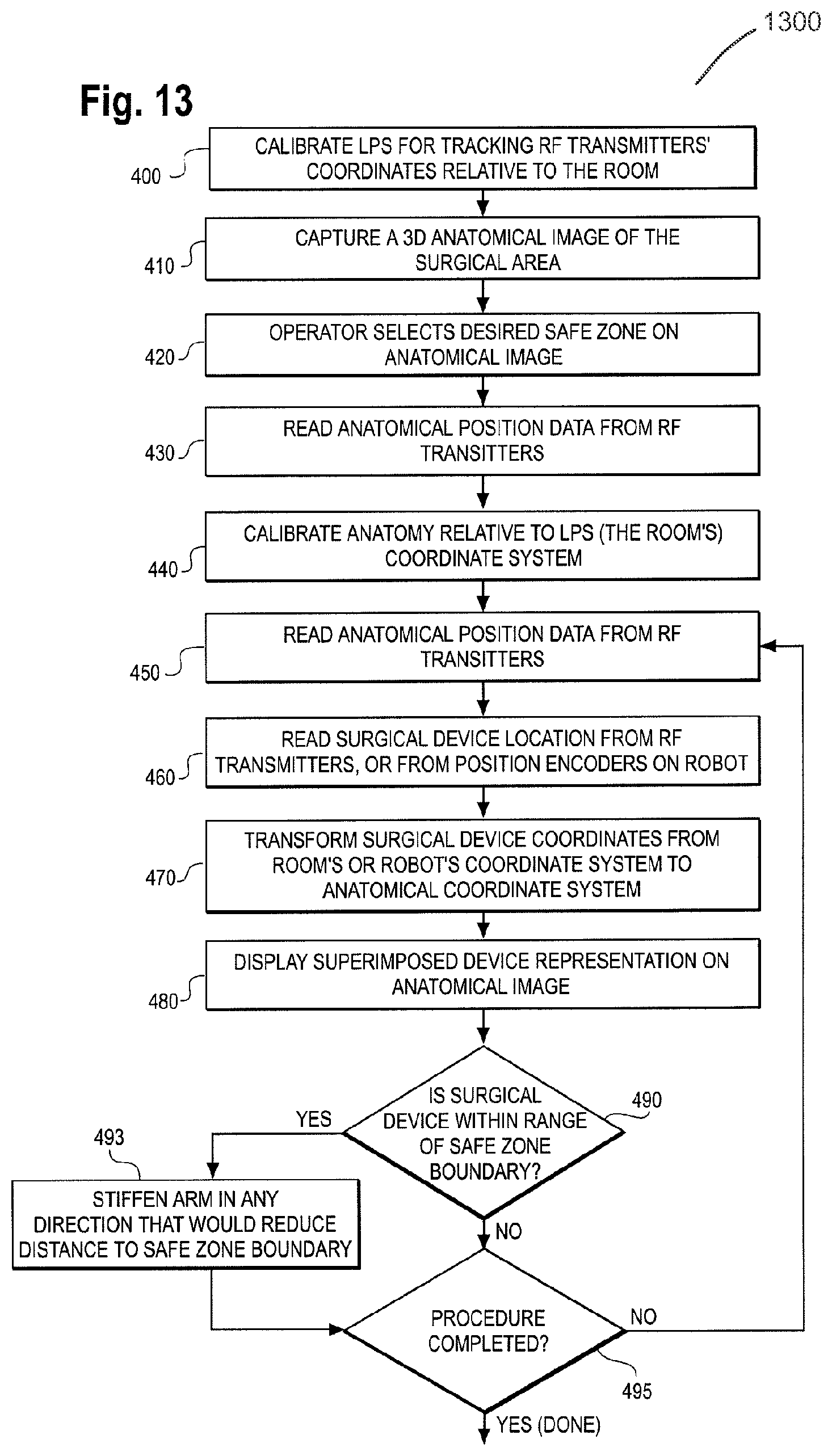
FIG. 13 is a flow chart diagram of a safe zone surgery performed using a surgical robot as described herein in accordance with one embodiment of the invention.
FIG. 14 is a flow chart diagram of a flexible catheter insertion procedure performed using a surgical robot as described herein in accordance with one embodiment of the invention.
FIG. 15A shows a screenshot of a monitor display showing a set up of the anatomy in X, Y and Z views in accordance with one embodiment of the invention.
FIG. 15B shows a screenshot of a monitor display showing what the user views during an invasive procedure in accordance with one embodiment of the invention.
FIG. 16 depicts a surgical robot having a plurality of optical markers mounted for tracking movement in an x-direction in accordance with one embodiment of the invention.
FIGS. 17A-17B depict surgical instruments having a stop mechanism in accordance with one embodiment of the invention.
FIGS. 17C-17E illustrate tools for manually adjusting a drill stop with reference to drill bit markings in accordance with one embodiment of the invention.
FIGS. 17F-17J illustrate tools for locking and holding a drill bit in a set position in accordance with one embodiment of the invention.
FIGS. 18A-18B depicts an end-effectuator having a clearance mechanism in accordance with one embodiment of the invention.
FIG. 19A-19B depicts an end-effectuator having an attachment element for applying distraction and/or compression forces in accordance with one embodiment of the invention.
FIGS. 20A-20E show the use of calibration frames with the guidance system in accordance with one embodiment of the invention.
FIG. 21A depicts flexible roll configurations of a targeting fixture in accordance with one embodiment of the invention.
FIG. 21B shows possible positions of markers along a line in space in accordance with one embodiment of the invention.
FIG. 21C depicts flexible roll configurations of a targeting fixture in accordance with one embodiment of the invention.
FIG. 21D shows a fixture that can be employed to provide desired stiffness to the unrolled fixture such that it maintains its position after unrolling occurs in accordance with one embodiment of the invention.
FIGS. 22A-22D depict a targeting fixture and method configured for application to the skull of a patient in accordance with one embodiment of the invention.
FIG. 23 depicts a dynamic tracking device mounted to the spinous process of the lumbar spine of a patient in accordance with one embodiment of the invention.
FIGS. 24-27 illustrate methods for the robot in accordance with one embodiment of the invention.
FIGS. 28A-28B illustrate methods for calculating position and/or orientation of an end-effectuator for the robot in accordance with one embodiment of the invention.
FIGS. 29-33 illustrate methods for the robot in accordance with other embodiments of the invention.
FIG. 34 illustrates a computing platform that enables implementation of various embodiments of the invention.
FIGS. 35A-35B display a surgical robot in accordance with one embodiment of the invention.
DETAILED DESCRIPTION
Referring now to FIGS. 1 and 35A, some embodiments include a surgical robot system 1 is disclosed in a room 10 where a medical procedure is occurring. In some embodiments, the surgical robot system 1 can comprise a surgical robot 15 and one or more positioning sensors 12. In this aspect, the surgical robot 15 can comprise a display means 29 (including for example a display 150 shown in FIG. 10), and a housing 27. In some embodiments a display 150 can be attached to the surgical robot 15, whereas in other embodiments, a display means 29 can be detached from surgical robot 15, either within surgical room 10 or in a remote location. In some embodiments, the housing 27 can comprise a robot arm 23, and an end-effectuator 30 coupled to the robot arm 23 controlled by at least one motor 160. For example, in some embodiments, the surgical robot system 1 can include a motor assembly 155 comprising at least one motor (represented as 160 in FIG. 10). In some embodiments, the end-effectuator 30 can comprise a surgical instrument 35. In other embodiments, the end-effectuator 30 can be coupled to the surgical instrument 35. As used herein, the term "end-effectuator" is used interchangeably with the terms "end-effectuator," "effectuator element," and "effectuator element." In some embodiments, the end-effectuator 30 can comprise any known structure for effecting the movement of the surgical instrument 35 in a desired manner.
In some embodiments, prior to performance of an invasive procedure, a three-dimensional ("3D") image scan can be taken of a desired surgical area of the patient 18 and sent to a computer platform in communication with surgical robot 15 as described herein (see for example the platform 3400 including the computing device 3401 shown in FIG. 34). In some embodiments, a physician can then program a desired point of insertion and trajectory for surgical instrument 35 to reach a desired anatomical target within or upon the body of patient 18. In some embodiments, the desired point of insertion and trajectory can be planned on the 3D image scan, which in some embodiments, can be displayed on display means 29. In some embodiments, a physician can plan the trajectory and desired insertion point (if any) on a computed tomography scan (hereinafter referred to as "CT scan") of a patient 18. In some embodiments, the CT scan can be an isocentric C-arm type scan, an O-arm type scan, or intraoperative CT scan as is known in the art. However, in some embodiments, any known 3D image scan can be used in accordance with the embodiments of the invention described herein.
In some embodiments, the surgical robot system 1 can comprise a local positioning system ("LPS") subassembly to track the position of surgical instrument 35. The LPS subassembly can comprise at least one radio-frequency (RF) transmitter 120 that is coupled were affixed to the end-effectuator 30 or the surgical instrument 35 at a desired location. In some embodiments, the at least one RF transmitter 120 can comprise a plurality of transmitters 120, such as, for example, at least three RF transmitters 120. In another embodiment, the LPS subassembly can comprise at least one RF receiver 110 configured to receive one or more RF signals produced by the at least one RF transmitter 120. In some embodiments, the at least one RF receiver 110 can comprise a plurality of RF receivers 110, such as, for example, at least three RF receivers 110. In these embodiments, the RF receivers 110 can be positioned at known locations within the room 10 where the medical procedure is to take place. In some embodiments, the RF receivers 110 can be positioned at known locations within the room 10 such that the RF receivers 110 are not coplanar within a plane that is parallel to the floor of the room 10.
In some embodiments, during use, the time of flight of an RF signal from each RF transmitter 120 of the at least one RF transmitter 120 to each RF receiver 110 of the at least one RF receiver 110 (e.g., one RF receiver, two RF receivers, three RF receivers, etc.) can be measured to calculate the position of each RF transmitter 120. Because the velocity of the RF signal is known, the time of flight measurements result in at least three distance measurements for each RF transmitter 120 (one to each RF receiver 110).
In some embodiments, the surgical robot system 1 can comprise a control device (for example a computer 100 having a processor and a memory coupled to the processor). In some embodiments, the processor of the control device 100 can be configured to perform time of flight calculations as described herein. Further, in some embodiments, can be configured to provide a geometrical description of the location of the at least one RF transmitter 120 with respect to an operative end of the surgical instrument 35 or end-effectuator 30 that is utilized to perform or assist in performing an invasive procedure. In some further embodiments, the position of the RF transmitter 120, as well as the dimensional profile of the surgical instrument 35 or the effectuator element 30 can be displayed on a monitor (for example on a display means 29 such as the display 150 shown in FIG. 10). In one embodiment, the end-effectuator 30 can be a tubular element (for example a guide tube 50) that is positioned at a desired location with respect to, for example, a patient's 18 spine to facilitate the performance of a spinal surgery. In some embodiments, the guide tube 50 can be aligned with the z axis 70 defined by a corresponding robot motor 160 or, for example, can be disposed at a selected angle relative to the z-axis 70. In either case, the processor of the control device (i.e. the computer 100) can be configured to account for the orientation of the tubular element and the position of the RF transmitter 120. As further described herein, in some embodiments, the memory of the control device (computer 100 for example) can store software for performing the calculations and/or analyses required to perform many of the surgical method steps set forth herein.
Another embodiment of the disclosed surgical robot system 1 involves the utilization of a robot 15 that is capable of moving the end-effectuator 30 along x-, y-, and z-axes (see 66, 68, 70 in FIG. 35B). In this embodiment, the x-axis 66 can be orthogonal to the y-axis 68 and z-axis 70, the y-axis 68 can be orthogonal to the x-axis 66 and z-axis 70, and the z-axis 70 can be orthogonal to the x-axis 66 and the y-axis 68. In some embodiments, the robot 15 can be configured to effect movement of the end-effectuator 30 along one axis independently of the other axes. For example, in some embodiments, the robot 15 can cause the end-effectuator 30 to move a given distance along the x-axis 66 without causing any significant movement of the end-effectuator 30 along the y-axis 68 or z-axis 70.
In some further embodiments, the end-effectuator 30 can be configured for selective rotation about one or more of the x-axis 66, y-axis 68, and z-axis 70 (such that one or more of the Cardanic Euler Angles (e.g., roll, pitch, and/or yaw) associated with the end-effectuator 30 can be selectively controlled). In some embodiments, during operation, the end-effectuator 30 and/or surgical instrument 35 can be aligned with a selected orientation axis (labeled "Z Tube" in FIG. 35B) that can be selectively varied and monitored by an agent (for example computer 100 and platform 3400) that can operate the surgical robot system 1. In some embodiments, selective control of the axial rotation and orientation of the end-effectuator 30 can permit performance of medical procedures with significantly improved accuracy compared to conventional robots that utilize, for example, a six degree of freedom robot arm 23 comprising only rotational axes.
In some embodiments, as shown in FIG. 1, the robot arm 23 that can be positioned above the body of the patient 18, with the end-effectuator 30 selectively angled relative to the z-axis toward the body of the patient 18. In this aspect, in some embodiments, the robotic surgical system 1 can comprise systems for stabilizing the robotic arm 23, the end-effectuator 30, and/or the surgical instrument 35 at their respective positions in the event of power failure. In some embodiments, the robotic arm 23, end-effectuator 30, and/or surgical instrument 35 can comprise a conventional worm-drive mechanism (not shown) coupled to the robotic arm 23, configured to effect movement of the robotic arm along the z-axis 70. In some embodiments, the system for stabilizing the robotic arm 23, end-effectuator 30, and/or surgical instrument 35 can comprise a counterbalance coupled to the robotic arm 23. In another embodiment, the means for maintaining the robotic arm 23, end-effectuator 30, and/or surgical instrument 35 can comprise a conventional brake mechanism (not shown) that is coupled to at least a portion of the robotic arm 23, such as, for example, the end-effectuator 30, and that is configured for activation in response to a loss of power or "power off" condition of the surgical robot 15.
Referring to FIG. 1, in some embodiments, the surgical robot system 1 can comprise a plurality of positioning sensors 12 configured to receive RF signals from the at least one conventional RF transmitter (not shown) located within room 10. In some embodiments, the at least one RF transmitter 120 can be disposed on various points on the surgical robot 15 and/or on patient 18. For example, in some embodiments, the at least one RF transmitter 120 can be attached to one or more of the housing 27, robot arm 23, end-effectuator 30, and surgical instrument 35. Some embodiments include positioning sensors 12 that in some embodiments comprise RF receivers 110. In some embodiments, RF receivers 110 are in communication with a computer platform as described herein (see for example 3400 comprising a computing device 3401 FIG. 34) that receives the signal from the RF transmitters 120. In some embodiments, each transmitter 120 of the at least one RF transmitter 120 can transmit RF energy on a different frequency so that the identity of each transmitter 120 in the room 10 can be determined. In some embodiments, the location of the at least one RF transmitter 120, and, consequently, the objects to which the transmitters 120 are attached, are calculated by the computer (e.g., computing device 3401 in FIG. 34) using time-of-flight processes.
In some embodiments, the computer (not shown in FIG. 1) is also in communication with surgical robot 15. In some embodiments, a conventional processor (not shown) of the computer 100 of the computing device 3401 can be configured to effect movement of the surgical robot 15 according to a preplanned trajectory selected prior to the procedure. For example, in some embodiments, the computer 100 of the computing device 3401 can use robotic guidance software 3406 and robotic guidance data storage 3407 (shown in FIG. 34) to effect movement of the surgical robot 15.
In some embodiments, the position of surgical instrument 35 can be dynamically updated so that surgical robot 15 is aware of the location of surgical instrument 35 at all times during the procedure. Consequently, in some embodiments, the surgical robot 15 can move the surgical instrument 35 to the desired position quickly, with minimal damage to patient 18, and without any further assistance from a physician (unless the physician so desires). In some further embodiments, the surgical robot 15 can be configured to correct the path of surgical instrument 35 if the surgical instrument 35 strays from the selected, preplanned trajectory.
In some embodiments, the surgical robot 15 can be configured to permit stoppage, modification, and/or manual control of the movement of the end-effectuator 30 and/or surgical instrument 35. Thus, in use, in some embodiments, an agent (e.g., a physician or other user) that can operate the system 1 has the option to stop, modify, or manually control the autonomous movement of end-effectuator 30 and/or surgical instrument 35. Further, in some embodiments, tolerance controls can be preprogrammed into the surgical robot 15 and/or processor of the computer platform 3400 (such that the movement of the end-effectuator 30 and/or surgical instrument 35 is adjusted in response to specified conditions being met). For example, in some embodiments, if the surgical robot 15 cannot detect the position of surgical instrument 35 because of a malfunction in the at least one RF transmitter 120, then the surgical robot 15 can be configured to stop movement of end-effectuator 30 and/or surgical instrument 35. In some embodiments, if surgical robot 15 detects a resistance, such as a force resistance or a torque resistance above a tolerance level, then the surgical robot 15 can be configured to stop movement of end-effectuator 30 and/or surgical instrument 35.
In some embodiments, the computer 100 for use in the system (for example represented by computing device 3401), as further described herein, can be located within surgical robot 15, or, alternatively, in another location within surgical room 10 or in a remote location. In some embodiments, the computer 100 can be positioned in operative communication with positioning sensors 12 and surgical robot 15.
In some further embodiments, the surgical robot 15 can also be used with existing conventional guidance systems. Thus, alternative conventional guidance systems beyond those specifically disclosed herein are within the scope and spirit of the invention. For instance, a conventional optical tracking system 3417 for tracking the location of the surgical device, or a commercially available infrared optical tracking system 3417, such as Optotrak.RTM. (Optotrak.RTM. is a registered trademark of Northern Digital Inc. Northern Digital, Waterloo, Ontario, Canada), can be used to track the patient 18 movement and the robot's base 25 location and/or intermediate axis location, and used with the surgical robot system 1. In some embodiments in which the surgical robot system 1 comprises a conventional infrared optical tracking system 3417, the surgical robot system 1 can comprise conventional optical markers attached to selected locations on the end-effectuator 30 and/or the surgical instrument 35 that are configured to emit or reflect light. In some embodiments, the light emitted from and/or reflected by the markers can be read by cameras and/or optical sensors and the location of the object can be calculated through triangulation methods (such as stereo-photogrammetry).
Referring now to FIG. 2, it is seen that, in some embodiments, the surgical robot 15 can comprise a base 25 connected to wheels 31. The size and mobility of these embodiments can enable the surgical robot to be readily moved from patient to patient and room to room as desired. As shown, in some embodiments, the surgical robot 15 can further comprise a case 40 that is slidably attached to base 25 such that the case 40 can slide up and down along the z-axis 70 substantially perpendicular to the surface on which base 25 sits. In some embodiments, the surgical robot 15 can include a display means 29, and a housing 27 which contains robot arm 23.
As described earlier, the end-effectuator 30 can comprise a surgical instrument 35, whereas in other embodiments, the end-effectuator 30 can be coupled to the surgical instrument 35. In some embodiments, it is arm 23 can be connected to the end-effectuator 30, with surgical instrument 35 being removably attached to the end-effectuator 30.
Referring now to FIGS. 2, 3A-3B, 4, 5A-5B, 6, 7, and 8A-8B, in some embodiments, the effectuator element 30 can include an outer surface 30d, and can comprise a distal end 30a defining a beveled leading edge 30b and a non-beveled leading edge 30c. In some embodiments, the surgical instrument 35 can be any known conventional instrument, device, hardware component, and/or attachment that is used during performance of a an invasive or non-invasive medical procedure (including surgical, therapeutic, and diagnostic procedures). For example and without limitation, in some embodiments, the surgical instrument 35 can be embodied in or can comprise a needle 7405, 7410, a conventional probe, a conventional screw, a conventional drill, a conventional tap, a conventional catheter, a conventional scalpel forceps, or the like. In addition or in the alternative, in some embodiments, the surgical instrument 35 can be a biological delivery device, such as, for example and without limitation, a conventional syringe, which can distribute biologically acting compounds throughout the body of a patient 18. In some embodiments, the surgical instrument 35 can comprise a guide tube 50 (also referred to herein as a "Z-tube 50") that defines a central bore configured for receipt of one or more additional surgical instruments 35.
In some embodiments, the surgical robot 15 is moveable in a plurality of axes (for instance x-axis 66, y-axis 68, and z-axis 70) in order to improve the ability to accurately and precisely reach a target location. Some embodiments include a robot 15 that moves on a Cartesian positioning system; that is, movements in different axes can occur relatively independently of one another instead of at the end of a series of joints.
Referring now to FIGS. 3A and 3B, the movement of case 40 relative to base 25 of surgical robot 15 is represented as a change of height of the system 1 and the position of the case 40 with respect to the base 25. As illustrated, in some embodiments, case 40 can be configured to be raised and lowered relative to the base 25 along the z-axis. Some embodiments include a housing 27 that can be attached to case 40 and be configured to move in the z-direction (defined by z-frame 72) with case 40 when case 40 is raised and lowered. Consequently, in some embodiments, arm 23, the end-effectuator 30, and surgical instrument 35 can be configured to move with case 40 as case 40 is raised and lowered relative to base 25.
In a further embodiment, referring now to FIG. 4, housing 27 can be slidably attached to case 40 so that it can extend and retract along the x-axis 66 relative to case 40 and substantially perpendicularly to the direction case 40 moves relative to base 25. Consequently, in some embodiments, the robot arm 23, the end-effectuator 30, and surgical instrument 35 can be configured to move with housing 27 as housing 27 is extended and retracted relative to case 40.
Referring now to FIGS. 5A and 5B, the extension of arm 23 along the y-axis 68 is shown. In some embodiments, robot arm 23 can be extendable along the y-axis 68 relative to case 40, base 25, and housing 27. Consequently, in some embodiments, the end-effectuator 30 and surgical instrument 35 can be configured to move with arm 23 as arm 23 is extended and retracted relative to housing 27. In some embodiments, arm 23 can be attached to a low profile rail system (not shown) which is encased by housing 27.
Referring now to FIGS. 6, 7 and FIGS. 8A-B, the movement of the end-effectuator 30 is shown. FIG. 6 shows an embodiment of an end-effectuator 30 that is configured to rotate about the y-axis 68, performing a rotation having a specific roll 62. FIG. 7 shows an embodiment of an end-effectuator 30 that is configured to rotate about the x-axis 66, performing a rotation having a specific pitch 60. FIG. 8 shows an embodiment of an end-effectuator 30 that is configured to raise and lower surgical instrument 35 along a substantially vertical axis, which can be a secondary movable axis 64, referred to as "Z-tube axis 64". In some embodiments, the orientation of the guide tube 50 can be initially aligned with z-axis 70, but such orientation can change in response to changes in roll 62 and/or pitch 60.
FIG. 9 shows a system diagram of the 3D positioning sensors 110, computer 100, and RF transmitters 120 in accordance with some embodiments of the invention is provided. As shown, computer 100 is in communication with positioning sensors 110. In some embodiments, during operation, RF transmitters 120 are attached to various points on the surgical robot 15. In some embodiments, the RF transmitters 120 can also be attached to various points on or around an anatomical target of a patient 18. In some embodiments, computer 100 can be configured to send a signal to the RF transmitters 120, prompting the RF transmitters 120 to transmit RF signals that are read by the positioning sensors 110. In some embodiments, the computer 100 can be coupled to the RF transmitters 120 using any conventional communication means, whether wired or wireless. In some embodiments, the positioning sensors 110 can be in communication with computer 100, which can be configured to calculate the location of the positions of all the RF transmitters 120 based on time-of-flight information received from the positioning sensors 110. In some embodiments, computer 100 can be configured to dynamically update the calculated location of the surgical instrument 35 and/or end-effectuator 30 being used in the procedure, which can be displayed to the agent.
Some embodiments can include a system diagram of surgical robot system 1 having a computer 100, a display means 29 comprising a display 150, user input 170, and motors 160, provided as illustrated in FIG. 10. In some embodiments, motors 160 can be installed in the surgical robot 15 and control the movement of the end-effectuator 30 and/or surgical instrument 35 as described above. In some embodiments, computer 100 can be configured to dynamically update the location of the surgical instrument 35 being used in the procedure, and can be configured to send appropriate signals to the motors 160 such that the surgical robot 15 has a corresponding response to the information received by computer 100. For example, in some embodiments, in response to information received by computer 100, the computer 100 can be configured to prompt the motors 160 to move the surgical instrument 35 along a preplanned trajectory.
In some embodiments, prior to performance of a medical procedure, such as, for example, an invasive surgical procedure, user input 170 can be used to plan the trajectory for a desired navigation. After the medical procedure has commenced, if changes in the trajectory and/or movement of the end-effectuator 30 and/or surgical instrument 35 are desired, a user can use the user input 170 to input the desired changes, and the computer 100 can be configured to transmit corresponding signals to the motors 160 in response to the user input 170.
In some embodiments, the motors 160 can be or can comprise conventional pulse motors. In this aspect, in some embodiments, the pulse motors can be in a conventional direct drive configuration or a belt drive and pulley combination attached to the surgical instrument 35. Alternatively, in other embodiments, the motors 160 can be conventional pulse motors that are attached to a conventional belt drive rack-and-pinion system or equivalent conventional power transmission component.
In some embodiments, the use of conventional linear pulse motors within the surgical robot 15 can permit establishment of a non-rigid position for the end-effectuator 30 and/or surgical instrument 35. Thus, in some embodiments, the end-effectuator 30 and/or surgical instrument 35 will not be fixed in a completely rigid position, but rather the end-effectuator 30 and/or the surgical instrument 35 can be configured such that an agent (e.g., a surgeon or other user) can overcome the x-axis 66 and y-axis 68, and force the end-effectuator 30 and/or surgical instrument 35 from its current position. For example, in some embodiments, the amount of force necessary to overcome such axes can be adjusted and configured automatically or by an agent. In some embodiments, the surgical robot 15 can comprise circuitry configured to monitor one or more of: (a) the position of the robot arm 23, the end-effectuator 30, and/or the surgical instrument 35 along the x-axis 66, y-axis 68, and z-axis 70; (b) the rotational position (e.g., roll 62 and pitch 60) of the robot arm 23, the end-effectuator 30, and/or the surgical instrument 35 relative to the x-(66), y-(68), and z-(70) axes; and (c) the position of the end-effectuator 30, and/or the surgical instrument 35 along the travel of the re-orientable axis that is parallel at all times to the end-effectuator 30 and surgical instrument 35 (the Z-tube axis 64).
In one embodiment, circuitry for monitoring the positions of the x-axis 66, y-axis 68, z-axis 70, Z-tube axis 64, roll 62, and/or pitch 60 can comprise relative or absolute conventional encoder units (also referred to as encoders) embedded within or functionally coupled to conventional actuators and/or bearings of at least one of the motors 160. Optionally, in some embodiments, the circuitry of the surgical robot 15 can be configured to provide auditory, visual, and/or tactile feedback to the surgeon or other user when the desired amount of positional tolerance (e.g., rotational tolerance, translational tolerance, a combination thereof, or the like) for the trajectory has been exceeded. In some embodiments, the positional tolerance can be configurable and defined, for example, in units of degrees and/or millimeters.
In some embodiments, the robot 15 moves into a selected position, ready for the surgeon to deliver a selected surgical instrument 35, such as, for example and without limitation, a conventional screw, a biopsy needle 8110, and the like. In some embodiments, as the surgeon works, if the surgeon inadvertently forces the end-effectuator 30 and/or surgical instrument 35 off of the desired trajectory, then the system 1 can be configured to provide an audible warning and/or a visual warning. For example, in some embodiments, the system 1 can produce audible beeps and/or display a warning message on the display means 29, such as "Warning: Off Trajectory," while also displaying the axes for which an acceptable tolerance has been exceeded.
In some embodiments, in addition to, or in place of the audible warning, a light illumination may be directed to the end-effectuator 30, the guide tube 50, the operation area (i.e. the surgical field 17) of the patient 18, or a combination of these regions. For example, some embodiments include at least one visual indication 900 capable of illuminating a surgical field 17 of a patient 18. Some embodiments include at least one visual indication 900 capable of indicating a target lock by projecting an illumination on a surgical field 17. In some embodiments, the system 1 can provide feedback to the user regarding whether the robot 15 is locked on target. In some other embodiments, the system 1 can provide an alert to the user regarding whether at least one marker 720 is blocked, or whether the system 1 is actively seeking one or more markers 720.
In some embodiments, the visual indication 900 can be projected by one or more conventional light emitting diodes mounted on or near the robot end-effectuator 30. In some embodiments, the visual indication can comprise lights projected on the surgical field 17 including a color indicative of the current situation. In some embodiments, a green projected light could represent a locked-on-target situation, whereas in some embodiments, a red illumination could indicate a trajectory error, or obscured markers 720. In some other embodiments, a yellow illumination could indicate the system 1 is actively seeking one or more markers 720.
In some embodiments, if the surgeon attempts to exceed the acceptable tolerances, the robot 15 can be configured to provide mechanical resistance ("push back" or haptic feedback) to the movement of the end-effectuator 30 and/or surgical instrument 35 in this manner, thereby promoting movement of the end-effectuator 30 and/or surgical instrument 35 back to the correct, selected orientation. In some embodiments, when the surgeon then begins to correct the improper position, the robot 15 can be configured to substantially immediately return the end-effectuator 30 and/or surgical instrument 35 back to the desired trajectory, at which time the audible and visual warnings and alerts can be configured to cease. For example, in some embodiments, the visual warning could include a visual indication 900 that may include a green light if no tolerances have been exceeded, or a red light if tolerances are about to, or have been exceeded.
As one will appreciate, a conventional worm-drive system would be absolutely rigid, and a robot 15 having such a worm-drive system would be unable to be passively moved (without breaking the robot 15) no matter how hard the surgeon pushed. Furthermore, a completely rigid articulation system can be inherently unsafe to a patient 18. For example, if such a robot 15 were moving toward the patient 18 and inadvertently collided with tissues, then these tissues could be damaged. Although conventional sensors can be placed on the surface of such a robot 15 to compensate for these risks, such sensors can add considerable complexity to the overall system 1 and would be difficult to operate in a fail-safe mode. In contrast, during use of the robot 15 described herein, if the end-effectuator 30 and/or surgical instrument 35 inadvertently collides with tissues of the patient 18, a collision would occur with a more tolerable force that would be unlikely to damage such tissues. Additionally, in some embodiments, auditory and/or visual feedback as described above can be provided to indicate an increase in the current required to overcome the obstacle. Furthermore, in some embodiments, the end-effectuator 30 of the robot 15 can be configured to displace itself (move away) from the inadvertently contacted tissue if a threshold required motor 160 current is encountered. In some embodiments, this threshold could be configured (by a control component, for example) for each axis such that the moderate forces associated with engagement between the tissue and the end-effectuator 30 can be recognized and/or avoided.
In some embodiments, the amount of rigidity associated with the positioning and orientation of the end-effectuator 30 and/or the surgical instrument 35 can be selectively varied. For example, in some embodiments, the robot 15 can be configured to shift between a high-rigidity mode and a low-rigidity mode. In some embodiments, the robot 15 can be programmed so that it automatically shifts to the low-rigidity mode as the end-effectuator 30 and surgical instrument 35 are shifted from one trajectory to another, from a starting position as they approach a target trajectory and/or target position. Moreover, in some embodiment, once the end-effectuator 30 and/or surgical instrument 35 is within a selected distance of the target trajectory and/or target position, such as, for example, within about 1.degree. and about 1 mm of the target, the robot 15 can be configured to shift to the high-rigidity mode. In some embodiments, this mechanism may improve safety because the robot 15 would be unlikely to cause injury if it inadvertently collided with the patient 18 while in the low-rigidity mode.
Some embodiments include a robot 15 that can be configured to effect movement of the end-effectuator 30 and/or surgical instrument 35 in a selected sequence of distinct movements. In some embodiments, during movement of the end-effectuator 30 and/or surgical instrument 35 from one trajectory to another trajectory, the x-axis 66, y-axis 68, roll 62, and 60 pitch 60 orientations are all changed simultaneously, and the speed of movement of the end-effectuator 30 can be increased. Consequently, because of the range of positions through which the end-effectuator 30 travels, the likelihood of a collision with the tissue of the patient 18 can also be increased. Hence, in some embodiments, the robot 15 can be configured to effect movement of the end-effectuator 30 and/or surgical instrument 35 such that the position of the end-effectuator 30 and/or surgical instrument 35 within the x-axis 66 and the y-axis 68 are adjusted before the roll 62 and pitch 60 of the end-effectuator 30 and/or surgical instrument 35 are adjusted. In some alternative embodiments, the robot 15 can be configured to effect movement of the end-effectuator 30 and/or surgical instrument 35 so that the roll 62 and pitch 60 are shifted to 0.degree.. The position of the end-effectuator 30 and/or surgical instrument 35 within the x-axis 66 and the y-axis 68 are adjusted, and then the roll 62 and pitch 60 of the end-effectuator 30 and/or surgical instrument 35 are adjusted.
Some embodiments include a robot 15 that can be optionally configured to ensure that the end-effectuator 30 and/or surgical instrument 35 are moved vertically along the z-axis 70 (away from the patient 18) by a selected amount before a change in the position and/or trajectory of the end-effectuator 30 and/or surgical instrument 35 is affected. For example, in some embodiments, when an agent (for example, a surgeon or other user, or equipment) changes the trajectory of the end-effectuator 30 and/or surgical instrument 35 from a first trajectory to a second trajectory, the robot 15 can be configured to vertically displace the end-effectuator 30 and/or surgical instrument 35 from the body of the patient 18 along the z-axis 70 by the selected amount (while adjusting x-axis 66 and y-axis 68 configurations to remain on the first trajectory vector, for example), and then effecting the change in position and/or orientation of the end-effectuator 30 and/or surgical instrument 35. This ensures that the end-effectuator 30 and/or surgical instrument 35 do not move laterally while embedded within the tissue of the patient 18. Optionally, in some embodiments, the robot 15 can be configured to produce a warning message that seeks confirmation from the agent (for example, a surgeon or other user, or equipment) that it is safe to proceed with a change in the trajectory of the end-effectuator 30 and/or surgical instrument 35 without first displacing the end-effectuator 30 and/or surgical instrument 35 along the z-axis.
In some embodiments, at least one conventional force sensor (not shown) can be coupled to the end-effectuator 30 and/or surgical instrument 35 such that the at least one force sensor receives forces applied along the orientation axis (Z-tube axis 64) to the surgical instrument 35. In some embodiments, the at least one force sensor can be configured to produce a digital signal. In some embodiments for example, the digital signal can be indicative of the force that is applied in the direction of the Z-tube axis 64 to the surgical instrument 35 by the body of the patient 18 as the surgical instrument 35 advances into the tissue of the patient 18. In some embodiments, the at least one force sensor can be a small conventional uniaxial load cell based on a conventional strain gauge mechanism. In some embodiments, the uniaxial load cell can be coupled to, for example, analog-to-digital filtering to supply a continuous digital data stream to the system 1. Optionally, in some embodiments, the at least one force sensor can be configured to substantially continuously produce signals indicative of the force that is currently being applied to the surgical instrument 35. In some embodiments, the surgical instrument 35 can be advanced into the tissue of the patient 18 by lowering the z-axis 70 while the position of the end-effectuator 30 and/or surgical instrument 35 along the x-axis 66 and y-axes 68 is adjusted such that alignment with the selected trajectory vector is substantially maintained. Furthermore, in some embodiments, the roll 62 and pitch 60 orientations can remain constant or self-adjust during movement of the x-(66), y-(68), and z-(70) axes such that the surgical instrument 35 remains oriented along the selected trajectory vector. In some embodiments, the position of the end-effectuator 30 along the z-axis 70 can be locked at a selected mid-range position (spaced a selected distance from the patient 18) as the surgical instrument 35 advances into the tissue of the patient 18. In some embodiments, the stiffness of the end-effectuator 30 and/or the surgical instrument 35 can be set at a selected level as further described herein. For example, in some embodiments, the stiffness of the Z-tube axis 64 position of the end-effectuator 30 and/or the surgical instrument 35 can be coupled to a conventional mechanical lock (not shown) configured to impart desired longitudinal stiffness characteristics to the end-effectuator 30 and/or surgical instrument 35. In some embodiments, if the end-effectuator 30 and/or surgical instrument 35 lack sufficient longitudinal stiffness, then the counterforce applied by the tissue of the patient 18 during penetration of the surgical instrument 35 can oppose the direction of advancement of the surgical instrument 35 such that the surgical instrument 35 cannot advance along the selected trajectory vector. In other words, as the z-axis 70 advances downwards, the Z-tube axis 64 can be forced up and there can be no net advancement of the surgical instrument 35. In some embodiments, the at least one force sensor can permit an agent (for example, a surgeon or other user, or equipment) to determine, (based on sudden increase in the level of applied force monitored by the force sensor at the end-effectuator 30 and/or the surgical instrument 35), when the surgical instrument 35 has encountered a bone or other specific structure within the body of the patient 18.
In some alternative embodiments, the orientation angle of the end-effectuator 30 and/or surgical instrument 35 and the x-axis 66 and y-axis 68 can be configured to align the Z-tube axis 64 with the desired trajectory vector at a fully retracted Z-tube position, while a z-axis 70 position is set in which the distal tip of the surgical instrument 35 is poised to enter tissue. In this configuration, in some embodiments, the end-effectuator 30 can be positioned in a manner that the end-effectuator 30 can move, for example, exactly or substantially exactly down the trajectory vector if it were advanced only along guide tube 50. In such scenario, in some embodiments, advancing the Z-tube axis 64 can cause the guide tube 50 to enter into tissue, and an agent (a surgeon or other user, equipment, etc.) can monitor change in force from the load sensor. Advancement can continue until a sudden increase in applied force is detected at the time the surgical instrument 35 contacts bone.
In some embodiments, the robot 15 can be configured to deactivate the one or more motors 160 that advance the Z-tube axis 64 such that the end-effectuator 30 and/or the surgical instrument 35 can move freely in the Z-tube axis 64 direction while the position of the end-effectuator 30 and/or the surgical instrument 35 continues to be monitored. In some embodiments, the surgeon can then push the end-effectuator 30 down along the Z-tube axis 64, (which coincides with the desired trajectory vector) by hand. In some embodiments, if the end-effectuator 30 position has been forced out of alignment with the trajectory vector, the position of the surgical instrument 35 can be corrected by adjustment along the x-(66) and/or y-(68) axes and/or in the roll 62 and/or pitch 60 directions. In some embodiments, when motor 160 associated with the Z-tube 50 movement of the surgical instrument 35 is deactivated, the agent (for example, a surgeon or other user, or equipment) can manually force the surgical instrument 35 to advance until a tactile sense of the surgical instrument 35 contacts bone, or another known region of the body).
In some further embodiments, the robotic surgical system 1 can comprise a plurality of conventional tracking markers 720 configured to track the movement of the robot arm 23, the end-effectuator 30, and/or the surgical instrument 35 in three dimensions. It should be appreciated that three dimensional positional information from tracking markers 720 can be used in conjunction with the one dimensional linear positional information from absolute or relative conventional linear encoders on each axis of the robot 15 to maintain a high degree of accuracy. In some embodiments, the plurality of tracking markers 720 can be mounted (or otherwise secured) thereon an outer surface of the robot 15, such as, for example and without limitation, on the base 25 of the robot 15, or the robot arm 23. In some embodiments, the plurality of tracking markers 720 can be configured to track the movement of the robot 15 arm, the end-effectuator 30, and/or the surgical instrument 35. In some embodiments, the computer 100 can utilize the tracking information to calculate the orientation and coordinates of the distal tip 30a of the surgical instrument 35 based on encoder counts along the x-axis 66, y-axis 68, z-axis 70, the Z-tube axis 64, and the roll 62 and pitch 60 axes. Further, in some embodiments, the plurality of tracking markers 720 can be positioned on the base 25 of the robot 15 spaced from the surgical field 17 to reduce the likelihood of being obscured by the surgeon, surgical tools, or other parts of the robot 15. In some embodiments, at least one tracking marker 720 of the plurality of tracking markers 720 can be mounted or otherwise secured to the end-effectuator 30. In some embodiments, the positioning of one or more tracking markers 720 on the end-effectuator 30 can maximize the accuracy of the positional measurements by serving to check or verify the end-effectuator 30 position (calculated from the positional information from the markers on the base 25 of the robot 15 and the encoder counts of the x-(66), y-(68), roll 62, pitch 60, and Z-tube axes 64).
In some further embodiments, at least one optical marker of the plurality of optical tracking markers 720 can be positioned on the robot 15 between the base 25 of the robot 15 and the end-effectuator 30 instead of, or in addition to, the markers 720 on the base 25 of the robot 15, (see FIG. 16). In some embodiments, the at least one tracking marker 720 can be mounted to a portion of the robot 15 that effects movement of the end-effectuator 30 and/or surgical instrument 35 along the x-axis to enable the tracking marker 720 to move along the x-axis 66 as the end-effectuator 30 and surgical instrument 35 move along the x-axis 66. The placement of the tracking markers 720 in this way can reduce the likelihood of a surgeon blocking the tracking marker 720 from the cameras or detection device, or the tracking marker 720 becoming an obstruction to surgery. In certain embodiments, because of the high accuracy in calculating the orientation and position of the end-effectuator 30 based on the tracking marker 720 outputs and/or encoder counts from each axis, it can be possible to very accurately determine the position of the end-effectuator 30. For example, in some embodiments, without requiring knowledge of the counts of axis encoders for the z-axis 70, which is between the x-axis 66 and the base 25, knowing only the position of the markers 720 on the x-axis 66 and the counts of encoders on the y-(68), roll 62, pitch 60, and Z-tube axes 64 can enable computation of the position of the end-effectuator 30. In some embodiments, the placement of markers 720 on any intermediate axis of the robot 15 can permit the exact position of the end-effectuator 30 to be calculated based on location of such markers 720 and counts of encoders on axes (66, 62, 60, 64) between the markers 720 and the end-effectuator 30. In some embodiments, from the configuration of the robot 15 (see for example, FIG. 2), the order of axes from the base 25 to the end-effectuator 30 is z-(70) then x-(66) then y-(68) then roll 62 then pitch 60 then Z-tube 64. Therefore, for example, within embodiments in which tracking markers 720 are placed on the housing 27 of the robot 15 that moves with the roll 62 axis, the locations of such tracking markers 720 and the encoder counts of the pitch 60 and Z-tube axes 64 can be sufficient to calculate the end-effectuator 30 position.
In some embodiments, when the surgical instrument 35 is advanced into the tissue of the patient 18 with the assistance of a guide tube 50, the surgical instrument 35 can comprise a stop mechanism 52 that is configured to prevent the surgical instrument 35 from advancing when it reaches a predetermined amount of protrusion (see for example, FIGS. 17A-B). In some embodiments, by knowing the lengths of the guide tube 50 and the surgical instrument 35, the distance between the respective ends of the surgical instrument 35, and the location where the stop mechanism 52 is attached, it is possible to determine the maximum distance past the end of the guide tube 50 that the surgical instrument 35 can protrude.
In some embodiments, it can be desirable to monitor not just the maximum protrusion distance of the surgical instrument 35, but also the actual protrusion distance at any instant during the insertion process. Therefore, in some embodiments, the robot 15 can substantially continuously monitor the protrusion distance, and in some embodiments, the distance can be displayed on a display (such as display means 29). In some embodiments, protrusion distance can be substantially continuously monitored using a spring-loaded plunger 54 including a spring-loaded mechanism 55a and sensor pad 55b that has a coupled wiper 56 (see for example FIG. 17B). In some embodiments, the stop mechanism 52 on the surgical instrument 35 can be configured to contact the spring-loaded mechanism 55 well before it encounters the end of the guide tube 50. In some embodiments, when the wiper 56 moves across the position sensor pad 55b, its linear position is sampled, thereby permitting calculation of the distance by which the surgical instrument 35 protrudes past the end of the guide tube 50 substantially in real-time. In some embodiments, any conventional linear encoding mechanism can be used to monitor the plunger's depth of depression and transmit that information to the computer 100 as further described herein.
Some embodiments include instruments that enable the stop on a drill bit 42 to be manually adjusted with reference to markings 44 on the drill bit 42. For example, FIGS. 17C-17E depict tools for manually adjusting a drill stop 46 with reference to drill bit markings 44 in accordance with one embodiment of the invention. As shown, in some embodiments, the drill bit 42 can include release mechanisms 48 on each end of the drill stop 46. In some embodiments, if the release 48 on one end of the drill stop 46 is pulled, it is possible to move the drill stop 46 up the shaft of the drill bit 42. In some embodiments, if the release 48 on the other end of the drill stop 46 is pulled, it is possible to move the drill stop 46 down the shaft (see the direction of movement in FIGS. 17D and 17E). In some embodiments, if neither release mechanism 48 is pulled, the drill stop 46 will not move in either direction, even if bumped.
Some embodiments include the ability to lock and hold the drill bit 42 in a set position relative to the tube 50 in which it is housed. For example, in some embodiments, the drill bit 42 can be locked by locking the drill stop 46 relative to the tube 50 using a locking mechanism. FIGS. 17F-J illustrates tools for locking and holding a drill bit 42 in a set position in accordance with one embodiment of the invention. In some embodiments, the locking mechanism 49 shown in FIG. 17H can comprise two clam shells 49 (shown in FIG. 17F). In some embodiments, a drill bit 42 can be locked into position by assembling the clam shells around the drill stop 46 (shown in FIG. 17G). This feature allows the user to lock the drill bit 42 in a position such that the tip slightly protrudes past the end of the tube 50 (see FIGS. 171 and 17J). In this position, the user can force the tube 50 to penetrate through soft tissues to force the tube 50 to contact bone (for example during a percutaneous spine screw insertion).
In some further embodiments, the end-effectuator 30 can be configured not block the tracking optical markers 720 or interfere with the surgeon. For example, in some embodiments, the end-effectuator 30 can comprise a clearance mechanism 33 including an actuator 33a that permits this configuration, as depicted in FIGS. 18A and 18B. As shown, the guide tube 50 can be secured within a housing of the end-effectuator 30 with two shafts 32. In some embodiments, the shafts 32 move relative to one other, due to a parallelogram effect of the clearance mechanism 33, the position of the guide tube 50 can mimic the position of the end-effectuator 30 (see FIG. 18B).
In applications such as cervical or lumbar fusion surgery, it can be beneficial to apply distraction or compression across one or more levels of the spine (anteriorly or posteriorly) before locking hardware in place. In some embodiments, the end-effectuator 30 can comprise an attachment element 37 that is configured to apply such forces (see for example FIGS. 19A-B). In some embodiments, the end-effectuator 30 attachment element 37 can be configured for coupling to the end-effectuator 30 at substantially the same location as the clearance mechanism 33. In some embodiments, the end-effectuator 30 with attachment element 37 snaps into the same place as the end-effectuator 30 without the attachment element 37. In some embodiments, during use of the end-effectuator 30 attachment element 37, the relative movement of the two shafts 32 caused by angulation 30e will not cause movement in the pitch 60 direction and will instead cause distraction (illustrated as moving from an attachment element 37 distance 37a in FIG. 19A to distance 37b in FIG. 19B). Further, although shaft 32 movement as shown in FIGS. 19A-B would cause distraction, rotation of the actuator 33a in the opposite direction to that represented by 30e would cause compression (i.e. the distance 37b in FIG. 19B would move towards the distance 37a in FIG. 19A).
In view of the embodiments described hereinbefore, some embodiments that can be implemented in accordance with the disclosed subject matter can be better appreciated with reference to the flowcharts in FIGS. 24-33. For purposes of simplicity of explanation, the method disclosed by the embodiments described herein is presented and described as a series of steps; however, it is to be understood and appreciated that the claimed subject matter is not limited by the order of acts, as some acts may occur in different orders and/or concurrently with other acts from that shown and described herein. For example, the various methods or processes of some embodiments of the invention can alternatively be represented as a series of interrelated states or events, such as in a state diagram. Furthermore, not all illustrated acts may be required to implement a method in accordance with some embodiments of the invention. Further yet, two or more of the disclosed methods or processes can be implemented in combination with each other, to accomplish one or more features or advantages herein described.
It should be further appreciated that the methods disclosed in the various embodiments described throughout the subject specification can be stored on an article of manufacture, or computer-readable medium, to facilitate transporting and transferring such methods to a computing device (e.g., a desktop computer, a mobile computer, a mobile telephone, a blade computer, a programmable logic controller, and the like) for execution, and thus implementation, by a processor of the computing device or for storage in a memory thereof.
In some embodiments, the surgical robot 15 can adjust its position automatically continuously or substantially continuously in order to move the end-effectuator 30 to an intended (i.e. planned) position. For example, in some embodiments, the surgical robot 15 can adjust its position automatically continuously or substantially continuously based on the current position of the end-effectuator 30 and surgical target as provided by a current snapshot of tracking markers, LPS, or other tracking data. It should further be appreciated that certain position adjustment strategies can be inefficient. For example, an inefficient strategy for the robot 15 to find a target location can be an iterative algorithm to estimate the necessary direction of movement, move toward the target location, and then assess a mismatch between a current location and the target location (the mismatch referred to as an error), and estimate a new direction, repeating the cycle of estimate-movement-assessment until the target location is reached within a satisfactory error. Conversely, the position adjustment strategies in accordance with some embodiments of the invention are substantively more efficient than iterative strategies. For example, in some embodiments, a surgical robot 15 can make movements and adjust its location by calibrating the relative directions of motions in each axis (permitting computation via execution of software or firmware with the computer 100) at each frame of tracking data, of a unique set of necessary motor encoder counts that can cause each of the individual axes to move to the correct location. In some embodiments, the Cartesian design of the disclosed robot 15 can permit such a calibration to be made by establishing a coordinate system for the robot 15 and determining key axes of rotation.
As described in greater detail below, in some embodiments, methods for calibrating the relative directions of the robot's 15 axes can utilize a sequence of carefully planned movements, each in a single axis. In some embodiments, during these moves, temporary tracking markers 720 are attached to the end-effectuator 30 to capture the motion of the end-effectuator 30. It should be appreciated that the disclosed methods do not require the axes of the robot 15 to be exactly or substantially perpendicular, nor do they require the vector along which a particular axis moves (such as the x-axis 66) to coincide with the vector about which rotation occurs (such as pitch 60, which occurs primarily about the x-axis 66). In certain embodiments, the disclosed methods include motion along a specific robot 15 axis that occurs in a straight line. In some embodiments, the disclosed methods for calibrating the relative directions of movement of the robot's 15 axes can utilize one or more frames of tracking data captured at the ends of individual moves made in x-(66), y-(68), roll (62), pitch (60), and Z-tube axes 64 from markers 720 temporarily attached to the end-effectuator's 30 guide tube 50. In some embodiments, when moving individual axes, all other axes can be configured at the zero position (for example, the position where the encoder for the axis reads 0 counts). Additionally or alternatively, one or more frames of tracking data with all robot 15 axes at 0 counts (neutral position) may be necessary, and one or more frames of data with the temporary markers 720 rotated to a different position about the longitudinal axis of the guide tube 50 may be necessary. In some embodiments, the marker 720 positions from these moves can be used to establish a Cartesian coordinate system for the robot 15 in which the origin (0,0,0) is through the center of the end-effectuator 30 and is at the location along the end-effectuator 30 closest to where pitch 60 occurs. Additionally or alternatively, in some embodiments, this coordinate system can be rotated to an alignment in which y-axis 68 movement of the robot 15 can occur exactly or substantially along the coordinate system's y-axis 68, while x-axis 66 movement of the robot 15 occurs substantially perpendicular to the y-axis 68, but by construction of the coordinate system, without resulting in any change in the z-axis 70 coordinate. In certain embodiments, the steps for establishing the robot's 15 coordinate system based at least on the foregoing individual moves can comprise the following: First, from the initial and final positions of the manual rotation of tracking markers 720 about the long axis of the end-effectuator 30, a finite helical axis of motion is calculated, which can be represented by a vector that is centered in and aligned with the end-effectuator 30. It should be appreciated that methods for calculating a finite helical axis of motion from two positions of three or more markers are described in the literature, for example, by Spoor and Veldpaus (Spoor, C. W. and F. E. Veldpaus, "Rigid body motion calculated from spatial co-ordinates of markers," J Biomech 13(4): 391-393 (1980)). In some embodiments, rather than calculating the helical axis, the vector that is centered in and aligned with the end-effectuator 30 can be defined, or constructed, by interconnecting two points that are attached to two separate rigid bodies that can be temporarily affixed to the entry and exit of the guide tube 50 on the Z-tube axis 64. In this instance, each of the two rigid bodies can include at least one tracking marker 720 (e.g., one tracking marker 720, two tracking markers 720, three tracking markers 720, more than three tracking markers 720, etc.), and a calibration can be performed that provides information indicative of the locations on the rigid bodies that are adjacent to the entry and exit of the guide tube 50 relative to the tracking markers.
A second helical axis can be calculated from the pitch 60 movements, providing a vector substantially parallel to the x-axis of the robot 15 but also close to perpendicular with the first helical axis calculated. In some embodiments, the closest point on the first helical axis to the second helical axis (or vector aligned with the end-effectuator 30) is calculated using simple geometry and used to define the origin of the robot's coordinate system (0,0,0). A third helical axis is calculated from the two positions of the roll 62 axis. In certain scenarios, it cannot be assumed that the vector about which roll occurs (third helical axis) and the vector along which the y-axis 68 moves are exactly or substantially parallel. Moreover, it cannot be assumed that the vector about which pitch 60 occurs and the vector along which x-axis 66 motion occurs are exactly or substantially parallel. Vectors for x-axis 66 and y-axis 68 motion can be determined from neutral and extended positions of x-axis 66 and y-axis 68 and stored separately. As described herein, in some embodiments, the coordinate system can be realigned to enable y-axis movement of the robot 15 to occur exactly or substantially in the y-axis 68 direction of the coordinate system, and x-axis 66 movement of the robot 15 without any change in the z-coordinate (70). In general, to perform such a transformation of coordinate systems, a series of rotations about a coordinate axis is performed and applied to every point of interest in the current coordinate system. Each point is then considered to be represented in the new coordinate system. In some embodiments, to apply a rotation of a point represented by a 3.times.1 vector about a particular axis, the vector can be pre-multiplied by a 3.times.3 rotation matrix. The 3.times.3 rotation matrix for a rotation of Rx degrees about the x-axis is:
.times..times..times..times..times..times..times..times. ##EQU00001## The 3.times.3 rotation matrix for a rotation of R.sub.y degrees about the y-axis is:
.times..times..times..times..times..times..times..times. ##EQU00002## The 3.times.3 rotation matrix for a rotation of R.sub.z degrees about the z-axis is:
.times..times..times..times..times..times..times..times. ##EQU00003##
In some embodiments, to transform coordinate systems, a series of three rotations can be performed. For example, such rotations can be applied to all vectors and points of interest in the current coordinate system, including the x-movement vector, y-movement vector and each of the helical axe, to align the y movement vector with the new coordinate system's y-axis, and to align the x movement vector as closely as possible to the new coordinate system's x-axis at z=0. It should be appreciated that more than one possible sequence of three rotations can be performed to achieve substantially the same goal. For example, in some embodiments, a sequence of three rotations can comprise (1) a rotation about x using an R.sub.x value appropriate to rotate the y-movement vector until its z coordinate equal 0, followed by (2) a rotation about z using an R.sub.z value appropriate to rotate the y-movement vector until its x coordinate equal 0, followed by (3) a rotation about y using an R.sub.y value appropriate to rotate the x-movement vector until its z coordinate equals 0. In some embodiments, to find the rotation angle appropriate to achieve a given rotation, the arctangent function can be utilized. For example, in some embodiments, the angle needed to rotate a point or vector (x1,y1,z1) about the z axis to y1=0 is -arctan(y1/x1).
It should be appreciated that after transformation of the coordinate system, in some embodiments, although the new coordinate system is aligned such that the y-movement axis of the surgical robot 15 is exactly or substantially exactly aligned with the coordinate system's y-axis 68, the roll 62 rotation movement of the robot 15 should not be assumed to occur exactly or substantially exactly about a vector aligned with the coordinate system's y-axis 68. Similarly, in some embodiments, the pitch 60 movement of the surgical robot 15 should not be assumed to occur exactly or substantially exactly about a vector aligned with the coordinate system's x-axis. In some embodiments, in roll 62 and pitch 60 rotational movement there can be linear and orientational "offsets" from the helical axis of motion to the nearest coordinate axis. In some embodiments, from the helical axes determined above using tracked markers, such offsets can be calculated and retained (e.g., stored in a computing device's memory) so that for any rotation occurring during operation, the offsets can be applied, rotation can be performed, and then negative offsets can be applied so that positional change occurring with rotation motion accounts for the true center of rotation.
In some embodiments, during tracking, the desired trajectory can be first calculated in the medical image coordinate system, then transformed to the robot 15 coordinate system based at least on known relative locations of active markers. For example, in some embodiments, conventional light-emitting markers and/or conventional reflective markers associated with an optical tracking system 3417 can be used (see for example active markers 720 in FIG. 20A). In other embodiments, conventional electromagnetic sensors associated with an electromagnetic tracking system can be used. In some other embodiments, radio-opaque markers (for example markers 730 shown in FIG. 20A) can be used with a CT imaging system. In some embodiments, radio-opaque markers 730 (spheres formed, at least in part from metal or other dense material), can be used to provide a marker 730 that can at least partially absorb x-rays to produce a highly contrasted image of the sphere in a CT scan image.
In some embodiments, the necessary counts for the end-effectuator 30 to reach the desired position in the robot's 15 coordinate system can be calculated based on the following example process. First the necessary counts to reach the desired angular orientation can be calculated. In some embodiments, a series of three rotations can be applied to shift the coordinate system temporarily to a new coordinate system in which the y-axis 68 coincides or substantially coincides with the helical axis of motion for roll 62, and the x-axis 66 is largely aligned with the helical axis of motion for pitch 60 and by definition, and the helical axis of motion for pitch 60 has constant z=0. Then, the number of counts necessary to achieve the desired pitch 60 can be determined, keeping track of how this pitch 60 can affect roll 62. In one implementation, to find the necessary counts to achieve the desired pitch, the change in pitch angle 60 can be multiplied by the previously calibrated motor counts per degree for pitch. The change in roll 62 caused by this change in pitch 60 can be calculated from the orientation of the helical axis and the rotation angle (pitch) about the helical axis. Then, the necessary roll 62 to get to the desired roll 62 to reach the planned trajectory alignment can be calculated, with the benefit that applying roll 62 does not, by definition of the coordinate system, result in any further change in pitch. The coordinate system is then shifted back to the previously described robot 15 coordinate system by the inverse of the three rotations applied above. Then the necessary counts to reach the desired x-axis 66 position can be calculated, also keeping track of how this x-axis 66 position change will affect y-axis 68 position. Then the necessary y-axis 68 counts to reach the desired y-axis position can be readily calculated with the benefit that changing the y-axis 68 coordinate can have no effect on any other axis since the y-axis motion vector is by definition aligned with the robot's y-axis 68. In a scenario in which the Z-tube 50 position is being actively controlled, the orientation of the Z-tube 50 movement vector is adjusted when adjusting roll 62 and pitch 60 and the counts necessary to move it to the desired position along the trajectory vector is calculated from the offset. In some embodiments, after the necessary counts to achieve the desired positions in all axes are calculated as described, these counts can be sent as computer-accessible instructions (e.g., computer-readable and/or computer-executable instructions) to respective controllers for each axis in order to move the axes to the computed positions.
FIG. 24 is a flowchart of a method 2400 for positioning and advancing through soft tissue in accordance with one or more aspects according to one embodiment of the invention. As shown, in some embodiments, at block 2410, a medical image is accessed (e.g., received, retrieved, or otherwise acquired). As described herein, the medical image can be a 3D anatomical image scan including, but not limited to a CT scan, a magnetic resonance imaging scan (hereinafter referred to as an "MRI scan"), an X-ray image, or other anatomical scan. It should be appreciated that any 3D anatomical scan may be utilized with the surgical robot 15 and is within the scope of the present invention. In some embodiments, at block 2420, a targeting fixture 690 is calibrated to the medical image. In some embodiments, the calibration can be semi-automated or automated. In some embodiments, at block 2430, data indicative of an intended trajectory associated with the medical image is received. In some embodiments, at block 2440, a robot 15 is substantially maintained on the intended trajectory. In some embodiments, a control platform (for example, platform 3400 shown in FIG. 34) can adjust movement of the robot 15 in order to substantially maintain the intended trajectory.
FIGS. 25-26 are flowcharts of methods for calibrating a targeting fixture 690 to a medical image in accordance with one or more embodiments of the invention. As shown in FIG. 25, in some embodiments, the method 2500 can embody a semi-automated calibration method and can be implemented (e.g., executed) as part of block 2420 in certain scenarios. In some embodiments, at block 2510, data indicative of a medical image having a representation of a plurality of radio-opaque markers (for example radio-opaque markers 730) is received. In one embodiment, as described herein, such plurality can contain four radio-opaque markers 730. In some embodiments, at block 2520, a geometrical center for each radio-opaque marker 730 is determined in a coordinate system associated with the medical image. In some embodiments, image thresholding can be utilized to define one or more edges of each radio-opaque marker 730 and a geometrical center thereof. Thresholding refers to an image processing technique in which pixel intensity within a 2D region can be monitored. For example, the x, y positions (for instance expressed in mm) of pixels of an intensity that reach a predetermined value can be retrieved. Stated similarly, the threshold refers to the transition pixel intensity from light to dark. In some embodiments, on 2D slices of the medical image, the radio-opaque marker 730 can appear light and the adjacent space (such as tissue or air) can appear dark. In some embodiments, displaying pixels that satisfy a thresholding criterion at an intensity encountered at the edge of a radio-opaque marker can yield a largely circular trace outlining the marker on the medical image. Since in some embodiments, markers 730 can be spherical, a method for finding the center of the marker 730 in a 2D view can include firstly restricting the 2D view to a sampling region with the high-intensity image of the sphere toward the center of the region and pixels of lower intensity toward the outer edges of the region. Secondly, the method can include finding the mean x threshold position (e.g., the maximum x coordinate of pixels satisfying the threshold criterion plus minimum x coordinate of pixels satisfying the threshold criterion divided by two), and finding the mean y threshold position using a similar method. In some embodiments, the center of the sphere can be found by determining 2D centers of slices through the same marker 730 in two orthogonal views. For example, in some embodiments, the method can include finding mean x and mean y from an xy slice, then finding mean x and mean z from an xz slice to get a mean x, y, and z axis coordinate representing the center of the marker 730. Further, upon or after the mean x, mean y, and mean z are found, new xy and xz slices can be evaluated again and the maximum and minimum x, y, and z threshold values can be again determined to evaluate the dimensions of the thresholded object in each view. It can be appreciated from this method that in some embodiments, a non-spherical object of high intensity, such as a small process of cortical bone extending away from the side of the spine, may fail to satisfy (1) a condition where there is high intensity near the middle of the region, but low intensity all around, since the process may extend out of the region in one or more directions; or (2) a condition where the dimensions in x, y, and z of the centered object do not match each other (e.g., non-spherical case).
As shown in FIG. 25, in some embodiments, at block 2530, it is ascertained if one centered sphere is determined for each radio-opaque marker 730 for the fixture being calibrated. In some embodiments, when at least one such sphere is not determined, or identified, the threshold setting is adjusted and flow is directed to block 2510. In some embodiments, at block 2540, each centered sphere is mapped to each radio-opaque marker 730 of the plurality of radio-opaque markers 730. As shown, in some embodiments, block 2540 can represent a mapping action which, in some embodiments, can comprise implementing a sorting process to establish a specific centered sphere is associated with a specific one of the plurality of radio-opaque markers 730. In some embodiments, a plurality of radio-opaque markers 730 contains four radio-opaque markers 730 (represented, for example, as OP1, OP2, OP3, and OP4). In some embodiments, the sorting process can map each one of four centered markers 730 to one of OP1, OP2, OP3, or OP4. In some embodiments, the sorting process can distinguish a specific marker 730 by measuring inter-marker distances from mean positions of the four unidentified markers 730, and comparing such distances to extant inter-marker distances (for example, those that are pre-measured and retained in memory, such as mass storage device 3404) for each marker 730 on a marker fixture. In some embodiments, the opaque markers 730 on the fixture 690 can be placed asymmetrically, each marker 730 can be identified from a unique set of inter-marker distances corresponding to such marker 730. For example, in some embodiments where the sum of inter-marker distances of one unknown marker 730 relative to the other threes markers 730 measured from the medical image is D, a single physical marker 730 (one of OP1, OP2, OP3, or OP4) can have a matching inter-marker distance sum within a specified tolerance (such as .+-.1 mm) of D. In some embodiments, at block 2550, coordinates of each centered sphere can be retained (for example in memory of a computer platform 3400). As described herein, in some embodiments, such coordinates can be utilized in a process for tracking movement of a robot 15.
Some embodiments include method 2600 (shown as a flowchart in FIG. 26) that can embody an automated calibration method and can be implemented (e.g., executed) as part of block 2420 in certain scenarios. In some embodiments, at block 2605, for a Z position, an x-y grid of test area squares is created. In some embodiments, each test area square can be larger than the diameter of a sphere (a radio-opaque marker 730) associated with a targeting fixture 690 comprised of material that, when imaged, appears as opaque. In some embodiments, each test area square can be at least partially overlapping with at least one adjacent test area square. In one embodiment of the invention, a nearly half the surface of a test area square can overlap with the surface of an adjacent test area square. In some embodiments, at block 2610, calibration is initiated at place Z=0, x-y grid row 0, x-y grid column 0. In some embodiments, at block 2615, borders of a medical image within a first test area square are determined. It should be appreciated that in some embodiments, a sphere can be rendered as a circular area, but a section of bone represented in the medical image can be asymmetrical. In some embodiments, a thresholding process in accordance with one or more aspects described herein can be implemented to exclude one or more invalid markers 730 by assessing if the x, y, and z axes boundaries of the object are of substantially equivalent dimensions, consistent with the shape being spherical.
In some embodiments, at block 2620, it is determined if a maximum (max) border coordinate is less than the maximum coordinate of the test area, and a minimum (min) border coordinate is greater than the minimum coordinate of the test area, and vertical span of features rendered in the image are equal or substantially equal to horizontal span of such features. As shown in FIG. 26, in some embodiments, in the negative case, flow is directed to block 2645, at which the first test area is moved to next grid location and next Z plane. Conversely, in case the three foregoing conditions are fulfilled, flow is directed to block 2625, at which X coordinate and Y coordinate are centered at the center of the current test area. In some embodiments, at block 2630, Z coordinate is probed by creating a second test area square spanning upwards and downwards in XZ plane and/or YZ plane to determine one or more borders of an object. In some embodiments, at block 2635, it is determined if borders of the object observed in XZ plane are of substantially equivalent relative spacing (vertically and horizontally) to borders in the x-y plane, consistent with the shape of the object being spherical. In some embodiments, when such borders are of different spacing, flow is directed to block 2645. Conversely, when spacing of such borders is substantially equivalent between views, a sphere having a center at X coordinate, Y coordinate, and Z coordinate is identified at block 2640 and flow is directed to block 2645.
In some embodiments, at block 2650, it is determined if last row and column in x-y grid are reached and last Z plane is reached as a result of updating the first test area at block 2645. In some embodiments, in the negative case, flow is directed to block 2615, in which the first area is the updated instance of a prior first area, with the flow reiterating one or more of blocks 2620 through 2645. Conversely, in the affirmative case, flow is directed to block 2655 at which invalid marker(s) 730 can be excluded. In some embodiments, a paring process can be implemented to exclude one or more invalid markers 730. For this paring process, in some embodiments, the known spacings between each of the N radio-opaque markers 730 (with N a natural number) on the targeting fixture 690 and each other radio-opaque marker 730 on the targeting fixture 690 can be compared to the markers 730 that have been found on the medical image. In a scenario in which more than N number of markers 730 can be found on the medical image, any sphere found on the medical image that does not have spacings relative to N-1 other markers 730 that are within an acceptable tolerance of known spacings retained, for example, on a list can be considered to be invalid. For example, if a targeting fixture 690 has four radio-opaque markers 730, there are six known spacings, with each marker 730 having a quantifiable spacing relative to three other markers 730: the inter-marker spacings for markers 1-2, 1-3, 1-4, 2-3, 2-4, and 3-4. On the 3D medical image of the targeting fixture 690, in some embodiments, if five potential markers 730 are found on the medical image, their inter-marker spacings can be calculated. In this scenario, there are 10 inter-marker spacings: 1-2, 1-3, 1-4, 1-5, 2-3, 2-4, 2-5, 3-4, 3-5, and 4-5, with each sphere having a quantifiable spacing relative to four other markers 730. Considering each of the five potential markers 730 individually, if any one of such five markers 730 does not have three of its four inter-marker spacings within a very small distance of the spacings on the list of six previously quantified known spacings, it is considered invalid.
In some embodiments, at block 2660, each centered radio-opaque marker 730, identified at block 2640, can be mapped to each radio-opaque marker 730 of a plurality of radio-opaque markers 730. In some embodiments, a sorting process in accordance with one or more aspects described herein can be implemented to map such markers 730 to radio opaque markers 730. In some embodiments, at block 2665, coordinates of each centered sphere can be retained (e.g., in memory of a computer platform 3400). As described herein, in some embodiments, such coordinates can be utilized in a process for tracking movement of a robot 15. In some embodiments, during tracking, the established (e.g., calibrated) spatial relationship between active markers 720 and radio-opaque markers 730 can be utilized to transform the coordinate system from the coordinate system of the medical image to the coordinate system of the tracking system 3417, or vice versa. Some embodiments include a process for transforming coordinates from the medical image's coordinate system to the tracking system's coordinate system can include a fixture 690 comprising four radio-opaque markers OP1, OP2, OP3, and OP4 (for example radio-opaque markers 730) in a rigidly fixed position relative to four active markers AM1, AM2, AM3, AM4 (for example, active markers 720). In some embodiments, at the time the calibration of the fixture 690 occurred, this positional relationship can be retained in a computer memory (e.g., system memory 3412) for later access on real-time or substantially on real-time in a set of four arbitrary reference Cartesian coordinate systems that can be readily reachable through transformations at any later frame of data. In some embodiments, each reference coordinate system can utilize an unambiguous positioning of three of the active markers 720. Some embodiments can include a reference coordinate system for AM1, AM2, and AM3 can be coordinate system in which AM1 can be positioned at the origin (e.g., the three-dimensional vector (0,0,0)); AM2 can be positioned on the x-axis (e.g., x-coordinate AM2x>0, y-coordinate AM2y=0, and z-coordinate AM2z=0); and AM3 can be positioned on the x-y plane (e.g., x-coordinate AM3x unrestricted, y-coordinate AM3y>0, and z-coordinated AM3z=0). Some embodiments include a method to generate a transformation to such coordinate system can comprise (1) translation of AM1, AM2, AM3, OP1, OP2, OP3, and OP4 in a manner that AM1 vector position is (0,0,0); (2) rotation about the x-axis by an angle suitable to position AM2 at z=0 (e.g., rotation applied to AM2, AM3 and OP1-OP4); (3) rotation about the z-axis by an angle suitable to position AM2 at y=0 and x>0 (e.g., rotation applied to AM2, AM3 and OP1-OP4); (4) rotation about the x-axis by an angle suitable to position AM3 at z=0 and y>0 (e.g., rotation applied to AM3 and OP1-OP4). It should be appreciated that, in some embodiments, it is unnecessary to retain these transformations in computer memory, for example; rather, the information retained for later access can be the coordinates of AM1-AM3 and OP1-OP4 in such reference coordinate system. In some embodiments, another such reference coordinate system can transform OP1-OP4 by utilizing AM2, AM3, and AM4. In some embodiments, another such reference coordinate system can transform OP1-OP4 by utilizing AM1, AM3, and AM4. In some further embodiments, another such reference coordinate system can transform OP1-OP4 by utilizing AM1, AM2, and AM4.
In some embodiments, at the time of tracking, during any given frame of data, the coordinates of the active markers AM1-AM4 can be provided by the tracking system 3417. In some embodiments, by utilizing markers AM1, AM2, and AM3, transformations suitable to reach the conditions of the reference coordinate system can be applied. In some embodiments, such transformations can position AM1, AM2, and AM3 on the x-y plane in a position in proximity to the position that was earlier stored in computer memory for this reference coordinate system. In some embodiments, for example, to achieve a best fit of the triad of active markers 720 on their stored location, a least squares algorithm can be utilized to apply an offset and rotation to the triad of markers 720. In one implementation, the least squares algorithm can be implemented as described by Sneath (Sneath P. H. A., Trend-surface analysis of transformation grids, J. Zoology 151, 65-122 (1967)). In some embodiments, transformations suitable to reach the reference coordinate system, including the least squares adjustment, can be retained in memory (e.g., system memory 3412 and/or mass storage device 3404). In some embodiments, the retained coordinates of OP1-OP4 in such reference coordinate system can be retrieved and the inverse of the retained transformations to reach the reference coordinate system can be applied to such coordinates. It should be appreciated that the new coordinates of OP1-OP4 (the coordinates resulting from application of the inverse of the transformations) are in the coordinate system of the tracking system 3417. Similarly, in some embodiments, by utilizing the remaining three triads of active markers 720, the coordinates of OP1-OP4 can be retrieved.
In some embodiments, the four sets of OP1-OP4 coordinates in the tracking system's coordinate system that can be calculated from different triads of active markers 720 are contemplated to have coordinates that are approximately equivalent. In some embodiments, when coordinates are not equivalent, the data set can be analyzed to determine which of the active markers 720 provides non-suitable (or poor) data by assessing how accurately each triad of active markers 720 at the current frame overlays onto the retained positions of active markers 720. In some other embodiments, when the coordinates are nearly equivalent, a mean value obtained from the four sets can be utilized for each radio-opaque marker 730. In some embodiments, to transform coordinates of other data (such as trajectories from the medical image coordinate system) to the tracking system's coordinate system, the same transformations can be applied to the data. For example, in some embodiments, the tip and tail of a trajectory vector can be transformed to the four reference coordinate systems and then retrieved with triads of active markers 720 at any frame of data and transformed to the tracking system's coordinate system.
FIG. 27 is a flowchart of a method 2700 for automatically maintaining a surgical robot 15 substantially on a trajectory in accordance some embodiments of the invention. In some embodiments, at block 2710, data indicative of position of one or more of Z-frame 72 or Z-tube 50 are received. In some embodiments, at block 2720, data indicative of each robot 15 joint in the surgical robot 15, such as encoder counts from each axis motor 160, are accessed. In some embodiments, at block 2730, a current robot 15 position on a planned trajectory is accessed (the position being represented in a camera coordinate system or the coordinate system of other tracking device). In one embodiment, the planned trajectory can be generated by an operator. For example, the operator (e.g., a surgeon) can scroll and rotate through the image slices until the desired anatomy can be viewed on three windows representing three orthogonal planes (typically sagittal, coronal, and axial slices). The operator can then draw a line at the desired slope and location on one window; the line simultaneously is calculated and appears on the other two windows, constrained by the views of the screens and orientation on the window on which it was drawn.
In another embodiment, a line (e.g., referred to as line t) that is fixed on the image both in angle and position represents the desired trajectory; the surgeon has to rotate and scroll the images to align this trajectory to the desired location and orientation on the anatomy. At least one advantage of such embodiment is that it can provide a more complete, holistic picture of the anatomy in relationship to the desired trajectory that may not require the operator to erase and start over or nudge the line after it is drawn, and this process was therefore adopted. In some embodiments, a planned trajectory can be retained in a memory of a computing device (for example, computing device 3401) that controls the surgical robot 15 or is coupled thereto for use during a specific procedure. In some embodiments, each planned trajectory can be associated with a descriptor that can be retained in memory with the planned trajectory. As an example, the descriptor can be the level and side of the spine where screw insertion is planned.
In another embodiment, the line t that is (fixed on the image both in angle and position representing the desired trajectory) is dictated by the current position of the robot's end effectuator 30, or by an extrapolation of the end effectuator guide tube 50 if an instrument 35 were to extend from it along the same vector. In some embodiments, as the robot 15 is driven manually out over the patient 18 by activating motors 160 controlling individual or combined axes 64, 66, 68, 70, the position of this extrapolated line (robot's end effectuator 30) is updated on the medical image, based on markers 720 attached to the robot, conventional encoders showing current position of an axis, or a combination of these registers. In some embodiments, when the desired trajectory is reached, that vector's position in the medical image coordinate system is stored into the computer memory (for example in memory of a computer platform 3400) so that later, when recalled, the robot 15 will move automatically in the horizontal plane to intersect with this vector. In some embodiments, instead of manually driving the robot 15 by activating motors 160, the robot's axes can be put in a passive state. In some embodiments, in the passive state, the markers 720 continue to collect data on the robot arm 23 position and encoders on each axis 64, 66, 68, 70 continue to provide information regarding the position of the axis; therefore the position of an extrapolated line can be updated on the medical image as the passive robot 15 is dragged into any orientation and position in the horizontal plane. In some embodiments, when a desired trajectory is reached, the position can be stored into the computer memory. Some embodiments include conventional software control or a conventional switch activation capable of placing the robot 15 into an active state to immediately rigidly hold the position or trajectory, and to begin compensating for movement of the patient 18.
In some further embodiments, the computing device that implements the method 2700 or that is coupled to the surgical robot 15 can render one or more planned trajectories. Such information can permit confirming that the trajectories planned are within the range of the robot's 15 reach by calculating the necessary motor 160 encoder counts to reach each desired trajectory, and assessing if the counts are within the range of possible counts of each axis.
In some embodiments, information including whether each trajectory is in range, and how close each trajectory is to being out of range can be provided to an agent (such as a surgeon or other user, or equipment). For example, in some embodiments, a display means 29 (such as a display device 3411) can render (i.e. display) the limits of axis counts or linear or angular positions of one or more axes and the position on each axis where each targeted trajectory is currently located.
In another embodiment, the display device 3411 (for example, a display 150) can render a view of the horizontal work field as a rectangle with the robot's x-axis 66 movement and y-axis 68 movement ranges defining the horizontal and vertical dimensions of the rectangle, respectively. In some embodiments, marks (for example, circles) on the rectangle can represent the position of each planned trajectory at the current physical location of the robot 15 relative to the patient 18. In another embodiment, a 3D Cartesian volume can represent the x-axis 66 movement, y-axis 68 movement and z-axis 70 movement ranges of the robot 15. In some embodiments, line segments or cylinders rendered in the volume can represent the position of each planned trajectory at the current location of the robot 15 relative to the patient 18. Repositioning of the robot 15 or a patient 18 is performed at this time to a location that is within range of the desired trajectories. In other embodiments, the surgeon can adjust the Z Frame 72 position, which can affect the x-axis 66 range and the y-axis 68 range of trajectories that the robot 15 is capable of reaching (for example, converging trajectories require less x-axis 66 or y-axis reach the lower the robot 15 is in the z-axis 70). During this time, simultaneously, a screen shows whether tracking markers on the patient 18 and robot 15 are in view of the detection device of the tracking system (for example, optical tracking system 3417 shown in FIG. 34). Repositioning of the cameras, if necessary, is also performed at this time for good visibility or optimal detection of tracking sensors.
In some embodiments, at block 2740, orientation of an end-effectuator 30 in a robot 15 coordinate system is calculated. In some embodiments, at block 2750, position of the end-effectuator 30 in the robot 15 coordinate system is calculated. In some embodiments, at block 2760, a line t defining the planned trajectory in the robot 15 coordinate system is determined. In some embodiments, at block 2770, robot 15 position is locked on the planned trajectory at a current Z level. In some embodiments, at block 2780, information indicative of quality of the trajectory lock can be supplied. In some embodiments, actual coordinate(s) of the surgical robot 15 can be rendered in conjunction with respective coordinate(s) of the planned trajectory. In some embodiments, aural indicia can be provided based on such quality. For instance, in some embodiments, a high-frequency and/or high-amplitude noise can embody aural indicia suitable to represent a low-quality lock. In some alternative embodiments, a brief melody may be repeatedly played, such as the sound associated with successful recognition of a USB memory device by a computer, to indicate successful lock on the planned trajectory. In other embodiments, a buzz or other warning noise may be played if the robot 15 is unable to reach its target due to the axis being mechanically overpowered, or if the tracking markers 720 are undetectable by cameras 8200 or other marker position sensors.
In some embodiments, at block 2790, it is determined if a surgical procedure is finished and, in the affirmative case, the flow terminates. In other embodiments, the flow is directed to block 2710. In some embodiments, the method 2700 can be implemented (i.e., executed) as part of block 2440 in certain scenarios. It should be appreciated that in some embodiments, the method 2700 also can be implemented for any robot 15 having at least one feature that enable movement of the robot 15.
FIG. 28A is a flowchart of a method 2800a for calculating position and/or orientation of an end-effectuator 30 in a robot 15 according to one at least one embodiment of the invention. In some embodiments, the position and/or orientation can be calculated based at least on monitored position of a tracking array 690 mounted on the robot's x-axis 66 and monitored counts of encoders on the y-axis 68, roll 62, pitch 60, and Z-tube axis 64 actuators. In some embodiments, position and/or orientation are calculated in a robot 15 coordinate system. In some embodiments, the method 2800a can embody one or more of blocks 2740 or 2750. In some embodiments, at block 2805a, the current position (i.e., 3D position) of x-axis 66 mounted robot 15 tracking markers is accessed. In some embodiments, at block 2810a, the current position of the tracking array 690 mounted to the robot 15 is transformed to neutral position. This is a position that was previously stored and represents the position of the tracking array 690 when the robot 15 was at zero counts on each axis between the tracker 690 and the robot 15 base (x-axis 66 and z-axis 70 in this configuration). In some embodiments, the set of transformations (T1) to transform from the current position to the neutral position can be retained in computer memory (for example, the system memory 3412 and/or mass storage device 3404). In some embodiments, a tip and tail of a line segment representing the vector in line with the end-effectuator 30 can be computed based at least on the process described herein. In some embodiments, this process can establish a robot 15 coordinate system and calibrate the relative orientations of the axes of movement of the robot 15 where tracking markers 720 can be attached temporarily to the end-effectuator 30. In some embodiments, the vector's position in space can be determined by finding the finite helical axis of motion of markers 720 manually rotated to two positions around the guide tube 50. In some embodiments, the vector's position in space can be determined by connecting a point located at the entry of the guide tube 50 (identified by a temporarily mounted rigid body 690 with tracking markers 720) to a point located at the exit of the guide tube 50 (identified by a second temporarily mounted rigid body 690 with tracking markers 720).
In some embodiments, the tip of the line segment can be obtained as the point along the vector that is closest to the vector representing the helical axis of motion during pitch. In some embodiments, the tail of the line segment can be set an arbitrary distance (for example about 100 mm) up the vector aligned with the guide tube 50 and/or first helical axis. In some embodiments, the Cartesian coordinates of such tip and tail positions can be transformed to a coordinate system described herein in which the y-axis 68 movement can coincide with the y-axis 68 of the coordinate system, and the x-axis 66 can be aligned such that x-axis 66 movement can cause the greatest change in direction in the x-axis 66, moderate change in the y-axis 68, and no change in the z-axis 70. In some embodiments, these coordinates can be retained in a computer memory (for example system memory 3412) for later retrieval. In some embodiments, at block 2815a, tip and tail coordinates for neutral are accessed (i.e., retrieved). In some embodiments, at block 2820a, tip and tail are translated along Z-tube 50 neutral unit vector by monitored Z-tube 50 counts. In some embodiments, at block 2825a, an instantaneous axis of rotation ("IAR") is accessed. The IAR is the same as the helical axis of motion ignoring the element of translation along the helical axis for pitch 60 for neutral. As described earlier, in some embodiments, the vectors for this IAR were previously stored in computer memory at the time the coordinate system of the robot 15 was calibrated. In some embodiments, at block 2830a, tip coordinate, tail coordinate, and IAR vector direction and location coordinates are transformed (for example, iteratively transformed) to a new coordinate system in which IAR is aligned with X axis. In some embodiments, data indicative of such transformations (T2) can be stored. In some embodiments, at block 2835a, tip coordinate and tail coordinate are rotated about X axis by pitch 60 angle. In some embodiments, at block 2840a, tip coordinate and tail coordinate are transformed back by inverse of T2 to the previous coordinate system. In some embodiments, at block 2845a, previously stored vectors that represent the IAR for roll 62 are accessed. In some embodiments, at block 2850a, tip coordinate, tail coordinate, IAR coordinate are transformed (for example, iteratively transformed) to a new coordinate system in which IAR is aligned with y-axis 68. In some embodiments, data indicative of such transformation(s) (T3) can be retained in memory. In some embodiments, at block 2855a, tip coordinate and tail coordinate are rotated about y-axis 68 by roll 62 angle. In some embodiments, at block 2860a, tip coordinate and tail coordinate are transformed back by inverse of T3 to the previous coordinate system. In some embodiments, at block 2865a, tip coordinate and tail coordinate are translated along a y-axis 68 unit vector (e.g., a vector aligned in this coordinate system with the y-axis 68) by monitored counts. In some embodiments, at block 2870a, tip coordinate and tail coordinate are transformed back by inverse of T1 to the current coordinate system monitored by the tracking system 3417.
FIG. 28B is a flowchart of a method 2800b for calculating position and/or orientation of an end-effectuator 30 in a robot 15 in accordance with one embodiment of the invention. In some embodiments, the position and/or the orientation can be calculated based at least on monitored position of a tracking array 690 mounted on the robot's 15 roll 62 axis and monitored counts of encoders on the pitch 60 and Z-tube 50 actuators. In some embodiments, position and/or orientation can be calculated in a robot 15 coordinate system. In accordance with some embodiments of the invention, the method 2800B can embody one or more of blocks 2740 or 2750. In some embodiments, at block 2805b, current position of an array of one or more robot 15 tracking markers 720 is accessed. In some embodiments, the current position is a 3D position and the array of robot 15 tracking markers 720 can be mounted to the roll 62 axis of the robot 15. In some embodiments, at block 2810b, the current position of the array of robot 15 tracking markers 720 mounted to the robot 15 is transformed to neutral position. In some embodiments, the neutral position can be a position that was previously stored and can represent the position of the robot 15 tracking array 690 when the robot 15 had zero counts on each axis between the tracker 690 and the robot base 25 (e.g., z-axis 70, x-axis 68, y-axis 66, and roll 62 axis in this configuration). In some embodiments, data indicative of a set of transformations (T1) to go from the current position to the neutral position can be stored in a computer memory (for example, mass storage device 3404 or system memory 3412).
In some embodiments, in order to establish a robot 15 coordinate system and calibrate the relative orientations of the axes of movement of the robot 15, a tip and tail of a line segment representing the vector in line with the end-effectuator 30 with temporarily attached tracking markers 720 is located. In some embodiments, the vector's position in space can be determined by finding the finite helical axis of motion of markers manually rotated to two positions around the guide tube 50. In other embodiments, the vector's position in space can be determined by connecting a point located at the entry of the guide tube 50 (identified by a temporarily mounted rigid body 690 with tracking markers 720) to a point located at the exit of the guide tube 50 (identified by a second temporarily mounted rigid body 690 with tracking markers 720).
In some embodiments, the tip of the line segment can be found as the point along the vector that is closest to the vector representing the helical axis of motion during pitch. In some embodiments, the tail of the line segment can be set an arbitrary distance (for example, nearly 100 mm) up the vector aligned with the guide tube/first helical axis. In some embodiments, the Cartesian coordinates of these tip and tail positions can be transformed to a coordinate system described herein in which the y-axis 68 movement substantially coincides with the y-axis 68 of the coordinate system, and the x-axis 66 movement is aligned in a manner that, in some embodiments, x-axis 66 movement causes the greatest change in direction in the x-axis 66, slight change in y-axis 68, and no change in the z-axis 70. It should be appreciated that such coordinates can be retained in memory (for example system memory 3412) for later retrieval. In some embodiments, at block 2815b, tip and tail coordinates for the neutral position are accessed (i.e., retrieved or otherwise obtained). In some embodiments, at block 2820b, tip and tail are translated along Z-tube 50 neutral unit vector by monitored Z-tube 50 counts. In some embodiments, at block 2825b, IAR is accessed. In one implementation, the vectors for this IAR may be available in a computer memory, for example, such vectors may be retained in the computer memory at the time the coordinate system of the robot 15 is calibrated in accordance with one or more embodiments described herein. In some embodiments, at block 2830b, tip coordinate, tail coordinate, and IAR vector direction and location coordinates are transformed to a new coordinate system in which IAR is aligned with x-axis 66. In some embodiments, data indicative of the applied transformations (T2) can be retained in a computer memory. In some embodiments, at block 2835b, tip coordinate and tail coordinate are rotated about x-axis 66 by pitch 60 angle. In some embodiments, at block 2840b, tip coordinate and tail coordinate are transformed back by applying the inverse of T2 to the previous coordinate system. In some embodiments, at block 2870b, tip coordinate and tail coordinate are transformed back by applying the inverse of T1 to the current coordinate system monitored by the tracking system 3417.
FIG. 29 is a flowchart of a method 2900 for determining a line indicative of a trajectory in a robot 15 coordinate system in accordance with one embodiment of the invention. In some embodiments, the trajectory can be a planned trajectory associated with a surgical procedure. In some embodiments, at block 2910, for a set of current active marker 720 positions on a targeting fixture 690, respective opaque marker 730 positions are accessed from a rigid body source (such as a fixture 690). In some embodiments, at block 2920, an opaque marker 730 position is transformed from a representation in an image coordinate system to a representation in a current active marker 720 coordinate system. In some embodiments, at block 2930, a planned trajectory is transformed from a representation in the image coordinate system to a representation in the current active maker 720 coordinate system. In some embodiments, at block 2940, a set of current marker 720 positions on a robot 15 is transformed to a representation in a robot 15 coordinate system. In some embodiments, at block 2950, the planned trajectory is transformed from a representation in the current active marker 720 coordinate system to the robot 15 coordinate system.
FIG. 30 is a flowchart of a method 3000 for adjusting a robot 15 position to lock on a trajectory in accordance in accordance with one embodiment of the invention. As illustrated, in some embodiments, the trajectory can be locked at a current Z plane, or level above the surgical field 17. In some embodiments, at block 3005, it is determined if roll 62 of an end-effectuator 30 matches roll of the trajectory (represented by a line t (or t)). In the negative case, in some embodiments, an instruction to move a roll 62 axis is transmitted at block 3010 and flow is directed to block 3015. Conversely, in the affirmative case, in some embodiments, flow is directed to block 3015 where it is determined if the pitch 60 of the end-effectuator 30 has matched the pitch of the trajectory. In the negative case, an instruction to move a pitch 60 axis is transmitted at block 3020 and flow is directed to block 3025. In the affirmative case, in some embodiments, flow is directed to block 3025 where it is determined if x-axis 66 coordinates of points on the vector of the end-effectuator 30 intercept the x-axis 66 coordinates of the desired trajectory vector. In the negative case, in some embodiments, an instruction to move the x-axis 66 can be transmitted and flow is directed to 3035. In the affirmative case, in some embodiments, flow is directed to block 3035 where it is determined if y-axis 68 coordinates of points on the vector of the end-effectuator 30 intercept the y-axis 68 coordinates of the desired trajectory vector. In the negative case, in some embodiments, an instruction to move the y-axis 68 can be transmitted at block 3040 and flow is directed to block 3045. In the affirmative case, in some embodiments, flow is directed to block 3045 in which it is determined if a Z-tube 50 is being adjusted. In some embodiments, an end-user can configure information (i.e., data or metadata) indicative of the Z-tube 50 being adjusted to control it to a desired position, for example. In the negative case, in some embodiments, flow is terminated. In the affirmative case, in some embodiments, flow is directed to block 3050 where it is determined if the Z-tube 50 is positioned at a predetermined distance from anatomy. In the affirmative case, in some embodiments, flow terminates and the Z-tube 50 is located at a desired position with respect to a target location in the anatomy (bone, biopsy site, etc.). In the negative case, in some embodiments, an instruction to move the Z-tube axis 64 is transmitted at block 3055 and the flow is directed to block 3050. It should be noted that the subject method 3000 in some embodiments, but not all embodiments, may require that movement in each of the indicated axes (x-axis 66, y-axis 68, Z-tube axis 64, roll 62, and pitch 60) occurs without affecting the other axes earlier in the method flow. For example, in some embodiments, the y-axis 68 movement at block 3040 should not cause change in the position of x-axis 66 coordinate, which was already checked at block 3025. In some embodiments, the method 3000 can be implemented iteratively in order to reach a desired final position in instances where the axes do not move completely independently. In certain embodiments, the method 3000 can account for all axis positions nearly simultaneously, and can determine the exact amount of movement necessary in each axis, and thus it can be more efficient.
FIG. 31 is a flowchart of a method 3100 for positioning an end-effectuator 30 in space in accordance with one embodiment of the invention. In some embodiments, the positioning can comprise positioning the end-effectuator 30 in a first plane (for example, the x-y plane or horizontal plane) and moving the end-effectuator 30 along a direction substantially normal to the first plane. FIGS. 32-33 are flowcharts of methods for driving an end-effectuator 30 to a procedure location in accordance with one embodiment of the invention. As an example, in some embodiments, the procedure location can be a position at the surface of a bone into which a conventional screw of other piece of hardware is to be inserted. In some embodiments, the end-effectuator 30 can be fitted with a guide tube 50 or conventional dilator. In some embodiments, in scenarios in which a Z-tube 50 of a surgical robot 15 comprising the end-effectuator 30 is to be locked and a Z-frame 72 is to be advanced, the method 3200 can be implemented (i.e., executed). In applications where conventional screws are to be driven into bone, the surgeon may want to move the end-effectuator tip 30, fitted with a guide tube 50 or a conventional dilator, all the way down to the bone. It should be appreciated that in some embodiments, since the first lateral movement occurs above the level where the patient 18 is lying, the methods depicted in FIGS. 31-33 can mitigate the likelihood that the robot 15 randomly collides with a patient 18. In some embodiments, the method can also utilize the robot's Cartesian architecture, and the ease with which a coordinated movement down the infinite trajectory vector can be made. That is, in some embodiments, to move down this vector, the roll 62 and pitch 60 axes need no adjustment, while the x-axis 66, y-axis 68, and Z-frame 72 axes are moved at a fixed rate. In certain embodiments, for an articular robot 15 to make such a move, the multiple angular axes would have to be synchronized nonlinearly, with all axes simultaneously moved at varying rates.
FIG. 34 illustrates a block diagram of a computer platform 3400 having a computing device 3401 that enables various features of the invention, and performance of the various methods disclosed herein in accordance with some embodiments of the invention. In some embodiments, the computing device 3401 can control operation of a surgical robot 15 and an optical tracking system 3417 in accordance with aspects described herein. In some embodiments, control can comprise calibration of relative systems of coordinates, generation of planned trajectories, monitoring of position of various units of the surgical robots 15 and/or units functionally coupled thereto, and implementation of safety protocols, and the like. For example, in some embodiments, computing device 3401 can embody a programmable controller that can control operation of a surgical robot 15 as described herein. It should be appreciated that in accordance with some embodiments of the invention, the operating environment 3400 is only an example of an operating environment and is not intended to suggest any limitation as to the scope of use or functionality of operating environment architecture. In some embodiments of the invention, the operating environment 3400 should not be interpreted as having any dependency or requirement relating to any one functional element or combination of functional elements (e.g., units, components, adapters, or the like).
The various embodiments of the invention can be operational with numerous other general purpose or special purpose computing system environments or configurations. Examples of well-known computing systems, environments, and/or configurations that can be suitable for use with the systems and methods of the invention comprise personal computers, server computers, laptop devices or handheld devices, and multiprocessor systems. Additional examples comprise mobile devices, programmable consumer electronics, network PCs, minicomputers, mainframe computers, distributed computing environments that comprise any of the above systems or devices, and the like.
In some embodiments, the processing effected in the disclosed systems and methods can be performed by software components. In some embodiments, the disclosed systems and methods can be described in the general context of computer-executable instructions, such as program modules, being executed by one or more computers, such as computing device 3401, or other computing devices. Generally, program modules comprise computer code, routines, programs, objects, components, data structures, etc., that perform particular tasks or implement particular abstract data types. The disclosed methods also can be practiced in grid-based and distributed computing environments where tasks are performed by remote processing devices that are linked through a communications network. In a distributed computing environment, program modules can be located in both local and remote computer storage media including memory storage devices.
Further, one skilled in the art will appreciate that the systems and methods disclosed herein can be implemented via a general-purpose computing device in the form of the computing device 3401. In some embodiments, the components of the computing device 3401 can comprise, but are not limited to, one or more processors 3403, or processing units 3403, a system memory 3412, and a system bus 3413 that couples various system components including the processor 3403 to the system memory 3412. In some embodiments, in the case of multiple processing units 3403, the system can utilize parallel computing.
In general, a processor 3403 or a processing unit 3403 refers to any computing processing unit or processing device comprising, but not limited to, single-core processors; single-processors with software multithread execution capability; multi-core processors; multi-core processors with software multithread execution capability; multi-core processors with hardware multithread technology; parallel platforms; and parallel platforms with distributed shared memory. Additionally or alternatively, a processor 3403 or processing unit 3403 can refer to an integrated circuit, an application specific integrated circuit (ASIC), a digital signal processor (DSP), a field programmable gate array (FPGA), a programmable logic controller (PLC), a complex programmable logic device (CPLD), a discrete gate or transistor logic, discrete hardware components, or any combination thereof designed to perform the functions described herein. Processors or processing units referred to herein can exploit nano-scale architectures such as, molecular and quantum-dot based transistors, switches and gates, in order to optimize space usage or enhance performance of the computing devices that can implement the various aspects of the subject invention. In some embodiments, processor 3403 or processing unit 3403 also can be implemented as a combination of computing processing units.
The system bus 3413 represents one or more of several possible types of bus structures, including a memory bus or memory controller, a peripheral bus, an accelerated graphics port, and a processor or local bus using any of a variety of bus architectures. By way of example, such architectures can comprise an Industry Standard Architecture (ISA) bus, a Micro Channel Architecture (MCA) bus, an Enhanced ISA (EISA) bus, a Video Electronics Standards Association (VESA) local bus, an Accelerated Graphics Port (AGP) bus, and a Peripheral Component Interconnects (PCI), a PCI-Express bus, a Personal Computer Memory Card Industry Association (PCMCIA), Universal Serial Bus (USB) and the like. The bus 3413, and all buses specified in this specification and annexed drawings also can be implemented over a wired or wireless network connection and each of the subsystems, including the processor 3403, a mass storage device 3404, an operating system 3405, robotic guidance software 3406, robotic guidance data storage 3407, a network adapter 3408, system memory 3412, an input/output interface 3410, a display adapter 3409, a display device 3411, and a human machine interface 3402, can be contained within one or more remote computing devices 3414a,b at physically separate locations, functionally coupled (e.g., communicatively coupled) through buses of this form, in effect implementing a fully distributed system.
In some embodiments, robotic guidance software 3406 can configure the computing device 3401, or a processor thereof, to perform the automated control of position of the local robot 3416 (for example, surgical robot 15) in accordance with aspects of the invention. Such control can be enabled, at least in part, by a tracking system 3417. In some embodiments, when the computing device 3401 embodies the computer 100 functionally coupled to surgical robot 15, robotic guidance software 3406 can configure such computer 100 to perform the functionality described in the subject invention. In some embodiments, robotic guidance software 3406 can be retained in a memory as a group of computer-accessible instructions (for instance, computer-readable instructions, computer-executable instructions, or computer-readable computer-executable instructions). In some embodiments, the group of computer-accessible instructions can encode the methods of the invention (such as the methods illustrated in FIGS. 24-33 in accordance with some embodiments of the invention). In some embodiments, the group of computer-accessible instructions can encode various formalisms (e.g., image segmentation) for computer vision tracking. Some embodiments include robotic guidance software 3406 that can include a compiled instance of such computer-accessible instructions, a linked instance of such computer-accessible instructions, a compiled and linked instance of such computer-executable instructions, or an otherwise executable instance of the group of computer-accessible instructions.
Some embodiments include robotic guidance data storage 3407 that can comprise various types of data that can permit implementation (e.g., compilation, linking, execution, and combinations thereof) of the robotic guidance software 3406. In some embodiments, robotic guidance data storage 3407 can comprise data associated with intraoperative imaging, automated adjustment of position of the local robot 3416 and/or remote robot 3422, or the like. In some embodiments, the data retained in the robotic guidance data storage 3407 can be formatted according to any image data in industry standard format. As illustrated, in some embodiments, a remote tracking system 3424 can enable, at least in part, control of the remote robot 3422. In some embodiments, the information can comprise tracking information, trajectory information, surgical procedure information, safety protocols, and so forth.
In some embodiments of the invention, the computing device 3401 typically comprises a variety of computer readable media. The readable media can be any available media that is accessible by the computer 3401 and comprises, for example and not meant to be limiting, both volatile and non-volatile media, removable and non-removable media. In some embodiments, the system memory 3412 comprises computer readable media in the form of volatile memory, such as random access memory (RAM), and/or non-volatile memory, such as read only memory (ROM). In some embodiments, the system memory 3412 typically contains data (such as a group of tokens employed for code buffers) and/or program modules such as operating system 3405 and robotic guidance software 3406 that are immediately accessible to, and/or are presently operated-on by the processing unit 3403. In some embodiments, operating system 3405 can comprise operating systems such as Windows operating system, Unix, Linux, Symbian, Android, Apple iOS operating system, Chromium, and substantially any operating system for wireless computing devices or tethered computing devices. Apple.RTM. is a trademark of Apple Computer, Inc., registered in the United States and other countries. iOS.RTM. is a registered trademark of Cisco and used under license by Apple Inc. Microsoft.RTM. and Windows.RTM. are either registered trademarks or trademarks of Microsoft Corporation in the United States and/or other countries. Android.RTM. and Chrome.RTM. operating system are a registered trademarks of Google Inc. Symbian.RTM. is a registered trademark of Symbian Ltd. Linux.RTM. is a registered trademark of Linus Torvalds. UNIX.RTM. is a registered trademark of The Open Group.
In some embodiments, computing device 3401 can comprise other removable/non-removable, volatile/non-volatile computer storage media. As illustrated, in some embodiments, computing device 3401 comprises a mass storage device 3404 which can provide non-volatile storage of computer code (e.g., computer-executable instructions), computer-readable instructions, data structures, program modules, and other data for the computing device 3401. For instance, in some embodiments, a mass storage device 3404 can be a hard disk, a removable magnetic disk, a removable optical disk, magnetic cassettes or other magnetic storage devices, flash memory cards, CD-ROM, digital versatile disks (DVD) or other optical storage, random access memories (RAM), read only memories (ROM), electrically erasable programmable read-only memory (EEPROM), and the like.
In some embodiments, optionally, any number of program modules can be stored on the mass storage device 3404, including by way of example, an operating system 3405, and tracking software 3406. In some embodiments, each of the operating system 3405 and tracking software 3406 (or some combination thereof) can comprise elements of the programming and the tracking software 3406. In some embodiments, data and code (for example, computer-executable instructions, patient-specific trajectories, and patient 18 anatomical data) can be retained as part of tracking software 3406 and stored on the mass storage device 3404. In some embodiments, tracking software 3406, and related data and code, can be stored in any of one or more databases known in the art. Examples of such databases comprise, DB2.RTM., Microsoft.RTM. Access, Microsoft.RTM. SQL Server, Oracle.RTM., mySQL, PostgreSQL, and the like. Further examples include membase databases and flat file databases. The databases can be centralized or distributed across multiple systems.
DB2.RTM. is a registered trademark of IBM in the United States. Microsoft.RTM., Microsoft.RTM. Access.RTM., and Microsoft.RTM. SQL Server.TM. are either registered trademarks or trademarks of Microsoft Corporation in the United States and/or other countries. Oracle.RTM. is a registered trademark of Oracle Corporation and/or its affiliates. MySQL.RTM. is a registered trademark of MySQL AB in the United States, the European Union and other countries. PostgreSQL.RTM. and the PostgreSQL.RTM. logo are trademarks or registered trademarks of The PostgreSQL Global Development Group, in the U.S. and other countries.
In some embodiments, an agent (for example, a surgeon or other user, or equipment) can enter commands and information into the computing device 3401 via an input device (not shown). Examples of such input devices can comprise, but are not limited to, a camera (or other detection device for non-optical tracking markers), a keyboard, a pointing device (for example, a mouse), a microphone, a joystick, a scanner (for example, a barcode scanner), a reader device such as a radiofrequency identification (RFID) readers or magnetic stripe readers, gesture-based input devices such as tactile input devices (for example, touch screens, gloves and other body coverings or wearable devices), speech recognition devices, or natural interfaces, and the like. In some embodiments, these and other input devices can be connected to the processing unit 3403 via a human machine interface 3402 that is coupled to the system bus 3413. In some other embodiments, they can be connected by other interface and bus structures, such as a parallel port, game port, an IEEE 1394 port (also known as a firewire port), a serial port, or a universal serial bus (USB).
In some further embodiments, a display device 3411 can also be functionally coupled to the system bus 3413 via an interface, such as a display adapter 3409. In some embodiments, the computer 3401 can have more than one display adapter 3409 and the computer 3401 can have more than one display device 3411. For example, in some embodiments, a display device 3411 can be a monitor, a liquid crystal display, or a projector. Further, in addition to the display device 3411, some embodiments can include other output peripheral devices that can comprise components such as speakers (not shown) and a printer (not shown) capable of being connected to the computer 3401 via input/output Interface 3410. In some embodiments, the input/output interface 3410 can be a pointing device, either tethered to, or wirelessly coupled to the computing device 3410. In some embodiments, any step and/or result of the methods can be output in any form to an output device. In some embodiments, the output can be any form of visual representation, including, but not limited to, textual, graphical, animation, audio, tactile, and the like.
In certain embodiments, one or more cameras can be contained or functionally coupled to the tracking system 3417, which is functionally coupled to the system bus 3413 via an input/output interface of the one or more input/output interfaces 3410. Such functional coupling can permit the one or more camera(s) to be coupled to other functional elements of the computing device 3401. In one embodiment, the input/output interface, at least a portion of the system bus 3413, and the system memory 3412 can embody a frame grabber unit that can permit receiving imaging data acquired by at least one of the one or more cameras. In some embodiments, the frame grabber can be an analog frame grabber, a digital frame grabber, or a combination thereof. In some embodiments, where the frame grabber is an analog frame grabber, the processor 3403 can provide analog-to-digital conversion functionality and decoder functionality to enable the frame grabber to operate with medical imaging data. Further, in some embodiments, the input/output interface can include circuitry to collect the analog signal received from at least one camera of the one or more cameras. In some embodiments, in response to execution by processor 3403, tracking software 3406 can operate the frame grabber to receive imaging data in accordance with various aspects described herein.
Some embodiments include a computing device 3401 that can operate in a networked environment (for example, an industrial environment) using logical connections to one or more remote computing devices 3414a,b, a remote robot 3422, and a tracking system 3424. By way of example, in some embodiments, a remote computing device can be a personal computer, portable computer, a mobile telephone, a server, a router, a network computer, a peer device or other common network node, and so on. In particular, in some embodiments, an agent (for example, a surgeon or other user, or equipment) can point to other tracked structures, including anatomy of a patient 18, using a remote computing device 3414 such as a hand-held probe that is capable of being tracked and sterilized. In some embodiments, logical connections between the computer 3401 and a remote computing device 3414a,b can be made via a local area network (LAN) and a general wide area network (WAN). In some embodiments, the network connections can be implemented through a network adapter 3408. In some embodiments, the network adapter 3408 can be implemented in both wired and wireless environments. Some embodiments include networking environments that can be conventional and commonplace in offices, enterprise-wide computer networks, intranets. In some embodiments, the networking environments generally can be embodied in wire-line networks or wireless networks (for example, cellular networks, such as third generation ("3G") and fourth generation ("4G") cellular networks, facility-based networks (for example, femtocell, picocell, wifi networks). In some embodiments, a group of one or more networks 3415 can provide such networking environments. In some embodiments of the invention, the one or more network(s) can comprise a LAN deployed in an industrial environment comprising the system 1 described herein.
As an illustration, in some embodiments, application programs and other executable program components such as the operating system 3405 are illustrated herein as discrete blocks, although it is recognized that such programs and components reside at various times in different storage components of the computing device 3401, and are executed by the data processor(s) of the computer 100. Some embodiments include an implementation of tracking software 3406 that can be stored on or transmitted across some form of computer readable media. Any of the disclosed methods can be performed by computer readable instructions embodied on computer readable media. Computer readable media can be any available media that can be accessed by a computer. By way of example and not meant to be limiting, computer-readable media can comprise "computer storage media," or "computer-readable storage media," and "communications media." "Computer storage media" comprise volatile and non-volatile, removable and non-removable media implemented in any methods or technology for storage of information such as computer readable instructions, data structures, program modules, or other data. In some embodiments of the invention, computer storage media comprises, but is not limited to, RAM, ROM, EEPROM, flash memory or other memory technology, CD-ROM, digital versatile disks (DVD) or other optical storage, magnetic cassettes, magnetic tape, magnetic disk storage or other magnetic storage devices, or any other medium which can be used to store the desired information and which can be accessed by a computer.
As described herein, some embodiments include the computing device 3401 that can control operation of local robots 3416 and/or remote robots 3422. Within embodiments in which the local robot 3416 or the remote robot 3422 are surgical robots 15, the computing device 3401 can execute robotic guidance software 3407 to control such robots 3416, 3422, 15. In some embodiments, the robotic guidance software 3407, in response to execution, can utilize trajectories (such as, tip and tail coordinates) that can be planned and/or configured remotely or locally. In an additional or alternative aspect, in response to execution, the robotic guidance software 3407 can implement one or more of the methods described herein in a local robot's computer or a remote robot's computer to cause movement of the remote robot 15 or the local robot 15 according to one or more trajectories.
In some embodiments, the computing device 3401 can enable pre-operative planning of the surgical procedure. In some embodiments, the computing device 3401 can permit spatial positioning and orientation of a surgical tool (for example, instrument 35) during intraoperative procedures. In some further embodiments, the computing device 3401 can enable open procedures. In some other embodiments, the computing device 3401 can enable percutaneous procedures. In certain embodiments, the computing device 3401 and the robotic guidance software 3407 can embody a 3D tracking system 3417 to simultaneously monitor the positions of the device and the anatomy of the patient 18. In some embodiments, the 3D tracking system 3417 can be configured to cast the patient's anatomy and the end-effectuator 30 in a common coordinate system.
In some embodiments, the computing device 3401 can access (i.e., load) image data from a conventional static storage device. In some embodiments, the computing device 3401 can permit a 3D volumetric representation of patient 18 anatomy to be loaded into memory (for example, system memory 3412) and displayed (for example, via display device 3411). In some embodiments, the computing device 3401, in response to execution of the robotic guidance software 3407 can enable navigation through the 3D volume representation of a patient's anatomy.
In some embodiments, the computing device 3401 can operate with a conventional power source required to offer the device for sale in the specified country. A conventional power cable that supplies power can be a sufficient length to access conventional hospital power outlets. In some embodiments, in the event of a power loss, the computing device 3401 can hold the current end-effectuator 30 in a position unless an agent (for example, a surgeon or other user, or equipment) manually moves the end-effectuator 30.
In some embodiments, the computing device 3401 can monitor system physical condition data. In some embodiments, the computing device 3401 can report to an operator (for example, a surgeon) each of the physical condition data and indicate an out-of-range value. In some embodiments, the computing device 3401 can enable entry and storage of manufacturing calibration values for end-effectuator 30 positioning using, for example, the input/output interface 3410. In some embodiments, the computing device 3401 can enable access to manufacturing calibration values by an agent (for example, a surgeon or other user, or equipment) authenticated to an appropriate access level. In some embodiments, the data can be retained in robotic guidance data storage 3407, or can be accessed via network(s) 3415 when the data is retained in a remote computing device 3414a.
In some embodiments, the computing device 3401 can render (using for example display device 3411) a technical screen with a subset of the end-effectuator 30 positioning calibration and system health data. The information is only accessible to an agent (for example, a surgeon or other user, or equipment) authenticated to an appropriate level.
In some embodiments, the computing device 3401 can enable field calibration of end-effectuator 30 positioning only by an agent (for example, a surgeon or other user, or equipment) authenticated to an appropriate access level. In some embodiments, the computing device 3401 can convey the status of local robot 3416, remote robot 3422, and/or other device being locked in position using a visual or aural alert.
In some further embodiments, the computing device 3401 can include an emergency stop control that upon activation, disables power to the device's motors 160 but not to the processor 3403. In some embodiments, the emergency stop control can be accessible by the operator of computing device 3401. In some embodiments, the computing device 3401 can monitor the emergency stop status and indicate to the operator that the emergency stop has been activated.
In some other embodiments, the computing device 3401 can be operated in a mode that permits manual positioning of the end-effectuator 30. In some embodiments, the computing device 3401 can boot directly to an application representing the robotic guidance software 3406. In some embodiments, computing device 3401 can perform a system check prior to each use. In scenarios in which the system check fails, the computing device 3401 can notify an operator.
In some embodiments, the computing device 3401 can generate an indicator for reporting system status. Some embodiments include the computing device 3401 that can minimize or can mitigate delays in processing, and in the event of a delay in processing, notify an agent (for example, a surgeon or other user, or equipment). For example, in some embodiments, a delay may occur while a system scan is being performed to assess system status, and consequently the computing device 3401 can schedule (for example, generate a process queue) system scans to occur at low usage times. In some embodiments, a system clock of the computing device 3401 can be read before and after key processes to assess the length of time required to complete computation of a process. In some embodiments, the actual time to complete the process can be compared to the expected time. In some embodiments, if a discrepancy is found to be beyond an acceptable tolerance, the agent can be notified, and/or concurrently running non-essential computational tasks can be terminated. In one embodiment, a conventional system clock (not shown) can be part of processor 3403.
In some embodiments, the computing device 3401 can generate a display that follows a standardized workflow. In some embodiments, the computing device 3401 can render or ensure that text is rendered in a font of sufficient size and contrast to be readable from an appropriate distance. In some embodiments, the computing device 3401 can enable an operator to locate the intended position of a surgical implant or tool.
In some further embodiments, the computing device 3401 can determine the relative position of the end-effectuator 30 to the anatomy of the patient 18. For example, to at least such end, the computing device 3401 can collect data the optical tracking system 3417, and can analyze the data to generate data indicative of such relative position. In some embodiments, the computing device 3401 can indicate the end-effectuator 30 position and orientation. In some embodiments, the computing device 3401 can enable continuous control of end-effectuator 30 position relative to the anatomy of a patient 18.
In some embodiments, the computing device 3401 can enable an agent (for example, a surgeon or other user, or equipment) to mark the intended position of a surgical implant or tool (for example, instrument 35). In some embodiments, the computing device 3401 can allow the position and orientation of a conventional hand-held probe (or an instrument 35) to be displayed overlaid on images of the patient's anatomy.
In some embodiments, the computing device 3401 can enable an agent (for example, a surgeon or other user, or equipment) to position conventional surgical screws. In some embodiments, the computing device 3401 can enable selection of the length and diameter of surgical screws by the agent. In yet another aspect, the computing device can ensure that the relative position, size and scale of screws are maintained on the display 3411 when in graphical representation. In some embodiments, the computing device 3401 can verify screw path plans against an operation envelope and reject screw path plans outside this envelope. In still another aspect, the computing device 3401 can enable hiding of a graphical screw representation.
In some embodiments, the computing device 3401 can enable a function that allows the current view to be stored. In some embodiments, the computing device 3401 can enable a view reset function that sets the current view back to a previously stored view. In some embodiments, the computing device 3401 can enable an authentication based tiered access system. In some embodiments, the computing device 3401 can log and store system activity. In some embodiments, the computing device 3401 can enable access to the system activity log to an agent authorized to an appropriate level. In some embodiments, the computing device 3401 can enable entry and storage of patient 18 data.
In some embodiments, the computing device 3401 can enable the appropriate disposition of patient 18 data and/or procedure data. For example, in a scenario in which such data are being collected for research, the computing device 3401 can implement de-identification of the data in order to meet patient 18 privacy requirements. In some embodiments, the de-identification can be implemented in response to execution of computer-executable instruction(s) retained in memory 3412 or any other memory accessible to the computing device 3401. In some embodiments, the de-identification can be performed automatically before the patient 18 data and/or procedure data are sent to a repository or any other data storage (including mass storage device 3404, for example). In some embodiments, indicia (e.g., a dialog box) can be rendered (for example, at display device 3411) to prompt an agent (e.g., machine or human) to permanently delete patient 18 data and/or procedure data at the end of a procedure.
FIG. 11 shows a flow chart diagram 1100 for general operation of the robot 15 according to some embodiments is shown. In some embodiments, at step 210, the local positioning system (herein referred to as "LPS") establishes a spatial coordinate measuring system for the room 10 where the invasive procedure is to occur; in other words, the LPS is calibrated. In some embodiments, in order to calibrate the LPS, a conventional mechanical fixture that includes a plurality of attached calibrating transmitters 120 is placed within the room 10 where positioning sensors 12 are located. In some embodiments of the invention, at least three calibrating transmitters 120 are required, but any number of calibrating transmitters 120 above three is within the scope of the invention. Also, in some embodiments, at least three positioning sensors 12 are required, but any number of positioning sensors 12 above three is also within the scope of the invention, and the accuracy of the system is increased with the addition of more positioning sensors.
In some embodiments, the distance between each of the calibrating transmitters 120 relative to each other is measured prior to calibration step 210. Each calibrating transmitter 120 transmits RF signals on a different frequency so that the positioning sensors 12 can determine which transmitter 120 emitted a particular RF signal. In some embodiments, the signal of each of these transmitters 120 is received by positioning sensors 12. In some embodiments, since the distance between each of the calibrating transmitters 120 is known, and the sensors 12 can identify the signals from each of the calibrating transmitters 120 based on the known frequency, using time of flight calculation, the positioning sensors 12 are able to calculate the spatial distance of each of the positioning sensors 12 relative to each other. The system 1 is now calibrated. As a result, in some embodiments, the positioning sensors 12 can now determine the spatial position of any new RF transmitter 120 introduced into the room 10 relative to the positioning sensors 12.
In some embodiments, a step 220a in which a 3D anatomical image scan, such as a CT scan, is taken of the anatomical target. Any 3D anatomical image scan may be used with the surgical robot 15 and is within the scope of the present invention. In some embodiments, at step 230, the positions of the RF transmitters 120 tracking the anatomical target are read by positioning sensors 110. These transmitters 120 identify the initial position of the anatomical target and any changes in position during the procedure. In some embodiments, if any RF transmitters 120 must transmit through a medium that changes the RF signal characteristics, then the system will compensate for these changes when determining the transmitter's 120 position.
In some embodiments, at step 240, the positions of the transmitters 120 on the anatomy are calibrated relative to the LPS coordinate system. In other words, the LPS provides a reference system, and the location of the anatomical target is calculated relative to the LPS coordinates. In some embodiments, to calibrate the anatomy relative to the LPS, the positions of transmitters 120 affixed to the anatomical target are recorded at the same time as positions of temporary transmitters 120 placed on precisely known anatomical landmarks also identified on the anatomical image. This calculation is performed by a computer 100.
In some embodiments, at step 250, the positions of the RF transmitters 120 that track the anatomical target are read. Since the locations of the transmitters 120 on the anatomical target have already been calibrated, the system can easily determine if there has been any change in position of the anatomical target. Some embodiments include a step 260, where the positions of the transmitters 120 on the surgical instrument 35 are read. The transmitters 120 may be located on the surgical instrument 35 itself, and/or there may be transmitters 120 attached to various points of the surgical robot 15.
In some embodiments of the invention, the surgical robot 15 can also include a plurality of attached conventional position encoders that help determine the position of the surgical instrument 35. In some embodiments, the position encoders can be devices used to generate an electronic signal that indicates a position or movement relative to a reference position. In some other embodiments, a position signal can be generated using conventional magnetic sensors, conventional capacitive sensors, and conventional optical sensors.
In some embodiments, position data read from the position encoders may be used to determine the position of the surgical instrument 35 used in the procedure. In some embodiments, the data may be redundant of position data calculated from RF transmitters 120 located on the surgical instrument 35. Therefore, in some embodiments, position data from the position encoders may be used to double-check the position being read from the LPS.
In some embodiments, at step 270, the coordinates of the positions of the transmitters 120 on the surgical instrument 35, and/or the positions read from the position encoders, is calibrated relative to the anatomical coordinate system. In other words, in some embodiments, the position data of the surgical instrument 35 is synchronized into the same coordinate system as the patient's anatomy. In some embodiments, this calculation is performed automatically by the computer 100 since the positions of the transmitters 120 on the anatomical target and the positions of the transmitters 120 on the surgical instrument 35 are in the same coordinate system, and the positions of the transmitters 120 on the anatomical target are already calibrated relative to the anatomy.
In some embodiments, at step 280, the computer 100 superimposes a representation of the location calculated in step 270 of the surgical device on the 3D anatomical image of the patient 18 taken in step 220. In some embodiments, the superimposed image can be displayed to an agent. In some embodiments, at step 290, the computer 100 sends the appropriate signals to the motors 160 to drive the surgical robot 15. In some embodiments, if the agent preprogrammed a trajectory, then the robot 15 is driven so that the surgical instrument 35 follows the preprogrammed trajectory if there is no further input from the agent. In some embodiments, if there is agent input, then the computer 100 drives the robot 15 in response to the agent input.
In some embodiments, at step 295, the computer 100 determines whether the anatomy needs to be recalibrated. In some embodiments, the agent may choose to recalibrate the anatomy, in which case the computer 100 responds to agent input. Alternatively, in some embodiments, the computer 100 may be programmed to recalibrate the anatomy in response to certain events. For instance, in some embodiments, the computer 100 may be programmed to recalibrate the anatomy if the RF transmitters 120 on the anatomical target indicate that the location of the anatomical target has shifted relative to the RF transmitters 120 (i.e. this spatial relationship should be fixed). In some embodiments, an indicator that the anatomical target location has shifted relative to the transmitters 120 is if the computer 100 calculates that the surgical instrument 35 appears to be inside bone when no drilling or penetration is actually occurring.
In some embodiments, if the anatomy needs to be calibrated, then the process beginning at step 230 is repeated. In some embodiments, if the anatomy does not need to be recalibrated, then the process beginning at step 250 is repeated. In some embodiments, at any time during the procedure, certain fault conditions may cause the computer 100 to interrupt the program and respond accordingly. For instance, in some embodiments, if the signal from the RF transmitters 120 cannot be read, then the computer 100 may be programmed to stop the movement of the robot 15, or remove the surgical instrument 35 from the patient 18. Another example of a fault condition is if the robot 15 encounters a resistance above a preprogrammed tolerance level.
FIG. 12 shows a flow chart diagram 1200 for a closed screw/needle insertion procedure according to an embodiment of the invention is shown. In a closed pedicle screw insertion procedure, in some embodiments, the robot 15 holds a guide tube 50 adjacent to the patient 18 in the correct angular orientation at the point where a conventional pedicle screw is to be inserted through the tissue and into the bone of the patient 18.
In some embodiments, the distance between each of the calibrating transmitters 120 relative to each other is measured prior to calibration step 300. In some embodiments, each calibrating transmitter 120 transmits RF signals on a different frequency so the positioning sensors 12 can determine which transmitter 120 emitted a particular RF signal. In some embodiments, the signal of each of these transmitters 120 is received by positioning sensors 12. Since the distance between each of the calibrating transmitters 120 is known, and the sensors 12 can identify the signals from each of the calibrating transmitters 120 based on the known frequency, using time of flight calculation, in some embodiments, the positioning sensors 12 are able to calculate the spatial distance of each of the positioning sensors 12 relative to each other. The system 1 is now calibrated. As a result, in some embodiments, the positioning sensors 12 can now determine the spatial position of any new RF transmitter 120 introduced into the room 10 relative to the positioning sensors 12.
In some embodiments, at step 310, a 3D anatomical image scan, such as a CT scan, is taken of the anatomical target. Any 3D anatomical image scan may be used with the surgical robot 15 and is within the scope of the present invention. In some embodiments, at step 320, the operator selects a desired trajectory and insertion point of the surgical instrument 35 on the anatomical image captured at step 310. In some embodiments, the desired trajectory and insertion point is programmed into the computer 100 so that the robot 15 can drive a guide tube 50 automatically to follow the trajectory. In some embodiments, at step 330, the positions of the RF transmitters 120 tracking the anatomical target are read by positioning sensors 110. In some embodiments, these transmitters 120 identify the initial position of the anatomical target and any changes in position during the procedure.
In some embodiments, if any RF transmitters 120 must transmit through a medium that changes the RF signal characteristics, the system will compensate for these changes when determining the transmitter's 120 position. In some embodiments, at step 340, the positions of the transmitters 120 on the anatomy are calibrated relative to the LPS coordinate system. In other words, the LPS provides a reference system, and the location of the anatomical target is calculated relative to the LPS coordinates. In some embodiments, to calibrate the anatomy relative to the LPS, the positions of transmitters 120 affixed to the anatomical target are recorded at the same time as positions of temporary transmitters 120 on precisely known anatomical landmarks also identified on the anatomical image. This calculation is performed by a computer.
In some embodiments, at step 350, the positions of the RF transmitters 120 that track the anatomical target are read. Since the locations of the transmitters 120 on the anatomical target have already been calibrated, in some embodiments, the system can easily determine if there has been any change in position of the anatomical target. In some embodiments, at step 360, the positions of the transmitters 120 on the surgical instrument 35 are read. In some embodiments, the transmitters 120 may be located on the surgical instrument 35, and/or attached to various points of the surgical robot 15.
In some embodiments, at step 370, the coordinates of the positions of the transmitters 120 on the surgical instrument 35, and/or the positions read from the position encoders, are calibrated relative to the anatomical coordinate system. In other words, the position data of the surgical instrument 35 is synchronized into the same coordinate system as the anatomy. This calculation is performed automatically by the computer 100 since the positions of the transmitters 120 on the anatomical target and the positions of the transmitters 120 on the surgical instrument 35 are in the same coordinate system and the positions of the transmitters 120 on the anatomical target are already calibrated relative to the anatomy.
In some embodiments, at step 380, the computer 100 superimposes a representation of the location calculated in step 370 of the surgical device on the 3D anatomical image of the patient 18 taken in step 310. The superimposed image can be displayed to the user. In some embodiments, at step 390, the computer 100 determines whether the guide tube 50 is in the correct orientation and position to follow the trajectory planned at step 320. If it is not, then step 393 is reached. If it is in the correct orientation and position to follow the trajectory, then step 395 is reached.
In some embodiments, at step 393, the computer 100 determines what adjustments it needs to make in order to make the guide tube 50 follow the preplanned trajectory. The computer 100 sends the appropriate signals to drive the motors 160 in order to correct the movement of the guide tube. In some embodiments, at step 395, the computer 100 determines whether the procedure has been completed. If the procedure has not been completed, then the process beginning at step 350 is repeated.
In some embodiments, at any time during the procedure, certain fault conditions may cause the computer 100 to interrupt the program and respond accordingly. For instance, if the signal from the RF transmitters 120 cannot be read, then the computer 100 may be programmed to stop the movement of the robot 15 or lift the guide tube 50 away from the patient 18. Another example of a fault condition is if the robot 15 encounters a resistance above a preprogrammed tolerance level. Another example of a fault condition is if the RF transmitters 120 on the anatomical target shift so that actual and calculated positions of the anatomy no longer match. One indicator that the anatomical target location has shifted relative to the transmitters 120 is if the computer 100 calculates that the surgical instrument 35 appears to be inside bone when no drilling or penetration is actually occurring.
In some embodiments, the proper response to each condition may be programmed into the system, or a specific response may be user-initiated. For example, the computer 100 may determine that in response to an anatomy shift, the anatomy would have to be recalibrated, and the process beginning at step 330 should be repeated. Alternatively, a fault condition may require the flowchart to repeat from step 300. Another alternative is the user may decide that recalibration from step 330 is desired, and initiate that step himself.
Referring now to FIG. 13, a flow chart diagram 1300 for a safe zone surgical procedure performed using the system described herein is shown in accordance with some embodiments of the invention. In a safe zone surgical procedure, there is a defined safe zone around the surgical area within which the surgical device must stay. The physician manually controls the surgical device that is attached to the end-effectuator 30 of the surgical robot 15. If the physician moves the surgical device outside of the safe zone, then the surgical robot 15 stiffens the arm 23 so that the physician cannot move the instrument 35 in any direction that would move the surgical instrument 35 outside the safe zone.
In some embodiments, the distance between each of the calibrating transmitters 120 relative to each other is measured prior to calibration step 400. Each calibrating transmitter 120 transmits RF signals on a different frequency so the positioning sensors 12 can determine which transmitter 120 emitted a particular RF signal. The signal of each of these transmitters 120 is received by positioning sensors 12. Since the distance between each of the calibrating transmitters 120 is known, and the sensors 12 can identify the signals from each of the calibrating transmitters 120 based on the known frequency, the positioning sensors 12 are able to calculate, using time of flight calculation, the spatial distance of each of the positioning sensors 12 relative to each other. The system 1 is now calibrated. As a result, the positioning sensors 12 can now determine the spatial position of any new RF transmitter 120 introduced into the room 10 relative to the positioning sensors 12.
In some embodiments, at step 410, a 3D anatomical image scan, such as a CT scan, is taken of the anatomical target. Any 3D anatomical image scan may be used with the surgical robot 15 and is within the scope of the present invention. In some embodiments, at step 420, the operator inputs a desired safe zone on the anatomical image taken in step 410. In an embodiment of the invention, the operator uses an input to the computer 100 to draw a safe zone on a CT scan taken of the patient 18 in step 410. In some embodiments, at step 430, the positions of the RF transmitters 120 tracking the anatomical target are read by positioning sensors. These transmitters 120 identify the initial position of the anatomical target and any changes in position during the procedure. In some embodiments, if any RF transmitters 120 must transmit through a medium that changes the RF signal characteristics, then the system will compensate for these changes when determining the transmitter's 120 position.
In some embodiments, at step 440, the positions of the transmitters 120 on the anatomy are calibrated relative to the LPS coordinate system. In other words, the LPS provides a reference system, and the location of the anatomical target is calculated relative to the LPS coordinates. To calibrate the anatomy relative to the LPS, the positions of transmitters 120 affixed to the anatomical target are recorded at the same time as positions of temporary transmitters 120 on precisely known landmarks on the anatomy that can also be identified on the anatomical image. This calculation is performed by a computer 100. In some embodiments, at step 450, the positions of the RF transmitters 120 that track the anatomical target are read. Since the locations of the transmitters 120 on the anatomical target have already been calibrated, the system can easily determine if there has been any change in position of the anatomical target.
In some embodiments, at step 460, the positions of the transmitters 120 on the surgical instrument 35 are read. The transmitters 120 may be located on the surgical instrument 35 itself, and/or there may be transmitters 120 attached to various points of the surgical robot 15. In some embodiments, at step 470, the coordinates of the positions of the transmitters 120 on the surgical instrument 35, and/or the positions read from the position encoders, are calibrated relative to the anatomical coordinate system. In other words, the position data of the surgical instrument 35 is synchronized into the same coordinate system as the anatomy. This calculation is performed automatically by the computer 100 since the positions of the transmitters 120 on the anatomical target and the positions of the transmitters 120 on the surgical instrument 35 are in the same coordinate system and the positions of the transmitters 120 on the anatomical target are already calibrated relative to the anatomy.
In some embodiments, at step 480, the computer 100 superimposes a representation of the location calculated in step 470 of the surgical device on the 3D anatomical image of the patient 18 taken in step 410. In some embodiments, the superimposed image can be displayed to the user. In some embodiments, at step 490, the computer 100 determines whether the surgical device attached to the end-effectuator 30 of the surgical robot 15 is within a specified range of the safe zone boundary (for example, within 1 millimeter of reaching the safe zone boundary). In some embodiments, if the end-effectuator 30 is almost to the boundary, then step 493 is reached. In some embodiments, if it is well within the safe zone boundary, then step 495 is reached.
In some embodiments, at step 493, the computer 100 stiffens the arm of the surgical robot 15 in any direction that would allow the user to move the surgical device closer to the safe zone boundary. In some embodiments, at step 495, the computer 100 determines whether the anatomy needs to be recalibrated. In some embodiments, the user may choose to recalibrate the anatomy, in which case the computer 100 responds to user input. Alternatively, in some embodiments, the computer 100 may be programmed to recalibrate the anatomy in response to certain events. For instance, in some embodiments, the computer 100 may be programmed to recalibrate the anatomy if the RF transmitters 120 on the anatomical target indicate that the location of the anatomical target has shifted relative to the RF transmitters 120 (i.e. this spatial relationship should be fixed.) In some embodiments, an indicator that the anatomical target location has shifted relative to the transmitters 120 is if the computer 100 calculates that the surgical instrument 35 appears to be inside bone when no drilling or penetration is actually occurring.
In some embodiments, if the anatomy needs to be calibrated, then the process beginning at step 430 is repeated. In some embodiments, if the anatomy does not need to be recalibrated, then the process beginning at step 450 is repeated. In some embodiments, at any time during the procedure, certain fault conditions may cause the computer 100 to interrupt the program and respond accordingly. For instance, in some embodiments, if the signal from the RF transmitters 120 cannot be read, then the computer 100 may be programmed to stop the movement of the robot 15 or remove the surgical instrument 35 from the patient 18. Another example of a fault condition is if the robot 15 encounters a resistance above a preprogrammed tolerance level.
Referring now to FIG. 14, a flow chart diagram 1400 for a conventional flexible catheter or wire insertion procedure according to an embodiment of the invention is shown. Catheters are used in a variety of medical procedures to deliver medicaments to a specific site in a patient's body. Often, delivery to a specific location is needed so a targeted diseased area can then be treated. Sometimes instead of inserting the catheter directly, a flexible wire is first inserted, over which the flexible catheter can be slid.
In some embodiments, the distance between each of the calibrating transmitters 120 relative to each other is measured prior to calibration step 500. In some embodiments, each calibrating transmitter 120 transmits RF signals on a different frequency so the positioning sensors 12, 110 can determine which transmitter 120 emitted a particular RF signal. In some embodiments, the signal from each of these transmitters 120 is received by positioning sensors 12, 110. Since the distance between each of the calibrating transmitters 120 is known, and the sensors can identify the signals from each of the calibrating transmitters 120 based on the known frequency, in some embodiments, using time of flight calculation, the positioning sensors 12, 110 are able to calculate the spatial distance of each of the positioning sensors 12, 110 relative to each other. The system is now calibrated. As a result, in some embodiments, the positioning sensors 12, 110 can now determine the spatial position of any new RF transmitter 120 introduced into the room 10 relative to the positioning sensors 12, 110.
In some embodiments, at step 510, reference needles that contain the RF transmitters 120 are inserted into the body. The purpose of these needles is to track movement of key regions of soft tissue that will deform during the procedure or with movement of the patient 18.
In some embodiments, at step 520, a 3D anatomical image scan (such as a CT scan) is taken of the anatomical target. Any 3D anatomical image scan may be used with the surgical robot 15 and is within the scope of the present invention. In some embodiments, the anatomical image capture area includes the tips of the reference needles so that their transmitters' 120 positions can be determined relative to the anatomy. In some embodiments, at step 530, the RF signals from the catheter tip and reference needles are read.
In some embodiments, at step 540, the position of the catheter tip is calculated. Because the position of the catheter tip relative to the reference needles and the positions of the reference needles relative to the anatomy are known, the computer 100 can calculate the position of the catheter tip relative to the anatomy. In some embodiments, at step 550, the superimposed catheter tip and the shaft representation is displayed on the anatomical image taken in step 520. In some embodiments, at step 560, the computer 100 determines whether the catheter tip is advancing toward the anatomical target. If it is not moving to the anatomical target, then step 563 is reached. If it is correctly moving, then step 570 is reached.
In some embodiments, at step 563, the robot 15 arm is adjusted to guide the catheter tip in the desired direction. If the anatomy needs to be calibrated, then in some embodiments, the process beginning at step 520 is repeated. If the anatomy does not need to be recalibrated, then the process beginning at step 540 is repeated. In some embodiments, at step 570, the computer 100 determines whether the procedure has been completed. If the procedure has not been completed, then the process beginning at step 540 is repeated.
In some embodiments, at any time during the procedure, certain fault conditions may cause the computer 100 to interrupt the program and respond accordingly. For instance, in some embodiments, if the signal from the RF transmitter's 120 cannot be read, then the computer 100 may be programmed to stop the movement of the robot 15 or remove the flexible catheter from the patient 18. Another example of a fault condition is if the robot 15 encounters a resistance above a preprogrammed tolerance level. A further example of a fault condition is if the RF transmitter's 120 on the anatomical target indicate the location of the anatomical target shift so that actual and calculated positions of the anatomy no longer match. In some embodiments, one indicator that the anatomical target location has shifted relative to the transmitter's 120 is if the computer 100 calculates that the surgical instrument 35 appears to be inside bone when no drilling or penetration is actually occurring.
In some embodiments, the proper response to each condition may be programmed into the system, or a specific response may be user-initiated. For example, in some embodiments, the computer 100 may determine that in response to an anatomy shift, the anatomy would have to be recalibrated, and the process beginning at step 520 should be repeated. Alternatively, in some embodiments, a fault condition may require the flowchart to repeat from step 500. In other embodiments, the user may decide that recalibration from step 520 is desired, and initiate that step himself.
Referring now to FIGS. 15A & 15B, screenshots of software for use with the described system is provided in accordance with some embodiments of the invention. The software provides the method to select the target area of surgery, plan the surgical path, check the planned trajectory of the surgical path, synchronize the medical images to the positioning system and precisely control the positioning system during surgery. The surgical positioning system and navigation software includes an optical guidance system or RF Local Positioning System (RF-LPS), which are in communication with the positioning system.
FIG. 15A shows a screen shot 600 of the selection step for a user using a software program as described herein in accordance with some embodiments of the invention. Screen shot 600 includes windows 615, 625, and 635, which show a 3D anatomical image of surgical target 630 on different planes. In this step, the user selects the appropriate 3D image corresponding to anatomical location of where the procedure will occur. In some embodiments, the user uses a graphic control to change the perspective of the image in order to more easily view the image from different angles. In some embodiments, the user can view the surgical target 630 within separate coordinated views for each of the x-axis, y-axis and z-axis coordinates for each anatomical location in the database in each window 615, 625 and 635, respectively.
In some embodiments, after selecting the desired 3D image of the surgical target 630, the user will plan the appropriate trajectory on the selected image. In some embodiments, an input control is used with the software in order to plan the trajectory of the surgical instrument 35. In one embodiment of the invention, the input control is in the shape of a biopsy needle 8110 for which the user can plan a trajectory.
FIG. 15B shows a screen shot 650 during the medical procedure in accordance with some embodiments of the invention. In some embodiments, the user can still view the anatomical target 630 in different x-axis, y-axis and z-axis coordinate views on windows 615, 625, and 635. As shown in screen shot 650, the user can see the planned trajectory line 670 in multiple windows 615 and 625. The actual trajectory and location of the surgical instrument 35 is superimposed on the image (shown as line segment 660). In some embodiments, the actual trajectory and location of the surgical instrument 35 is dynamically updated and displayed, and is shown as a line segment 660. In some other embodiments, the actual trajectory and location of the surgical instrument 35 could be shown as a trapezoid or a solid central line surrounded by a blurred or semi-transparent fringe to represent the region of uncertainty. In some embodiments (under perfect conditions with no bending of the surgical instrument as it enters tissues) the tracking system 3417 and robot 15 encoders calculate that the surgical instrument 35 should be located at the solid line or center of the trapezoid. In some embodiments, due to bending of the instrument 35 that might occur if tissues of different densities are crossed, there might be bending, with the amount of reasonably expected bending displayed as the edges of the trapezoid or fringe. In some embodiments, the size of this edge could be estimated knowing the stiffness and tolerance of the surgical instrument 35 within the guide tube 50, and by using experimental data collected for the same instrument 35 under previous controlled conditions. In some embodiments, displaying this region of uncertainty helps prevent the user from expecting the system to deliver a tool to a target trajectory with a physically impossible level of precision.
As described earlier, in some embodiments, the surgical robot 15 can be used with alternate guidance systems other than an LPS. In some embodiments, the surgical robot system 1 can comprise a targeting fixture 690 for use with a guidance system. In some embodiments, one targeting fixture 690 comprises a calibration frame 700, as shown in FIGS. 20A-20E. A calibration frame 700 can be used in connection with many invasive procedures; for example, it can be used in thoracolumbar pedicle screw insertion in order to help achieve a more accurate trajectory position. In some embodiments, the use of the calibration frame 700 can simplify the calibration procedure. In some embodiments of the invention, the calibration frame 700 can be temporarily affixed to the skin of a patient 18 surrounding a selected site for a medical procedure, and then the medical procedure can be performed through a window defined by the calibration frame.
As shown in FIGS. 20A and 20B, in some embodiments of the invention, the calibration frame 700 can comprise a combination of radio-opaque markers 730 and infrared, or "active," markers 720. In some embodiments, the radio-opaque markers 730 can be located within the CT scan region 710, and the active markers 720 can be located outside of the CT scan region 710. In some embodiments, a surgical field 17 (i.e., the area where the invasive procedure will occur) can be located within the perimeter created by radio-opaque markers 730. In some embodiments, the actual distances of the radio-opaque 730 and active markers 720 relative to each other can be measured from a high-precision laser scan of the calibration frame. Additionally or alternatively, in some embodiments, the actual relative distances can be measured by actively measuring the positions of active markers 720 while nearly simultaneously or simultaneously pointing with a pointing device, such as a conventional digitizing probe, to one or more locations on the surface of the radio-opaque markers 730. In certain embodiments, digitizing probes can comprise active markers 720 embedded in a rigid body 690 and a tip extending from the rigid body.
In some embodiments, through factory calibration or other calibration method(s), such as pivoting calibration, the location of the probe tip relative to the rigid body of the probe can be established. In some embodiments, it can then be possible to calculate the location of the probe's tip from the probe's active markers 720. In some embodiments, for a probe with a concave tip that is calibrated as previously described, the point in space returned during operation of the probe can represent a point distal to the tip of the probe at the center of the tip's concavity. Therefore, in some embodiments, when a probe (configured with a concave tip and calibrated to marker 730 of the same or nearly the same diameter as the targeting fixture's radio-opaque marker 730) is touched to the radio-opaque marker 730, the probe can register the center of the sphere. In some embodiments, active markers 720 can also be placed on the robot in order to monitor a position of the robot 15 and calibration frame 700 simultaneously or nearly simultaneously. In some embodiments, the calibration frame 700 is mounted on the patient's skin before surgery/biopsy, and will stay mounted during the entire procedure. Surgery/biopsy takes place through the center of the frame 700.
In some embodiments, when the region of the plate with the radio-opaque markers 730 is scanned intra-operatively or prior to surgery (for example, using a CT scanner), the CT scan contains both the medical images of the patient's bony anatomy, and spherical representations of the radio-opaque markers 730. In some embodiments, software is used to determine the locations of the centers of the markers 730 relative to the trajectories defined by the surgeon on the medical images. Because the pixel spacing of the CT scan can be conveyed within encoded headers in DICOM images, or can be otherwise available to a tracking software (for example, the robotic guidance software 3406), it can, in some embodiments, be possible to register locations of the centers of the markers 730 in Cartesian coordinates (in millimeters, for example, or other length units). In some embodiments, it can be possible to register the Cartesian coordinates of the tip and tail of each trajectory in the same length units.
In some embodiments, because the system knows the positions of the trajectories relative to the radio-opaque markers 730, the positions of the radio-opaque markers 730 relative to the active markers 720, and the positions of the active markers 720 on the calibration frame 700 relative to the active markers on the robot 15 (not shown), the system has all information necessary to position the robot's end-effectuator 30 relative to the defined trajectories.
In some other embodiments of the invention, the calibration frame 700 can comprise at least three radio-opaque markers 730 embedded in the periphery of the calibration frame 700. In some embodiments, the at least three radio-opaque markers 730 can be positioned asymmetrically about the periphery of the calibration frame 700 such that the software, as described herein, can sort the at least three radio-opaque markers 730 based only on the geometric coordinates of each marker 730. In some embodiments, the calibration frame 700 can comprise at least one bank of active markers 720. In some embodiments, each bank of the at least one bank can comprise at least three active markers 720. In some embodiments, the at least one bank of active markers 720 can comprise four banks of active markers 720. In yet another aspect, the calibration frame 700 can comprise a plurality of leveling posts 77 coupled to respective corner regions of the calibration frame 700. In some embodiments, the corner regions of the calibration frame 700 can include leveling posts 77 that can comprise radiolucent materials. In some embodiments, the plurality of leveling posts 77 can be configured to promote uniform, rigid contact between the calibration frame 700 and the skin of the patient 18. In some embodiments, a surgical-grade adhesive film, such as, for example and without limitation, Ioban.TM. from 3M.TM., can be used to temporarily adhere the calibration frame 700 to the skin of the patient 18. 3M.TM. and Ioban.TM. are registered trademarks of 3M Company. In some further embodiments, the calibration frame 700 can comprise a plurality of upright posts 75 that are angled away from the frame 700 (see FIG. 20B). In some embodiments, the plurality of active markers 720 can be mounted on the plurality of upright posts 75.
As shown in FIG. 20B, in some embodiments, there are four radio-opaque markers 730 (non-metallic BBs from an air gun) embedded in the periphery of the frame, labeled OP1, OP2, OP3, OP4. In some embodiments, only three markers 730 are needed for determining the orientation of a rigid body in space (the 4th marker is there for added accuracy). In some embodiments, the radio-opaque markers 730 are placed in an asymmetrical configuration (notice how OP1 and OP2 are separated from each other by more distance than OP3 and OP4, and OP1 and OP4 are aligned with each other across the gap, however OP3 is positioned more toward the center than OP2). The reason for this arrangement is so that a computer algorithm can automatically sort the markers to determine which is which if only given the raw coordinates of the four markers and not their identification.
In some embodiments, there are four banks of active markers 720 (three markers 720 per bank). Only one bank of three markers 720 is needed (redundancy is for added accuracy and so that the system will still work if the surgeon, tools, or robot are blocking some of the markers. In some embodiments, despite the horizontal orientation of the patient 18, the angulation of the upright posts can permit the active markers 720 to face toward the cameras or detection devices of the tracking system (for example, the tracking system 3417). In some embodiments, the upright posts can be angled away from the calibration frame by about 10.degree..
In some applications, to establish the spatial relationship between the active 720 and radio-opaque markers 730, a conventional digitizing probe, such as a 6-marker probe, embedded with active markers 720 in a known relationship to the probe's tip (see for example FIG. 20C) can be used to point to each of the radio-opaque markers 730. In some embodiments, the probe can point to locations on two opposite surfaces of the spherical radio-opaque markers 730 while recording the position of the probe tip and the active markers 720 on the frame 700 simultaneously. Then, the average position of the two surface coordinates can be taken, corresponding to the center of the sphere. An image of the robot 15 used with this targeting fixture 690 is shown in FIG. 20D. For placement of conventional surgical screws, a biopsy, injection, or other procedures, in some embodiments, the robot 15 can work through the window formed by the frame 700. During a surgical procedure, in some embodiments, the working portal is kept on the interior of the frame 700 and the markers 720 on the exterior of the frame 700 can improve accuracy over a system where fiducials are mounted away from the area where surgery is being performed. Without wishing to be bound by theory, simulation, and/or modeling, it is believed that a reason for improved accuracy is that optimal accuracy of tracking markers 720 can be achieved if tracking markers 720 are placed around the perimeter of the frame 700 being tracked.
Further embodiments of the invention are shown in FIG. 20E illustrating a calibration frame 700. This fixture 690 is simplified to make it less obstructive to the surgeon. In some embodiments, the calibration frame 700 can comprise four active markers 720 having a lower profile than the active markers 720 described above and depicted in FIGS. 20A-20D. For example, the calibration frame 700 can comprise a plurality of upright posts 75 that are angled away from the calibration frame by about 10.degree.. In some embodiments, the active markers 720 are mounted on the posts 75 that are angled back by 10.degree., and this angulation keeps the markers 720 facing toward the cameras despite the patient being horizontal.
Moreover, in some embodiments, the front markers 720 can have less chance of obscuring the rear markers 720. For example, posts 75 that are farthest away from the camera or farthest from a detection device of the tracking system 3417 can be taller and spaced farther laterally than the posts 75 closest to the camera. In some further embodiments of the invention, the calibration frame 700 can comprise markers 730 that are both radio-opaque for detection by a medical imaging scanner, and visible by the cameras or otherwise detectable by the real-time tracking system 3417. In some embodiments, the relationship between radio-opaque 730 and active markers (730, 720) does not need to be measured or established because they are one in the same. Therefore, in some embodiments, as soon as the position is determined from the CT scan (or other imaging scan), the spatial relationship between the robot 15 and anatomy of the patient 18 can be defined.
In other embodiments, the targeting fixture 690 can comprise a flexible roll configuration. In some embodiments, the targeting fixture 690 can comprise three or more radio-opaque markers 730 that define a rigid outer frame and nine or more active markers 720 embedded in a flexible roll of material (for example, the flexible roll 705 in FIG. 21A). As described earlier, radio-opaque markers 730 are visible on CT scans and/or other medical diagnostic images, such as MRI, or reconstructions from O-arm or Iso-C scans, and their centroids can be determined from the 3D image. Active markers 720 include tracked markers 720 that have 3D coordinates that are detectable in real-time using cameras or other means. Some embodiments can utilize active marker systems based on reflective optical systems such as Motion Analysis Inc., or Peak Performance. Other suitable technologies include infrared-emitting marker systems such as Optotrak, electromagnetic systems such as Medtronic's Axiem.RTM., or Flock of Birds.RTM., or a local positioning system ("LPS") described by Smith et al. in U.S. Patent Publication No. 2007/0238985. Flock Of Birds.RTM. is a registered trademark of Ascension Technology Corporation. Axiem is a trademark of Medtronic, Inc., and its affiliated companies. Medtronic.RTM. is a registered trademark used for Surgical and Medical Apparatus, Appliances and Instruments.
In some embodiments of the invention, at least a portion of the flexible roll 705 can comprise self-adhering film, such as, for example and without limitation, 3M.TM.Ioban.TM. adhesive film (iodine-impregnated transparent surgical drape) similar to routinely used operating room product model 6651 EZ (3M, St. Paul, Minn.). Ioban.TM. is a trademark of 3M company. In some embodiments, within the flexible roll 705, the radio-opaque and active markers (730, 720) can be rigidly coupled to each other, with each radio-opaque marker 730 coupled to three or more active markers 720. Alternatively, in some embodiments, the markers can simultaneously serve as radio-opaque and active markers (for example, an active marker 720 whose position can be detected from cameras or other sensors), and the position determined from the 3D medical image can substantially exactly correspond to the center of the marker 720. In some embodiments, as few as three such markers 720 could be embedded in the flexible roll 705 and still permit determination of the spatial relationship between the robot 15 and the anatomy of the patient 18. If radio-opaque markers 730 and active markers 720 are not one in the same, in some embodiments the at least three active markers 720 must be rigidly connected to each radio-opaque marker 730 because three separate non-collinear points are needed to unambiguously define the relative positions of points on a rigid body. That is, if only one or 2 active markers 720 are viewed, there is more than one possible calculated position where a rigidly coupled radio-opaque marker could be.
In some embodiments of the invention, other considerations can be used to permit the use of two active markers 720 per radio-opaque marker 730. For example, in some embodiments, if two active markers 720 and one radio-opaque marker 730 are intentionally positioned collinearly, with the radio-opaque marker 730 exactly at the midpoint between the two active markers 720, the location of the radio-opaque marker 730 can be determined as the mean location of the two active markers 720. Alternatively, in some embodiments, if the two active markers 720 and the radio-opaque marker 730 are intentionally positioned collinearly but with the radio-opaque marker 730 closer to one active marker 720 than the other (see for example FIG. 21B), then in some embodiments, the radio-opaque marker 730 must be at one of two possible positions along the line in space formed by the two active markers 720 (see FIG. 21B). In this case, in some embodiments, if the flexible roll 705 is configured so that each pair of active markers 720 is oriented (when in its final position) with one marker 720 more toward the center of the flexible roll 705, then it can be determined from the orientations of all markers or certain combinations of markers from different regions which of the two possible positions within each region is the correct position for the radio-opaque marker 730 (see FIG. 21C showing flexible roll 705 showed rolled on a torso and shown unrolled on a torso with markers 720, 730 in place). As shown, the radio-opaque markers 730 can be positioned toward the inside of the frame 705), with marker groups nearer to the top of the figure having the radio-opaque marker 730 positioned below the active markers 720 and marker groups near the bottom of the figure having the radio-opaque marker positioned above the active markers 720.
In some embodiments, the flexible roll 705 can be positioned across the patient's back or other area, and adhered to the skin of the patient 18 as it is unrolled. In some embodiments, knowing the spatial relationship between each triad of active markers 720 and the rigidly coupled radio-opaque marker 730, it is possible to establish the relationship between the robot 15 (position established by its own active markers 720) and the anatomy (visualized together with radio-opaque markers 730 on MRI, CT, or other 3D scan). In some embodiments, the flexible roll 705 can be completely disposable. Alternatively, in some other embodiments, the flexible roll 705 can comprise reusable marker groups integrated with a disposable roll with medical grade adhesive on each side to adhere to the patient 18 and the marker groups 720, 730. In some further embodiments, the flexible roll 705 can comprise a drape incorporated into the flexible roll 705 for covering the patient 18, with the drape configured to fold outwardly from the roll 705.
In some embodiments, after the roll 705 has been unrolled, the roll 705 can have a desired stiffness such that the roll 705 does not substantially change its position relative to the bony anatomy of the patient 18. In some embodiments of the invention, a conventional radiolucent wire can be embedded in the perimeter of the frame 700. In some embodiments, it a chain of plastic beads, such as the commercially available tripods shown in FIG. 21D, or a commercially available "snake light" type fixture, can be employed to provide desired stiffness to the unrolled fixture such that it maintains its position after unrolling occurs. For example, in some embodiments, the beads of the chain of plastic beads as shown can be affixed to each other with a high friction so that they hold their position once shifted. Further, in some embodiments, chains of beads can be incorporated into, and define, a perimeter of the frame 700. In some embodiments, this type of frame could be loaded with conventional chemicals that mix at the time of application. For example, in some embodiments, components of a conventional two-part epoxy could be held in separate fragile baggies within the frame that pop open when the user first starts to manipulate the beads. In some embodiments, the user would attach the frame to the patient 18, and mold it to the contours of the patient's body. After a short period of time, the frame 700 would solidify to form a very rigid frame, locking the beads in their current orientation.
In some embodiments of the invention, the targeting fixture 690 can be an adherable fixture, configured for temporary attachment to the skin of a patient 18. For example, in some embodiments, the targeting fixture 690 can be temporarily adhered to the patient 18 during imaging, removed, and then subsequently reattached during a follow-up medical procedure, such as a surgery. In some embodiments, the targeting fixture 690 can be applied to the skull of a patient 18 for use in placement of electrodes for deep brain stimulation. In some embodiments, this method can use a single fixture 690, or two related fixtures. In this instance, the two related fixtures can share the same surface shape. However, one fixture 690 can be temporarily attached at the time of medical image scanning, and can include radio-opaque markers 730 (but not active markers 720), and the second fixture 690 can be attached at the time of surgery, and can include active markers 720 (but not radio-opaque markers 730).
In some embodiments, the first fixture (for scanning) can comprise a frame 690 with three or more embedded radio-opaque markers 730, and two or more openings 740 for application of markings (the markings shown as 750 in FIG. 22B). In some embodiments, the device 690 can be adhered to the scalp of a patient 18, and the openings 740 can be used to paint marks on the scalp with, for example, henna or dye (shown as "+" marks 750 in FIG. 22B). With this fixture 690 in place, in some embodiments, the patient 18 can receive a 3D scan (for example an MRI or CT scan) in which the radio-opaque markers 730 are captured. As illustrated by FIG. 22B, in some embodiments, the fixture 690 can then be removed, leaving the dye marks 750 on the scalp. In some embodiments, on a later date (before the dye marks 750 wear off), the patient 18 can return, and the surgeon or technician can attach the 2nd fixture (for surgery) containing active markers 720 for intraoperative tracking (see FIG. 22C-22D). In some embodiments, the fixture 690 shown in FIG. 22C can be mounted to the scalp, spatially positioned and oriented in the same position as the previously adhered first fixture (shown in FIG. 22A) by ensuring that the previously placed dye marks 750 line up with holes in the second fixture 690 (see the alignment arrows depicted in FIG. 22C). Optionally, in some embodiments, the fixture 690 can have a transparent frame for good visualization. The above-described method assumes that the locations of the marks 750 do not change over the period of time between the scan and the return of the patient 18 for surgery. Since the relative positions between the radio-opaque markers 730 from the temporary (first) fixture 690 (which appear in the scan) and the active markers 720 on the second applied fixture 690 are known through a calibration and/or by careful manufacturing of the fixtures 690, the coordinate system of the anatomy and the coordinate system of the active markers 720 can be synchronized so that the robot 15 can target any planned trajectory on the 3D image as described further herein. Further, in some embodiments, this method can enable image guidance with only one pre-op scan and without requiring the patient 18 to go home after a pre-op scan. This circumvents the need for a patient 18 to take care of wounds from targeting screws that are invasively drilled into the skull of the patient 18.
In some embodiments of the invention, the targeting fixture 690 can comprise a conventional clamping mechanism for securely attaching the targeting fixture 690 to the patient 18. For example, in some embodiments, the targeting fixture 690 can be configured to clamp to the spinous process 6301 of a patient 18 after the surgeon has surgically exposed the spinous process. FIG. 23 shows a dynamic tracking device 2300 mounted to the spinous process 2310 in the lumbar spine of a patient 18 in accordance with some embodiments of the invention. This targeting fixture is used with Medtronic's StealthStation. This figure is reprinted from Bartolomei J, Henn J S, Lemole G M Jr., Lynch J, Dickman C A, Sonntag V K H, Application of frameless stereotaxy to spinal surgery, Barrow Quarterly 17(1), 35-43 (2001). StealthStation.RTM. is a trademark of Medtronic, Inc., and its affiliated companies.
In some embodiments, during use of a targeting fixture 690 having a conventional clamping mechanism with image guidance, the relationship between the markers 720, 730 and the bony anatomy of the patient 18 can be established using a registration process wherein known landmarks are touched with a digitizing probe at the same time that the markers on the tracker are visible. In some embodiments of the invention, the probe itself can have a shaft protruding from a group of markers 720, 730, thereby permitting the tracking system 3417 to calculate the coordinates of the probe tip relative to the markers 720, 730.
In some embodiments, the clamping mechanism of the targeting fixture 690 can be configured for clamping to the spinous process 2310, or can be configured for anchoring to bone of the patient 18 such that the fixture 690 is substantially stationary and not easily moved. In some further embodiments, the targeting fixture 690 can comprise at least three active markers 720 and distinct radio-opaque markers 730 that are detected on the CT or other 3D image, preferably near the clamp (to be close to bone). In some alternative embodiments, the active markers 720 themselves must be configured to be visualized accurately on CT or other 3D image. In certain embodiments, the portion of the fixture 690 containing a radio-opaque marker 730 can be made to be detachable to enable removal from the fixture after the 3D image is obtained. In some further embodiments, a combination of radio-opaque 730 and active markers 720 can allow tracking with the robot 15 in the same way that is possible with the frame-type targeting fixtures 690 described above.
In some embodiments, one aspect of the software and/or firmware disclosed herein is a unique process for locating the center of the above-described markers 730 that takes advantage of the fact that a CT scan can comprise slices, typically spaced 1.5 mm or more apart in the z direction, and sampled with about 0.3 mm resolution in the x-axis and y-axis directions. In some embodiments, since the diameter of the radio-opaque markers 730 is several times larger than this slice spacing, different z slices of the sphere will appear as circles of different diameters on each successive x-y planar slice. In some embodiments, since the diameter of the sphere is defined beforehand, the necessary z position of the center of the sphere relative to the slices can be calculated to provide the given set of circles of various diameters. Stated similarly, in some embodiments, a z slice substantially exactly through the center of the sphere can yield a circle with a radius R that is substantially the same as that of the sphere. In some embodiments, a z slice through a point at the top or bottom of the sphere can yield a circle with a radius R approximating zero. In some other embodiments, a z slice through a z-axis coordinate Z1 between the center and top or bottom of the sphere can yield a circle with a radius R1=R cos(arcsin(Z1/R)).
In some embodiments of the invention, the observed radii of circles on z slices of known inter-slice spacing can be analyzed using the equation defined by R1=R cos(arcsin(Z1/R)). This provides a unique mathematical solution permitting the determination of the distance of each slice away from the center of the sphere. In cases in which a sphere has a diameter small enough that only a few slices through the sphere appear on a medical image, this process can provide a more precise the center of a sphere.
Some embodiments of the use of the calibration frame 700 are described to further clarify the methods of use. For example, some embodiments include the steps of a conventional closed screw or conventional needle (for example, a biopsy needle 8110) insertion procedure utilizing a calibration frame 700 as follows. In some embodiments, a calibration frame 700 is attached to the patient's 18 skin, substantially within the region at which surgery/biopsy is to take place. In some embodiments, the patient 18 receives a CT scan either supine or prone, whichever positioning orients the calibration frame 700 upward. In some embodiments, the surgeon subsequently manipulates three planar views of the patient's 18 CT images with rotations and translations. In some embodiments, the surgeon then draws trajectories on the images that define the desired position, and strike angle of the end-effectuator 30. In some embodiments, automatic calibration can be performed in order to obtain the centers of radio-opaque makers 730 of the calibration frame 700, and to utilize the stored relationship between the active markers 720 and radio-opaque markers 730. This procedure permits the robot 15 to move in the coordinate system of the anatomy and/or drawn trajectories.
In some embodiments, the robot 15 then will move to the desired position. In some embodiments, if forceful resistance beyond a pre-set tolerance is exceeded, the robot 15 will halt. In some further embodiments, the robot 15 can hold the guide tube 50 at the desired position and strike angle to allow the surgeon to insert a conventional screw or needle (for example, needle 7405, 7410 or biopsy needle 8110). In some embodiments, if tissues move in response to applied force or due to breathing, the movement will be tracked by optical markers 720, and the robot's position will automatically be adjusted.
As a further illustration of a procedure using an alternate guidance system, in some embodiments, the steps of an open screw insertion procedure utilizing an optical guidance system is described. In some embodiments, after surgical exposure, a targeting fixture 690 comprising a small tree of optical markers, for example, can be attached to a bony prominence in the area of interest. In some embodiments, conventional calibration procedures for image guidance can be utilized to establish the anatomy relative to the optical tracking system 3417 and medical images. For another example, the targeting fixture 690 can contain rigidly mounted, substantially permanent or detachable radio-opaque markers 730 that can be imaged with a CT scan. In some embodiments, the calibration procedures consistent with those stated for the calibration frame 700 can be utilized to establish the anatomy relative to the robot 15 and the medical image.
In some embodiments, the surgeon manipulates three planar views of the patient's CT images with rotations and translations. In some embodiments, the surgeon then draws trajectories on the images that define the desired position and strike angle of the end-effectuator 30. In some embodiments, the robot 15 moves to the desired position. In some embodiments, if forceful resistance beyond a pre-set tolerance is exceeded, the robot 15 will halt. In some embodiments, the robot 15 holds the guide tube 50 at the desired position and strike angle to allow the surgeon to insert a conventional screw. In some embodiments, if tissues move in response to applied force or due to breathing, the movement will be tracked by optical markers 720, and the robot's position will automatically be adjusted.
Although several embodiments of the invention have been disclosed in the foregoing specification, it is understood that many modifications and other embodiments of the invention will come to mind to which the invention pertains, having the benefit of the teaching presented in the foregoing description and associated drawings. It is thus understood that the invention is not limited to the specific embodiments disclosed hereinabove, and that many modifications and other embodiments are intended to be included within the scope of the appended claims. Moreover, although specific terms are employed herein, as well as in the claims which follow, they are used only in a generic and descriptive sense, and not for the purposes of limiting the described invention, nor the claims which follow.
It will be appreciated by those skilled in the art that while the invention has been described above in connection with particular embodiments and examples, the invention is not necessarily so limited, and that numerous other embodiments, examples, uses, modifications and departures from the embodiments, examples and uses are intended to be encompassed by the claims attached hereto. The entire disclosure of each patent and publication cited herein is incorporated by reference, as if each such patent or publication were individually incorporated by reference herein. Various features and advantages of the invention are set forth in the following claims.
* * * * *
D00000
D00001
D00002
D00003
D00004
D00005
D00006
D00007
D00008
D00009
D00010
D00011
D00012

D00013

D00014
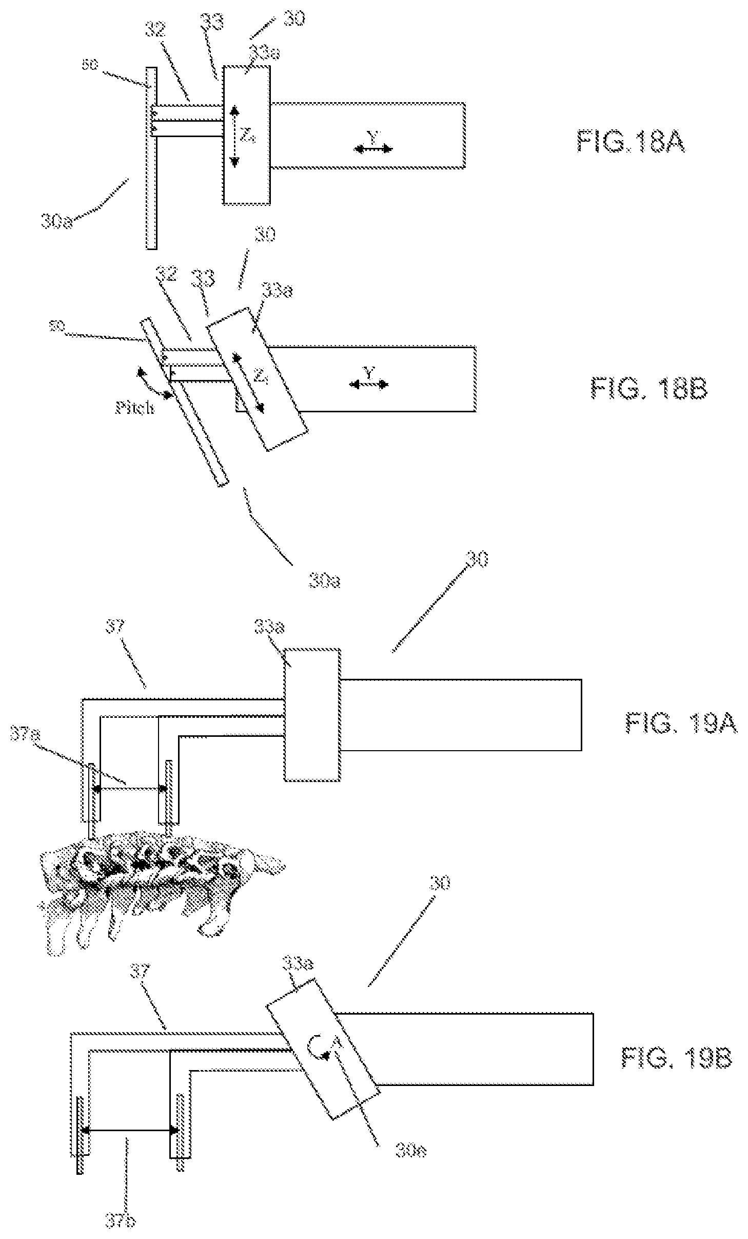
D00015

D00016
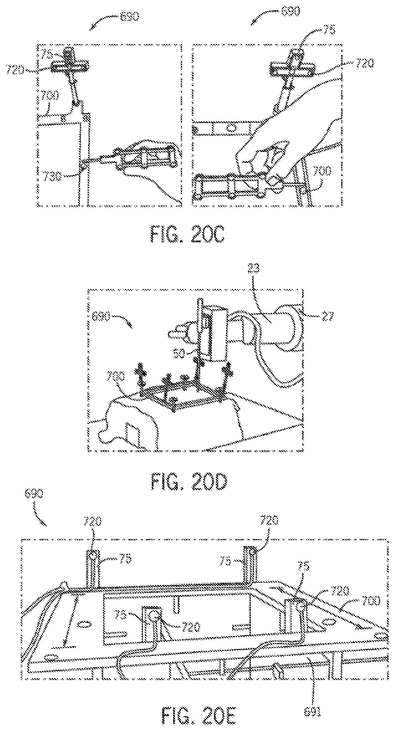
D00017

D00018
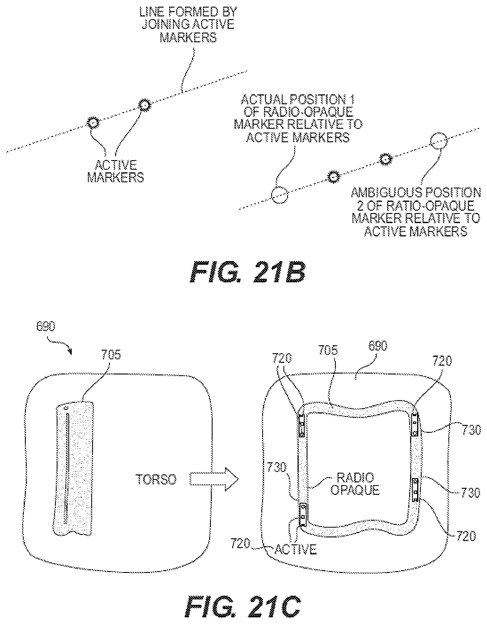
D00019

D00020

D00021
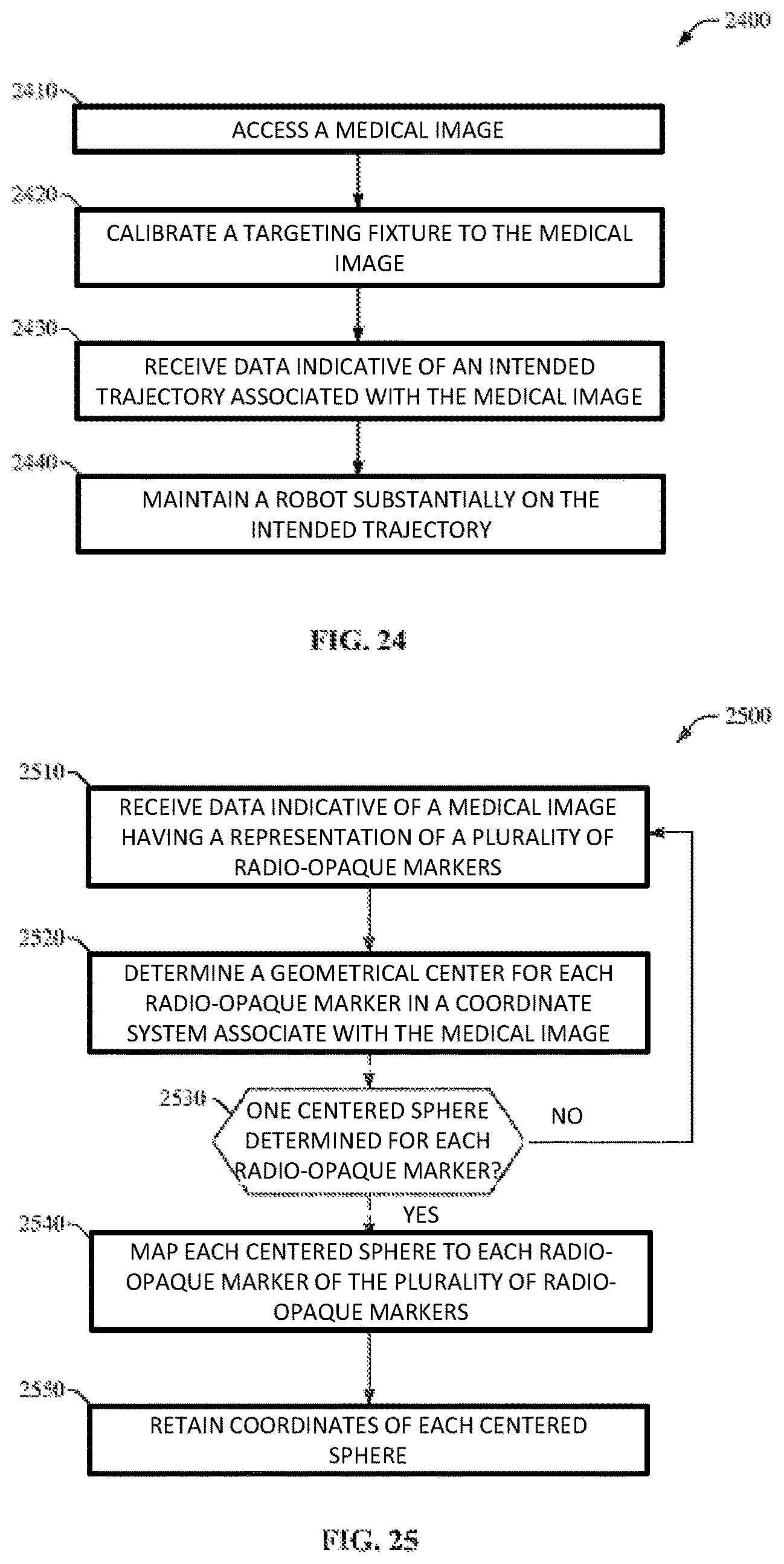
D00022

D00023

D00024

D00025

D00026

D00027
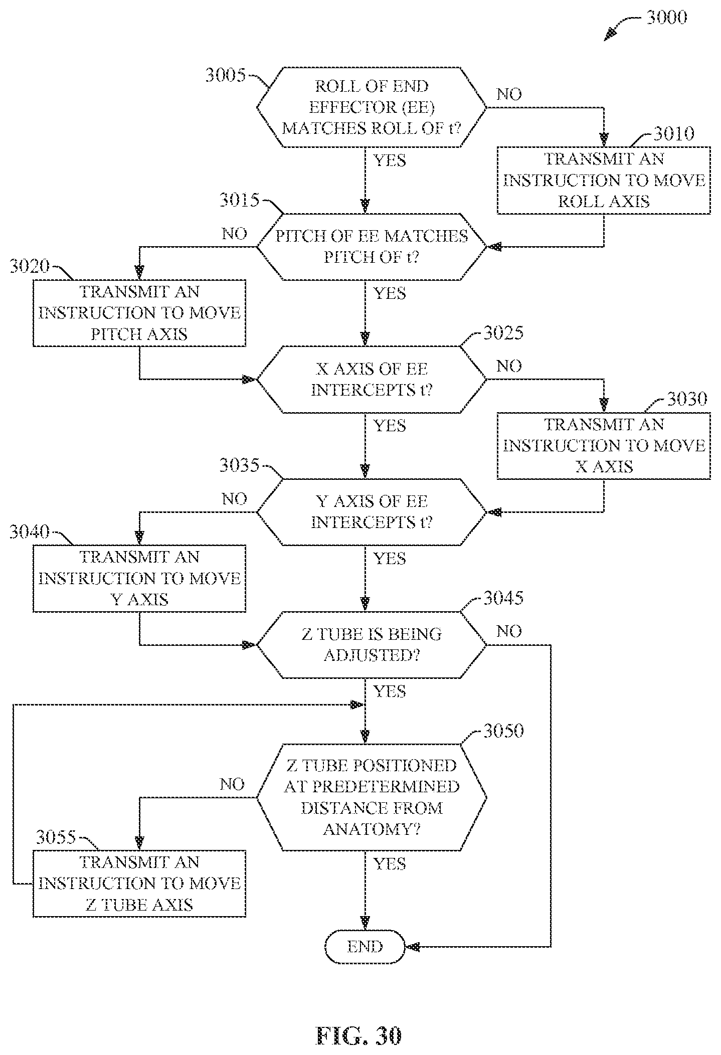
D00028

D00029

D00030

D00031
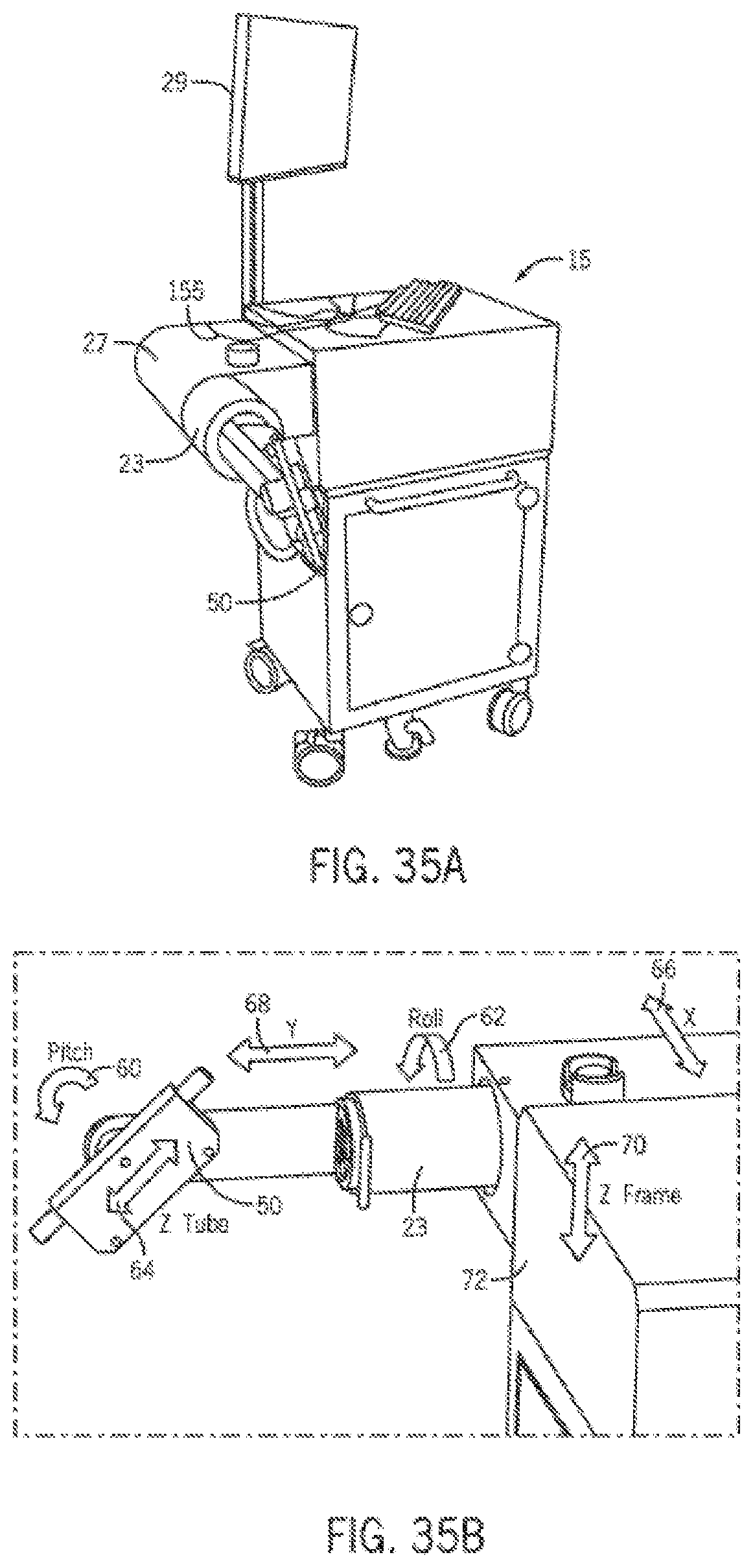
M00001

M00002

M00003

XML
uspto.report is an independent third-party trademark research tool that is not affiliated, endorsed, or sponsored by the United States Patent and Trademark Office (USPTO) or any other governmental organization. The information provided by uspto.report is based on publicly available data at the time of writing and is intended for informational purposes only.
While we strive to provide accurate and up-to-date information, we do not guarantee the accuracy, completeness, reliability, or suitability of the information displayed on this site. The use of this site is at your own risk. Any reliance you place on such information is therefore strictly at your own risk.
All official trademark data, including owner information, should be verified by visiting the official USPTO website at www.uspto.gov. This site is not intended to replace professional legal advice and should not be used as a substitute for consulting with a legal professional who is knowledgeable about trademark law.